US11243293B2 - Radar-based system for sensing touch and in-the-air interactions - Google Patents
Radar-based system for sensing touch and in-the-air interactions Download PDFInfo
- Publication number
- US11243293B2 US11243293B2 US15/889,149 US201815889149A US11243293B2 US 11243293 B2 US11243293 B2 US 11243293B2 US 201815889149 A US201815889149 A US 201815889149A US 11243293 B2 US11243293 B2 US 11243293B2
- Authority
- US
- United States
- Prior art keywords
- radio waves
- radar
- electronic device
- transmitters
- objects
- Prior art date
- Legal status (The legal status is an assumption and is not a legal conclusion. Google has not performed a legal analysis and makes no representation as to the accuracy of the status listed.)
- Active, expires
Links
Images


Classifications
-
- G—PHYSICS
- G06—COMPUTING; CALCULATING OR COUNTING
- G06F—ELECTRIC DIGITAL DATA PROCESSING
- G06F3/00—Input arrangements for transferring data to be processed into a form capable of being handled by the computer; Output arrangements for transferring data from processing unit to output unit, e.g. interface arrangements
- G06F3/01—Input arrangements or combined input and output arrangements for interaction between user and computer
- G06F3/017—Gesture based interaction, e.g. based on a set of recognized hand gestures
-
- G—PHYSICS
- G01—MEASURING; TESTING
- G01S—RADIO DIRECTION-FINDING; RADIO NAVIGATION; DETERMINING DISTANCE OR VELOCITY BY USE OF RADIO WAVES; LOCATING OR PRESENCE-DETECTING BY USE OF THE REFLECTION OR RERADIATION OF RADIO WAVES; ANALOGOUS ARRANGEMENTS USING OTHER WAVES
- G01S13/00—Systems using the reflection or reradiation of radio waves, e.g. radar systems; Analogous systems using reflection or reradiation of waves whose nature or wavelength is irrelevant or unspecified
- G01S13/02—Systems using reflection of radio waves, e.g. primary radar systems; Analogous systems
- G01S13/06—Systems determining position data of a target
- G01S13/42—Simultaneous measurement of distance and other co-ordinates
-
- G—PHYSICS
- G01—MEASURING; TESTING
- G01S—RADIO DIRECTION-FINDING; RADIO NAVIGATION; DETERMINING DISTANCE OR VELOCITY BY USE OF RADIO WAVES; LOCATING OR PRESENCE-DETECTING BY USE OF THE REFLECTION OR RERADIATION OF RADIO WAVES; ANALOGOUS ARRANGEMENTS USING OTHER WAVES
- G01S13/00—Systems using the reflection or reradiation of radio waves, e.g. radar systems; Analogous systems using reflection or reradiation of waves whose nature or wavelength is irrelevant or unspecified
- G01S13/87—Combinations of radar systems, e.g. primary radar and secondary radar
- G01S13/876—Combination of several spaced transponders or reflectors of known location for determining the position of a receiver
-
- G—PHYSICS
- G01—MEASURING; TESTING
- G01S—RADIO DIRECTION-FINDING; RADIO NAVIGATION; DETERMINING DISTANCE OR VELOCITY BY USE OF RADIO WAVES; LOCATING OR PRESENCE-DETECTING BY USE OF THE REFLECTION OR RERADIATION OF RADIO WAVES; ANALOGOUS ARRANGEMENTS USING OTHER WAVES
- G01S13/00—Systems using the reflection or reradiation of radio waves, e.g. radar systems; Analogous systems using reflection or reradiation of waves whose nature or wavelength is irrelevant or unspecified
- G01S13/88—Radar or analogous systems specially adapted for specific applications
- G01S13/89—Radar or analogous systems specially adapted for specific applications for mapping or imaging
-
- G—PHYSICS
- G01—MEASURING; TESTING
- G01S—RADIO DIRECTION-FINDING; RADIO NAVIGATION; DETERMINING DISTANCE OR VELOCITY BY USE OF RADIO WAVES; LOCATING OR PRESENCE-DETECTING BY USE OF THE REFLECTION OR RERADIATION OF RADIO WAVES; ANALOGOUS ARRANGEMENTS USING OTHER WAVES
- G01S7/00—Details of systems according to groups G01S13/00, G01S15/00, G01S17/00
- G01S7/02—Details of systems according to groups G01S13/00, G01S15/00, G01S17/00 of systems according to group G01S13/00
- G01S7/41—Details of systems according to groups G01S13/00, G01S15/00, G01S17/00 of systems according to group G01S13/00 using analysis of echo signal for target characterisation; Target signature; Target cross-section
- G01S7/415—Identification of targets based on measurements of movement associated with the target
-
- G—PHYSICS
- G06—COMPUTING; CALCULATING OR COUNTING
- G06F—ELECTRIC DIGITAL DATA PROCESSING
- G06F3/00—Input arrangements for transferring data to be processed into a form capable of being handled by the computer; Output arrangements for transferring data from processing unit to output unit, e.g. interface arrangements
- G06F3/01—Input arrangements or combined input and output arrangements for interaction between user and computer
- G06F3/03—Arrangements for converting the position or the displacement of a member into a coded form
- G06F3/041—Digitisers, e.g. for touch screens or touch pads, characterised by the transducing means
- G06F3/0416—Control or interface arrangements specially adapted for digitisers
- G06F3/04166—Details of scanning methods, e.g. sampling time, grouping of sub areas or time sharing with display driving
-
- G—PHYSICS
- G06—COMPUTING; CALCULATING OR COUNTING
- G06F—ELECTRIC DIGITAL DATA PROCESSING
- G06F3/00—Input arrangements for transferring data to be processed into a form capable of being handled by the computer; Output arrangements for transferring data from processing unit to output unit, e.g. interface arrangements
- G06F3/01—Input arrangements or combined input and output arrangements for interaction between user and computer
- G06F3/03—Arrangements for converting the position or the displacement of a member into a coded form
- G06F3/041—Digitisers, e.g. for touch screens or touch pads, characterised by the transducing means
- G06F3/046—Digitisers, e.g. for touch screens or touch pads, characterised by the transducing means by electromagnetic means
-
- G06K9/00355—
-
- G—PHYSICS
- G06—COMPUTING; CALCULATING OR COUNTING
- G06V—IMAGE OR VIDEO RECOGNITION OR UNDERSTANDING
- G06V40/00—Recognition of biometric, human-related or animal-related patterns in image or video data
- G06V40/20—Movements or behaviour, e.g. gesture recognition
- G06V40/28—Recognition of hand or arm movements, e.g. recognition of deaf sign language
-
- G—PHYSICS
- G01—MEASURING; TESTING
- G01S—RADIO DIRECTION-FINDING; RADIO NAVIGATION; DETERMINING DISTANCE OR VELOCITY BY USE OF RADIO WAVES; LOCATING OR PRESENCE-DETECTING BY USE OF THE REFLECTION OR RERADIATION OF RADIO WAVES; ANALOGOUS ARRANGEMENTS USING OTHER WAVES
- G01S13/00—Systems using the reflection or reradiation of radio waves, e.g. radar systems; Analogous systems using reflection or reradiation of waves whose nature or wavelength is irrelevant or unspecified
- G01S13/02—Systems using reflection of radio waves, e.g. primary radar systems; Analogous systems
- G01S13/06—Systems determining position data of a target
- G01S13/46—Indirect determination of position data
- G01S2013/466—Indirect determination of position data by Trilateration, i.e. two antennas or two sensors determine separately the distance to a target, whereby with the knowledge of the baseline length, i.e. the distance between the antennas or sensors, the position data of the target is determined
-
- G—PHYSICS
- G06—COMPUTING; CALCULATING OR COUNTING
- G06F—ELECTRIC DIGITAL DATA PROCESSING
- G06F2203/00—Indexing scheme relating to G06F3/00 - G06F3/048
- G06F2203/041—Indexing scheme relating to G06F3/041 - G06F3/045
- G06F2203/04104—Multi-touch detection in digitiser, i.e. details about the simultaneous detection of a plurality of touching locations, e.g. multiple fingers or pen and finger
-
- G—PHYSICS
- G06—COMPUTING; CALCULATING OR COUNTING
- G06F—ELECTRIC DIGITAL DATA PROCESSING
- G06F2203/00—Indexing scheme relating to G06F3/00 - G06F3/048
- G06F2203/041—Indexing scheme relating to G06F3/041 - G06F3/045
- G06F2203/04108—Touchless 2D- digitiser, i.e. digitiser detecting the X/Y position of the input means, finger or stylus, also when it does not touch, but is proximate to the digitiser's interaction surface without distance measurement in the Z direction
Definitions
- This disclosure generally relates to electronic detection of an object.
- a controller such as a mouse, or an operation panel may traditionally be used to interact with an electronic device.
- Touch interactions or in-the-air gesture interactions are increasingly used to interact with electronic devices.
- touch or in-the-air interactions may increase interaction space, freedom, convenience, intuitiveness, etc. for users operating smart devices and electronic systems.
- Touch or in-the-air gesture interactions are typically accomplished through resistive, capacitive, surface acoustic wave, camera or infrared technologies.
- resistive, capacitive, surface acoustic wave, camera or infrared technologies are typically accomplished through resistive, capacitive, surface acoustic wave, camera or infrared technologies.
- these technologies are not robust to changes in lighting conditions, may be susceptible to hacking or spoofing, and/or require considerable processing power and cost.
- FIG. 1 illustrates an example radar-based sensing system for detecting touch and in-the-air interactions.
- FIG. 2 illustrates an example radar-based sensing system deployed on a device equipped with a display.
- FIG. 3 illustrates example hardware of a radar-based sensing system.
- FIG. 4 illustrates an example processing flow implemented by an example radar-based sensing system for scene and gesture analysis.
- FIG. 5 illustrates a plurality of example gestures that can be detected by radar imaging.
- FIGS. 6A-B illustrates a plurality of example gestures that can be detected by trilateration.
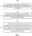
- FIG. 7 illustrates an example method for selecting between trilateration and radar imaging for a radar-based sensing system.
- FIG. 8 illustrates an example layout of inward-facing and outward-facing transceivers of a radar-based sensing system.
- FIG. 9 illustrates an example method for using a radar-based sensing system with inward-facing and outward-facing transceivers.
- FIG. 10 illustrates an example processing of radio waves by carrier coding.
- FIG. 11 illustrates an example processing of a radio wave by phase coding.
- FIG. 12 illustrates an example method for operating a radar-based sensing system in several transmission operating modes.
- FIG. 13 illustrates an example computer system.
- Radar an abbreviation for “radio detection and ranging,” is an object detection system that uses radio waves (electromagnetic waves between 3 MHz and 120 GHz) to determine range, velocity, angular direction, size and shape of objects.
- radio waves electromagnetic waves between 3 MHz and 120 GHz
- a transmitter emits radio waves, which are reflected, scattered or absorbed when they come into contact with an object.
- Radio waves reflected or scattered towards a receiver are then processed to determine range, velocity, angular direction, size, shape, or other features of the object.
- the radar-based sensing system described herein uses radio waves to detect user interactions with an electronic device.
- the radar-based sensing system may detect touch-gesture interactions when users are close to the radar-based sensing system.
- the radar-based sensing system may detect in-the-air gesture interactions when users are away from the radar-based sensing system.
- users may be 1 feet, 30 feet, or any distance between 1 feet and 30 feet, away from the radar-based sensing system.
- the radar-based sensing system may dispose transmitters that transmit radio waves at different angles (e.g., inward and outward) with respect to the system.
- the radar-based sensing system may select from a number of different operating modes to transmit radio waves to fulfill different requirements (e.g., low resolution, high resolution, high frame rate, etc.).
- a radar-based sensing system may use different data processing modules (e.g., trilateration and radar imaging) for different applications (e.g., simple gesture recognition, complex gesture recognition, scene analysis, etc.).
- a radar-based sensing system may dynamically switch between different transmission operating modes or different data processing modules.
- the radar-based sensing system disclosed herein can satisfy a broad range of requirements (such as imaging or object tracking requirements) by selecting a particular combination of transmitters, data processing modules, and transmission operating modes.
- the radar-based sensing system may provide near-field, simple gesture recognition in a noisy environment; yet when higher resolution is required, the system may also provide far-field, complex gesture recognition by selecting a different transmission operating mode and/or data processing module (or both).
- Particular embodiments of the radar-based sensing system described herein may operate even when there is limited visible light or when smoke, steam, fog, snow, rain, etc. are present.
- Particular embodiments of the radar-based sensing system described herein may detect in-the-air interactions through materials such as walls or glass.
- particular embodiments permit concealed installation of the radar-based sensing system.
- the system may be installed behind walls, covers, etc.
- the radar-based sensing system may be used in public displays, e.g., through-window store interactive displays.
- the radar-based sensing system described herein may replace or complement capacitive touch.
- capacitive touch sensors may be expensive in large display, and thus radar-based sensing systems become more economical.
- the radar-based sensing system described herein may also improve user privacy and be capable of nighttime operation because no cameras are required.
- the radar-based sensing system described herein may allow both touch and in-the-air interactions and may allow users to be far away from the system during in-the-air interactions.
- the radar-based sensing system may be used in TVs, projectors, car control systems that use gestures for operation, home appliances such as sounds systems and kitchen appliances, and interactive gaming, etc.
- a radar-based sensing system may be used in in-home presence sensing and/or tracking (e.g., from a TV or sound bar), which may be used to achieve more effective advertisement delivery.
- Particular embodiments of the radar-based sensing system described herein may require relatively little processing power and low cost to manufacture.
- the radar-based sensing system may be used in compact consumer products such as smart phones, tablets, wearable devices, VR/AR headsets, etc.
- Particular embodiments of the radar-based sensing system described herein may be used in a variety of other scenarios.
- this disclosure describes and illustrates particular use cases of the radar-based sensing system, this disclosure contemplates any suitable use cases of the radar-based sensing system described herein.
- FIG. 1 illustrates an example radar-based sensing system for detecting touch and in-the-air interactions.
- the radar-based sensing system may detect that user 101 interacts with the system by touching the system. User 101 may perform different touch gestures as a way of instructing the system to implement different functions.
- the radar-based sensing system may identify these touch gestures and implement the different functions.
- the radar-based sensing system may detect that user 102 interacts with the system via in-the-air gestures. User 102 may perform different in-the-air gestures as a way of instructing the system to implement functions.
- the radar-based sensing system may identify these in-the-air gestures and implement the appropriate functions.
- the radar-based sensing system may detect that user 103 stands in front of the system.
- the radar-based sensing system may determine the height, size, location, posture, or other attributes of user 103 .
- the radar-based sensing system may detect that user 104 is sitting in front of the system.
- the radar-based sensing system may determine the sitting position and location of user 104 , among other features.
- FIG. 2 illustrates an example prototype of a radar-based sensing system 200 deployed on a device equipped with a display 215 .
- the radar-based sensing system 200 may include a plurality of radar transceivers 205 and a plurality of radar transceivers 210 .
- the radar-based sensing system 200 in FIG. 2 may include four transceivers 205 (i.e., 205 A- 205 D) and four transceivers 210 (i.e., 210 A- 210 D).
- each of the plurality of radar transceivers 205 or radar transceivers 210 may include one or more radar transmitters and one or more radar receivers.
- the one or more radar transmitters may transmit radio waves into an area in the vicinity of the radar-based sensing system 200 .
- the vicinity of the radar-based sensing system 200 may include the area near or surrounding the radar-based sensing system 200 .
- the vicinity may be the area within a 2-foot radius of the radar-based sensing system 200 .
- the vicinity may be the area within a 30-foot radius of the radar-based sensing system 200 .
- the vicinity may be the area within a 15-foot radius of the radar-based sensing system 200 .
- the vicinity may be a region within which the transceivers are capable of radiating radio waves above a certain power or energy threshold.
- the power or energy threshold may depend on the noise present in received radio waves.
- a vicinity may take any suitable shape, such as a circular or rectangular shape.
- the vicinity of a radar-based sensing system may depend on the particular application or implementation of the system. For example, if a radar-based sensing system is used to detect interaction with a small store display, such as interaction with a particular smart phone in a row of smart phones, then the vicinity may be 2 feet or less. As another example, if a radar-based sensing system is used in a large display, such as a TV in a user's living room, then the vicinity of the radar-based sensing system may be around 15 feet from the radar-based sensing system.
- the one or more radar receivers may receive radio waves reflected off one or more objects in the vicinity of the radar-based sensing system 200 . In other embodiments, the one or more radar receivers may receive radio waves scattered by one or more objects in the vicinity of the radar-based sensing system 200 .
- the plurality of radar transceivers 205 and the plurality of radar transceivers 210 may be disposed on a substantially rectangular edge of the radar-based sensing system 200 surrounding the display 215 .
- transceivers 205 A- 205 D in FIG. 2 may be disposed in the corners of the substantially rectangular edge surrounding the display 215 and transceivers 210 A- 210 D in FIG.
- transceivers 2 may be disposed in between the corners of the substantially rectangular edge surrounding the display 215 .
- this disclosure describes disposing transceivers at the edges of a display, transceivers may be disposed in any suitable way that radio waves can reach users and radar-based sensing systems can detect user gesture interactions.
- the radar-based sensing system 200 may also include one or more non-transitory storage media embodying instructions.
- the radar-based sensing system 200 may additionally include one or more processors.
- the one or more processors may be operable to execute the instructions to detect user gesture interactions. While this disclosure describes various aspects of transmitters and receivers within a transceiver, this disclosure contemplates that those components may by implemented in a radar-based sensing system separately from a transceiver, that a transceiver may include only some of those components, and/or that a transceiver may include additional components of the radar-based sensing system.
- FIG. 3 illustrates example hardware of a radar-based sensing system, such as the radar-based sensing system 200 .
- the radar-based sensing system may include an antenna array 305 , a radio transmitter 310 , a radio receiver 315 , a control unit 320 , and a processing unit 325 .
- the antenna array 305 may include a transmitter array 301 integrating one or more antennas 302 .
- the antenna array 305 may also include a receiver array 303 integrating one or more antennas 304 .
- the radar-based sensing system may implement a transmission mode and a reception mode.
- radio transmitter 310 may supply an electric current oscillating at radio frequency (3 MHz to 120 GHz) to transmitter array 301 .
- the antennas 302 of transmitter array 301 may then radiate energy from the electric current as radio waves.
- the radio waves may reach objects, such as users, and be reflected back to the radar-based sensing system.
- the radar-based sensing system may then operate in receiving mode.
- the antennas 304 of the receiver array 303 may detect the reflected radio waves.
- the antennas 304 may further produce a voltage and provide the voltage to the radio receiver 315 .
- the radio receiver 315 may then amplify the voltage and send the amplified voltage to the processing unit 325 .
- the processing unit 325 may then detect the gesture interactions based on the amplified voltage.
- the control unit 320 may control the radio transmitter 310 for electric current generation and the radio receiver 315 for voltage amplification.
- the control unit 320 and processing unit 325 may communicate with each other to detect gesture interactions.
- this disclosure illustrates a particular hardware of a radar-based sensing system, this disclosure contemplates any suitable hardware of the radar-based sensing system.
- a radar-based sensing system may transmit different types of radio waves in different ways.
- a radar-based sensing system may transmit radio waves as high-frequency impulse signals having relatively high power. After transmitting one high-frequency impulse signal of high power, the radar-based sensing system may cease transmission to receive the reflected signal. Once the reflected signal is received, the radar-based sensing system may transmit another high-frequency impulse signal.
- the radar-based sensing system may determine a direction, distance, height, and/or altitude of an object based on a measured antenna position and a propagation time of the impulse signals.
- a radar-based sensing system may continuously transmit radio waves using high-frequency signals. As an example, the signals may be constant in amplitude and frequency.
- a radar-based sensing system may use such signals for measuring a speed of the target user.
- the signals may be constant in amplitude but modulated in frequency.
- the radar-based sensing system 200 may use such signals for measuring a distance of an object from the system.
- FIG. 4 illustrates an example processing flow 400 implemented by an example radar-based sensing system for scene and gesture analysis.
- the processing flow may use data from the transmitter array 301 and the receiver array 303 .
- the transmitter array 301 and the receiver array 303 may be operated in monostatic configuration.
- the transmitter array 301 and the receiver array 303 may be operated in bistatic (MIMO) configuration.
- a radar-based sensing system may use Signal Conditioning 410 to process Frame Data 405 from the transmitter array 301 and the receiver array 303 .
- Signal Conditioning 410 may remove noise from received radar signals.
- the radar-based sensing system may use Detection Module Selection 415 to determine whether to select Trilateration Module 420 or to select Radar Imaging Module 425 to process the data.
- the determination may be based on Scene Analysis 411 and Application Analysis 412 , described more fully below.
- Trilateration Module 420 may estimate one or more positions of one or more objects (e.g., users) that are in the vicinity of the radar-based sensing system. The estimated positions may be then input to Scene/Gesture Analysis Module 430 to detect different scenes or gestures.
- Radar Imaging Module 425 may estimate a plurality of features of the one or more objects (e.g., users) in the vicinity of the radar-based sensing system. The plurality of features may include size, position, orientation, and height. The estimated features may be then input to Scene/Gesture Analysis Module 430 to detect different scenes or gestures.
- Radar Imaging Module 425 may use the estimated positions of the one or more objects (e.g., users) by Trilateration Module 420 to reduce the probability of detecting false objects (e.g., users). In other embodiments, Trilateration Module 420 may use the detection results of Radar Imaging Module 425 to improve the estimation of the positions of the objects (e.g., users).
- Detection Module Selection 415 may select between Trilateration Module 420 and Radar Imaging Module 425 based on one or more interactions requirements specified by an application or process using the interaction data.
- applications may be specified by a standalone application or by a process internal to, e.g., an operating system executing on the device the user is interacting with.
- Application Analysis Module 412 may identify one or more application requirements for processing user interactions with a radar-based sensing system.
- Detection Module Selection 415 may select Radar Imaging Module 425 when the one or more requirements include tracking the one or more objects, determining a distance between the one or more objects and the radar-based sensing system, determining a shape of the one or more objects, and/or determining a size of the one or more objects.
- Detection Module Selection 415 may select Trilateration Module 420 when the one or more requirements include processing received radio waves at a frame rate that exceeds a threshold frame rate.
- user interactions such as hand movements
- the radar-based sensing system may therefore select Trilateration Module 420 to process user interactions.
- Detection Module Selection 415 may select Radar Imaging Module 425 when one or more interaction requirements include determining an orientation of the one or more objects.
- the one or more objects may include a hand or limb of a user.
- the one or more objects may include a plurality of fingers of a user.
- An application such as a drawing or game application, may require detecting the orientation of individual fingers, and thus Radar Imaging Module 420 may be used to process user interactions.
- Detection Module Selection 415 may select Radar Imaging Module 425 when the one or more requirements include identifying at least some of the one or more objects.
- the Detection Module Selection 415 may determine a set of the identified objects on which to focus further processing based on Scene Analysis Module 411 , which may identify detection requirements based on application requirements and, perhaps, environmental conditions. For example, an application may require that only users' hands be tracked, and Scene Analysis Module 411 may determine whether detecting user's hands in the area of the radar-based system requires using Trilateration Module 420 or Radar Imaging Module 425 .
- Detection Module Selection 415 may determine the selection between Trilateration Module 420 and Radar Imaging Module 425 based on a variety of conditions. In particular embodiments, Detection Module Selection 415 may select Trilateration Module 420 when a speed of at least one of the one or more objects being tracked exceeds a predetermined threshold. In particular embodiments, Detection Module Selection 415 may select Trilateration Module 420 when the position of an object being tracked corresponds to a position of a cursor displayed on the display 215 of the radar-based sensing system 200 . In particular embodiments, it may be beneficial to use Trilateration Module 420 to process frame data 405 . Benefits to using Trilateration Module 420 instead of Radar Imaging Module 425 may include faster data processing to detect gesture interactions efficiently, less sensitivity to timing errors, higher frame-rate processing of data, and precise localization of objects in the vicinity of the radar-based sensing system.
- Detection Module Selection 415 may select Radar Imaging Module 425 if a scene needs to be analyzed in detail.
- Radar Imaging Module 425 may form a 3D image representing the scene.
- the 3D image may be then input to the module of Scene/Gesture Analysis 430 for scene analysis.
- the module of Scene/Gesture Analysis 430 may analyze the size, position, posture, etc. of one or more users—or of a portion (such as arm and hand) of one or more users—and decide what part of the scene to analyze or track.
- Detection Module Selection 415 may select Radar Imaging Module 425 when noise associated with the received radio waves exceeds a predetermined threshold.
- Trilateration Module 420 may fail to adequately identify a target object when noise is present, even if only a simple position of the target object is needed.
- a radar-based sensing system may select Radar Imaging Module 425 to analyze the scene. Once a target region containing the object is identified, the radar-based sensing system may focus on the corresponding portion of the signal to avoid noisy regions and improve the accuracy of Trilateration Module 420 .
- a radar-based sensing system may dynamically select partial imaging regions for Radar Imaging Module 425 to analyze in order to increase the efficiency.
- Frame Data 405 may include one or more temporally sequential frames.
- Detection Module Selection 415 may dynamically determine, for each frame or for a number of frames, whether to process the frame(s) by using Trilateration Module 420 or Radar Imaging Module 425 .
- the dynamic determination may be made based on application and scene requirements, such as those described above.
- an application's interaction detection requirements may change at different points in the flow of user experience (UX). For example, in the main menu of the application, a simple cursor may be sufficient to interact with the application. Thus, because the application only requires the user to control a position of a cursor, Detection Module Selection 415 may select Trilateration Module 420 .
- the application may require operation based on complex gestures.
- the complex gestures may include selecting sub-menu items with fingers, rotating a graphical object with hand orientation, or controlling graphical objects or characters in a game.
- Detection Module Selection 415 may select Radar Imaging Module 425 to process those more complex interactions.
- a user may have the option to select another menu (a menu different from the main menu). Therefore, the application once again may only require a user to specify a position of a cursor.
- Detection Module Selection 415 may accordingly select Trilateration Module 420 for the frame data corresponding to interaction with the main menu.
- Detection Module Selection 415 may select Radar Imaging Module 425 again when the application requires complex gesture detection.
- an application may require scene analysis followed by simple tracking.
- an IOT (internet of things) application of a TV may initially analyze a scene using Radar Imaging Module 425 to understand the position, size, or posture of users or a particular room layout. Once scene analysis is completed, the application may decide to track certain users or portions of users, such as hands. Depending on the circumstances, Radar Imaging Module 425 may be selected again to determine which user should be the target. After the target is determined, the application may only require simple positions of the target so Trilateration Module 420 may be selected.
- Detection Module Selection 415 may select the appropriate processing module on a frame-by-frame basis, on a conditional basis (e.g., as application requirements change), as part of an initialization process, or any suitable combination thereof.
- Radar Imaging Module 425 may coherently or incoherently combine data from the plurality of radar transceivers 205 and the plurality of radar transceivers 210 to form a 2D or 3D image over a user defined image space.
- each radar transceiver 205 or radar transceiver 210 may be programmed and reconfigured as either a transmitter or receiver and each of them may return one-dimensional data.
- Radar Imaging Module 425 may use one or more imaging algorithms to form images from frame data 405 .
- the one or more imaging algorithms may include a back-projection algorithm and a MIMO range migration algorithm.
- Radar Imaging Module 425 may use a back-projection algorithm.
- frame data 405 may be first filtered using a low pass filter. Then the back-projection algorithm may choose to compute the envelope of the filtered data or not corresponding to incoherent processing or coherent processing, respectively.
- the envelope of the filtered data may be computed, retaining only the signal amplitude. Incoherent processing may be less susceptible to calibration errors but it may give a lower resolution image.
- coherent processing the envelope may be not computed and the signal may be left at the carrier frequency. As a result, the phase information of the signal may be retained.
- Radar Imaging Module 425 may then form a 2D or 3D image based on a pre-defined imaging space.
- the pre-defined imaging space may be a plane with discrete coordinates or a volume with discrete coordinates.
- the resolution and size of the imaging space may be determined as one or more functions of the array spacing of the antenna array 305 , the number of transceivers 205 and transceivers 210 , and the bandwidth of the radio waves.
- the positions of the one or more objects may be estimated using blob detection. The estimated positions may be used for scene/gesture analysis 430 .
- Trilateration Module 420 and Radar Imaging Module 425 may implement any suitable trilateration or imaging processing algorithms, respectively, to process frames of data.
- This disclosure contemplates that the algorithms may be executed by any suitable computing device, which, in many instances, will be the computing device with which the user is interacting. However, this disclosure also contemplates that such processing may be performed by a remote device, such as server device, or by a combination of devices.
- FIG. 5 illustrates a plurality of example interactions that are detectable based on radar imaging 425 .
- Radar Imaging Module 425 may detect the orientation of a hand.
- Radar Imaging Module 425 may detect a hand pose.
- Radar Imaging Module 425 may detect a pose by one arm or a pose by two arms.
- Radar Imaging Module 425 may detect a finger pose.
- this disclosure illustrates particular gestures detectable based on radar imaging, this disclosure contemplates any suitable gestures detectable based on radar imaging in any suitable manner.
- Trilateration Module 420 may estimate one or more positions of the one or more objects in the vicinity of the radar-based sensing system. For example, frame data 405 may be first filtered using a low pass filter. The envelope of the filtered data may be then computed. Trilateration Module 420 may further estimate the positions of the objects based on the computed envelope. In particular embodiments, the radar-based sensing system may further detect interactions based on the estimated positions of the objects. FIG. 6 illustrates a plurality of example interactions that are detectable based on Trilateration Module 420 . As an example and not by way of limitation, the interactions may include gestures such as a swipe by a hand, a touch by a hand, or a click by a hand.
- the gestures may be performed by different users. For example, in FIG. 6A user 601 may perform a swipe by one hand and user 602 may perform a touch by one hand. As another example and not by way of limitation, the gestures may be performed by two hands. For example, in FIG. 6B user 603 may pinch, zoom, or rotate using two hands.
- Trilateration Module 420 process an object as single entity, while Radar Imaging Module 425 may detect various portions of objects and process them separately.
- Trilateration Module 420 may detect hand of User 601 as a single object.
- Trilateration Module 420 may track the position of the hand regardless of what the particular fingers of the hand are doing.
- Radar Imaging Module 425 may detect the position of the hand and the position(s) of individual fingers of the hand, and differentiate between the position(s).
- a number of advantages result from dynamically switching between Trilateration Module 420 and Radar Imaging Module 425 .
- One advantage may include the ability to process frames with higher frame rates and reduced processing complexity compared to imaging-only solutions.
- Another advantage may include smarter imaging driven by the use of Trilateration Module 420 to pinpoint sub-regions of interest, for example by quickly detecting the portions of a scene that are moving, before devoting the processing resources required to image a scene.
- Another advantage may include potentially using fewer antennas, for example because Trilateration Module 420 can, in some embodiments, requiring using only three antennas to track an object.
- FIG. 7 illustrates an example method 700 for selecting between Trilateration Module 420 and Radar Imaging Module 425 for a radar-based sensing system.
- the method may begin at step 710 .
- the radar-based sensing system may transmit, from one or more of the transmitters, radio waves into an area in the vicinity of the radar-based sensing system.
- the transmitters may be integrated in the transceivers 205 or transceivers 210 .
- the radar-based sensing system may receive, at one or more of the receivers, radio waves reflected off one or more objects in the vicinity of the radar-based sensing system.
- the receivers may be integrated in the transceivers 205 or transceivers 210 and the one or more objects may be one or more users.
- the radar-based sensing system may select, based on one or more requirements for processing user interactions with the radar-based sensing system 200 : a Trilateration Module 420 processing module for processing subsequently received radio waves; or an imaging 425 processing module for processing the subsequently received radio waves. For example, any of the requirements described above, or any suitable combination thereof, may be used to select the appropriate processing module.
- Particular embodiments may repeat one or more steps of the method of FIG. 7 , where appropriate.
- this disclosure describes and illustrates particular steps of the method of FIG. 7 as occurring in a particular order, this disclosure contemplates any suitable steps of the method of FIG. 7 occurring in any suitable order.
- this disclosure describes and illustrates an example method for sensing an object based on electromagnetic radiation, including the particular steps of the method of FIG. 7 , this disclosure contemplates any suitable method for sensing an object based on electromagnetic radiation, which may include all, some, or none of the steps of the method of FIG. 7 , where appropriate.
- this disclosure describes and illustrates particular components, devices, or systems carrying out particular steps of the method of FIG. 7 , this disclosure contemplates any suitable combination of any suitable components, devices, or systems carrying out any suitable steps of the method of FIG. 7 .
- Radar antennas are directional, and thus transmission and detection of radar waves from any one antenna (or transmitter-receiver antenna pair) occurs in a relatively limited field of view.
- particular embodiments of the radar-based sensing system described herein may simultaneously detect interactions from a plurality of users (or other objects) situated through an environment.
- FIG. 8 illustrates an example layout of inward-facing and outward-facing transceivers of a radar-based sensing system.
- the radar-based sensing system may configure the plurality of transceivers 205 to be inward and the plurality of transceivers 210 to be outward.
- the transmitters integrated in inward transceivers 205 may cover relatively near (e.g., within 2 feet of display 215 ) interactions and the transmitters integrated in outward transceivers 210 may cover relatively far interactions.
- the plurality of transceivers 205 and transceivers 210 may be disposed on a substantially rectangular edge of the radar-based sensing system 200 surrounding the display 215 .
- Transceivers 205 A- 205 D may be disposed in the corners of the substantially rectangular edge and transceivers 210 A- 210 D may be disposed in between the corners of the substantially rectangular edge.
- each of the transmitters integrated in inward transceivers 205 may transmit the majority of its radio waves in a direction parallel to the display 215 .
- each of the transmitters integrated in inward transceivers 210 may transmit the majority of its radio waves in a direction perpendicular to the display 215 .
- one or more receivers integrated in the transceivers 205 and the transceivers 210 may detect reflections and/or scatterings of the transmitted radio waves off one or more objects in the vicinity of the radar-based sensing system.
- the reflections and/or scatterings may correspond to user interactions with the radar-based sensing system.
- this disclosure illustrates a particular layout of transceivers having a particular orientation
- this disclosure contemplates any suitable layout of transceivers with any suitable orientation.
- this disclosure contemplates adding additional transceivers to the edge of display 215 that are oriented at an angle between parallel and perpendicular to the display.
- the radar-based sensing system of FIG. 8 may, as a result of inward-facing and outward-facing transceiver, simultaneous track objects relatively near to and relatively far from display 215 .
- the radar-based sensing system of FIG. 8 may track a user moving from near field (e.g., less than 2 feet away from display 215 ) to far field (e.g., more than 10 feet away).
- FIG. 9 illustrates an example method 900 for determining whether to transmit radio waves from inward transceivers 205 or to transmit radio waves from outward transceivers 210 .
- the method may begin at step 910 .
- the radar-based sensing system may transmit, from each of the transmitters of inward transceivers 205 , the majority of its radio waves in a direction parallel to the display 215 ; and from each of the transmitters of outward transceivers 210 , the majority of its radio waves in a direction perpendicular to the display 215 .
- the radar-based sensing system may detect, at one or more receivers, reflections and/or scatterings of the transmitted radio waves off one or more objects in the vicinity of the radar-based sensing system, wherein the reflections and/or scatterings correspond to a user interaction with the radar-based sensing system.
- the radar-based sensing system may detect, based on the received radio waves from the receivers, an object in the vicinity of the radar-based sensing system.
- the object may include a hand of a user.
- the radar-based sensing system 200 may determine, based on the received radio waves, a distance between the object and the radar-based sensing system.
- the radar-based sensing system may transmit radio waves from the transmitters in inward transceivers 205 when the distance is less than a predetermined threshold; and transmit radio waves from the transmitters in outward transceivers 210 when the distance is greater than the predetermined threshold.
- the predetermined threshold may be approximately two feet.
- the radar-based sensing system 200 may detect gestures illustrated in FIG. 5 and/or FIG. 6 based on radio waves from transceivers 205 A- 205 D when users 601 - 603 are close to the display 215 (e.g., within a distance of 2 feet).
- the radar-based sensing system 200 may detect the same gestures based on radio waves from transceivers 210 A- 210 D.
- the radar-based sensing system may operate both inward-facing and outward-facing transceivers if, e.g., objects are being detected in both near field and far field.
- frames from inward-facing transceivers may be processed according to a processing module, and frames from outward-facing transceivers may be processed according to another or the same processing module.
- Detection Module Selection 415 may decide which processing module to use for a subset of transceivers in a given orientation (or, in particular embodiments, even on a transceiver-by-transceiver basis).
- Particular embodiments may repeat one or more steps of the method of FIG. 9 , where appropriate.
- this disclosure describes and illustrates particular steps of the method of FIG. 9 as occurring in a particular order, this disclosure contemplates any suitable steps of the method of FIG. 9 occurring in any suitable order.
- this disclosure describes and illustrates an example method for sensing an object based on electromagnetic radiation, including the particular steps of the method of FIG. 9 , this disclosure contemplates any suitable method for sensing an object based on electromagnetic radiation, which may include all, some, or none of the steps of the method of FIG. 9 , where appropriate.
- this disclosure describes and illustrates particular components, devices, or systems carrying out particular steps of the method of FIG. 9 , this disclosure contemplates any suitable combination of any suitable components, devices, or systems carrying out any suitable steps of the method of FIG. 9 .
- a radar-based sensing system may select a transmission operating mode for one or more of its transmitters based on one or more preferences for detecting one or more objects in the vicinity of the radar-based sensing system.
- the transmission operating mode may include simultaneously transmitting from each of the plurality of transmitters, or transmitting from each transmitter in sequence, or transmitting from one of the plurality of transmitters.
- all transmitters in the plurality of transmitters are activated at substantially the same time.
- the one or more receivers are activated after transmitting from one of the transmitters and before transmitting from another one of the transmitters.
- the transmitter of transceiver 210 A may transmit, all the receivers of transceivers 210 A-D may receive, then the transmitter from transceiver 210 B may transmit, and so on.
- the one or more receivers are activated after transmitting from the one transmitter.
- the one or more preferences used to select a transmission operating mode may specify imaging the objects at a relatively higher resolution (e.g., at a resolution above a specified resolution threshold) for radar imaging 425 .
- a relatively higher resolution e.g., at a resolution above a specified resolution threshold
- the transmission operating mode may include transmitting from each transmitter in sequence with the one or more receivers being activated after transmitting from one of the transmitters and before transmitting from another one of the transmitters.
- the transmission operating mode may include simultaneously transmitting from each of the plurality of transmitters. When simultaneously transmitting from each of the plurality of transmitters, the transmission operating mode may additionally configure each transmitter to transmit radio waves using a different phase code.
- each transmitter transmitting radio waves using a different code may be achieved by phase coding.
- the one or more preferences may specify positioning the objects with relatively lower noise (e.g., with noise lower than a specified noise threshold).
- positioning the objects may be based on Trilateration Module 420 .
- the transmission operating mode may include transmitting from each transmitter in sequence with the one or more receivers being activated after transmitting from one of the transmitters and before transmitting from another one of the transmitters.
- the transmission operating mode may include simultaneously transmitting from each of the plurality of transmitters.
- the transmission operating mode may configure each transmitter to transmit radio waves in a different frequency band.
- each transmitter transmitting radio waves in a different frequency band may be achieved by carrier coding.
- the one or more preferences may specify imaging the objects at a relatively higher frame rate (e.g., at a frame rate above a specified frame rate threshold).
- the transmission operating mode may therefore include transmitting from one of the plurality of transmitters with the one or more receivers being activated after transmitting from the transmitter or simultaneously transmitting from each of the plurality of transmitters.
- the transmission operating mode may additionally configure each transmitter to transmit radio waves in a different frequency band or using a different phase code.
- the radar-based sensing system may switch between different transmission operating modes dynamically, e.g., for each frame of frame data 405 .
- the radar-based sensing system 200 may further transmit, from at least some of the plurality of transmitters in accordance with the transmission operating mode, radio waves into an area in the vicinity of the radar-based sensing system 200 .
- the radar-based sensing system 200 may then activate the one or more receivers to detect radio waves reflected off one or more objects in the vicinity of the radar-based sensing system 200 .
- FIG. 10 illustrates an example processing of radio waves by carrier coding.
- Carrier coding may allow for simultaneously transmitting from each of the plurality of transmitters, because each transmitter transmits in a unique frequency band.
- the example of FIG. 10 includes two radio waves, i.e., radio wave 1001 and radio wave 1002 .
- the two radio waves are transmitted simultaneously from 0 ns to approximately 6 ns.
- radio wave 1001 is centered at 3 GHz
- radio wave 1002 is centered at 7 GHz.
- the bandwidth is split, which may result in a loss of resolution.
- carrier coding may be used in applications including coarse scene analysis, presence detection and simple gesture recognition that require low-resolution imaging.
- FIG. 11 illustrates an example processing of a radio wave by phase coding.
- Phase coding may allow for simultaneously transmitting from each of the plurality of transmitters because each transmitter transmits a signal with a unique phase code.
- radio wave 1101 is phase coded from approximately 4 ns to 13 ns and retains its pure tone from approximately 14 ns to 26 ns.
- the phase coded output of radio wave 1101 has signal-noise-ratio (SNR) loss.
- SNR signal-noise-ratio
- orthogonal phase code may be used to prevent SNR loss.
- a radar-based sensing system may detect user interactions based on a plurality of different schemes.
- the radar-based sensing system may transmit radio waves from one of the transmitters in transceivers 205 .
- the radar-based sensing system 200 may then select Trilateration Module 420 for processing the reflected radio waves at the receivers.
- Trilateration Module 420 for processing the reflected radio waves at the receivers.
- simple gesture recognition in the near field that requires high frame rate may be achieved.
- the radar-based sensing system 200 may select Radar Imaging Module 425 for processing the reflected radio waves at the receivers.
- pose detection in the near field may be achieved accordingly.
- the radar-based sensing system may transmit radio waves from one of the transmitters in transceivers 210 .
- the radar-based sensing system 200 may then select Trilateration Module 420 for processing the reflected radio waves at the receivers.
- Trilateration Module 420 for processing the reflected radio waves at the receivers.
- simple gesture recognition in the far field that requires high frame rate may be achieved accordingly.
- the radar-based sensing system may select Radar Imaging Module 425 for processing the reflected radio waves at the receivers.
- pose detection in the far field may be achieved accordingly.
- a radar-based sensing system may transmit radio waves from each of the transmitters in transceivers 205 in sequence.
- the radar-based sensing system may then select Trilateration Module 420 for processing the reflected radio waves at the receivers.
- Trilateration Module 420 for processing the reflected radio waves at the receivers.
- simple gesture recognition in the near field that only requires low frame rate may be achieved.
- the radar-based sensing system may select Radar Imaging Module 425 for processing the reflected radio waves at the receivers.
- complex gesture recognition in the near field that only requires low frame rate may be achieved.
- the radar-based sensing system may transmit radio waves from each of the transmitters in transceivers 210 in sequence.
- the radar-based sensing system may then select Trilateration Module 420 for processing the reflected radio waves at the receivers.
- simple gesture recognition in the far field that only requires low frame rate may be achieved.
- the radar-based sensing system may select Radar Imaging Module 425 for processing the reflected radio waves at the receivers.
- complex gesture recognition in the far field that only requires low frame rate may be achieved.
- the radar-based sensing system may transmit radio waves from each of the transmitters in both transceivers 205 and transceivers 210 in sequence. The radar-based sensing system may then select Trilateration Module 420 for processing the reflected radio waves at the receivers.
- simple gesture recognition of multiple users in both near field and far field that only requires low frame rate may be achieved.
- the radar-based sensing system may select Radar Imaging Module 425 for processing the reflected radio waves at the receivers.
- complex gesture recognition of multiple users in both near field and far field that only requires low frame rate may be achieved.
- a radar-based sensing system may simultaneously transmit radio waves from each of the transmitters in transceivers 205 . Each transmitter may transmit radio waves in a different frequency band. The radar-based sensing system may then select Trilateration Module 420 for processing the reflected radio waves at the receivers. As an example and not by way of limitation, simple gesture recognition in the near field that requires high frame rate may be achieved. Alternatively, the radar-based sensing system may select Radar Imaging Module 425 for processing the reflected radio waves at the receivers. As an example and not by way of limitation, coarse scene analysis in the near field that requires high frame rate may be achieved. In particular embodiments, the radar-based sensing system may simultaneously transmit radio waves from each of the transmitters in transceivers 210 .
- Each transmitter may transmit radio waves in a different frequency band.
- the radar-based sensing system may then select Trilateration Module 420 for processing the reflected radio waves at the receivers.
- Trilateration Module 420 for processing the reflected radio waves at the receivers.
- simple gesture recognition in the far field that requires high frame rate may be achieved.
- the radar-based sensing system may select Radar Imaging Module 425 for processing the reflected radio waves at the receivers.
- coarse scene analysis in the far field that requires high frame rate may be achieved.
- the radar-based sensing system may simultaneously transmit radio waves from each of the transmitters in both transceivers 205 and transceivers 210 . Each transmitter may transmit radio waves in a different frequency band.
- the radar-based sensing system may then select Trilateration Module 420 for processing the reflected radio waves at the receivers.
- Trilateration Module 420 For processing the reflected radio waves at the receivers.
- simple gesture recognition of multiple users in both near field and far field that requires high frame rate may be achieved.
- the radar-based sensing system may select Radar Imaging Module 425 for processing the reflected radio waves at the receivers.
- presence detection of multiple users in both near field and far field that requires high frame rate may be achieved accordingly.
- the radar-based sensing system may simultaneously transmit radio waves from each of the transmitters in transceivers 205 . Each transmitter may transmit radio waves using a different phase code. The radar-based sensing system may then select Trilateration Module 420 for processing the reflected radio waves at the receivers. As an example and not by way of limitation, simple gesture recognition in the near field that requires high frame rate may be achieved. Alternatively, the radar-based sensing system may select Radar Imaging Module 425 for processing the reflected radio waves at the receivers. As an example and not by way of limitation, complex scene analysis in the near field that requires high resolution may be achieved. In particular embodiments, the radar-based sensing system may simultaneously transmit radio waves from each of the transmitters in transceivers 210 .
- Each transmitter may transmit radio waves using a different phase code.
- the radar-based sensing system may then select Trilateration Module 420 for processing the reflected radio waves at the receivers.
- Trilateration Module 420 for processing the reflected radio waves at the receivers.
- simple gesture recognition in the far field that requires high frame rate may be achieved.
- the radar-based sensing system may select Radar Imaging Module 425 for processing the reflected radio waves at the receivers.
- complex gesture recognition in the far field that requires high resolution may be achieved.
- the radar-based sensing system may simultaneously transmit radio waves from each of the transmitters in both transceivers 205 and transceivers 210 . Each transmitter may transmit radio waves using a different phase code.
- the radar-based sensing system may then select Trilateration Module 420 for processing the reflected radio waves at the receivers.
- Trilateration Module 420 For processing the reflected radio waves at the receivers.
- simple gesture recognition of multiple users in both near field and far field that requires high frame rate may be achieved.
- the radar-based sensing system may select Radar Imaging Module 425 for processing the reflected radio waves at the receivers.
- complex gesture recognition of multiple users in both near field and far field that requires high resolution may be achieved.
- the radar-based sensing system may dynamically switch between different configurations of transmitters and different processing of radio waves.
- the radar-based sensing system may dynamically switch between transmitting radio waves with one transmitter, transmitting radio waves with each transmitter sequentially, and transmitting radio waves with all the transmitters simultaneously.
- the radar-based sensing system may analyze a scene to determine whether to transmit radio waves with one transmitter, transmit radio waves with each transmitter sequentially, or transmit radio waves with all the transmitters simultaneously.
- the radar-based sensing system may also dynamically switch between splitting radio waves into different frequency bands and coding radio waves using different phase codes when transmitting radio waves with all the transmitters simultaneously.
- the radar-based sensing system may use a unique processing chain for each scenario (e.g., coding radio waves using different phase codes when transmitting radio waves with all the transmitters simultaneously).
- the radar-based sensing system may achieve higher frame rates for simple detection tasks such as simple gesture recognition and presence detection.
- the radar-based sensing system may have scene-specific imaging characteristics.
- the radar-based sensing system may use only one single hardware configuration to handle multiple detection tasks as switching between different configurations of transmitters and different type of processing of radio waves may be achieved via software configuration.
- FIG. 12 illustrates an example method 1200 for dynamically operating a radar-based sensing system having different transmission operating modes.
- the method may start at step 1210 .
- the radar-based sensing system may select, based on one or more preferences for detecting one or more objects in the vicinity of the radar-based sensing system, a transmission operating mode for the plurality of transmitters. For example, a preference may be high resolution imaging for near field gesture recognition. Consequently, the radar-based sensing system may select simultaneously transmitting from each of the multiple transmitters coupled with phase coding as a transmission operating mode.
- the method may transmit, from at least some of the plurality of transmitters in accordance with the transmission operating mode, radio waves into an area in the vicinity of the radar-based sensing system.
- the radio waves may be processed by phase coding and be transmitted within 2 feet of the radar-based sensing system.
- the radar-based sensing system may activate the one or more receivers to detect radio waves reflected off one or more objects in the vicinity of the radar-based sensing system.
- the objects may be multiple hands of multiple users close to the display 215 of the radar-based sensing system.
- Particular embodiments may repeat one or more steps of the method of FIG. 12 , where appropriate.
- this disclosure describes and illustrates particular steps of the method of FIG. 12 as occurring in a particular order, this disclosure contemplates any suitable steps of the method of FIG. 12 occurring in any suitable order.
- this disclosure describes and illustrates an example method for sensing an object based on electromagnetic radiation, including the particular steps of the method of FIG. 12
- this disclosure contemplates any suitable method for sensing an object based on electromagnetic radiation, which may include all, some, or none of the steps of the method of FIG. 12 , where appropriate.
- this disclosure describes and illustrates particular components, devices, or systems carrying out particular steps of the method of FIG. 12
- this disclosure contemplates any suitable combination of any suitable components, devices, or systems carrying out any suitable steps of the method of FIG. 12 .
- a radar-based sensing system may dynamically select a set of transmitters at which to transmit a radar signal(s), e.g., based on the orientation of the transmitters.
- the radar-based sensing system may dynamically select a transmission operating mode to use to transmit the radar signal(s).
- the radar-based sensing system may dynamically select a processing module to use to process received a radar signal(s).
- the dynamic selection for each of these features may occur on a frame-by-frame basis, may apply to all frames until some specified operating condition changes, and/or may occur during an initialization phase during which initial scene detection occurs.
- a radar-based sensing system may have each of these dynamic selection capabilities.
- dynamic selection may be based on various interaction detection requirements, such as requirements specified by an application or a process.
- Each selection by itself corresponds to a particular set of interaction benefits.
- each combination of selections corresponds to a particular set of benefits, as described more fully above.
- this disclosure describes thresholds to which to compare a particular interaction detection requirement, such as a resolution threshold for a particular resolution requirement.
- This disclosure contemplates that such requirements and/or thresholds may be specified quantitatively (e.g., numerically) or qualitatively (e.g., by specifying that high resolution is a priority or by specifying that a requirement is the highest resolution possible).
- a threshold may be a binary indication of whether a particular parameter, such as resolution, is or is not a priority in a particular interaction-detection instance.
- a requirement may be the highest resolution possible, and the threshold may be whether high resolution is a priority.
- the requirement would specify a resolution above the threshold because high resolution is a priority, according to the requirements.
- FIG. 13 illustrates an example computer system 1300 .
- one or more computer systems 1300 perform one or more steps of one or more methods described or illustrated herein.
- one or more computer systems 1300 provide functionality described or illustrated herein.
- software running on one or more computer systems 1300 performs one or more steps of one or more methods described or illustrated herein or provides functionality described or illustrated herein.
- Particular embodiments include one or more portions of one or more computer systems 1300 .
- reference to a computer system may encompass a computing device, and vice versa, where appropriate.
- reference to a computer system may encompass one or more computer systems, where appropriate.
- computer system 1300 may be an embedded computer system, a system-on-chip (SOC), a single-board computer system (SBC) (such as, for example, a computer-on-module (COM) or system-on-module (SOM)), a desktop computer system, a laptop or notebook computer system, an interactive kiosk, a mainframe, a mesh of computer systems, a mobile telephone, a personal digital assistant (PDA), a server, a tablet computer system, an augmented/virtual reality device, or a combination of two or more of these.
- SOC system-on-chip
- SBC single-board computer system
- COM computer-on-module
- SOM system-on-module
- computer system 1300 may include one or more computer systems 1300 ; be unitary or distributed; span multiple locations; span multiple machines; span multiple data centers; or reside in a cloud, which may include one or more cloud components in one or more networks.
- one or more computer systems 1300 may perform without substantial spatial or temporal limitation one or more steps of one or more methods described or illustrated herein.
- one or more computer systems 1300 may perform in real time or in batch mode one or more steps of one or more methods described or illustrated herein.
- One or more computer systems 1300 may perform at different times or at different locations one or more steps of one or more methods described or illustrated herein, where appropriate.
- computer system 1300 includes a processor 1302 , memory 1304 , storage 1306 , an input/output (I/O) interface 1308 , a communication interface 1310 , and a bus 1312 .
- I/O input/output
- this disclosure describes and illustrates a particular computer system having a particular number of particular components in a particular arrangement, this disclosure contemplates any suitable computer system having any suitable number of any suitable components in any suitable arrangement.
- processor 1302 includes hardware for executing instructions, such as those making up a computer program.
- processor 1302 may retrieve (or fetch) the instructions from an internal register, an internal cache, memory 1304 , or storage 1306 ; decode and execute them; and then write one or more results to an internal register, an internal cache, memory 1304 , or storage 1306 .
- processor 1302 may include one or more internal caches for data, instructions, or addresses. This disclosure contemplates processor 1302 including any suitable number of any suitable internal caches, where appropriate.
- processor 1302 may include one or more instruction caches, one or more data caches, and one or more translation lookaside buffers (TLBs). Instructions in the instruction caches may be copies of instructions in memory 1304 or storage 1306 , and the instruction caches may speed up retrieval of those instructions by processor 1302 . Data in the data caches may be copies of data in memory 1304 or storage 1306 for instructions executing at processor 1302 to operate on; the results of previous instructions executed at processor 1302 for access by subsequent instructions executing at processor 1302 or for writing to memory 1304 or storage 1306 ; or other suitable data. The data caches may speed up read or write operations by processor 1302 . The TLBs may speed up virtual-address translation for processor 1302 .
- TLBs translation lookaside buffers
- processor 1302 may include one or more internal registers for data, instructions, or addresses. This disclosure contemplates processor 1302 including any suitable number of any suitable internal registers, where appropriate. Where appropriate, processor 1302 may include one or more arithmetic logic units (ALUs); be a multi-core processor; or include one or more processors 1302 . Although this disclosure describes and illustrates a particular processor, this disclosure contemplates any suitable processor.
- ALUs arithmetic logic units
- memory 1304 includes main memory for storing instructions for processor 1302 to execute or data for processor 1302 to operate on.
- computer system 1300 may load instructions from storage 1306 or another source (such as, for example, another computer system 1300 ) to memory 1304 .
- Processor 1302 may then load the instructions from memory 1304 to an internal register or internal cache.
- processor 1302 may retrieve the instructions from the internal register or internal cache and decode them.
- processor 1302 may write one or more results (which may be intermediate or final results) to the internal register or internal cache.
- Processor 1302 may then write one or more of those results to memory 1304 .
- processor 1302 executes only instructions in one or more internal registers or internal caches or in memory 1304 (as opposed to storage 1306 or elsewhere) and operates only on data in one or more internal registers or internal caches or in memory 1304 (as opposed to storage 1306 or elsewhere).
- One or more memory buses (which may each include an address bus and a data bus) may couple processor 1302 to memory 1304 .
- Bus 1312 may include one or more memory buses, as described below.
- one or more memory management units reside between processor 1302 and memory 1304 and facilitate accesses to memory 1304 requested by processor 1302 .
- memory 1304 includes random access memory (RAM).
- This RAM may be volatile memory, where appropriate Where appropriate, this RAM may be dynamic RAM (DRAM) or static RAM (SRAM). Moreover, where appropriate, this RAM may be single-ported or multi-ported RAM. This disclosure contemplates any suitable RAM.
- Memory 1304 may include one or more memories 1304 , where appropriate. Although this disclosure describes and illustrates particular memory, this disclosure contemplates any suitable memory.
- storage 1306 includes mass storage for data or instructions.
- storage 1306 may include a hard disk drive (HDD), a floppy disk drive, flash memory, an optical disc, a magneto-optical disc, magnetic tape, or a Universal Serial Bus (USB) drive or a combination of two or more of these.
- Storage 1306 may include removable or non-removable (or fixed) media, where appropriate.
- Storage 1306 may be internal or external to computer system 1300 , where appropriate.
- storage 1306 is non-volatile, solid-state memory.
- storage 1306 includes read-only memory (ROM).
- this ROM may be mask-programmed ROM, programmable ROM (PROM), erasable PROM (EPROM), electrically erasable PROM (EEPROM), electrically alterable ROM (EAROM), or flash memory or a combination of two or more of these.
- This disclosure contemplates mass storage 1306 taking any suitable physical form.
- Storage 1306 may include one or more storage control units facilitating communication between processor 1302 and storage 1306 , where appropriate.
- storage 1306 may include one or more storages 1306 .
- this disclosure describes and illustrates particular storage, this disclosure contemplates any suitable storage.
- I/O interface 1308 includes hardware, software, or both, providing one or more interfaces for communication between computer system 1300 and one or more I/O devices.
- Computer system 1300 may include one or more of these I/O devices, where appropriate.
- One or more of these I/O devices may enable communication between a person and computer system 1300 .
- an I/O device may include a keyboard, keypad, microphone, monitor, mouse, printer, scanner, speaker, still camera, stylus, tablet, touch screen, trackball, video camera, another suitable I/O device or a combination of two or more of these.
- An I/O device may include one or more sensors. This disclosure contemplates any suitable I/O devices and any suitable I/O interfaces 1308 for them.
- I/O interface 1308 may include one or more device or software drivers enabling processor 1302 to drive one or more of these I/O devices.
- I/O interface 1308 may include one or more I/O interfaces 1308 , where appropriate. Although this disclosure describes and illustrates a particular I/O interface, this disclosure contemplates any suitable I/O interface.
- communication interface 1310 includes hardware, software, or both providing one or more interfaces for communication (such as, for example, packet-based communication) between computer system 1300 and one or more other computer systems 1300 or one or more networks.
- communication interface 1310 may include a network interface controller (NIC) or network adapter for communicating with an Ethernet or other wire-based network or a wireless NIC (WNIC) or wireless adapter for communicating with a wireless network, such as a WI-FI network.
- NIC network interface controller
- WNIC wireless NIC
- WI-FI network wireless network
- computer system 1300 may communicate with an ad hoc network, a personal area network (PAN), a local area network (LAN), a wide area network (WAN), a metropolitan area network (MAN), or one or more portions of the Internet or a combination of two or more of these.
- PAN personal area network
- LAN local area network
- WAN wide area network
- MAN metropolitan area network
- computer system 1300 may communicate with a wireless PAN (WPAN) (such as, for example, a BLUETOOTH WPAN), a WI-FI network, a WI-MAX network, a cellular telephone network (such as, for example, a Global System for Mobile Communications (GSM) network), or other suitable wireless network or a combination of two or more of these.
- Computer system 1300 may include any suitable communication interface 1310 for any of these networks, where appropriate.
- Communication interface 1310 may include one or more communication interfaces 1310 , where appropriate.
- bus 1312 includes hardware, software, or both coupling components of computer system 1300 to each other.
- bus 1312 may include an Accelerated Graphics Port (AGP) or other graphics bus, an Enhanced Industry Standard Architecture (EISA) bus, a front-side bus (FSB), a HYPERTRANSPORT (HT) interconnect, an Industry Standard Architecture (ISA) bus, an INFINIBAND interconnect, a low-pin-count (LPC) bus, a memory bus, a Micro Channel Architecture (MCA) bus, a Peripheral Component Interconnect (PCI) bus, a PCI-Express (PCIe) bus, a serial advanced technology attachment (SATA) bus, a Video Electronics Standards Association local (VLB) bus, or another suitable bus or a combination of two or more of these.
- Bus 1312 may include one or more buses 1312 , where appropriate.
- a computer-readable non-transitory storage medium or media may include one or more semiconductor-based or other integrated circuits (ICs) (such, as for example, field-programmable gate arrays (FPGAs) or application-specific ICs (ASICs)), hard disk drives (HDDs), hybrid hard drives (HHDs), optical discs, optical disc drives (ODDs), magneto-optical discs, magneto-optical drives, floppy diskettes, floppy disk drives (FDDs), magnetic tapes, solid-state drives (SSDs), RAM-drives, SECURE DIGITAL cards or drives, any other suitable computer-readable non-transitory storage media, or any suitable combination of two or more of these, where appropriate.
- ICs such, as for example, field-programmable gate arrays (FPGAs) or application-specific ICs (ASICs)
- HDDs hard disk drives
- HHDs hybrid hard drives
- ODDs optical disc drives
- magneto-optical discs magneto-optical drives
- references in the appended claims to an apparatus or system or a component of an apparatus or system being adapted to, arranged to, capable of, configured to, enabled to, operable to, or operative to perform a particular function encompasses that apparatus, system, component, whether or not it or that particular function is activated, turned on, or unlocked, as long as that apparatus, system, or component is so adapted, arranged, capable, configured, enabled, operable, or operative. Additionally, although this disclosure describes or illustrates particular embodiments as providing particular advantages, particular embodiments may provide none, some, or all of these advantages.
Priority Applications (5)
| Application Number | Priority Date | Filing Date | Title |
|---|---|---|---|
| US15/889,149 US11243293B2 (en) | 2017-02-07 | 2018-02-05 | Radar-based system for sensing touch and in-the-air interactions |
| PCT/KR2018/001668 WO2018147646A1 (en) | 2017-02-07 | 2018-02-07 | Radar-based sensing system for touch and in-the-air interactions |
| EP18751907.9A EP3577543A4 (en) | 2017-02-07 | 2018-02-07 | RADAR-BASED DETECTION SYSTEM FOR TOUCH AND INTERACTION IN THE AIR |
| KR1020197022313A KR102510402B1 (ko) | 2017-02-07 | 2018-02-07 | 터치 및 인-더-에어 인터랙션들을 위한 레이더 기반 감지 시스템 |
| US17/541,165 US11953619B2 (en) | 2017-02-07 | 2021-12-02 | Radar-based system for sensing touch and in-the-air interactions |
Applications Claiming Priority (2)
| Application Number | Priority Date | Filing Date | Title |
|---|---|---|---|
| US201762455942P | 2017-02-07 | 2017-02-07 | |
| US15/889,149 US11243293B2 (en) | 2017-02-07 | 2018-02-05 | Radar-based system for sensing touch and in-the-air interactions |
Related Child Applications (1)
| Application Number | Title | Priority Date | Filing Date |
|---|---|---|---|
| US17/541,165 Continuation US11953619B2 (en) | 2017-02-07 | 2021-12-02 | Radar-based system for sensing touch and in-the-air interactions |
Publications (2)
| Publication Number | Publication Date |
|---|---|
| US20180224980A1 US20180224980A1 (en) | 2018-08-09 |
| US11243293B2 true US11243293B2 (en) | 2022-02-08 |
Family
ID=63037618
Family Applications (2)
| Application Number | Title | Priority Date | Filing Date |
|---|---|---|---|
| US15/889,149 Active 2038-04-07 US11243293B2 (en) | 2017-02-07 | 2018-02-05 | Radar-based system for sensing touch and in-the-air interactions |
| US17/541,165 Active US11953619B2 (en) | 2017-02-07 | 2021-12-02 | Radar-based system for sensing touch and in-the-air interactions |
Family Applications After (1)
| Application Number | Title | Priority Date | Filing Date |
|---|---|---|---|
| US17/541,165 Active US11953619B2 (en) | 2017-02-07 | 2021-12-02 | Radar-based system for sensing touch and in-the-air interactions |
Country Status (4)
| Country | Link |
|---|---|
| US (2) | US11243293B2 (ko) |
| EP (1) | EP3577543A4 (ko) |
| KR (1) | KR102510402B1 (ko) |
| WO (1) | WO2018147646A1 (ko) |
Cited By (1)
| Publication number | Priority date | Publication date | Assignee | Title |
|---|---|---|---|---|
| US11953619B2 (en) | 2017-02-07 | 2024-04-09 | Samsung Electronics Co., Ltd. | Radar-based system for sensing touch and in-the-air interactions |
Families Citing this family (21)
| Publication number | Priority date | Publication date | Assignee | Title |
|---|---|---|---|---|
| SE541650C2 (en) * | 2017-05-30 | 2019-11-19 | Crunchfish Ab | Improved activation of a virtual object |
| FR3082019A1 (fr) * | 2018-05-29 | 2019-12-06 | Orange | Procede, dispositif, terminal et programme de commande d'activation d'un terminal |
| US11416077B2 (en) * | 2018-07-19 | 2022-08-16 | Infineon Technologies Ag | Gesture detection system and method using a radar sensor |
| US20200026360A1 (en) * | 2018-07-19 | 2020-01-23 | Infineon Technologies Ag | Gesture Detection System and Method Using Radar Sensors |
| US10770035B2 (en) | 2018-08-22 | 2020-09-08 | Google Llc | Smartphone-based radar system for facilitating awareness of user presence and orientation |
| US10890653B2 (en) | 2018-08-22 | 2021-01-12 | Google Llc | Radar-based gesture enhancement for voice interfaces |
| US10698603B2 (en) | 2018-08-24 | 2020-06-30 | Google Llc | Smartphone-based radar system facilitating ease and accuracy of user interactions with displayed objects in an augmented-reality interface |
| US10866317B2 (en) * | 2018-09-17 | 2020-12-15 | Apple Inc. | Electronic device with co-located independent radar transceivers |
| US10732726B2 (en) * | 2018-09-21 | 2020-08-04 | International Business Machines Corporation | Gesture recognition using 3D MM-wave radar |
| US10788880B2 (en) | 2018-10-22 | 2020-09-29 | Google Llc | Smartphone-based radar system for determining user intention in a lower-power mode |
| US10761611B2 (en) | 2018-11-13 | 2020-09-01 | Google Llc | Radar-image shaper for radar-based applications |
| EP3716020B1 (en) * | 2019-03-29 | 2023-03-01 | Tata Consultancy Services Limited | Systems and methods for three dimensional (3d) reconstruction of human gestures from radar based measurements |
| US11442550B2 (en) * | 2019-05-06 | 2022-09-13 | Samsung Electronics Co., Ltd. | Methods for gesture recognition and control |
| US20200371204A1 (en) * | 2019-05-22 | 2020-11-26 | Tactual Labs Co. | Millimeter wave array |
| US10955929B2 (en) | 2019-06-07 | 2021-03-23 | Facebook Technologies, Llc | Artificial reality system having a digit-mapped self-haptic input method |
| CN114008856A (zh) * | 2019-06-25 | 2022-02-01 | 谷歌有限责任公司 | 计算装置中的人体和手势感测 |
| US20210042545A1 (en) * | 2019-08-07 | 2021-02-11 | EyeVerify, Inc. | Microwave biometric authentication using machine learning |
| CN110502129A (zh) * | 2019-08-29 | 2019-11-26 | 王国梁 | 交互控制系统 |
| US11448747B2 (en) * | 2019-09-26 | 2022-09-20 | Apple Inc. | Time-of-flight determination of user intent |
| CN113220112B (zh) * | 2020-01-21 | 2023-07-18 | 华为技术有限公司 | 手势识别方法、装置、终端设备及计算机存储介质 |
| US11561299B1 (en) * | 2022-06-03 | 2023-01-24 | Oculii Corp. | System and method for multi-waveform radar tracking |
Citations (26)
| Publication number | Priority date | Publication date | Assignee | Title |
|---|---|---|---|---|
| US20060022866A1 (en) * | 2002-01-17 | 2006-02-02 | The Ohio State University | Vehicle obstacle warning radar |
| US20110181510A1 (en) * | 2010-01-26 | 2011-07-28 | Nokia Corporation | Gesture Control |
| US20120001787A1 (en) | 2009-01-15 | 2012-01-05 | Nederlandse Organisatie Voor Toegepast- Natuurwetenschappelijk Onderzoek Tno | Method for Estimating an Object Motion Characteristic From a Radar Signal, a Computer System and a Computer Program Product |
| US20120094594A1 (en) | 2010-09-30 | 2012-04-19 | Broadcom Corporation | Portable computing device with high-speed data communication |
| US20120093360A1 (en) | 2010-10-19 | 2012-04-19 | Anbumani Subramanian | Hand gesture recognition |
| US20120218228A1 (en) * | 2011-02-25 | 2012-08-30 | Jonathan Payne | Touchscreen displays incorporating dynamic transmitters |
| US8314732B2 (en) * | 2007-01-31 | 2012-11-20 | Cambridge Consultants Ltd. | Adaptive radar |
| US20130058565A1 (en) * | 2002-02-15 | 2013-03-07 | Microsoft Corporation | Gesture recognition system using depth perceptive sensors |
| US20130278503A1 (en) * | 2010-12-27 | 2013-10-24 | Sony Computer Entertainment Inc. | Gesture operation input processing apparatus and gesture operation input processing method |
| US20150009062A1 (en) * | 2013-07-02 | 2015-01-08 | Brose Fahrzeugteile Gmbh & Co. Kommanditgesellschaft, Hallstadt | Object detection device for a vehicle and vehicle having the object detection device |
| US20150078595A1 (en) | 2013-09-13 | 2015-03-19 | Sony Corporation | Audio accessibility |
| US20150277569A1 (en) | 2014-03-28 | 2015-10-01 | Mark E. Sprenger | Radar-based gesture recognition |
| US20150309154A1 (en) * | 2009-01-27 | 2015-10-29 | Xyz Interactive Technologies Inc. | Method and apparatus for ranging finding, orienting, and/or positioning of single and/or multiple devices |
| US20160041617A1 (en) | 2014-08-07 | 2016-02-11 | Google Inc. | Radar-Based Gesture Recognition |
| US20160041618A1 (en) * | 2014-08-07 | 2016-02-11 | Google Inc. | Radar-Based Gesture Sensing and Data Transmission |
| WO2016053744A1 (en) | 2014-09-30 | 2016-04-07 | Invensense, Inc. | Microelectromechanical systems (mems) acoustic sensor-based gesture recognition |
| US20160252607A1 (en) | 2015-02-27 | 2016-09-01 | Texas Instruments Incorporated | Gesture Recognition using Frequency Modulated Continuous Wave (FMCW) Radar with Low Angle Resolution |
| US20160259037A1 (en) * | 2015-03-03 | 2016-09-08 | Nvidia Corporation | Radar based user interface |
| KR101663027B1 (ko) | 2015-01-12 | 2016-10-07 | 한국기술교육대학교 산학협력단 | 레이더센서가 구비된 차량용 블랙박스 및 그 제어 방법 |
| US20160320853A1 (en) * | 2015-04-30 | 2016-11-03 | Google Inc. | RF-Based Micro-Motion Tracking for Gesture Tracking and Recognition |
| US9544679B2 (en) | 2014-12-08 | 2017-01-10 | Harman International Industries, Inc. | Adjusting speakers using facial recognition |
| US20170192523A1 (en) | 2014-10-02 | 2017-07-06 | Google Inc. | Non-Line-of-Sight Radar-Based Gesture Recognition |
| US20180157330A1 (en) * | 2016-12-05 | 2018-06-07 | Google Inc. | Concurrent Detection of Absolute Distance and Relative Movement for Sensing Action Gestures |
| US10088908B1 (en) * | 2015-05-27 | 2018-10-02 | Google Llc | Gesture detection and interactions |
| US20190011989A1 (en) * | 2015-10-06 | 2019-01-10 | Google Inc. | Gesture Component with Gesture Library |
| US10514256B1 (en) * | 2013-05-06 | 2019-12-24 | Amazon Technologies, Inc. | Single source multi camera vision system |
Family Cites Families (8)
| Publication number | Priority date | Publication date | Assignee | Title |
|---|---|---|---|---|
| US20070174429A1 (en) * | 2006-01-24 | 2007-07-26 | Citrix Systems, Inc. | Methods and servers for establishing a connection between a client system and a virtual machine hosting a requested computing environment |
| US8619029B2 (en) * | 2009-05-22 | 2013-12-31 | Motorola Mobility Llc | Electronic device with sensing assembly and method for interpreting consecutive gestures |
| EP2587347A3 (en) * | 2011-10-25 | 2016-01-20 | Broadcom Corporation | Portable computing device including a three-dimensional touch screen |
| US9389690B2 (en) * | 2012-03-01 | 2016-07-12 | Qualcomm Incorporated | Gesture detection based on information from multiple types of sensors |
| CN107466389B (zh) * | 2015-04-30 | 2021-02-12 | 谷歌有限责任公司 | 用于确定类型不可知的rf信号表示的方法和装置 |
| US9629201B2 (en) * | 2015-09-21 | 2017-04-18 | Qualcomm Incorporated | Using Wi-Fi as human control interface |
| WO2017100641A1 (en) * | 2015-12-11 | 2017-06-15 | SomniQ, Inc. | Apparatus, system, and methods for interfacing with a user and/or external apparatus by stationary state detection |
| US11243293B2 (en) | 2017-02-07 | 2022-02-08 | Samsung Electronics Company, Ltd. | Radar-based system for sensing touch and in-the-air interactions |
-
2018
- 2018-02-05 US US15/889,149 patent/US11243293B2/en active Active
- 2018-02-07 WO PCT/KR2018/001668 patent/WO2018147646A1/en unknown
- 2018-02-07 KR KR1020197022313A patent/KR102510402B1/ko active IP Right Grant
- 2018-02-07 EP EP18751907.9A patent/EP3577543A4/en active Pending
-
2021
- 2021-12-02 US US17/541,165 patent/US11953619B2/en active Active
Patent Citations (28)
| Publication number | Priority date | Publication date | Assignee | Title |
|---|---|---|---|---|
| US20060022866A1 (en) * | 2002-01-17 | 2006-02-02 | The Ohio State University | Vehicle obstacle warning radar |
| US20130058565A1 (en) * | 2002-02-15 | 2013-03-07 | Microsoft Corporation | Gesture recognition system using depth perceptive sensors |
| US8314732B2 (en) * | 2007-01-31 | 2012-11-20 | Cambridge Consultants Ltd. | Adaptive radar |
| US20120001787A1 (en) | 2009-01-15 | 2012-01-05 | Nederlandse Organisatie Voor Toegepast- Natuurwetenschappelijk Onderzoek Tno | Method for Estimating an Object Motion Characteristic From a Radar Signal, a Computer System and a Computer Program Product |
| US20150309154A1 (en) * | 2009-01-27 | 2015-10-29 | Xyz Interactive Technologies Inc. | Method and apparatus for ranging finding, orienting, and/or positioning of single and/or multiple devices |
| US20110181510A1 (en) * | 2010-01-26 | 2011-07-28 | Nokia Corporation | Gesture Control |
| US20120094594A1 (en) | 2010-09-30 | 2012-04-19 | Broadcom Corporation | Portable computing device with high-speed data communication |
| US20120093360A1 (en) | 2010-10-19 | 2012-04-19 | Anbumani Subramanian | Hand gesture recognition |
| US20130278503A1 (en) * | 2010-12-27 | 2013-10-24 | Sony Computer Entertainment Inc. | Gesture operation input processing apparatus and gesture operation input processing method |
| US20120218228A1 (en) * | 2011-02-25 | 2012-08-30 | Jonathan Payne | Touchscreen displays incorporating dynamic transmitters |
| US10514256B1 (en) * | 2013-05-06 | 2019-12-24 | Amazon Technologies, Inc. | Single source multi camera vision system |
| US20150009062A1 (en) * | 2013-07-02 | 2015-01-08 | Brose Fahrzeugteile Gmbh & Co. Kommanditgesellschaft, Hallstadt | Object detection device for a vehicle and vehicle having the object detection device |
| US20150078595A1 (en) | 2013-09-13 | 2015-03-19 | Sony Corporation | Audio accessibility |
| US20150277569A1 (en) | 2014-03-28 | 2015-10-01 | Mark E. Sprenger | Radar-based gesture recognition |
| US20160041618A1 (en) * | 2014-08-07 | 2016-02-11 | Google Inc. | Radar-Based Gesture Sensing and Data Transmission |
| US20160041617A1 (en) | 2014-08-07 | 2016-02-11 | Google Inc. | Radar-Based Gesture Recognition |
| WO2016053744A1 (en) | 2014-09-30 | 2016-04-07 | Invensense, Inc. | Microelectromechanical systems (mems) acoustic sensor-based gesture recognition |
| US20170192523A1 (en) | 2014-10-02 | 2017-07-06 | Google Inc. | Non-Line-of-Sight Radar-Based Gesture Recognition |
| US9544679B2 (en) | 2014-12-08 | 2017-01-10 | Harman International Industries, Inc. | Adjusting speakers using facial recognition |
| KR101663027B1 (ko) | 2015-01-12 | 2016-10-07 | 한국기술교육대학교 산학협력단 | 레이더센서가 구비된 차량용 블랙박스 및 그 제어 방법 |
| US20160252607A1 (en) | 2015-02-27 | 2016-09-01 | Texas Instruments Incorporated | Gesture Recognition using Frequency Modulated Continuous Wave (FMCW) Radar with Low Angle Resolution |
| US20160259037A1 (en) * | 2015-03-03 | 2016-09-08 | Nvidia Corporation | Radar based user interface |
| US20160320853A1 (en) * | 2015-04-30 | 2016-11-03 | Google Inc. | RF-Based Micro-Motion Tracking for Gesture Tracking and Recognition |
| US10088908B1 (en) * | 2015-05-27 | 2018-10-02 | Google Llc | Gesture detection and interactions |
| US20190011989A1 (en) * | 2015-10-06 | 2019-01-10 | Google Inc. | Gesture Component with Gesture Library |
| US10310621B1 (en) * | 2015-10-06 | 2019-06-04 | Google Llc | Radar gesture sensing using existing data protocols |
| US20190232156A1 (en) * | 2015-10-06 | 2019-08-01 | Google Llc | Advanced Gaming and Virtual Reality Control Using Radar |
| US20180157330A1 (en) * | 2016-12-05 | 2018-06-07 | Google Inc. | Concurrent Detection of Absolute Distance and Relative Movement for Sensing Action Gestures |
Non-Patent Citations (3)
| Title |
|---|
| EP Application No. 18751907 (PCT/KR2018001668) Supplementary Partial EP Search Report, dated Dec. 11, 2019, 14 pages. |
| EP Application No. EP18751907.9 (PCT/KR2018001668) Supplementary EP Search Report, dated Apr. 29, 2020, 13 pages. |
| International Search Report and Written Opinion for International Application No. PCT/KR2018/001668, dated May 29, 2018. |
Cited By (1)
| Publication number | Priority date | Publication date | Assignee | Title |
|---|---|---|---|---|
| US11953619B2 (en) | 2017-02-07 | 2024-04-09 | Samsung Electronics Co., Ltd. | Radar-based system for sensing touch and in-the-air interactions |
Also Published As
| Publication number | Publication date |
|---|---|
| EP3577543A1 (en) | 2019-12-11 |
| US20220091233A1 (en) | 2022-03-24 |
| KR102510402B1 (ko) | 2023-03-15 |
| WO2018147646A1 (en) | 2018-08-16 |
| US20180224980A1 (en) | 2018-08-09 |
| US11953619B2 (en) | 2024-04-09 |
| EP3577543A4 (en) | 2020-05-27 |
| KR20190107047A (ko) | 2019-09-18 |
Similar Documents
| Publication | Publication Date | Title |
|---|---|---|
| US11953619B2 (en) | Radar-based system for sensing touch and in-the-air interactions | |
| US10310621B1 (en) | Radar gesture sensing using existing data protocols | |
| US10921866B2 (en) | Access to high frame-rate radar data via a circular buffer | |
| US20110181509A1 (en) | Gesture Control | |
| US20110181510A1 (en) | Gesture Control | |
| WO2011123833A1 (en) | Immersive multimedia terminal | |
| US9703477B2 (en) | Handling overloaded gestures | |
| US20220116272A1 (en) | Systems and Methods for Mapping Indoor User Movement Using a Combination of Wi-Fi and 60 GHZ Sensing | |
| US10684740B2 (en) | Intervention conditions | |
| US20200326402A1 (en) | An apparatus and associated methods | |
| CN109032354B (zh) | 电子装置及其手势识别方法、计算机可读存储介质 | |
| US20230408676A1 (en) | Devices for Gesture Detection that Incorporate Ultra-Wideband (UWB) Transceivers | |
| KR20210066693A (ko) | 주변 환경을 탐색하는 전자 장치 및 그 동작 방법 | |
| CN113391713A (zh) | 电子设备及电子设备的控制方法、存储介质 | |
| KR20150045776A (ko) | 전자기기 및 그 제어방법 |
Legal Events
| Date | Code | Title | Description |
|---|---|---|---|
| AS | Assignment |
Owner name: SAMSUNG ELECTRONICS COMPANY, LTD., KOREA, REPUBLIC OF Free format text: ASSIGNMENT OF ASSIGNORS INTEREST;ASSIGNORS:AVILA, SANTIAGO ORTEGA;WORTHAM, CODY;SADI, SAJID;REEL/FRAME:044835/0985 Effective date: 20180205 Owner name: SAMSUNG ELECTRONICS COMPANY, LTD., KOREA, REPUBLIC Free format text: ASSIGNMENT OF ASSIGNORS INTEREST;ASSIGNORS:AVILA, SANTIAGO ORTEGA;WORTHAM, CODY;SADI, SAJID;REEL/FRAME:044835/0985 Effective date: 20180205 |
|
| FEPP | Fee payment procedure |
Free format text: ENTITY STATUS SET TO UNDISCOUNTED (ORIGINAL EVENT CODE: BIG.); ENTITY STATUS OF PATENT OWNER: LARGE ENTITY |
|
| STPP | Information on status: patent application and granting procedure in general |
Free format text: DOCKETED NEW CASE - READY FOR EXAMINATION |
|
| STPP | Information on status: patent application and granting procedure in general |
Free format text: NON FINAL ACTION MAILED |
|
| STPP | Information on status: patent application and granting procedure in general |
Free format text: FINAL REJECTION MAILED |
|
| STPP | Information on status: patent application and granting procedure in general |
Free format text: DOCKETED NEW CASE - READY FOR EXAMINATION |
|
| STPP | Information on status: patent application and granting procedure in general |
Free format text: RESPONSE TO NON-FINAL OFFICE ACTION ENTERED AND FORWARDED TO EXAMINER |
|
| STPP | Information on status: patent application and granting procedure in general |
Free format text: FINAL REJECTION MAILED |
|
| STCV | Information on status: appeal procedure |
Free format text: NOTICE OF APPEAL FILED |
|
| STPP | Information on status: patent application and granting procedure in general |
Free format text: RESPONSE TO NON-FINAL OFFICE ACTION ENTERED AND FORWARDED TO EXAMINER |
|
| STPP | Information on status: patent application and granting procedure in general |
Free format text: NOTICE OF ALLOWANCE MAILED -- APPLICATION RECEIVED IN OFFICE OF PUBLICATIONS |
|
| STPP | Information on status: patent application and granting procedure in general |
Free format text: PUBLICATIONS -- ISSUE FEE PAYMENT VERIFIED |
|
| STCF | Information on status: patent grant |
Free format text: PATENTED CASE |