US11231655B2 - Control apparatus, exposure apparatus, and manufacturing method for article - Google Patents
Control apparatus, exposure apparatus, and manufacturing method for article Download PDFInfo
- Publication number
- US11231655B2 US11231655B2 US16/751,813 US202016751813A US11231655B2 US 11231655 B2 US11231655 B2 US 11231655B2 US 202016751813 A US202016751813 A US 202016751813A US 11231655 B2 US11231655 B2 US 11231655B2
- Authority
- US
- United States
- Prior art keywords
- currents
- control apparatus
- driving unit
- value
- driving
- Prior art date
- Legal status (The legal status is an assumption and is not a legal conclusion. Google has not performed a legal analysis and makes no representation as to the accuracy of the status listed.)
- Active
Links
Images


Classifications
-
- H—ELECTRICITY
- H02—GENERATION; CONVERSION OR DISTRIBUTION OF ELECTRIC POWER
- H02P—CONTROL OR REGULATION OF ELECTRIC MOTORS, ELECTRIC GENERATORS OR DYNAMO-ELECTRIC CONVERTERS; CONTROLLING TRANSFORMERS, REACTORS OR CHOKE COILS
- H02P25/00—Arrangements or methods for the control of AC motors characterised by the kind of AC motor or by structural details
- H02P25/02—Arrangements or methods for the control of AC motors characterised by the kind of AC motor or by structural details characterised by the kind of motor
- H02P25/06—Linear motors
-
- G—PHYSICS
- G03—PHOTOGRAPHY; CINEMATOGRAPHY; ANALOGOUS TECHNIQUES USING WAVES OTHER THAN OPTICAL WAVES; ELECTROGRAPHY; HOLOGRAPHY
- G03F—PHOTOMECHANICAL PRODUCTION OF TEXTURED OR PATTERNED SURFACES, e.g. FOR PRINTING, FOR PROCESSING OF SEMICONDUCTOR DEVICES; MATERIALS THEREFOR; ORIGINALS THEREFOR; APPARATUS SPECIALLY ADAPTED THEREFOR
- G03F7/00—Photomechanical, e.g. photolithographic, production of textured or patterned surfaces, e.g. printing surfaces; Materials therefor, e.g. comprising photoresists; Apparatus specially adapted therefor
- G03F7/20—Exposure; Apparatus therefor
-
- G—PHYSICS
- G03—PHOTOGRAPHY; CINEMATOGRAPHY; ANALOGOUS TECHNIQUES USING WAVES OTHER THAN OPTICAL WAVES; ELECTROGRAPHY; HOLOGRAPHY
- G03F—PHOTOMECHANICAL PRODUCTION OF TEXTURED OR PATTERNED SURFACES, e.g. FOR PRINTING, FOR PROCESSING OF SEMICONDUCTOR DEVICES; MATERIALS THEREFOR; ORIGINALS THEREFOR; APPARATUS SPECIALLY ADAPTED THEREFOR
- G03F7/00—Photomechanical, e.g. photolithographic, production of textured or patterned surfaces, e.g. printing surfaces; Materials therefor, e.g. comprising photoresists; Apparatus specially adapted therefor
- G03F7/70—Microphotolithographic exposure; Apparatus therefor
- G03F7/70483—Information management; Active and passive control; Testing; Wafer monitoring, e.g. pattern monitoring
- G03F7/70491—Information management, e.g. software; Active and passive control, e.g. details of controlling exposure processes or exposure tool monitoring processes
-
- G—PHYSICS
- G03—PHOTOGRAPHY; CINEMATOGRAPHY; ANALOGOUS TECHNIQUES USING WAVES OTHER THAN OPTICAL WAVES; ELECTROGRAPHY; HOLOGRAPHY
- G03F—PHOTOMECHANICAL PRODUCTION OF TEXTURED OR PATTERNED SURFACES, e.g. FOR PRINTING, FOR PROCESSING OF SEMICONDUCTOR DEVICES; MATERIALS THEREFOR; ORIGINALS THEREFOR; APPARATUS SPECIALLY ADAPTED THEREFOR
- G03F7/00—Photomechanical, e.g. photolithographic, production of textured or patterned surfaces, e.g. printing surfaces; Materials therefor, e.g. comprising photoresists; Apparatus specially adapted therefor
- G03F7/70—Microphotolithographic exposure; Apparatus therefor
- G03F7/70691—Handling of masks or workpieces
- G03F7/70716—Stages
- G03F7/70725—Stages control
-
- H—ELECTRICITY
- H02—GENERATION; CONVERSION OR DISTRIBUTION OF ELECTRIC POWER
- H02P—CONTROL OR REGULATION OF ELECTRIC MOTORS, ELECTRIC GENERATORS OR DYNAMO-ELECTRIC CONVERTERS; CONTROLLING TRANSFORMERS, REACTORS OR CHOKE COILS
- H02P7/00—Arrangements for regulating or controlling the speed or torque of electric DC motors
- H02P7/02—Arrangements for regulating or controlling the speed or torque of electric DC motors the DC motors being of the linear type
-
- Y—GENERAL TAGGING OF NEW TECHNOLOGICAL DEVELOPMENTS; GENERAL TAGGING OF CROSS-SECTIONAL TECHNOLOGIES SPANNING OVER SEVERAL SECTIONS OF THE IPC; TECHNICAL SUBJECTS COVERED BY FORMER USPC CROSS-REFERENCE ART COLLECTIONS [XRACs] AND DIGESTS
- Y10—TECHNICAL SUBJECTS COVERED BY FORMER USPC
- Y10S—TECHNICAL SUBJECTS COVERED BY FORMER USPC CROSS-REFERENCE ART COLLECTIONS [XRACs] AND DIGESTS
- Y10S388/00—Electricity: motor control systems
- Y10S388/907—Specific control circuit element or device
- Y10S388/912—Pulse or frequency counter
Definitions
- the present invention relates to a control apparatus, and more particularly, to a control apparatus suitable to control driving of a stage in an exposure apparatus.
- a control apparatus for driving such a stage is required to enable large current and high voltage.
- a current amplifier that adopts a PWM method is provided as a current source for supplying current required to drive the driving unit.
- the PWM method is a modulation method that uses a reference wave, and hence nonlinear components are included. It has been known that distortion is involved in dead time and further in output current due to the effect of the nonlinear components.
- a PWM amplifier including a dead time compensation circuit configured to apply offset voltage to reduce distortion.
- an object of the present invention is to provide a control apparatus with which driving of a driving unit can be controlled with high accuracy with a simple configuration, an exposure apparatus, and a manufacturing method for an article.
- a control apparatus including: a plurality of current sources each being configured to supply current based on a PWM method; a first detection unit configured to detect a driving state of a driving unit; and a control unit configured to change values of a plurality of currents which are supplied from the plurality of current sources based on a result of the detection by the first detection unit, and which are required to drive the driving unit, when a value of at least one of the plurality of currents is a predetermined value.
- FIG. 1 is a block diagram for illustrating one of control apparatus according to a first embodiment of the present invention.
- FIG. 2A is a chart for schematically showing a waveform of output current from the control apparatus according to the first embodiment.
- FIG. 2B is a chart for schematically showing a waveform of output current from the control apparatus according to the first embodiment.
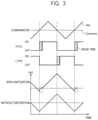
- FIG. 3 shows charts for schematically showing how distortion occurs in output current from the control apparatus according to the first embodiment.
- FIG. 4A is a diagram for illustrating how the control apparatus according to the first embodiment controls a fine movement stage.
- FIG. 4B is a diagram for illustrating how the control apparatus according to the first embodiment controls the fine movement stage.
- FIG. 5 shows charts for schematically showing drive profiles of a fine movement stage in an exposure apparatus including control apparatus according to a second embodiment of the present invention.
- FIG. 6 is a block diagram for illustrating one of the control apparatus according to the second embodiment.
- FIG. 7 is a top view for schematically illustrating a stage apparatus installed in an exposure apparatus including the control apparatus according to the first embodiment.
- FIG. 7 is a top view for schematically illustrating a stage apparatus 10 installed in an exposure apparatus including control apparatus 100 according to a first embodiment of the present invention.
- a direction extending from the back to the front of the drawing sheet is defined as a z-axis direction
- a direction extending perpendicularly to the z-axis direction toward the right side of the drawing sheet is defined as an x-axis direction
- a direction extending perpendicularly to the z-axis direction and the x-axis direction toward the upper side of the drawing sheet is defined as a y-axis direction.
- the stage apparatus 10 includes a y coarse movement stage 11 , a fine movement stage 14 , and an x coarse movement stage 15 .
- the y coarse movement stage 11 is driven along the y-axis direction with use of a surface plate 12 having a mirror-finished guide surface for the y coarse movement stage 11 , a yaw guide 13 , and a static pressure guide (not shown).
- the x coarse movement stage 15 is provided to sandwich, in the y-axis direction, the y coarse movement stage 11 with a static pressure guide (not shown) being provided on the surface plate 12 , and is driven in the x-axis direction along the y coarse movement stage 11 .
- a y coarse movement linear motor for driving the y coarse movement stage 11 includes movable elements 23 a and 23 b formed from coils.
- the y coarse movement stage 11 is connected to the y coarse movement linear motor via connecting plates 25 a and 25 b , and subjected to positioning control by a control system (not shown) and the y coarse movement linear motor.
- An x coarse movement linear motor for driving the x coarse movement stage 15 includes a stator 27 provided on the y coarse movement stage 11 and a movable element (not shown).
- the x coarse movement stage 15 is subjected to positioning control in the x-axis direction by the x coarse movement linear motor and a control system (not shown).
- the fine movement stage 14 is provided on the x coarse movement stage 15 .
- Fine movement x linear motors 31 a and 31 b configured to generate driving force in the x-axis direction
- fine movement y linear motors 32 a and 32 b configured to generate driving force in the y-axis direction are provided between the x coarse movement stage 15 and the fine movement stage 14 .
- fine movement z linear motors 33 a , 33 b , 33 c , and 33 d configured to generate driving force in the z-axis direction are provided between the x coarse movement stage 15 and the fine movement stage 14 .
- those fine movement linear motors are driven on an axis basis by separate control apparatus 100 , to thereby enable positioning control on the fine movement stage 14 along six axes (x axis, y axis, z axis, and rotational directions around those axes).
- FIG. 1 is a block diagram for illustrating one of the control apparatus 100 according to the first embodiment.
- the control apparatus 100 includes an amplifier (current source) 20 , a controller (control unit) 50 , and a detector (first detection unit) 70 .
- the amplifier 20 is configured to output current Iout for driving a linear motor LM (driving unit) for the fine movement stage 14 .
- the linear motors LM correspond to any one of the fine movement x linear motor, the fine movement y linear motor, and the fine movement z linear motor.
- the detector 70 is configured to detect a position (driving state) of the fine movement stage 14
- the controller 50 is configured to transmit a command value Command to the amplifier 20 based on a result of the detection by the detector 70 .
- a switching controller 20 a is configured to switch on one of two combinations, that is, a first combination of switching circuits H 1 and L 2 and a second combination of switching circuits H 2 and L 1 , and switch off the other combination in accordance with the transmitted command value Command and a reference triangular wave Wst.
- the amplifier 20 adopts a PWM method.
- desired current Iout can be output, which has a ripple waveform having frequency components corresponding to a frequency Fsw of the reference wave Wst as shown in FIG. 2A .
- the generated through-current causes heat generation and breakdown of the switching circuits H 1 , H 2 , L 1 , and L 2 .
- Such through-current may be possibly generated upon turning on one combination switched from the other combination.
- the generation of the through-current can be suppressed by setting a period in which the first combination of switching circuits H 1 and L 2 and the second combination of switching circuits H 2 and L 1 are both turned off, that is, a dead time.
- This configuration is generally used in the PWM method.
- the command value Command is changed with respect to the reference triangular wave Wst, to thereby offset current to be output from the amplifier 20 .
- distortion occurs when a reference value of a driver matches any value on and around an inflection point of the current change at which the dead time is generated.
- desired offset current is required in settling of the fine movement stage 14 , for example, because of disturbance caused by other components of magnets used in the fine movement linear motors and by installation of cables.
- FIG. 3 shows charts for schematically showing how distortion occurs in the output current Iout from the control apparatus 100 .
- a predetermined dead time is set before switching an off state to an on state so as to suppress generation of the through-current described above.
- This output current is represented by Iout_dist.
- Iout_dist the current Iout of a waveform having distortion at portions as indicated by Iout_dist in FIG. 2B is output.
- FIG. 4A and FIG. 4B are diagrams for illustrating how to control the fine movement x linear motors 31 a and 31 b configured to generate driving force for the fine movement stage 14 in the x-axis direction, and the fine movement y linear motors 32 a and 32 b configured to generate driving force for the fine movement stage 14 in the y-axis direction.
- separate amplifiers 20 are provided for the fine movement x linear motors 31 a and 31 b and the fine movement y linear motors 32 a and 32 b , and caused to output currents Ixf, Ixb, Iyl, and Iyr by the controller 50 .
- predetermined thrust force is required in the x-axis direction and the y-axis direction so as to control the fine movement stage 14 in a predetermined position in the rotational direction.
- the thrust force is proportional to a total value of control currents for the linear motors from the plurality of amplifiers 20 .
- this total value Istage can be represented by the vector sum of the currents Ixf, Ixb, Iyl, and Iyr.
- the distortion-involved output current Iout_dist (predetermined value) as described above is measured in advance in a corresponding amplifier 20 , and stored in the controller 50 .
- the fine movement stage 14 is disadvantageously controlled with a delay due to the distortion of the output current Iout from the amplifier 20 . As a result, an accuracy of positional control on the fine movement stage 14 is lowered.
- offset current Iadd is added to each of the currents Ixf, Ixb, Iyl, and Iyr for the fine movement x linear motors 31 a and 31 b and the fine movement y linear motors 32 a and 32 b while maintaining the total value Istage.
- the fine movement stage 14 can be controlled with high accuracy by changing current required in settling of the fine movement stage 14 in accordance with the distortion-involved output current of a corresponding amplifier 20 .
- the distortion-involved output current Iout_dist of a corresponding amplifier 20 can be changed as well in accordance with the current required in settling of the fine movement stage 14 .
- the distortion-involved output current Iout_dist of a corresponding amplifier 20 can be varied through changing the settings of the amplifier 20 (for example, changing the dead time, the switching frequency Fsw, or filter constant).
- the current required in settling of the fine movement stage 14 can be changed by changing a distance between the fine movement stage 14 and the x coarse movement stage 15 .
- FIG. 5 shows charts for showing drive profiles of the fine movement stage 14 in an exposure apparatus including control apparatus 200 according to the second embodiment.
- the fine movement stage 14 is driven with accelerated driving, constant-velocity driving, and decelerated driving being switched.
- the exposure apparatus performs exposure during the constant-velocity driving of the fine movement stage 14 , and hence highly accurate positional control is required for the fine movement stage 14 during the constant-velocity driving.
- the current required to drive the fine movement stage 14 varies for the accelerated driving, the constant-velocity driving, and the decelerated driving, and thus changes constantly upon switching the accelerated driving, the constant-velocity driving, and the decelerated driving.
- predetermined current is required in the accelerated driving just before the constant-velocity driving, and the required current is reduced in a constant-velocity drive section.
- the error Stage error increases due to the effect of the distortion-involved output current Iout_dist of the output current Iout from the amplifier 20 , and disadvantageously affects the accuracy of controlling the fine movement stage 14 in the constant-velocity drive section.
- FIG. 6 is a control block diagram for illustrating one of control apparatus 200 according to the second embodiment.
- a monitor 30 (second detection unit) is provided to monitor the output current Iout from a corresponding amplifier 20 .
- a compensation current source 40 is caused to supply the offset current Iadd so as to compensate for the output current Iout.
- control apparatus 200 can prevent the error of the fine movement stage 14 from increasing due to the distortion-involved output current Iout_dist by feedback control of the output current Iout from a corresponding amplifier 20 . Therefore, the accuracy of controlling the fine movement stage 14 can be maintained.
- the feedback control of the output current Iout is performed.
- this feedback control can be also performed by changing a control gain (not shown) and compensating for the output current Iout with the gain.
- the feedback control is performed so as to compensate for the output current in accordance with the distortion-involved output current of a corresponding amplifier 20 .
- the fine movement stage 14 can be controlled with high accuracy.
- the distortion-involved output current Iout_dist of a corresponding amplifier 20 can also be changed in accordance with current required in the drive section of the fine movement stage 14 .
- the distortion-involved output current Iout_dist of a corresponding amplifier 20 can be varied through changing the settings of the amplifier 20 (for example, changing the control gain in the amplifier 20 ).
- the current required in the drive section of the fine movement stage 14 can be changed as well through changing the distance between the fine movement stage 14 and the x coarse movement stage 15 .
- the control apparatus 200 is also applicable to a case in which the required current and the distortion-involved output current Iout_dist of a corresponding amplifier 20 match or affect each other even after the settling of the fine movement stage 14 .
- the output current Iout from a corresponding amplifier 20 is subjected to feedback control, but the present invention is not limited thereto.
- the fine movement stage 14 can be controlled with high accuracy by feedforward control of the output current Iout from a corresponding amplifier 20 to reduce any effect of the distortion.
- a manufacturing method for a device for example, semiconductor integrated circuit element or liquid crystal display element as an article includes a step of forming a pattern on a substrate (wafer, glass plate, or film-like substrate) with use of the exposure apparatus including the control apparatus described above.
- the manufacturing method may further include a step of developing the substrate having formed thereon the pattern, and a step of etching certain portions of the substrate.
- the manufacturing method may include executing, instead of etching, other processing such as processing of the substrate on which the pattern is formed.
- the manufacturing method for an article of the embodiment is advantageous in terms of at least one of performance, quality, yield, and production costs of the article as compared with related-art methods.
- control apparatus with which driving of the driving unit can be controlled with high accuracy with a simple configuration, the exposure apparatus, and the manufacturing method for an article can be provided.
Landscapes
- Physics & Mathematics (AREA)
- General Physics & Mathematics (AREA)
- Engineering & Computer Science (AREA)
- Power Engineering (AREA)
- Exposure And Positioning Against Photoresist Photosensitive Materials (AREA)
- Control Of Ac Motors In General (AREA)
- Control Of Multiple Motors (AREA)
Abstract
Description
Claims (17)
Applications Claiming Priority (3)
| Application Number | Priority Date | Filing Date | Title |
|---|---|---|---|
| JP2019013061A JP2020124010A (en) | 2019-01-29 | 2019-01-29 | Control device, exposure apparatus, and item production method |
| JP2019-013061 | 2019-01-29 | ||
| JPJP2019-013061 | 2019-01-29 |
Publications (2)
| Publication Number | Publication Date |
|---|---|
| US20200241430A1 US20200241430A1 (en) | 2020-07-30 |
| US11231655B2 true US11231655B2 (en) | 2022-01-25 |
Family
ID=71731236
Family Applications (1)
| Application Number | Title | Priority Date | Filing Date |
|---|---|---|---|
| US16/751,813 Active US11231655B2 (en) | 2019-01-29 | 2020-01-24 | Control apparatus, exposure apparatus, and manufacturing method for article |
Country Status (4)
| Country | Link |
|---|---|
| US (1) | US11231655B2 (en) |
| JP (1) | JP2020124010A (en) |
| KR (1) | KR20200094109A (en) |
| CN (1) | CN111487847A (en) |
Citations (17)
| Publication number | Priority date | Publication date | Assignee | Title |
|---|---|---|---|---|
| US20040201834A1 (en) * | 2002-08-29 | 2004-10-14 | Canon Kabushiki Kaisha | Stage apparatus and its driving method, exposure apparatus and device manufacturing method |
| US20060170888A1 (en) * | 2005-01-31 | 2006-08-03 | Canon Kabushiki Kaisha | Moving control apparatus and moving control method |
| US20080266907A1 (en) * | 2007-04-25 | 2008-10-30 | Jin-Tae Kim | Switch controller, switch control method, converter using the same, and driving method thereof |
| US20130026924A1 (en) * | 2011-01-28 | 2013-01-31 | Seoul Semiconductor Co., Ltd. | Led driving circuit package |
| JP2013031204A (en) | 2012-09-12 | 2013-02-07 | Renesas Electronics Corp | Pwm amplifier |
| US20150103328A1 (en) * | 2013-10-16 | 2015-04-16 | Canon Kabushiki Kaisha | Lithography apparatus, power supplying method, and article manufacturing method |
| US20150303841A1 (en) * | 2014-04-18 | 2015-10-22 | Canon Kabushiki Kaisha | Linear motor control apparatus and linear motor control system |
| US20160373045A1 (en) * | 2015-06-16 | 2016-12-22 | Canon Kabushiki Kaisha | Motor driving device for controlling motor with pulse signal |
| US20160381773A1 (en) * | 2015-06-23 | 2016-12-29 | Panasonic Intellectual Property Management Co., Ltd. | Semiconductor light source driving apparatus |
| US20170077712A1 (en) * | 2014-03-27 | 2017-03-16 | Autonetworks Technologies, Ltd. | Power source control device and power source control method |
| US20170288589A1 (en) * | 2016-03-30 | 2017-10-05 | Canon Kabushiki Kaisha | Motor driving apparatus, sheet conveyance apparatus, document feeding apparatus, document reading apparatus and image forming apparatus |
| US20180254733A1 (en) * | 2017-03-01 | 2018-09-06 | Canon Kabushiki Kaisha | Control device and control method |
| US20180301977A1 (en) * | 2017-04-14 | 2018-10-18 | Renesas Electronics Corporation | Semiconductor device and control method thereof |
| US20190193975A1 (en) * | 2017-12-22 | 2019-06-27 | Seiko Epson Corporation | Recording device and control method for recording device |
| US20200012200A1 (en) * | 2018-07-04 | 2020-01-09 | Canon Kabushiki Kaisha | Control apparatus, exposure apparatus, and method of manufacturing article |
| US20200028457A1 (en) * | 2018-07-20 | 2020-01-23 | Minebea Mitsumi Inc. | Motor driving control device and motor driving control method |
| US20200266732A1 (en) * | 2019-02-14 | 2020-08-20 | Minebea Mitsumi Inc. | Motor driving control device and motor driving control method |
Family Cites Families (2)
| Publication number | Priority date | Publication date | Assignee | Title |
|---|---|---|---|---|
| JP3073879B2 (en) * | 1994-03-25 | 2000-08-07 | キヤノン株式会社 | Anti-vibration device |
| JP2003037986A (en) * | 2001-07-25 | 2003-02-07 | Nikon Corp | Motor driving device, stage device, and exposure apparatus having the same |
-
2019
- 2019-01-29 JP JP2019013061A patent/JP2020124010A/en not_active Withdrawn
-
2020
- 2020-01-20 CN CN202010061877.7A patent/CN111487847A/en active Pending
- 2020-01-24 US US16/751,813 patent/US11231655B2/en active Active
- 2020-01-29 KR KR1020200010200A patent/KR20200094109A/en not_active Ceased
Patent Citations (17)
| Publication number | Priority date | Publication date | Assignee | Title |
|---|---|---|---|---|
| US20040201834A1 (en) * | 2002-08-29 | 2004-10-14 | Canon Kabushiki Kaisha | Stage apparatus and its driving method, exposure apparatus and device manufacturing method |
| US20060170888A1 (en) * | 2005-01-31 | 2006-08-03 | Canon Kabushiki Kaisha | Moving control apparatus and moving control method |
| US20080266907A1 (en) * | 2007-04-25 | 2008-10-30 | Jin-Tae Kim | Switch controller, switch control method, converter using the same, and driving method thereof |
| US20130026924A1 (en) * | 2011-01-28 | 2013-01-31 | Seoul Semiconductor Co., Ltd. | Led driving circuit package |
| JP2013031204A (en) | 2012-09-12 | 2013-02-07 | Renesas Electronics Corp | Pwm amplifier |
| US20150103328A1 (en) * | 2013-10-16 | 2015-04-16 | Canon Kabushiki Kaisha | Lithography apparatus, power supplying method, and article manufacturing method |
| US20170077712A1 (en) * | 2014-03-27 | 2017-03-16 | Autonetworks Technologies, Ltd. | Power source control device and power source control method |
| US20150303841A1 (en) * | 2014-04-18 | 2015-10-22 | Canon Kabushiki Kaisha | Linear motor control apparatus and linear motor control system |
| US20160373045A1 (en) * | 2015-06-16 | 2016-12-22 | Canon Kabushiki Kaisha | Motor driving device for controlling motor with pulse signal |
| US20160381773A1 (en) * | 2015-06-23 | 2016-12-29 | Panasonic Intellectual Property Management Co., Ltd. | Semiconductor light source driving apparatus |
| US20170288589A1 (en) * | 2016-03-30 | 2017-10-05 | Canon Kabushiki Kaisha | Motor driving apparatus, sheet conveyance apparatus, document feeding apparatus, document reading apparatus and image forming apparatus |
| US20180254733A1 (en) * | 2017-03-01 | 2018-09-06 | Canon Kabushiki Kaisha | Control device and control method |
| US20180301977A1 (en) * | 2017-04-14 | 2018-10-18 | Renesas Electronics Corporation | Semiconductor device and control method thereof |
| US20190193975A1 (en) * | 2017-12-22 | 2019-06-27 | Seiko Epson Corporation | Recording device and control method for recording device |
| US20200012200A1 (en) * | 2018-07-04 | 2020-01-09 | Canon Kabushiki Kaisha | Control apparatus, exposure apparatus, and method of manufacturing article |
| US20200028457A1 (en) * | 2018-07-20 | 2020-01-23 | Minebea Mitsumi Inc. | Motor driving control device and motor driving control method |
| US20200266732A1 (en) * | 2019-02-14 | 2020-08-20 | Minebea Mitsumi Inc. | Motor driving control device and motor driving control method |
Also Published As
| Publication number | Publication date |
|---|---|
| JP2020124010A (en) | 2020-08-13 |
| KR20200094109A (en) | 2020-08-06 |
| US20200241430A1 (en) | 2020-07-30 |
| CN111487847A (en) | 2020-08-04 |
Similar Documents
| Publication | Publication Date | Title |
|---|---|---|
| US8849456B2 (en) | Robot, carriage device, and control method using inertia sensor | |
| US9715124B2 (en) | Control device, actuator including control device, image blur correction device, interchangeable lens, image pickup apparatus, and automatic stage | |
| EP3118985B1 (en) | Control apparatus of vibration actuator, method for controlling vibration actuator, driving apparatus, and imaging apparatus | |
| JP6667220B2 (en) | Vibration-type actuator control device and control method, drive device, imaging device, and automatic stage | |
| JPWO2014167808A1 (en) | Motor drive device | |
| JP2015033240A (en) | Linear motor system | |
| CN111193402B (en) | Digital control system and method of DC-DC power supply | |
| US11231655B2 (en) | Control apparatus, exposure apparatus, and manufacturing method for article | |
| CN108233815A (en) | A kind of voice coil motor high speed and precision light beam pointing system control method based on PWM | |
| CN101496275A (en) | Drive and method | |
| EP2869121B1 (en) | Computer-readable storage medium, generating method, generating apparatus, driving apparatus, processing apparatus, lithography apparatus, and method of manufacturing article | |
| US11652435B2 (en) | Command generation device and command generation method | |
| JP2002163006A (en) | Motor control device and control method | |
| JP6971785B2 (en) | Drives, their control methods, and programs, as well as electronics. | |
| JP2004094368A (en) | Control method for servo system and its controller | |
| CN111865140A (en) | A method and implementation device for reducing motor tracking error based on micro-drive unit | |
| JP5055932B2 (en) | Synchronous motor controller | |
| CN113054888B (en) | Motor control device and motor control method | |
| JP7467201B2 (en) | Motor Control Device | |
| JPS6132120A (en) | Positioning control system | |
| KR0160745B1 (en) | Method for twin-x-y robot control | |
| Mirtchev et al. | Optimizing the feedback control of Galvo scanners for laser manufacturing systems | |
| KR0160680B1 (en) | Control method for twin x-y coordinate robot when it returns to origin | |
| JPH06276774A (en) | Positioning control method for motor | |
| JP2006288029A (en) | Vehicle motor current control apparatus and motor current control method |
Legal Events
| Date | Code | Title | Description |
|---|---|---|---|
| FEPP | Fee payment procedure |
Free format text: ENTITY STATUS SET TO UNDISCOUNTED (ORIGINAL EVENT CODE: BIG.); ENTITY STATUS OF PATENT OWNER: LARGE ENTITY |
|
| AS | Assignment |
Owner name: CANON KABUSHIKI KAISHA, JAPAN Free format text: ASSIGNMENT OF ASSIGNORS INTEREST;ASSIGNOR:MOTEGI, TAKESHI;REEL/FRAME:052374/0680 Effective date: 20200108 |
|
| STPP | Information on status: patent application and granting procedure in general |
Free format text: RESPONSE TO NON-FINAL OFFICE ACTION ENTERED AND FORWARDED TO EXAMINER |
|
| STPP | Information on status: patent application and granting procedure in general |
Free format text: FINAL REJECTION MAILED |
|
| STPP | Information on status: patent application and granting procedure in general |
Free format text: NOTICE OF ALLOWANCE MAILED -- APPLICATION RECEIVED IN OFFICE OF PUBLICATIONS |
|
| STPP | Information on status: patent application and granting procedure in general |
Free format text: DOCKETED NEW CASE - READY FOR EXAMINATION |
|
| STPP | Information on status: patent application and granting procedure in general |
Free format text: NOTICE OF ALLOWANCE MAILED -- APPLICATION RECEIVED IN OFFICE OF PUBLICATIONS |
|
| STPP | Information on status: patent application and granting procedure in general |
Free format text: PUBLICATIONS -- ISSUE FEE PAYMENT VERIFIED |
|
| STCF | Information on status: patent grant |
Free format text: PATENTED CASE |
|
| FEPP | Fee payment procedure |
Free format text: MAINTENANCE FEE REMINDER MAILED (ORIGINAL EVENT CODE: REM.); ENTITY STATUS OF PATENT OWNER: LARGE ENTITY |