US11231069B2 - Wheel hub bearing provided with a wireless power transfer device - Google Patents
Wheel hub bearing provided with a wireless power transfer device Download PDFInfo
- Publication number
- US11231069B2 US11231069B2 US17/063,071 US202017063071A US11231069B2 US 11231069 B2 US11231069 B2 US 11231069B2 US 202017063071 A US202017063071 A US 202017063071A US 11231069 B2 US11231069 B2 US 11231069B2
- Authority
- US
- United States
- Prior art keywords
- wheel hub
- coil
- shield
- hub bearing
- emitting
- Prior art date
- Legal status (The legal status is an assumption and is not a legal conclusion. Google has not performed a legal analysis and makes no representation as to the accuracy of the status listed.)
- Active
Links
Images


Classifications
-
- F—MECHANICAL ENGINEERING; LIGHTING; HEATING; WEAPONS; BLASTING
- F16—ENGINEERING ELEMENTS AND UNITS; GENERAL MEASURES FOR PRODUCING AND MAINTAINING EFFECTIVE FUNCTIONING OF MACHINES OR INSTALLATIONS; THERMAL INSULATION IN GENERAL
- F16C—SHAFTS; FLEXIBLE SHAFTS; ELEMENTS OR CRANKSHAFT MECHANISMS; ROTARY BODIES OTHER THAN GEARING ELEMENTS; BEARINGS
- F16C19/00—Bearings with rolling contact, for exclusively rotary movement
- F16C19/02—Bearings with rolling contact, for exclusively rotary movement with bearing balls essentially of the same size in one or more circular rows
- F16C19/14—Bearings with rolling contact, for exclusively rotary movement with bearing balls essentially of the same size in one or more circular rows for both radial and axial load
- F16C19/18—Bearings with rolling contact, for exclusively rotary movement with bearing balls essentially of the same size in one or more circular rows for both radial and axial load with two or more rows of balls
- F16C19/181—Bearings with rolling contact, for exclusively rotary movement with bearing balls essentially of the same size in one or more circular rows for both radial and axial load with two or more rows of balls with angular contact
- F16C19/183—Bearings with rolling contact, for exclusively rotary movement with bearing balls essentially of the same size in one or more circular rows for both radial and axial load with two or more rows of balls with angular contact with two rows at opposite angles
- F16C19/184—Bearings with rolling contact, for exclusively rotary movement with bearing balls essentially of the same size in one or more circular rows for both radial and axial load with two or more rows of balls with angular contact with two rows at opposite angles in O-arrangement
-
- B—PERFORMING OPERATIONS; TRANSPORTING
- B60—VEHICLES IN GENERAL
- B60B—VEHICLE WHEELS; CASTORS; AXLES FOR WHEELS OR CASTORS; INCREASING WHEEL ADHESION
- B60B27/00—Hubs
- B60B27/0094—Hubs one or more of the bearing races are formed by the hub
-
- B—PERFORMING OPERATIONS; TRANSPORTING
- B60—VEHICLES IN GENERAL
- B60B—VEHICLE WHEELS; CASTORS; AXLES FOR WHEELS OR CASTORS; INCREASING WHEEL ADHESION
- B60B27/00—Hubs
- B60B27/0005—Hubs with ball bearings
-
- B—PERFORMING OPERATIONS; TRANSPORTING
- B60—VEHICLES IN GENERAL
- B60B—VEHICLE WHEELS; CASTORS; AXLES FOR WHEELS OR CASTORS; INCREASING WHEEL ADHESION
- B60B27/00—Hubs
- B60B27/0047—Hubs characterised by functional integration of other elements
- B60B27/0068—Hubs characterised by functional integration of other elements the element being a sensor
-
- B—PERFORMING OPERATIONS; TRANSPORTING
- B60—VEHICLES IN GENERAL
- B60C—VEHICLE TYRES; TYRE INFLATION; TYRE CHANGING; CONNECTING VALVES TO INFLATABLE ELASTIC BODIES IN GENERAL; DEVICES OR ARRANGEMENTS RELATED TO TYRES
- B60C23/00—Devices for measuring, signalling, controlling, or distributing tyre pressure or temperature, specially adapted for mounting on vehicles; Arrangement of tyre inflating devices on vehicles, e.g. of pumps or of tanks; Tyre cooling arrangements
- B60C23/02—Signalling devices actuated by tyre pressure
- B60C23/04—Signalling devices actuated by tyre pressure mounted on the wheel or tyre
- B60C23/0408—Signalling devices actuated by tyre pressure mounted on the wheel or tyre transmitting the signals by non-mechanical means from the wheel or tyre to a vehicle body mounted receiver
- B60C23/041—Means for supplying power to the signal- transmitting means on the wheel
- B60C23/0413—Wireless charging of active radio frequency circuits
-
- H—ELECTRICITY
- H02—GENERATION; CONVERSION OR DISTRIBUTION OF ELECTRIC POWER
- H02J—ELECTRIC POWER NETWORKS; CIRCUIT ARRANGEMENTS OR SYSTEMS FOR SUPPLYING OR DISTRIBUTING ELECTRIC POWER; SYSTEMS FOR STORING ELECTRIC ENERGY
- H02J50/00—Circuit arrangements or systems for wireless supply or distribution of electric power
- H02J50/10—Circuit arrangements or systems for wireless supply or distribution of electric power using inductive coupling
- H02J50/12—Circuit arrangements or systems for wireless supply or distribution of electric power using inductive coupling of the resonant type
-
- H—ELECTRICITY
- H02—GENERATION; CONVERSION OR DISTRIBUTION OF ELECTRIC POWER
- H02J—ELECTRIC POWER NETWORKS; CIRCUIT ARRANGEMENTS OR SYSTEMS FOR SUPPLYING OR DISTRIBUTING ELECTRIC POWER; SYSTEMS FOR STORING ELECTRIC ENERGY
- H02J50/00—Circuit arrangements or systems for wireless supply or distribution of electric power
- H02J50/70—Circuit arrangements or systems for wireless supply or distribution of electric power involving the reduction of electric, magnetic or electromagnetic leakage fields
-
- B—PERFORMING OPERATIONS; TRANSPORTING
- B60—VEHICLES IN GENERAL
- B60B—VEHICLE WHEELS; CASTORS; AXLES FOR WHEELS OR CASTORS; INCREASING WHEEL ADHESION
- B60B2310/00—Manufacturing methods
- B60B2310/30—Manufacturing methods joining
- B60B2310/316—Manufacturing methods joining by press-fitting, shrink-fitting
-
- B—PERFORMING OPERATIONS; TRANSPORTING
- B60—VEHICLES IN GENERAL
- B60B—VEHICLE WHEELS; CASTORS; AXLES FOR WHEELS OR CASTORS; INCREASING WHEEL ADHESION
- B60B2900/00—Purpose of invention
- B60B2900/50—Improvement of
- B60B2900/541—Servicing
-
- F—MECHANICAL ENGINEERING; LIGHTING; HEATING; WEAPONS; BLASTING
- F16—ENGINEERING ELEMENTS AND UNITS; GENERAL MEASURES FOR PRODUCING AND MAINTAINING EFFECTIVE FUNCTIONING OF MACHINES OR INSTALLATIONS; THERMAL INSULATION IN GENERAL
- F16C—SHAFTS; FLEXIBLE SHAFTS; ELEMENTS OR CRANKSHAFT MECHANISMS; ROTARY BODIES OTHER THAN GEARING ELEMENTS; BEARINGS
- F16C2326/00—Articles relating to transporting
- F16C2326/01—Parts of vehicles in general
- F16C2326/02—Wheel hubs or castors
Definitions
- the present invention relates to a wheel hub bearing provided with a wireless power transfer device.
- Wheel hub bearing provided with a bearing unit for rotatably supporting a vehicle wheel on a suspension are known and commonly used.
- the bearing unit typically includes a pair of rolling bearings.
- the current state of the art also comprises so called “smart” wheels or tires, provided with sensors, for example, tire pressure monitoring system (TPMS).
- sensors for example, tire pressure monitoring system (TPMS).
- TPMS tire pressure monitoring system
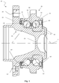
- FIG. 1 is a cross-section of a wheel hub bearing, according to an embodiment of the present invention.
- FIG. 2 is an enlarged detail of the flanged hub and the bearing unit of FIG. 1 , schematically showing the wireless power transfer device, according to the invention.
- FIG. 3 is a further more enlarged detail schematically showing the magnetic field of the wireless power transfer device of FIG. 2 .
- TPMS battery powered systems
- the solution for sensor such as TPMS is to use a battery and low consumption electronic circuits and processors. Battery life limits the amount of sensor data that can be collected and/or data transmitted. A result is that the real time capabilities of sensors are drastically reduced in order to preserve a battery life of at most three years.
- the wheel hub bearing is links the stationary chassis, wherein a battery can be accommodated, to the tire and its sensors dispose on a rotating wheel. Therefore, a wheel hub bearing is the perfect location to embed a wireless energy transfer device capable of providing a reliable power source to smart wheels and/or tires.
- a first part of an electronic can be attached to a non-rotating part of the wheel hub bearing (e.g., outer ring, seal or knuckle) and a second part of an electronic can be attached to a rotating part of the bearing (e.g., small inner ring, flanged inner ring, seal flinger or magnetic encoder).
- Embodiments in accordance with this disclosure relate to an improved wireless power transfer device assembled on the wheel hub bearing and provided with a pair of rolling bearings for rotatably supporting a vehicle wheel on a suspension.
- Such applications include both the case where the outer ring of the bearings is rotatable while the inner rings of the bearing are fixed, and the opposite case in which the inner rings rotate and the outer ring is fixed.
- Various embodiments are also suitable for any type of rolling bodies (balls, rollers, tapered rollers, etc.). By way of non-limiting example, embodiments will now be described with reference to a wheel hub bearing for motor vehicles provided with a bearing unit.
- a wheel hub bearing according to a preferred embodiment of the invention is indicated as a whole with 10 .
- the figure shows a detail of the exemplifying configuration.
- a wheel hub bearing 10 has a central rotation axis X and comprises a hub 20 preferably, but not necessarily, rotatable, and a bearing unit 30 , which in turn comprises:
- the radially outer ring 31 is provided with two respective radially outer raceways 31 ′, while the radially inner rings 20 , 34 are provided with respective radially inner raceways 20 ′, 34 ′ to allow the rotation of the rolling bodies row 32 , axially outer, interposed between the radially outer ring 31 and the hub 20 , and the rolling bodies row 33 , axially inner, between the radially outer ring 31 and the radially inner ring 34 .
- the references 32 , 33 will be attributed both to the individual balls and to the ball rows.
- the term “ball” can be used in an exemplary manner in the present description and in the accompanying drawings in place of the more generic term “rolling body” (and the same numerical references will also be used).
- Hub 20 defines in its axially inner end a rolled edge 22 , which is configured for axially preloading inner ring 34 .
- Hub 20 also has an axially outer flange portion 23 .
- Flange portion has a plurality of axial fixing holes 24 . These holes are seats for the same number of fixing means (for example stud bolts, not shown in the figure) which connect an element of the motor vehicle wheel, for example the non-driven wheel or the brake disc (also of the known type and not shown in the figure), to hub 20 .
- Wheel hub bearing 10 is also provided with sealing means 50 for sealing such a bearing unit from the external environment. Moreover, a wheel hub bearing may also be provided with devices for detecting a parameter of a motor vehicle, for example the speed of rotation of rotating ring 34 of bearing unit 30 . In an example encoder 60 is provided, as shown in FIG. 1 .
- a wireless power transfer is provided.
- An emitting electronic is assembled on a radially outer ring 31
- a receiving electronic is disposed on a flanged inner ring or hub 20 .
- a radially outer ring, e.g, 31 , a flanged inner ring or hub 20 , and an emitting coil 70 and a receiving coil 71 are configured such that emitting coil 70 and receiving coil 71 are axially spaced by a first airgap G 1 smaller than 1.5 mm.
- airgap G 1 is between 0.1 and 1.5 mm.
- airgap G 1 is less than 0.1 mm but not nonexistent.
- an emitting electronic comprises an emitting coil 70 , made of copper wires and attached to a ferromagnetic shield 80 .
- Shield 80 must preferably have a high magnetic permeability and a low electric conductivity in order to minimize magnetic loss.
- shield must be made of metallic material and especially ferromagnetic material. Aluminium or plastic material must be avoided.
- composite materials plastic/ferrite are viable and within the scope of this disclosure.
- an emitting coil is protected from the environment by an impregnation of a protective and electrically insulated resin or by overmolding with plastic or rubber.
- a coil can be directly soldered to the cable wire.
- a coil can be crimped to a cable wire using a deformable metallic tube.
- a emitting coil 70 can be soldered or crimped to a conductive lead frame 100 .
- Lead frame 100 may be crimped or soldered to the cable wire of the power cable 90 .
- connections between emitting coil 70 to power cable 90 can be overmolded with shield 80 by an overmolding polymer 110 (for instance, a thermoplastic polymer or an elastomeric polymer) in order to create a unique and robust unit.
- an overmolding polymer 110 for instance, a thermoplastic polymer or an elastomeric polymer
- a coil can also be overmolded, however the thickness of plastic at the surface of the coil has to be minimal to optimize an airgap between the two coils.
- An emitting electronic is preferably press-fitted to a radially outer ring, e.g., 31 in order to interlock it to a non-rotating element of a bearing unit, e.g., 30 . Assembly occurs after press fitting on the outer ring of a seal 50 .
- An emitting electronic can also be assembled to a radially outer ring 31 in any other suitable way.
- An emitting coil is preferably connected to an oscillator electric circuit (known and therefore not shown in the figure) that converts DC voltage from a battery (usually between 8V to 15V for passenger vehicle) to AC voltage to create an inductive effect.
- This conversation can be also done in any suitable way.
- Oscillator electric circuit or more in general, an electronic can be embedded between emitting coil 70 and power cable 90 in the overmolded volume. In alternative, this electronic can be accommodated in any other part of the electric circuit outside the bearing and wheel volume.
- the receiving electronic has the same design, and therefore comprises a receiving coil 71 and a shield 81 , holding the coil. Shield 81 used to attach a coil is also used as seal contact surface flinger.
- receiving coil 71 can be glued or overmolded and a cable connection to flat cable 91 is done the same way as for emitting coil 70 .
- receiving coil 71 can be soldered or crimped to a conductive lead frame (not shown in FIG. 2 ). Lead frame 101 is crimped or soldered to the cable wire of flat cable 91 .
- connection between a receiving coil 71 and a flat cable 91 can be overmolded with the shield 81 by an overmolding polymer 111 (for instance, a thermoplastic polymer or an elastomeric polymer) in order to create a unique and robust unit.
- an overmolding polymer 111 for instance, a thermoplastic polymer or an elastomeric polymer
- This receiving electronic is press-fitted on a hub, e.g., 20 before the assembly of the bearing.
- coils are outside the sealing area in order to avoid any additional holes in a bearing or sealing solution in order to maintain optimal bearing robustness against contamination.
- a coil may be protected by a resin/polymer (non-conductive) in order to sustain the environment.
- a shield is designed in order to maintain the same seal interface as in the state of the art for seals.
- a receiving coil 71 gets an AC signal that can be converted to a DC voltage using a rectifier circuit. Such conversion can be realized by electronic devices that may be embedded in a wheel sensor or tire sensors.
- shields 80 , 81 Particular attention must be provided in designing shields 80 , 81 . To get a strong magnetic circuit, shield shape is really important.
- assembly and the shape of shields are done with three purposes:
- the small length of the two airgap G 2 and G 3 has the main purpose of concentrating the magnetic field into a loop around both coils. On the other hand, such small length has also the advantages of avoiding or at least reducing as much as possible the contamination inside the bearing unit.
- the minimum value of the airgap G 2 , G 3 is determined by the tolerance of the components and by the deflection of the elements during cornering. To improve such a minimum value, on both hub 20 and radially outer ring 31 , the contact surfaces of the shield can be machined to reduce the tolerance. A further improvement can be obtained by shaping the shields so that they are rigid enough to reduce oscillation during working condition.
- one of the circuit can optionally have a resonant circuit in order to optimize the energy transmission for larger gaps between the rotating elements.
- the emitting and receiving circuit could have digital control and order to transmit digital information in addition of the power as it is done for smartphone charging station.
- This solution provide a reliable energy source and with high power capability (compared with standard battery systems). Car manufacturers or suppliers can design complex sensing system with advanced processing electronic on the rotating part without compromise respect to device service life.
- the system can be inside the bearing providing a seamless integration for the customer.
- the bearing is already using a cable system for the ABS sensor, the same cabling route could be used for the wheel sensors.
- a wheel hub bearing for motor vehicles is provided with a wireless power transfer device, producing a strong magnetic field and not affecting the standard layout of the known wheel hub bearing.
- the wheel hub bearing is equipped with a bearing unit comprising an outer ring, a pair of inner rings, of which the inner axially outer ring consists of the same hub while the inner axially inner ring is a separate element mounted on the hub, and a plurality of rolling bodies, for example balls.
- the flanged, rotatable hub is connected to a non-motive wheel of a motor vehicle.
- the technology can be inductive, inductive with or without a resonant circuit or capacitive.
- One part of the electronic is attached to the non-rotating part of the wheel hub bearing (outer ring, seal or Knuckle) and the second part of the electronic is attached to the rotating part of the bearing (small inner ring, flange inner ring, seal flinger or magnetic encoder).
- the exemplary embodiments herein are explained using an inductive solution, but upon reading this disclosure one will appreciate that inductive with or without a resonant circuit or capacitive solutions are equally within the scope of this disclosure.
- Cost-effective and efficient wireless power transfer devices have a very small distance between the emitting and the receiving power systems.
- the wheel hub bearing is the ideal location to ensure a small airgap thanks to the stiffness of the product and its accurate mechanical elements.
- both the emitting electronic and the receiving electronic comprise a copper coil attached to a ferromagnetic shield.
- the flinger must preferably have a high magnetic permeability and a low electric conductivity in order to minimize magnetic loss.
- the airgap between the ferromagnetic shields should be minimized and has to be smaller than 1.5 mm.
- the cabling solution allows not to create any additional holes in steel shield or bearing steel, thus avoiding any risk of contamination.
- a wheel hub bearing is provided with a wireless power transfer device having the characteristics set forth in the independent claim, annexed to the present description.
Landscapes
- Engineering & Computer Science (AREA)
- Mechanical Engineering (AREA)
- Computer Networks & Wireless Communication (AREA)
- Power Engineering (AREA)
- General Engineering & Computer Science (AREA)
- Physics & Mathematics (AREA)
- Electromagnetism (AREA)
- Rolling Contact Bearings (AREA)
Abstract
Description
-
- tire pressure monitoring system,
- tire wear monitoring system,
- tire load sensor,
- vibration monitoring,
- automatic inflation system,
- load sensing system on the rim.
-
- a radially
outer ring 31, preferably, but not necessarily, stationary, - a radially inner ring or flanged
inner ring 20 defined by thehub 20, - a further radially
internal ring 34 rotatable mounted on and integral with thehub 20; - two rows of
rolling bodies outer ring 31 and the radiallyinner rings - two
cages rolling bodies rows
- a radially
-
- to minimize an airgap between
coils - to create and maintain a good magnetic loop around the two coils. The shapes of the two shields that are supporting the coils are designed in order to have minimum airgap between ferromagnetic element and create a magnetic circuit. As shown in
FIG. 3 , a second airgap G2 and a third airgap G3 between theshields - to create a labyrinth in order to reduce contamination in the coil area.
- to minimize an airgap between
Claims (14)
Applications Claiming Priority (2)
| Application Number | Priority Date | Filing Date | Title |
|---|---|---|---|
| IT102019000019124 | 2019-10-17 | ||
| IT201900019124 | 2019-10-17 |
Publications (2)
| Publication Number | Publication Date |
|---|---|
| US20210115969A1 US20210115969A1 (en) | 2021-04-22 |
| US11231069B2 true US11231069B2 (en) | 2022-01-25 |
Family
ID=69469165
Family Applications (1)
| Application Number | Title | Priority Date | Filing Date |
|---|---|---|---|
| US17/063,071 Active US11231069B2 (en) | 2019-10-17 | 2020-10-05 | Wheel hub bearing provided with a wireless power transfer device |
Country Status (3)
| Country | Link |
|---|---|
| US (1) | US11231069B2 (en) |
| CN (1) | CN112677704A (en) |
| DE (1) | DE102020126372A1 (en) |
Families Citing this family (3)
| Publication number | Priority date | Publication date | Assignee | Title |
|---|---|---|---|---|
| JP7052366B2 (en) * | 2018-01-18 | 2022-04-12 | 横浜ゴム株式会社 | Tire information acquisition device |
| CN114294336B (en) * | 2021-12-14 | 2025-01-07 | 浙江博盟精工轴承有限公司 | Combined bearings and combined bearings with encoders |
| US20250286407A1 (en) * | 2024-03-05 | 2025-09-11 | Solace Power Inc. | Wireless power transfer in a bearing |
Citations (18)
| Publication number | Priority date | Publication date | Assignee | Title |
|---|---|---|---|---|
| US5898388A (en) | 1997-03-13 | 1999-04-27 | Fag Automobiltechnik Ag | Rolling contact bearing with rotational speed measuring device |
| US20020033638A1 (en) * | 2000-08-01 | 2002-03-21 | Ntn Corporation | Wheel support bearing assembly and anti-skid brake device using the same |
| US20020130655A1 (en) * | 2001-03-13 | 2002-09-19 | Ntn Corporation | Wheel support bearing assembly |
| US20050046559A1 (en) * | 2003-08-25 | 2005-03-03 | Siemens Vdo Automotive Corporation | Tire sensor communication system |
| US20050226545A1 (en) | 2004-04-09 | 2005-10-13 | Hisashi Ohtsuki | Wheel bearing apparatus incorporated with a wheel speed detecting apparatus |
| US20050258950A1 (en) * | 2002-09-09 | 2005-11-24 | Ntn Corporation | Wireless sensor system and bearing device having wireless sensor |
| US7262743B2 (en) * | 2001-11-09 | 2007-08-28 | Commissariat A L'energie Atomique | Passive device for increasing the transmission efficiency of radio-frequency systems |
| WO2008129787A1 (en) | 2007-03-30 | 2008-10-30 | Ntn Corporation | Bearing for wheel with communication function |
| EP2159578A1 (en) | 2007-06-08 | 2010-03-03 | JTEKT Corporation | Hub unit |
| US7878411B2 (en) * | 2004-07-29 | 2011-02-01 | Ntn Corporation | Wheel bearing device and its quality management method |
| KR20150109714A (en) | 2014-03-20 | 2015-10-02 | 주식회사 오토산업 | Wireless power transfer system for car wheel |
| US9584190B2 (en) * | 2013-06-26 | 2017-02-28 | Hyundai Motor Company | Vehicle driving system having wireless power transmission function and method thereof |
| US20170158012A1 (en) * | 2015-12-08 | 2017-06-08 | Aktiebolaget Skf | Strut mount bearing unit |
| JP2017106609A (en) | 2015-12-04 | 2017-06-15 | 日本精工株式会社 | Rolling bearing unit for wheel support |
| US20180006493A1 (en) | 2016-06-29 | 2018-01-04 | Wisconsin Alumni Research Foundation | High Power Transfer Through Load-Supporting Bearings |
| JP2018001769A (en) | 2016-06-27 | 2018-01-11 | 日本精工株式会社 | Rolling bearing unit for supporting wheel |
| WO2018038572A1 (en) | 2016-08-26 | 2018-03-01 | 주식회사 아모센스 | Power supply system for wheel mounted sensor using wireless power transmission scheme |
| US20190126677A1 (en) * | 2017-10-10 | 2019-05-02 | Aktiebolaget Skf | Wheel hub assembly having dual angular position sensors |
Family Cites Families (4)
| Publication number | Priority date | Publication date | Assignee | Title |
|---|---|---|---|---|
| JP5085173B2 (en) * | 2007-03-30 | 2012-11-28 | Ntn株式会社 | Wheel bearing with power transmission device |
| DE102014209022A1 (en) * | 2014-05-13 | 2015-11-19 | Schaeffler Technologies AG & Co. KG | wheel bearing unit |
| IT201600119828A1 (en) * | 2016-11-28 | 2018-05-28 | Skf Ab | VOLVENTIC BEARING WITH IMPROVED SEALING DEVICE |
| JP2019007597A (en) * | 2017-06-28 | 2019-01-17 | 株式会社ジェイテクト | Wheel bearing device |
-
2020
- 2020-10-05 US US17/063,071 patent/US11231069B2/en active Active
- 2020-10-08 DE DE102020126372.4A patent/DE102020126372A1/en active Pending
- 2020-10-12 CN CN202011082844.7A patent/CN112677704A/en active Pending
Patent Citations (20)
| Publication number | Priority date | Publication date | Assignee | Title |
|---|---|---|---|---|
| US5898388A (en) | 1997-03-13 | 1999-04-27 | Fag Automobiltechnik Ag | Rolling contact bearing with rotational speed measuring device |
| US20020033638A1 (en) * | 2000-08-01 | 2002-03-21 | Ntn Corporation | Wheel support bearing assembly and anti-skid brake device using the same |
| US20020130655A1 (en) * | 2001-03-13 | 2002-09-19 | Ntn Corporation | Wheel support bearing assembly |
| US7262743B2 (en) * | 2001-11-09 | 2007-08-28 | Commissariat A L'energie Atomique | Passive device for increasing the transmission efficiency of radio-frequency systems |
| US20050258950A1 (en) * | 2002-09-09 | 2005-11-24 | Ntn Corporation | Wireless sensor system and bearing device having wireless sensor |
| US20050046559A1 (en) * | 2003-08-25 | 2005-03-03 | Siemens Vdo Automotive Corporation | Tire sensor communication system |
| US7618194B2 (en) * | 2004-04-09 | 2009-11-17 | Ntn Corporation | Wheel bearing apparatus incorporated with a wheel speed detecting apparatus |
| US20050226545A1 (en) | 2004-04-09 | 2005-10-13 | Hisashi Ohtsuki | Wheel bearing apparatus incorporated with a wheel speed detecting apparatus |
| US7878411B2 (en) * | 2004-07-29 | 2011-02-01 | Ntn Corporation | Wheel bearing device and its quality management method |
| WO2008129787A1 (en) | 2007-03-30 | 2008-10-30 | Ntn Corporation | Bearing for wheel with communication function |
| EP2159578A1 (en) | 2007-06-08 | 2010-03-03 | JTEKT Corporation | Hub unit |
| US9584190B2 (en) * | 2013-06-26 | 2017-02-28 | Hyundai Motor Company | Vehicle driving system having wireless power transmission function and method thereof |
| KR20150109714A (en) | 2014-03-20 | 2015-10-02 | 주식회사 오토산업 | Wireless power transfer system for car wheel |
| KR101612477B1 (en) | 2014-03-20 | 2016-04-14 | 주식회사 오토산업 | Wireless power transfer system for car wheel |
| JP2017106609A (en) | 2015-12-04 | 2017-06-15 | 日本精工株式会社 | Rolling bearing unit for wheel support |
| US20170158012A1 (en) * | 2015-12-08 | 2017-06-08 | Aktiebolaget Skf | Strut mount bearing unit |
| JP2018001769A (en) | 2016-06-27 | 2018-01-11 | 日本精工株式会社 | Rolling bearing unit for supporting wheel |
| US20180006493A1 (en) | 2016-06-29 | 2018-01-04 | Wisconsin Alumni Research Foundation | High Power Transfer Through Load-Supporting Bearings |
| WO2018038572A1 (en) | 2016-08-26 | 2018-03-01 | 주식회사 아모센스 | Power supply system for wheel mounted sensor using wireless power transmission scheme |
| US20190126677A1 (en) * | 2017-10-10 | 2019-05-02 | Aktiebolaget Skf | Wheel hub assembly having dual angular position sensors |
Non-Patent Citations (1)
| Title |
|---|
| International Search Report for corresponding Italian Patent Application No. 102019000019124 dated Jun. 24, 2020. |
Also Published As
| Publication number | Publication date |
|---|---|
| CN112677704A (en) | 2021-04-20 |
| DE102020126372A1 (en) | 2021-04-22 |
| US20210115969A1 (en) | 2021-04-22 |
Similar Documents
| Publication | Publication Date | Title |
|---|---|---|
| US11231069B2 (en) | Wheel hub bearing provided with a wireless power transfer device | |
| US7923993B2 (en) | Rotation detection device and rotation detector equipped bearing assembly | |
| US7762128B2 (en) | Wheel support bearing assembly equipped with sensor | |
| CN104139698B (en) | Wheel component detection means | |
| US8327965B2 (en) | Instrumented rolling bearing device, particularly for a motorcycle wheel | |
| EP2980432B1 (en) | Wheel bearing device | |
| US10502753B2 (en) | Rolling bearing unit for wheel support | |
| WO2011115252A1 (en) | Wheel bearing device equipped with rotational speed detector | |
| US8021052B2 (en) | Sensor-equipped bearing for wheel | |
| US20190316990A1 (en) | Wheel equipped with sensing device | |
| US7164265B2 (en) | Bearing assembly with rotation sensing device | |
| US8851757B2 (en) | Bearing unit for a vehicle wheel | |
| US20150091368A1 (en) | Cover for a wheel-hub bearing | |
| JP2006010478A (en) | Bearing device for wheel with load sensor | |
| US7270016B2 (en) | Sensor-equipped rolling bearing unit | |
| US7931406B2 (en) | Sensor-equipped cover for vehicular-wheel bearing assembly | |
| EP2093574B1 (en) | A combined rotation sensing and sealing device for bearings | |
| JP2018001769A (en) | Rolling bearing unit for supporting wheel | |
| JP2005301645A (en) | Wireless sensor system and bearing device with wireless sensor | |
| EP1780549B1 (en) | Seal device with sensor and rolling bearing device using the same | |
| CN101048665B (en) | Sensor-equipped guard for wheel bearing device | |
| CN208719163U (en) | A kind of abs sensor | |
| CN217259409U (en) | Axle assembly and vehicle | |
| JP2005291478A (en) | Bearing device for wheel with rotational speed detection device | |
| CN101243310A (en) | Sensor-equipped wheel bearing |
Legal Events
| Date | Code | Title | Description |
|---|---|---|---|
| FEPP | Fee payment procedure |
Free format text: ENTITY STATUS SET TO UNDISCOUNTED (ORIGINAL EVENT CODE: BIG.); ENTITY STATUS OF PATENT OWNER: LARGE ENTITY |
|
| AS | Assignment |
Owner name: AKTIEBOLAGET SKF, SWEDEN Free format text: ASSIGNMENT OF ASSIGNORS INTEREST;ASSIGNOR:HUBERT, MATHIEU;REEL/FRAME:055029/0550 Effective date: 20210126 |
|
| STPP | Information on status: patent application and granting procedure in general |
Free format text: DOCKETED NEW CASE - READY FOR EXAMINATION |
|
| STPP | Information on status: patent application and granting procedure in general |
Free format text: NON FINAL ACTION MAILED Free format text: NON FINAL ACTION COUNTED, NOT YET MAILED |
|
| STPP | Information on status: patent application and granting procedure in general |
Free format text: RESPONSE TO NON-FINAL OFFICE ACTION ENTERED AND FORWARDED TO EXAMINER |
|
| STPP | Information on status: patent application and granting procedure in general |
Free format text: NOTICE OF ALLOWANCE MAILED -- APPLICATION RECEIVED IN OFFICE OF PUBLICATIONS |
|
| STPP | Information on status: patent application and granting procedure in general |
Free format text: PUBLICATIONS -- ISSUE FEE PAYMENT VERIFIED |
|
| STCF | Information on status: patent grant |
Free format text: PATENTED CASE |
|
| MAFP | Maintenance fee payment |
Free format text: PAYMENT OF MAINTENANCE FEE, 4TH YEAR, LARGE ENTITY (ORIGINAL EVENT CODE: M1551); ENTITY STATUS OF PATENT OWNER: LARGE ENTITY Year of fee payment: 4 |