US11229439B2 - Band-shaped occlusion means - Google Patents
Band-shaped occlusion means Download PDFInfo
- Publication number
- US11229439B2 US11229439B2 US15/778,995 US201615778995A US11229439B2 US 11229439 B2 US11229439 B2 US 11229439B2 US 201615778995 A US201615778995 A US 201615778995A US 11229439 B2 US11229439 B2 US 11229439B2
- Authority
- US
- United States
- Prior art keywords
- struts
- implant system
- axial spine
- spine
- shape
- Prior art date
- Legal status (The legal status is an assumption and is not a legal conclusion. Google has not performed a legal analysis and makes no representation as to the accuracy of the status listed.)
- Active, expires
Links
Images


Classifications
-
- A—HUMAN NECESSITIES
- A61—MEDICAL OR VETERINARY SCIENCE; HYGIENE
- A61B—DIAGNOSIS; SURGERY; IDENTIFICATION
- A61B17/00—Surgical instruments, devices or methods
- A61B17/12—Surgical instruments, devices or methods for ligaturing or otherwise compressing tubular parts of the body, e.g. blood vessels or umbilical cord
- A61B17/12022—Occluding by internal devices, e.g. balloons or releasable wires
- A61B17/12131—Occluding by internal devices, e.g. balloons or releasable wires characterised by the type of occluding device
- A61B17/1214—Coils or wires
- A61B17/12145—Coils or wires having a pre-set deployed three-dimensional shape
-
- A—HUMAN NECESSITIES
- A61—MEDICAL OR VETERINARY SCIENCE; HYGIENE
- A61B—DIAGNOSIS; SURGERY; IDENTIFICATION
- A61B17/00—Surgical instruments, devices or methods
- A61B17/12—Surgical instruments, devices or methods for ligaturing or otherwise compressing tubular parts of the body, e.g. blood vessels or umbilical cord
- A61B17/12022—Occluding by internal devices, e.g. balloons or releasable wires
- A61B17/12027—Type of occlusion
- A61B17/12031—Type of occlusion complete occlusion
-
- A—HUMAN NECESSITIES
- A61—MEDICAL OR VETERINARY SCIENCE; HYGIENE
- A61B—DIAGNOSIS; SURGERY; IDENTIFICATION
- A61B17/00—Surgical instruments, devices or methods
- A61B17/12—Surgical instruments, devices or methods for ligaturing or otherwise compressing tubular parts of the body, e.g. blood vessels or umbilical cord
- A61B17/12022—Occluding by internal devices, e.g. balloons or releasable wires
- A61B17/12099—Occluding by internal devices, e.g. balloons or releasable wires characterised by the location of the occluder
- A61B17/12109—Occluding by internal devices, e.g. balloons or releasable wires characterised by the location of the occluder in a blood vessel
- A61B17/12113—Occluding by internal devices, e.g. balloons or releasable wires characterised by the location of the occluder in a blood vessel within an aneurysm
-
- A—HUMAN NECESSITIES
- A61—MEDICAL OR VETERINARY SCIENCE; HYGIENE
- A61B—DIAGNOSIS; SURGERY; IDENTIFICATION
- A61B17/00—Surgical instruments, devices or methods
- A61B17/12—Surgical instruments, devices or methods for ligaturing or otherwise compressing tubular parts of the body, e.g. blood vessels or umbilical cord
- A61B17/12022—Occluding by internal devices, e.g. balloons or releasable wires
- A61B17/12131—Occluding by internal devices, e.g. balloons or releasable wires characterised by the type of occluding device
- A61B17/1214—Coils or wires
- A61B17/1215—Coils or wires comprising additional materials, e.g. thrombogenic, having filaments, having fibers, being coated
-
- A—HUMAN NECESSITIES
- A61—MEDICAL OR VETERINARY SCIENCE; HYGIENE
- A61B—DIAGNOSIS; SURGERY; IDENTIFICATION
- A61B17/00—Surgical instruments, devices or methods
- A61B17/12—Surgical instruments, devices or methods for ligaturing or otherwise compressing tubular parts of the body, e.g. blood vessels or umbilical cord
- A61B17/12022—Occluding by internal devices, e.g. balloons or releasable wires
- A61B17/12131—Occluding by internal devices, e.g. balloons or releasable wires characterised by the type of occluding device
- A61B17/12163—Occluding by internal devices, e.g. balloons or releasable wires characterised by the type of occluding device having a string of elements connected to each other
-
- A—HUMAN NECESSITIES
- A61—MEDICAL OR VETERINARY SCIENCE; HYGIENE
- A61B—DIAGNOSIS; SURGERY; IDENTIFICATION
- A61B17/00—Surgical instruments, devices or methods
- A61B17/12—Surgical instruments, devices or methods for ligaturing or otherwise compressing tubular parts of the body, e.g. blood vessels or umbilical cord
- A61B17/12022—Occluding by internal devices, e.g. balloons or releasable wires
- A61B17/12131—Occluding by internal devices, e.g. balloons or releasable wires characterised by the type of occluding device
- A61B17/12168—Occluding by internal devices, e.g. balloons or releasable wires characterised by the type of occluding device having a mesh structure
- A61B17/12172—Occluding by internal devices, e.g. balloons or releasable wires characterised by the type of occluding device having a mesh structure having a pre-set deployed three-dimensional shape
-
- A—HUMAN NECESSITIES
- A61—MEDICAL OR VETERINARY SCIENCE; HYGIENE
- A61L—METHODS OR APPARATUS FOR STERILISING MATERIALS OR OBJECTS IN GENERAL; DISINFECTION, STERILISATION OR DEODORISATION OF AIR; CHEMICAL ASPECTS OF BANDAGES, DRESSINGS, ABSORBENT PADS OR SURGICAL ARTICLES; MATERIALS FOR BANDAGES, DRESSINGS, ABSORBENT PADS OR SURGICAL ARTICLES
- A61L31/00—Materials for other surgical articles, e.g. stents, stent-grafts, shunts, surgical drapes, guide wires, materials for adhesion prevention, occluding devices, surgical gloves, tissue fixation devices
- A61L31/04—Macromolecular materials
-
- A—HUMAN NECESSITIES
- A61—MEDICAL OR VETERINARY SCIENCE; HYGIENE
- A61L—METHODS OR APPARATUS FOR STERILISING MATERIALS OR OBJECTS IN GENERAL; DISINFECTION, STERILISATION OR DEODORISATION OF AIR; CHEMICAL ASPECTS OF BANDAGES, DRESSINGS, ABSORBENT PADS OR SURGICAL ARTICLES; MATERIALS FOR BANDAGES, DRESSINGS, ABSORBENT PADS OR SURGICAL ARTICLES
- A61L31/00—Materials for other surgical articles, e.g. stents, stent-grafts, shunts, surgical drapes, guide wires, materials for adhesion prevention, occluding devices, surgical gloves, tissue fixation devices
- A61L31/14—Materials characterised by their function or physical properties, e.g. injectable or lubricating compositions, shape-memory materials, surface modified materials
- A61L31/16—Biologically active materials, e.g. therapeutic substances
-
- A—HUMAN NECESSITIES
- A61—MEDICAL OR VETERINARY SCIENCE; HYGIENE
- A61B—DIAGNOSIS; SURGERY; IDENTIFICATION
- A61B17/00—Surgical instruments, devices or methods
- A61B17/12—Surgical instruments, devices or methods for ligaturing or otherwise compressing tubular parts of the body, e.g. blood vessels or umbilical cord
- A61B17/12022—Occluding by internal devices, e.g. balloons or releasable wires
- A61B17/12131—Occluding by internal devices, e.g. balloons or releasable wires characterised by the type of occluding device
- A61B17/12168—Occluding by internal devices, e.g. balloons or releasable wires characterised by the type of occluding device having a mesh structure
- A61B17/12177—Occluding by internal devices, e.g. balloons or releasable wires characterised by the type of occluding device having a mesh structure comprising additional materials, e.g. thrombogenic, having filaments, having fibers or being coated
-
- A—HUMAN NECESSITIES
- A61—MEDICAL OR VETERINARY SCIENCE; HYGIENE
- A61B—DIAGNOSIS; SURGERY; IDENTIFICATION
- A61B17/00—Surgical instruments, devices or methods
- A61B2017/00831—Material properties
- A61B2017/00867—Material properties shape memory effect
-
- A—HUMAN NECESSITIES
- A61—MEDICAL OR VETERINARY SCIENCE; HYGIENE
- A61B—DIAGNOSIS; SURGERY; IDENTIFICATION
- A61B17/00—Surgical instruments, devices or methods
- A61B2017/00831—Material properties
- A61B2017/00893—Material properties pharmaceutically effective
-
- A—HUMAN NECESSITIES
- A61—MEDICAL OR VETERINARY SCIENCE; HYGIENE
- A61B—DIAGNOSIS; SURGERY; IDENTIFICATION
- A61B17/00—Surgical instruments, devices or methods
- A61B17/12—Surgical instruments, devices or methods for ligaturing or otherwise compressing tubular parts of the body, e.g. blood vessels or umbilical cord
- A61B17/12022—Occluding by internal devices, e.g. balloons or releasable wires
- A61B2017/1205—Introduction devices
- A61B2017/12054—Details concerning the detachment of the occluding device from the introduction device
- A61B2017/12063—Details concerning the detachment of the occluding device from the introduction device electrolytically detachable
-
- A—HUMAN NECESSITIES
- A61—MEDICAL OR VETERINARY SCIENCE; HYGIENE
- A61B—DIAGNOSIS; SURGERY; IDENTIFICATION
- A61B17/00—Surgical instruments, devices or methods
- A61B17/12—Surgical instruments, devices or methods for ligaturing or otherwise compressing tubular parts of the body, e.g. blood vessels or umbilical cord
- A61B17/12022—Occluding by internal devices, e.g. balloons or releasable wires
- A61B2017/1205—Introduction devices
- A61B2017/12054—Details concerning the detachment of the occluding device from the introduction device
- A61B2017/12068—Details concerning the detachment of the occluding device from the introduction device detachable by heat
Definitions
- the invention relates to an implant for vascular applications that can be transported by means of a catheter and is intended in particular to influence the blood flow in the area of arteriovenous malformations, such as fistulas and aneurysms, to fill the saclike dilation of the malformation and to promote thrombus formation.
- arteriovenous malformations such as fistulas and aneurysms
- Aneurysms are usually saclike dilatations of the vessel wall and occur primarily in structurally weakened areas of the vessel wall due to the constant pressure of the blood. Therefore, the inner walls of an aneurysm are quite sensitive and susceptible to injuries that can lead to a rupture of the aneurysm sac. As a consequence, considerable health impairments, such as neurological malfunction, may occur that may even lead to the death of the patient. This may primarily be the case if such malformations are occurring in the cerebral area.
- the filling material usually platinum coils, is intended to fill the sac of the aneurysm and subsequently undergoes thrombogenesis forming into a more or less compact structure within the aneurysm.
- the problems of this treatment method may lead to disadvantages encountered in the progression of the disease.
- the aneurysm is insufficiently filled, which allows the blood supply to the aneurysm to continue and thus results in the pressure to further act on its inner wall.
- the danger of a continuous expansion of the aneurysm and finally its rupture remains, albeit in an attenuated form.
- this treatment method is only suitable for aneurysms with a relatively narrow neck—so-called aciniform aneurysms—as otherwise there is the risk that the coils protrude from a wide aneurysm neck into the blood vessel and thrombogenize there, which can lead to occlusions. In the worst case, a coil is completely washed out of the aneurysm and causes vessels to be occluded elsewhere.
- the neck of the aneurysm is often additionally covered with a special stent.
- Another intravascular treatment approach focusses on so-called flow diverters. These implants are similar in appearance to stents that are used in the treatment of stenosis. However, since the purpose of the flow diverters is not to keep a vessel open, but to obstruct access to the aneurysm on the side of the blood vessel, the mesh width is very narrow; alternatively, implants of this kind are coated with a membrane. The disadvantage of these implants is that there is a risk that existing side branches in the immediate vicinity of the aneurysm to be treated may sometimes be covered as well and thus closed off in the medium or long term.
- WO 2012/034135 A1 an implant has been disclosed that—in various embodiments—takes on a three-dimensional, almost spherical shape when it is liberated within the aneurysm and in this way fills the aneurysm.
- the basic material for the three-dimensional implant is in any case a mesh-like fabric, the embodiment examples and figures are all based on a tubular braiding comprising shape memory material.
- the object of the present invention to provide an occlusion means for the intrasaccular treatment of a vascular aneurysm which, after expansion, takes on a defined, yet at the same time as flexible three-dimensional shape as possible.
- the implant is intended to promote the formation of thrombus within the aneurysm and to keep other treatment options open.
- the occlusion unit takes on a three-dimensional shape after expansion and subsequently is separated from the insertion unit by known techniques of mechanical, electrolytic or thermal detachment from or dissolution of the connection point.
- the occlusion unit comprises a framework formed from a plurality of struts with a covering spanned between them.
- the framework can be formed from a variety of wires or obtained by laser cutting. In any case, the material should have shape memory properties, in particular nitinol is conceivable here.
- the covering is preferably a polymer membrane, especially a nanomembrane obtained by electrospinning, but any other suitable membrane or covering, for example made of a plurality of braided or non-braided wires, is also conceivable.
- the wires in turn may also be covered with a membrane.
- the occlusion unit in the stretched arrangement is provided with a central spine and has one or a plurality of arch struts attached to it.
- Spine and/or arch strut(s) comprise a shape memory material, for example of nitinol. They can also be made of other materials, such as polymers.
- the central spine may have a spherical or helical shape imprinted on it, but any other shape is also conceivable. Preference is given to any shapes and forms that lead to the desired three-dimensional design of the implant and prove to be advantageous for intrasaccular expansion. This includes in particular forms and shapes in which the proximal and distal end of the occlusion unit reach into the lumen of the expanded occlusion unit having been placed into the aneurysm sac with a view to preventing injury to the wall of the aneurysm.
- the shape of the implant When in its stretched or elongated state, the shape of the implant can be supported by an additional supporting wire which can be retracted after implantation. Such an arrangement can simplify the navigation of the stretched implant by means of a catheter. During transport, the support wire runs parallel to the implant and has no three-dimensional shape imprinted on it.
- the spine in its stretched/elongated state can also be a coil capable of being stretched to at least the length of an arch strut.
- the support wire can pass centrally through the core of the coil and fix and keep the coil at the desired elongation. After expansion, the support wire is retractable and enables the spine to assume its three-dimensional memory shape and does not remain in the implant.
- the shape characteristics of the coil are in accordance with those of the solid variant described hereinbefore.
- the spine can be provided in the form of a tube.
- the supporting wire can pass centrally through the tube and in this way keep the tube in its stretched state. After expansion, the supporting wire is retractable and thus enables the tubular spine to assume its three-dimensional memory shape and does not remain in the implant.
- the shape characteristics of the tube are in accordance with those of the solid variant described above.
- the arch strut or arch struts can have a sinusoidal configuration when in (partially) expanded condition. If one imagines an arch strut in a coordinate system, the axial spine forms the x-axis and the arch strut forms the sine curve. At the intersections of axial spine and arch strut, this arch strut can be secured to the spine.
- the shape formed by the axial spine and a curve of the superimposed arch strut is hereinafter referred to as wing. If one refers—for illustrative purposes only—to a sine wave, the curve of the arch strut corresponds to half a sine wave and the corresponding section of the spine to half a period length.
- the size of a wing shall be defined below by the ratio of its width (of the axial spine section) to its length (the maximum amplitude of the corresponding section of the arch strut curve).
- the occlusion unit comprises a spine and only one arch strut, 2 to 30, preferably 4 to 10 of these wings are formed.
- the number of wings also depends on the size of the implant. It may prove to be expedient to manufacture implants having larger diameters suited for large aneurysms, even with more than 30 wings.
- two arch struts can also be attached to a spine in such a way that the wings are alternately arranged.
- the second arch strut is arranged in particular axisymmetrically with respect to the axial spine.
- the wings formed by both arch struts are preferred, but not necessarily to lie in one plane.
- the occlusion unit comprises a spine and two arch struts, 4 to 40, preferably 8 to 20 of these wings are formed.
- Embodiments comprising 40 or more wings are conceivable for implants having a large diameter to suit large aneurysms.
- Conceivable as well are embodiments comprising a plurality of arch struts being provided with a plurality of wings. It is also conceivable that the wings do not lie in a single plane but are arranged for example spirally or in another way around the spine in order to achieve the desired three-dimensional shape in the expanded state.
- the wings can be of the same or different sizes. If they are arranged so as to be sinusoidal, the amplitude and/or period length may decrease from proximal to distal—or vice versa. An alternating size variation or an arrangement that follows another pattern is also conceivable.
- the size of a wing as defined by the ratio of the axial spine section to the maximum amplitude of the pertinent section of the arch strut curve varies depending on the relevant embodiment.
- the width of the corresponding spine section depends on the number of wings to be provided in the implant. If all wings are assumed to be of the same width, this means a width of (2 ⁇ r)/2n for n wings in an alternating arrangement and (2 ⁇ r)/n for n wings in an opposite arrangement. In the event individual wings overlap, the width may reduce further. Individual sections of the same implant may also deviate more strongly from this width if this is advantageous with respect to creating the desired three-dimensional shape.
- the area of the wings is provided with a covering.
- This covering comprises a polymer membrane, preferably a polyurethane film or a nanomembrane of polycarbonate urethane (PCU), which is produced by electrospinning.
- Said membrane can be fixed to the arch strut and axial wire or just to the arch strut.
- the axial wire is designed as a coil, it is advisable to attach the membrane exclusively to the arch strut.
- a covering comprising a polymer mesh, polymer threads, wires or a wire grid or wire braiding is also conceivable and possible.
- thrombogenic materials such as nylon filaments, can be spun or braided into the membrane.
- the membrane, the covering or, as the case may be, the arch struts or the axial wire can be coated with thrombogenic substances.
- the nylon filaments can be attached with one end each to the arch strut and/or axial spine.
- the filaments extend perpendicularly to the spine. Nevertheless, any other run is also conceivable.
- the filaments extend in parallel to the axial spine and are fixed at their ends only to the arch strut.
- embodiments may be used that combine both options.
- the spine is designed in the form of a coil, it is recommendable to attach the filaments exclusively to the arch strut.
- the occlusion unit In its expanded form the occlusion unit is of three-dimensional shape.
- ball-shaped, spherical or even ovoid figures are possible.
- Amorphous forms are also conceivable, as are helical structures.
- the wings of the occlusion unit may overlap but need not necessarily overlap.
- the wings To bring the occlusion unit into a stretched/elongated configuration as needed for navigation by means of the catheter, the wings must be placed against the spine.
- the spine can be provided in the form of a coil or spiral capable of being stretched to the length of the arch struts. It would also be conceivable that the arch struts are movably attached to the spine or that the wings are rolled up around the spine.
- the occlusion unit comprises several struts with a covering spanned between them.
- this covering may comprise a polymer membrane, preferably a nanomembrane, which is produced by electrospinning.
- a covering comprising a polymer film, a polymer braiding, polymer threads, wires or a wire grid or wire braiding is also conceivable and possible.
- the covering is a polymer membrane, a polyurethane in the form of a film or an electrospun fabric is particularly suitable.
- such a polyurethane film is particularly thin, for example has a thickness of about 25 nm.
- the struts are arranged almost parallelly.
- the two outermost struts that could also be referred to as frame struts, form the outer frame of the occlusion unit.
- the intermediately situated struts which could also be referred to as intermediate struts, are conducive to forming the three-dimensional structure of the expanded occlusion unit.
- thrombogenic materials such as nylon filaments
- the covering or, if thought expedient, the struts can also be coated with thrombogenic substances.
- the struts form lined-up subunits whose three-dimensional structure is shell-like. Between the subunits and at the distal and proximal end of the occlusion unit, the struts are arranged so as to be directly adjacent to each other. At these points, hereinafter referred to as interspaces, the struts may lie adjacent to each other in unconnected form, may be twisted, may intersect, be welded or otherwise secured.
- All struts forming the subunits pass through the entire occlusion unit from proximal to distal. In the event of laser-cut frames, these are as a rule cut from a single part, which may also be a tube. However, also conceivable are embodiments in which the individual subunits are manufactured separately and are only connected linearly to one another by means of additional wires.
- the shell-like subunits in their entirety form a spherical shape, which in particular is ball-shaped or ovoid in shape.
- Other forms are conceivable as well.
- the framework of the occlusion unit comprises 4 struts.
- the relevant occlusion unit preferably comprises 6 subunits. It may be considered expedient to produce implants of large size with significantly more than 4 struts and 6 subunits. Conceivable are embodiments comprising up to 12 struts and 20 subunits for implants meant to treat large aneurysms.
- the shape of the subunits can be identical, i.e. all subunits of the occlusion unit have the same shape and size. However, embodiments are conceivable in which this is not the case.
- the subunit located at the proximal and distal ends may have a different shape, which, for example, may prove to be beneficial for expansion, catheter navigation and guidance or the fabrication of the implant proposed by the invention.
- the occlusion unit of the inventive implant comprises a single strut or an occlusion coil.
- this is preferably a single wire made of a material having shape-memory characteristics, with all that has been described so far with respect to the materials of the embodiments mentioned hereinbefore applying to this alternative embodiment as well.
- the wire is coated with a membrane, in particular with a nanomembrane produced by an electrospinning process.
- the wire In a first configuration that involves transportation by means of the catheter, the wire is stretched linearly.
- the wire In a second configuration which is impressed on the shape memory material, the wire takes on its three-dimensional spatial structure after having been released from the catheter.
- This three-dimensional shape can be spherical or ovoid according to the embodiments described hereinbefore, however, it is also possible to have convoluted, helical or other forms that are suitable for filling a sac-like structure in single, plural or multiple number.
- the occlusion unit is a coil, said coil being also covered with a membrane, in particular a nanomembrane produced by an electrospinning process.
- the membrane covers the outside of the coil in a preferred embodiment in a socklike fashion from its distal to its proximal end, with the membrane adhering to the coil surface.
- a fixation method is to secure the membrane at the distal and proximal end of the occlusion unit. In this manner, the membrane is kept slightly movable on the coil surface and allows the flexibility of the implant to be maintained. At the same time, it acts as a stretch resistance element that prevents the coil from losing its primary shape.
- the membrane can also be provided to cover the coil only partially. It is also conceivable that the membrane is not only applied to the outer surface of the coil, but also to its inner surface or parts thereof.
- the coil comprises a wire made of platinum or a platinum alloy, in particular a platinum-iridium alloy.
- a wire of shape memory material that gives the coil a secondary three-dimensional shape after said coil has been released from the catheter.
- the inner wire serves as a stretch resistance element, whereby the stretching resistance is further improved by the application of a membrane as proposed by the invention.
- the three-dimensional shape of the coil can be spherical or ovoid according to the embodiments described hereinbefore, however, it is also possible to have convoluted, helical—in the form of a coiled coil for example—or other forms that are suitable for filling a sac-like structure in single, plural or multiple number.
- thrombogenic materials can be spun into the membrane such as nylon filaments, for example.
- the covering or, if thought expedient, the struts and wires can also be coated with thrombogenic substances.
- the disadvantages of coils as filler elements for aneurysms as they have been described at the beginning are greatly reduced by coating with a membrane of the type detailed hereinbefore.
- the coating or covering of the wires or coils of the occlusion unit according to the invention means that the expanded occlusion unit is anchored much better in the aneurysm sac, and, furthermore, the formation of a thrombus is also significantly accelerated.
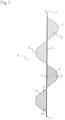
- FIG. 1 shows a first embodiment of occlusion unit 1 of the implant according to the invention in partially expanded view external to a catheter comprising an axial spine 2 , an arch strut 5 with covering 6 , and nylon filaments 7 , 10 ,
- FIG. 2 is a schematic drawing of a first variant of the second embodiment 13 of the occlusion unit comprising four uniformly designed subunits 14 in partially expanded view external to a catheter,
- FIG. 3 is a schematic drawing of the second embodiment 13 of the occlusion unit according to the invention in fully expanded view 18 external to the catheter,
- FIG. 4 is a schematic drawing of a second variant of the second embodiment 13 in partially expanded view external to a catheter, with six subunits 14 ,
- FIG. 5 corresponds to FIG. 4 , with the framework solely being formed by the frame struts 16 .
- FIG. 1 illustrates the first embodiment 1 of the occlusion unit of the implant proposed by the invention in partially expanded, stretched, two-dimensional view situated outside of the catheter, without the final three-dimensional shape being assumed.
- FIG. 2 is a schematic drawing of a first variant of the second embodiment 13 of the implant according to the invention in partially expanded, stretched, two-dimensional view situated outside of the placement catheter, without the final three-dimensional shape being assumed (see FIG. 3 , numeral 18 ).
- the four uniformly designed subunits 14 are formed by struts 16 , 17 , which are provided with a covering 6 .
- the frame of the occlusion unit is formed by two frame struts 16 .
- Two intermediate struts 17 arranged between the frame struts 16 are used for further three-dimensional shaping, said intermediate struts lie side by side in the spaces 15 between the subunits 14 and at the respective proximal 3 and distal 4 ends or are connected to each other.
- FIG. 3 is a schematic drawing of the second embodiment 13 of the implant proposed by the invention in expanded view 18 situated external to the catheter.
- the implant has taken on its final three-dimensional shape.
- the sphere is formed by the frame 16 and intermediate struts 17 and by the covering 6 , which is spanned between them.
- the subunits form individual spherical shell segments that join to form into a ball.
- FIG. 4 illustrates schematically a second variant of the second embodiment 13 of the implant according to the invention in partially expanded, stretched, two-dimensional view situated outside of the catheter, without the final three-dimensional shape (see FIG. 3 , numeral 18 ) being assumed.
- the six subunits 14 of this embodiment are not identical with each other.
- the first proximal and first distal subunits differ from the four subunits arranged in between in that the first proximal subunit has a pointed configuration towards its proximal end and the first distal subunit has a pointed configuration towards its distal end.
- the four subunits arranged in between are identical in shape.
- the subunits are formed by struts 16 , 17 , which have a covering which is not shown in this illustration.
- the frame of the occlusion unit is formed by two frame struts 16 .
- Two intermediate struts 17 arranged between the frame struts 16 are used for further three-dimensional shaping, said intermediate struts lie side by side in the spaces 15 between the subunits 14 and at the respective proximal 3 and distal 4 ends or are connected to each other.
- FIG. 5 corresponds to FIG. 4 , with the framework solely being formed by the frame struts 16 .
Landscapes
- Health & Medical Sciences (AREA)
- Life Sciences & Earth Sciences (AREA)
- Surgery (AREA)
- Animal Behavior & Ethology (AREA)
- Veterinary Medicine (AREA)
- Vascular Medicine (AREA)
- Public Health (AREA)
- General Health & Medical Sciences (AREA)
- Heart & Thoracic Surgery (AREA)
- Engineering & Computer Science (AREA)
- Biomedical Technology (AREA)
- Molecular Biology (AREA)
- Medical Informatics (AREA)
- Nuclear Medicine, Radiotherapy & Molecular Imaging (AREA)
- Reproductive Health (AREA)
- Neurosurgery (AREA)
- Epidemiology (AREA)
- Medicinal Chemistry (AREA)
- Chemical & Material Sciences (AREA)
- Prostheses (AREA)
- Surgical Instruments (AREA)
- Medicinal Preparation (AREA)
- Solid-Sorbent Or Filter-Aiding Compositions (AREA)
- Materials For Medical Uses (AREA)
Abstract
Description
Claims (24)
Applications Claiming Priority (3)
| Application Number | Priority Date | Filing Date | Title |
|---|---|---|---|
| DE102015120554.8A DE102015120554A1 (en) | 2015-11-26 | 2015-11-26 | Belt-shaped occlusion device |
| DE102015120554.8 | 2015-11-26 | ||
| PCT/EP2016/078658 WO2017089451A1 (en) | 2015-11-26 | 2016-11-24 | Band-shaped occlusion means |
Publications (2)
| Publication Number | Publication Date |
|---|---|
| US20180353187A1 US20180353187A1 (en) | 2018-12-13 |
| US11229439B2 true US11229439B2 (en) | 2022-01-25 |
Family
ID=57590474
Family Applications (1)
| Application Number | Title | Priority Date | Filing Date |
|---|---|---|---|
| US15/778,995 Active 2038-04-12 US11229439B2 (en) | 2015-11-26 | 2016-11-24 | Band-shaped occlusion means |
Country Status (12)
| Country | Link |
|---|---|
| US (1) | US11229439B2 (en) |
| EP (1) | EP3380018B1 (en) |
| JP (1) | JP2018537182A (en) |
| KR (1) | KR20180087284A (en) |
| CN (1) | CN108366800A (en) |
| AU (1) | AU2016360868A1 (en) |
| BR (1) | BR112018010670A8 (en) |
| CA (1) | CA3005681A1 (en) |
| DE (1) | DE102015120554A1 (en) |
| ES (1) | ES2967334T3 (en) |
| SG (1) | SG11201804287SA (en) |
| WO (1) | WO2017089451A1 (en) |
Families Citing this family (9)
| Publication number | Priority date | Publication date | Assignee | Title |
|---|---|---|---|---|
| DE102017130564A1 (en) | 2017-12-19 | 2019-06-19 | Phenox Gmbh | Implant for aneurysms |
| DE102018105679A1 (en) | 2018-03-12 | 2019-09-12 | Phenox Gmbh | Temporary occlusion of aneurysmal necks |
| CN113226198B (en) * | 2018-12-26 | 2025-05-13 | 内流医疗有限公司 | Devices for treating vascular malformations |
| DE102019128102A1 (en) * | 2019-10-17 | 2021-04-22 | Phenox Gmbh | Implant for the treatment of aneurysms |
| DE102020118301A1 (en) | 2019-12-23 | 2021-06-24 | Femtos Gmbh | Implant for the treatment of aneurysms |
| WO2022132778A1 (en) * | 2020-12-14 | 2022-06-23 | Julason Richard D | Occluding medical devices and methods of use |
| WO2023034420A1 (en) * | 2021-08-31 | 2023-03-09 | Incumedx Inc. | Embolic device with improved neck coverage |
| CN114081570B (en) * | 2021-12-08 | 2024-03-08 | 杭州拓脉医疗科技有限公司 | Spring ring for embolizing aneurysm and blood vessel |
| DE102023121968A1 (en) | 2023-08-16 | 2025-02-20 | Andratec Gmbh | occluder |
Citations (8)
| Publication number | Priority date | Publication date | Assignee | Title |
|---|---|---|---|---|
| US6428558B1 (en) * | 1999-03-10 | 2002-08-06 | Cordis Corporation | Aneurysm embolization device |
| US6855154B2 (en) * | 2000-08-11 | 2005-02-15 | University Of Louisville Research Foundation, Inc. | Endovascular aneurysm treatment device and method |
| US20060020286A1 (en) * | 2004-07-22 | 2006-01-26 | Volker Niermann | Device for filtering blood in a vessel with helical elements |
| US20090112251A1 (en) * | 2007-07-25 | 2009-04-30 | Aga Medical Corporation | Braided occlusion device having repeating expanded volume segments separated by articulation segments |
| WO2012034135A1 (en) | 2010-09-10 | 2012-03-15 | Maria Aboytes | Devices and methods for the treatment of vascular defects |
| US20150250628A1 (en) * | 2012-08-22 | 2015-09-10 | Phenox Gmbh | Implant |
| US20150305750A1 (en) * | 2014-04-28 | 2015-10-29 | Cook Medical Technologies Llc | Foam occlusion device |
| US20150343181A1 (en) * | 2014-06-02 | 2015-12-03 | Cook Medical Technologies Llc | Occlusion device and methods of using the same |
Family Cites Families (6)
| Publication number | Priority date | Publication date | Assignee | Title |
|---|---|---|---|---|
| US20080147111A1 (en) * | 2005-01-03 | 2008-06-19 | Eric Johnson | Endoluminal Filter With Fixation |
| EP1841488A4 (en) * | 2005-01-03 | 2015-08-05 | Crux Biomedical Inc | Retrievable endoluminal filter |
| DE202008009604U1 (en) * | 2008-07-17 | 2008-11-27 | Sahl, Harald, Dr. | Membrane implant for the treatment of cerebral artery aneurysms |
| US20120245614A1 (en) * | 2011-03-21 | 2012-09-27 | William Joseph Drasler | Branch and Truncal Vessel Occluder |
| US10342548B2 (en) * | 2012-01-13 | 2019-07-09 | W. L. Gore & Associates, Inc. | Occlusion devices and methods of their manufacture and use |
| CN104257412B (en) * | 2014-09-19 | 2017-02-15 | 深圳市人民医院 | Interventional treatment instrument made from composite material and used for treating cerebral aneurysm embolism |
-
2015
- 2015-11-26 DE DE102015120554.8A patent/DE102015120554A1/en not_active Ceased
-
2016
- 2016-11-24 BR BR112018010670A patent/BR112018010670A8/en not_active Application Discontinuation
- 2016-11-24 KR KR1020187016015A patent/KR20180087284A/en not_active Withdrawn
- 2016-11-24 CN CN201680069458.XA patent/CN108366800A/en active Pending
- 2016-11-24 SG SG11201804287SA patent/SG11201804287SA/en unknown
- 2016-11-24 JP JP2018526942A patent/JP2018537182A/en active Pending
- 2016-11-24 US US15/778,995 patent/US11229439B2/en active Active
- 2016-11-24 EP EP16816208.9A patent/EP3380018B1/en active Active
- 2016-11-24 CA CA3005681A patent/CA3005681A1/en not_active Abandoned
- 2016-11-24 WO PCT/EP2016/078658 patent/WO2017089451A1/en not_active Ceased
- 2016-11-24 AU AU2016360868A patent/AU2016360868A1/en not_active Abandoned
- 2016-11-24 ES ES16816208T patent/ES2967334T3/en active Active
Patent Citations (8)
| Publication number | Priority date | Publication date | Assignee | Title |
|---|---|---|---|---|
| US6428558B1 (en) * | 1999-03-10 | 2002-08-06 | Cordis Corporation | Aneurysm embolization device |
| US6855154B2 (en) * | 2000-08-11 | 2005-02-15 | University Of Louisville Research Foundation, Inc. | Endovascular aneurysm treatment device and method |
| US20060020286A1 (en) * | 2004-07-22 | 2006-01-26 | Volker Niermann | Device for filtering blood in a vessel with helical elements |
| US20090112251A1 (en) * | 2007-07-25 | 2009-04-30 | Aga Medical Corporation | Braided occlusion device having repeating expanded volume segments separated by articulation segments |
| WO2012034135A1 (en) | 2010-09-10 | 2012-03-15 | Maria Aboytes | Devices and methods for the treatment of vascular defects |
| US20150250628A1 (en) * | 2012-08-22 | 2015-09-10 | Phenox Gmbh | Implant |
| US20150305750A1 (en) * | 2014-04-28 | 2015-10-29 | Cook Medical Technologies Llc | Foam occlusion device |
| US20150343181A1 (en) * | 2014-06-02 | 2015-12-03 | Cook Medical Technologies Llc | Occlusion device and methods of using the same |
Also Published As
| Publication number | Publication date |
|---|---|
| JP2018537182A (en) | 2018-12-20 |
| CN108366800A (en) | 2018-08-03 |
| BR112018010670A8 (en) | 2019-02-26 |
| KR20180087284A (en) | 2018-08-01 |
| WO2017089451A1 (en) | 2017-06-01 |
| CA3005681A1 (en) | 2017-06-01 |
| EP3380018B1 (en) | 2023-10-11 |
| DE102015120554A1 (en) | 2017-06-01 |
| US20180353187A1 (en) | 2018-12-13 |
| SG11201804287SA (en) | 2018-06-28 |
| AU2016360868A1 (en) | 2018-06-21 |
| ES2967334T3 (en) | 2024-04-29 |
| BR112018010670A2 (en) | 2018-11-13 |
| EP3380018A1 (en) | 2018-10-03 |
Similar Documents
| Publication | Publication Date | Title |
|---|---|---|
| US11229439B2 (en) | Band-shaped occlusion means | |
| US11819217B2 (en) | Embolic devices and methods of manufacturing same | |
| JP6974520B2 (en) | Multi-strand implant with improved radiodensity | |
| EP3672499B1 (en) | Occlusion device | |
| EP3386402B1 (en) | Occlusion device | |
| US9107670B2 (en) | Implant, especially for the occlusion of bifurcation aneurysms | |
| US20110054589A1 (en) | Stent with variable cross section braiding filament and method for making same | |
| ES2908954T3 (en) | Variable porosity intravascular implant and manufacturing method | |
| AU2016374360B2 (en) | Implant | |
| CN106456422A (en) | Devices for treating vascular defects | |
| JP7691044B2 (en) | Multi-layer foldable flow diverter | |
| CN108272481A (en) | A kind of adaptive supporting frame and its manufacturing method | |
| HK40028805A (en) | Occlusion device | |
| HK40028805B (en) | Occlusion device | |
| HK1261731A1 (en) | Occlusion device | |
| HK1261731B (en) | Occlusion device |
Legal Events
| Date | Code | Title | Description |
|---|---|---|---|
| FEPP | Fee payment procedure |
Free format text: ENTITY STATUS SET TO UNDISCOUNTED (ORIGINAL EVENT CODE: BIG.); ENTITY STATUS OF PATENT OWNER: SMALL ENTITY |
|
| FEPP | Fee payment procedure |
Free format text: ENTITY STATUS SET TO SMALL (ORIGINAL EVENT CODE: SMAL); ENTITY STATUS OF PATENT OWNER: SMALL ENTITY |
|
| AS | Assignment |
Owner name: FEMTOS GMBH, GERMANY Free format text: ASSIGNMENT OF ASSIGNORS INTEREST;ASSIGNORS:MONSTADT, HERMANN;HENKES, HANS;HANNES, RALF;SIGNING DATES FROM 20180604 TO 20181005;REEL/FRAME:047924/0540 |
|
| STPP | Information on status: patent application and granting procedure in general |
Free format text: APPLICATION DISPATCHED FROM PREEXAM, NOT YET DOCKETED |
|
| STPP | Information on status: patent application and granting procedure in general |
Free format text: DOCKETED NEW CASE - READY FOR EXAMINATION |
|
| STPP | Information on status: patent application and granting procedure in general |
Free format text: RESPONSE TO NON-FINAL OFFICE ACTION ENTERED AND FORWARDED TO EXAMINER |
|
| STPP | Information on status: patent application and granting procedure in general |
Free format text: FINAL REJECTION MAILED |
|
| STPP | Information on status: patent application and granting procedure in general |
Free format text: ADVISORY ACTION MAILED |
|
| STPP | Information on status: patent application and granting procedure in general |
Free format text: RESPONSE AFTER FINAL ACTION FORWARDED TO EXAMINER |
|
| STPP | Information on status: patent application and granting procedure in general |
Free format text: NOTICE OF ALLOWANCE MAILED -- APPLICATION RECEIVED IN OFFICE OF PUBLICATIONS |
|
| STPP | Information on status: patent application and granting procedure in general |
Free format text: AWAITING TC RESP., ISSUE FEE NOT PAID |
|
| STPP | Information on status: patent application and granting procedure in general |
Free format text: NOTICE OF ALLOWANCE MAILED -- APPLICATION RECEIVED IN OFFICE OF PUBLICATIONS |
|
| STPP | Information on status: patent application and granting procedure in general |
Free format text: PUBLICATIONS -- ISSUE FEE PAYMENT VERIFIED |
|
| STCF | Information on status: patent grant |
Free format text: PATENTED CASE |
|
| FEPP | Fee payment procedure |
Free format text: ENTITY STATUS SET TO UNDISCOUNTED (ORIGINAL EVENT CODE: BIG.); ENTITY STATUS OF PATENT OWNER: LARGE ENTITY |
|
| MAFP | Maintenance fee payment |
Free format text: PAYMENT OF MAINTENANCE FEE, 4TH YEAR, LARGE ENTITY (ORIGINAL EVENT CODE: M1551); ENTITY STATUS OF PATENT OWNER: LARGE ENTITY Year of fee payment: 4 |