US11228219B2 - Winding support and stator - Google Patents
Winding support and stator Download PDFInfo
- Publication number
- US11228219B2 US11228219B2 US16/344,533 US201716344533A US11228219B2 US 11228219 B2 US11228219 B2 US 11228219B2 US 201716344533 A US201716344533 A US 201716344533A US 11228219 B2 US11228219 B2 US 11228219B2
- Authority
- US
- United States
- Prior art keywords
- protrusions
- stator
- winding support
- recited
- winding
- Prior art date
- Legal status (The legal status is an assumption and is not a legal conclusion. Google has not performed a legal analysis and makes no representation as to the accuracy of the status listed.)
- Active
Links
Images


Classifications
-
- H—ELECTRICITY
- H02—GENERATION; CONVERSION OR DISTRIBUTION OF ELECTRIC POWER
- H02K—DYNAMO-ELECTRIC MACHINES
- H02K1/00—Details of the magnetic circuit
- H02K1/06—Details of the magnetic circuit characterised by the shape, form or construction
- H02K1/12—Stationary parts of the magnetic circuit
- H02K1/14—Stator cores with salient poles
- H02K1/146—Stator cores with salient poles consisting of a generally annular yoke with salient poles
-
- H—ELECTRICITY
- H02—GENERATION; CONVERSION OR DISTRIBUTION OF ELECTRIC POWER
- H02K—DYNAMO-ELECTRIC MACHINES
- H02K3/00—Details of windings
- H02K3/32—Windings characterised by the shape, form or construction of the insulation
- H02K3/325—Windings characterised by the shape, form or construction of the insulation for windings on salient poles, such as claw-shaped poles
-
- H—ELECTRICITY
- H02—GENERATION; CONVERSION OR DISTRIBUTION OF ELECTRIC POWER
- H02K—DYNAMO-ELECTRIC MACHINES
- H02K3/00—Details of windings
- H02K3/46—Fastening of windings on the stator or rotor structure
- H02K3/52—Fastening salient pole windings or connections thereto
- H02K3/521—Fastening salient pole windings or connections thereto applicable to stators only
- H02K3/522—Fastening salient pole windings or connections thereto applicable to stators only for generally annular cores with salient poles
-
- H—ELECTRICITY
- H02—GENERATION; CONVERSION OR DISTRIBUTION OF ELECTRIC POWER
- H02K—DYNAMO-ELECTRIC MACHINES
- H02K7/00—Arrangements for handling mechanical energy structurally associated with dynamo-electric machines, e.g. structural association with mechanical driving motors or auxiliary dynamo-electric machines
- H02K7/14—Structural association with mechanical loads, e.g. with hand-held machine tools or fans
- H02K7/145—Hand-held machine tool
-
- B—PERFORMING OPERATIONS; TRANSPORTING
- B25—HAND TOOLS; PORTABLE POWER-DRIVEN TOOLS; MANIPULATORS
- B25F—COMBINATION OR MULTI-PURPOSE TOOLS NOT OTHERWISE PROVIDED FOR; DETAILS OR COMPONENTS OF PORTABLE POWER-DRIVEN TOOLS NOT PARTICULARLY RELATED TO THE OPERATIONS PERFORMED AND NOT OTHERWISE PROVIDED FOR
- B25F5/00—Details or components of portable power-driven tools not particularly related to the operations performed and not otherwise provided for
- B25F5/02—Construction of casings, bodies or handles
Definitions
- the present invention relates to a winding support that serves to at least partially accommodate a stator coil of a stator.
- the winding support has a plurality of protrusions that can each be inserted in an insertion direction into a cavity that is formed by two adjacent stator pole teeth of a laminated core of the stator.
- the present invention likewise relates to a stator for an electric motor, whereby the stator has a laminated core with a plurality of stator pole teeth and two winding supports, whereby each of the winding supports has a plurality of protrusions that are inserted into the laminated core.
- the state of the art discloses, for example, winding supports whose protrusions are connected to each other in the form of a ring and that are made of an electrically insulating plastic in order to electrically insulate the laminated core and the stator coils from each other.
- a stator known from the state of the art typically has two winding supports that are inserted into the laminated core on opposite sides of the laminated core and that together, accommodate a stator coil.
- the winding supports extend into the laminated core only by a relatively short distance, whereby electric insulation is ensured in that an air gap remains between the stator coil and the stator pole tooth.
- the inserted winding supports insulate the laminated core over its entire length, whereby each of the winding supports covers about half the length of the laminated core. In the middle of the laminated core, a gap typically remains in order to compensate for the length tolerance of the laminated core.
- the present invention provides that at least one of the protrusions has a different length in the insertion direction than at least one of the other protrusions.
- the present invention provides that the stator has two winding supports, whereby each of the two winding supports has at least one protrusion that has a different length in the insertion direction than at least one of the other protrusions, whereby the protrusions have to be or are inserted into the cavities in such a way that a longer protrusion of the first winding support and a shorter protrusion of the second winding support are located in the same cavity of the laminated core.
- the invention encompasses the realization that the laminated core of a stator is made up of a plurality of individual laminations (individual lamination thickness typically between 0.35 mm and 0.5 mm) that are held together by stacking points. They have to hold the laminated core together, mainly during the assembly procedure, from the stacking of the stamped cores all the way to the winding procedure. After that, the laminated core is stabilized by the stator winding. If the stacking points are too weak, the laminated core can break apart while it is being transported or being inserted into the winding device. In actual practice, this happens frequently since laminated cores are usually not manufactured at the site of the stator installation, and consequently they sometimes have to be transported over long distances.
- a longer protrusion of the first winding support and a shorter protrusion of the second winding support can be located in the same cavity of the laminated core, as a result of which a continuously circumferential compensation gap can be avoided.
- the winding support has precisely six protrusions. It has proven to be advantageous for the winding support to be made of an electrically insulating plastic.
- the protrusions are connected to each other in the form of a ring.
- two adjacent protrusions each have different lengths. If there is an even number of protrusions, then a short protrusion and a long protrusion can be arranged alternately along the circumference of the winding support. Non-adjacent protrusions are preferably each of the same length.
- At least two, preferably three, adjacent protrusions can have the same length.
- these three adjacent protrusions can form a semi-circle with long protrusions.
- three adjacent protrusions with the same, shorter length can form a semi-circle with short protrusions. It has proven to be advantageous for a longer protrusion to be at least 20% longer than a shorter protrusion.
- the stator has a laminated core and two winding supports as described above.
- the two winding supports are configured to be complementary to each other.
- the first and the second winding supports have to have an identical configuration.
- the first and the second winding supports can exhibit, for example, structural differences in the area of the winding heads and/or structural differences on each of their sides facing away from the laminated core.
- the term “complementary” means that a longer protrusion of the first winding support and a shorter protrusion of the second winding support—when the winding supports have been inserted all the way into the laminated core—complement each other in terms of their length relative to the total length of the laminated core, minus an air gap, which is preferably less than 2 mm.
- winding supports it has proven to be advantageous for the winding supports to be rotated by a given angle relative to each other, whereby this angle is 360 degrees/number of stator pole teeth.
- each surface which is oriented normal to the insertion direction and which is situated within the total length of the laminated core, intersects at least one of the protrusions.
- air gaps that are each equal in size are provided between the protrusions of the first winding support and the corresponding protrusions of the second winding support, relative to the insertion direction.
- the protrusions of the first winding support and the corresponding protrusions of the second winding support to overlap, relative to the insertion direction.
- the thus-defined overlapping area is larger, preferably at least 5 times larger, than the thickness of the individual laminations of the laminated core.
- a preferred thickness of an individual lamination is between 0.35 mm and 0.5 mm.
- the invention likewise encompasses an electric motor that has a stator as described above.
- the invention likewise encompasses a hand-held power tool with such an electric motor.
- FIG. 1 a stator known from the state of the art
- FIG. 2 a second stator known from the state of the art, with stator coils
- FIG. 3 a preferred embodiment of a winding support according to the invention
- FIG. 4A the winding support shown in FIG. 3 , with a complementary (second) winding support;
- FIG. 4B a partial view of two complementary winding supports
- FIG. 5 a stator with the winding supports shown in FIG. 4A , fitted with stator coils;
- FIG. 6 a hand-held power tool with a electric motor and a stator
- FIG. 7 an alternate embodiment of a winding support according to the invention.
- FIG. 1 shows a stator 500 known from the state of the art.
- the stator 500 has a laminated core 400 with six stator pole teeth 10 , 20 , 30 , 40 , 50 , 60 , whereby each of two adjacent teeth form a cavity 12 , 23 , 34 , 45 , 56 , 61 .
- the stator 500 likewise has a first winding support 100 and a second winding support 100 ′.
- the winding supports 100 , 100 ′ have not been inserted into the laminated core 400 .
- the first winding support 100 has six protrusions 1 , 2 , 3 , 4 , 5 , 6 that are each to be inserted in an insertion direction E into the appropriate cavity 12 , 23 , 34 , 45 , 56 , 61 of the laminated core 400 of the stator 500 .
- the second winding support 100 likewise has six protrusions 1 ′, 2 ′, 3 ′, 4 ′, 5 ′, 6 ′ that are each to be inserted in an insertion direction E′ into the appropriate cavity 12 , 23 , 34 , 45 , 56 , 61 of the laminated core 400 of the stator 500 .
- the six protrusions 1 , 2 , 3 , 4 , 5 , 6 of the first winding support 100 and the six protrusions 1 ′, 2 ′, 3 ′, 4 ′, 5 ′, 6 ′ of the second winding support 100 ′ each have identical lengths, relative to their appertaining insertion direction E, E′.
- FIG. 1 shows a structurally minimal solution of the winding supports 100 , 100 ′ in which the protrusions 1 , 2 , 3 , 4 , 5 , 6 ; 1 ′, 2 ′, 3 ′, 4 ′, 5 ′, 6 ′ extend into the laminated core 400 only by a relatively short distance, that is to say, essentially in the area of a winding head K, K′ at the beginning and at the end of the laminated core 400 .
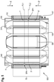
- FIG. 2 shows another stator 500 known from the state of the art. For the sake of clarity, a sectional view was selected in which three (of six) stator coils 310 , 320 , 330 can be seen.
- the laminated core 400 is identical to the laminated core 400 shown in FIG. 1 .
- the winding supports 100 , 100 ′ inserted into the laminated core 400 insulate the laminated core 400 over the entire length of the laminated core GL, whereby each of the winding supports 100 , 100 ′ covers about half the length of the laminated core GL.
- a gap SP remains in the middle of the laminated core 400 in order to compensate for the length tolerance of the laminated core 400 .
- the continuously circumferential compensation gap SP that remains between the winding supports 100 , 100 ′ forms an undesired rupture point.
- FIG. 3 shows a preferred embodiment of a winding support 100 according to the invention.
- the winding support 100 is configured to at least partially accommodate a stator coil 300 , 320 , 330 (see FIG. 5 ) of a stator 500 .
- the winding support 100 has precisely six protrusions 1 , 2 , 3 , 4 , 5 , 6 .
- the protrusions 1 , 2 , 3 , 4 , 5 , 6 are each to be inserted in an insertion direction E into a cavity 12 , 23 , 34 , 45 , 56 , 61 (see FIG. 1 ) that is formed by two adjacent stator pole teeth 60 , 10 ; 10 , 20 ; 20 , 30 ; 30 , 40 ; 40 , 50 ; 50 , 60 of a laminated core 400 of a stator 500 (see FIG. 1 ).
- precisely three of the protrusions 1 , 3 , 5 in the insertion direction E have different, namely, greater lengths than the remaining other protrusions 2 , 4 , 6 .
- two immediately adjacent protrusions 1 , 2 ; 2 , 3 ; 3 , 4 ; 4 , 5 ; 5 , 6 ; 6 , 1 each have different lengths.
- a short protrusion 2 , 4 , 6 and a long protrusion 1 , 3 , 5 are distributed alternately along the circumference U of the winding support 100 .
- the winding support 100 is made of an electrically insulating plastic and the protrusions 1 , 2 , 3 , 4 , 5 , 6 are connected to each other in the form of a ring, in the present embodiment, by means of an appertaining connecting ring 110 .
- FIG. 4A shows the winding support 100 of FIG. 3 , with a complementary second winding support 100 ′ (at the bottom in FIG. 4A ).
- the first winding support 100 and the second winding support 100 ′ have an identical configuration as far as the protrusions 1 , 2 , 3 , 4 , 5 , 6 ; 1 ′, 2 ′, 3 ′, 4 ′, 5 ′, 6 ′ are concerned.
- the winding supports 100 , 100 ′ are rotated by a given angle W relative to each other, whereby the angle is 60 degrees, since the winding supports 100 , 100 ′ are configured for a laminated core with precisely six stator pole teeth 10 , 20 , 30 , 40 , 50 , 60 (see FIG. 1 ).
- first and second winding supports 100 , 100 ′ have structural differences in the area of the winding heads K, K′ and structural differences on each of their sides of the connecting rings 110 , 110 ′ facing away from the laminated core (not shown here).
- FIG. 4B shows a partial view of two complementary winding supports 100 , 100 ′.
- the long protrusions 1 , 1 ′ have a length LL of 15 mm while the short protrusions 2 , 6 ′ have a length KL of 11 mm.
- the air gaps SP 1 , SP 2 are each 1 mm long.
- the protrusions 1 , 2 of the first winding support 100 and the corresponding protrusions 6 ′, 1 ′ of the second winding support 100 ′ overlap, relative to the insertion direction E, E′, in an overlapping area UB, that is thus, for instance, 3 mm wide by way of example.
- the overlapping area UB is also at least 5 times greater than the thickness of the individual laminations EB of the laminated core 400 , which is, for instance, 0.35 mm.
- FIG. 5 shows a stator 500 with a laminated core 400 into which the winding supports 100 , 100 ′ of FIG. 4A have been properly inserted.
- a sectional view was selected in which two (of six) stator coils 310 , 340 can be seen.
- the laminated core 400 is identical to the laminated core 400 shown in FIG. 1 .
- a first surface FL 1 runs without intersections through a first air gap SP 1 that is situated between two corresponding protrusions 1 , 6 ′.
- this first surface that intersects another protrusion 4 of the first winding support 100 .
- each surface here, for instance, the surfaces FL 1 , FL 2 —that is oriented normal to the insertion direction E and that is situated within the total length GL of the laminated core, intersects at least one of the protrusions 1 , 3 ′.
- FIG. 6 shows a hand-held power tool 2000 with an electric motor 1000 into which—schematically depicted—a stator 500 according to the invention has been installed.
- FIG. 7 An alternative embodiment is shown solely schematically in FIG. 7 in which three adjacent protrusions can have the same length.
- Precisely six protrusions 101 , 102 , 103 , 104 , 105 , 106 are provided, whereby three adjacent protrusions 101 , 102 , 103 have the same length, then these three adjacent protrusions can form a semi-circle with long protrusions.
- three adjacent protrusions 104 , 105 , 106 with the same, shorter length can form a semi-circle with short protrusions.
Landscapes
- Engineering & Computer Science (AREA)
- Power Engineering (AREA)
- Iron Core Of Rotating Electric Machines (AREA)
- Insulation, Fastening Of Motor, Generator Windings (AREA)
Abstract
Description
- 100, 100′ first, second winding support
- 110, 110′ connecting ring
- 1, 2, 3, 4, 5, 6 protrusions of the first winding support
- 1′, 2′, 3′, 4′, 5′ 6′ protrusions of the second winding support
- 10, 20, 30, 40, 50, 60 stator pole teeth
- 12, 23, 34, 45, 56, 61 cavity
- 101, 102, 103, 104, 105, 106 protrusions of an alternate embodiment
- 300, 310, 320, 330, 340 stator coil
- 400 laminated core
- 500 stator
- 1000 electric motor
- 2000 hand-held power tool
- E, E′ insertion direction
- EB thickness of the individual laminations
- FL0, FL1, FL2 surfaces
- GL total length of the laminated core
- K, K′ winding head
- SP, SP1, SP2, SP4 air gap
- U circumference
- UB overlapping area
- W angle
Claims (19)
Applications Claiming Priority (4)
| Application Number | Priority Date | Filing Date | Title |
|---|---|---|---|
| EP16195417.7 | 2016-10-25 | ||
| EP16195417.7A EP3316454A1 (en) | 2016-10-25 | 2016-10-25 | Roll support and stator |
| EP16195417 | 2016-10-25 | ||
| PCT/EP2017/076007 WO2018077625A1 (en) | 2016-10-25 | 2017-10-12 | Winding support and stator |
Publications (2)
| Publication Number | Publication Date |
|---|---|
| US20190288575A1 US20190288575A1 (en) | 2019-09-19 |
| US11228219B2 true US11228219B2 (en) | 2022-01-18 |
Family
ID=57189963
Family Applications (1)
| Application Number | Title | Priority Date | Filing Date |
|---|---|---|---|
| US16/344,533 Active US11228219B2 (en) | 2016-10-25 | 2017-10-12 | Winding support and stator |
Country Status (4)
| Country | Link |
|---|---|
| US (1) | US11228219B2 (en) |
| EP (2) | EP3316454A1 (en) |
| CN (1) | CN109891715B (en) |
| WO (1) | WO2018077625A1 (en) |
Families Citing this family (5)
| Publication number | Priority date | Publication date | Assignee | Title |
|---|---|---|---|---|
| KR102294928B1 (en) | 2015-01-06 | 2021-08-31 | 엘지이노텍 주식회사 | Stator and motor using the same |
| CN110401287A (en) * | 2019-07-09 | 2019-11-01 | 珠海格力节能环保制冷技术研究中心有限公司 | An insulating skeleton, a stator and a motor |
| EP3829041A1 (en) | 2019-11-29 | 2021-06-02 | Hilti Aktiengesellschaft | Hall board within winding heads |
| EP3829039A1 (en) | 2019-11-29 | 2021-06-02 | Hilti Aktiengesellschaft | Hall pcb with bearing passage opening |
| EP3832854A1 (en) | 2019-12-06 | 2021-06-09 | Hilti Aktiengesellschaft | Internal calibration bearing seat and hall pcb in stator |
Citations (18)
| Publication number | Priority date | Publication date | Assignee | Title |
|---|---|---|---|---|
| US4028573A (en) * | 1975-04-29 | 1977-06-07 | Societe Anonyme Des Equipements S.E.I.M. | Rotor for an electrical machine |
| US20020047457A1 (en) * | 2000-03-31 | 2002-04-25 | Shouichi Yoshikawa | Rotary electric machine and manufacturing method therefor |
| US20040245882A1 (en) * | 2001-09-03 | 2004-12-09 | Tatsuro Horie | Rotary electric machine stator |
| US20060091757A1 (en) | 2004-11-04 | 2006-05-04 | Minebea Co., Ltd. | Slot insulator and multiplexed resolver using same |
| US7242125B2 (en) * | 2004-07-13 | 2007-07-10 | Minebea Co., Ltd. | Device for the insulation of stator slots |
| WO2009019562A2 (en) * | 2007-08-07 | 2009-02-12 | Spal Automotive S.R.L. | Electric machine |
| CN201307796Y (en) | 2009-03-18 | 2009-09-09 | 常州富兴机电有限公司 | Insulation skeleton of a motor coil |
| JP2012095488A (en) * | 2010-10-28 | 2012-05-17 | Toyota Motor Corp | Rotor for rotary electric machine and rotary electric machine using the same |
| WO2012090424A1 (en) * | 2010-12-29 | 2012-07-05 | Nidec Corporation | Armature and motor including armature |
| US20130043743A1 (en) * | 2011-08-16 | 2013-02-21 | Lg Innotek Co., Ltd. | Stator of Motor |
| US20130062972A1 (en) * | 2011-09-09 | 2013-03-14 | Aisin Seiki Kabushiki Kaisha | Three-phase rotary electrical machine and manufacturing method thereof |
| US20130193800A1 (en) * | 2012-01-31 | 2013-08-01 | Nidec Corporation | Armature and motor |
| JP2013247763A (en) | 2012-05-25 | 2013-12-09 | Panasonic Corp | Motor and ceiling fan mounted therewith |
| US20140203671A1 (en) * | 2013-01-18 | 2014-07-24 | Hyunho Ha | Motor |
| US20150338243A1 (en) * | 2014-05-21 | 2015-11-26 | Minebea Co., Ltd. | Resolver |
| US20160028285A1 (en) * | 2014-07-25 | 2016-01-28 | Aisin Seiki Kabushiki Kaisha | Rotating electrical machine |
| US9461515B2 (en) * | 2013-07-02 | 2016-10-04 | Nidec Corporation | Motor having wiring arrangement with respect to stator insulation and circuit |
| JP2017192238A (en) * | 2016-04-14 | 2017-10-19 | ファナック株式会社 | Electric motor insulation parts |
-
2016
- 2016-10-25 EP EP16195417.7A patent/EP3316454A1/en not_active Withdrawn
-
2017
- 2017-10-12 CN CN201780062300.4A patent/CN109891715B/en active Active
- 2017-10-12 WO PCT/EP2017/076007 patent/WO2018077625A1/en not_active Ceased
- 2017-10-12 EP EP17788176.0A patent/EP3533132B1/en active Active
- 2017-10-12 US US16/344,533 patent/US11228219B2/en active Active
Patent Citations (21)
| Publication number | Priority date | Publication date | Assignee | Title |
|---|---|---|---|---|
| US4028573A (en) * | 1975-04-29 | 1977-06-07 | Societe Anonyme Des Equipements S.E.I.M. | Rotor for an electrical machine |
| US20020047457A1 (en) * | 2000-03-31 | 2002-04-25 | Shouichi Yoshikawa | Rotary electric machine and manufacturing method therefor |
| US20040245882A1 (en) * | 2001-09-03 | 2004-12-09 | Tatsuro Horie | Rotary electric machine stator |
| US7242125B2 (en) * | 2004-07-13 | 2007-07-10 | Minebea Co., Ltd. | Device for the insulation of stator slots |
| US20060091757A1 (en) | 2004-11-04 | 2006-05-04 | Minebea Co., Ltd. | Slot insulator and multiplexed resolver using same |
| WO2009019562A2 (en) * | 2007-08-07 | 2009-02-12 | Spal Automotive S.R.L. | Electric machine |
| US20100171380A1 (en) * | 2007-08-07 | 2010-07-08 | Spal Automotive S.R.L | Electric machine |
| CN201307796Y (en) | 2009-03-18 | 2009-09-09 | 常州富兴机电有限公司 | Insulation skeleton of a motor coil |
| JP2012095488A (en) * | 2010-10-28 | 2012-05-17 | Toyota Motor Corp | Rotor for rotary electric machine and rotary electric machine using the same |
| US20130221770A1 (en) * | 2010-12-29 | 2013-08-29 | Nidec Corporation | Armature and motor including armature |
| WO2012090424A1 (en) * | 2010-12-29 | 2012-07-05 | Nidec Corporation | Armature and motor including armature |
| US20130043743A1 (en) * | 2011-08-16 | 2013-02-21 | Lg Innotek Co., Ltd. | Stator of Motor |
| US20130062972A1 (en) * | 2011-09-09 | 2013-03-14 | Aisin Seiki Kabushiki Kaisha | Three-phase rotary electrical machine and manufacturing method thereof |
| US8853910B2 (en) * | 2011-09-09 | 2014-10-07 | Aisin Seiki Kabushiki Kaisha | Three-phase rotary electrical machine and manufacturing method thereof |
| US20130193800A1 (en) * | 2012-01-31 | 2013-08-01 | Nidec Corporation | Armature and motor |
| JP2013247763A (en) | 2012-05-25 | 2013-12-09 | Panasonic Corp | Motor and ceiling fan mounted therewith |
| US20140203671A1 (en) * | 2013-01-18 | 2014-07-24 | Hyunho Ha | Motor |
| US9461515B2 (en) * | 2013-07-02 | 2016-10-04 | Nidec Corporation | Motor having wiring arrangement with respect to stator insulation and circuit |
| US20150338243A1 (en) * | 2014-05-21 | 2015-11-26 | Minebea Co., Ltd. | Resolver |
| US20160028285A1 (en) * | 2014-07-25 | 2016-01-28 | Aisin Seiki Kabushiki Kaisha | Rotating electrical machine |
| JP2017192238A (en) * | 2016-04-14 | 2017-10-19 | ファナック株式会社 | Electric motor insulation parts |
Also Published As
| Publication number | Publication date |
|---|---|
| US20190288575A1 (en) | 2019-09-19 |
| WO2018077625A1 (en) | 2018-05-03 |
| CN109891715A (en) | 2019-06-14 |
| CN109891715B (en) | 2021-12-31 |
| EP3533132B1 (en) | 2020-05-13 |
| EP3533132A1 (en) | 2019-09-04 |
| EP3316454A1 (en) | 2018-05-02 |
Similar Documents
| Publication | Publication Date | Title |
|---|---|---|
| US11228219B2 (en) | Winding support and stator | |
| US8278803B2 (en) | Motor end cap positioning element for maintaining rotor-stator concentricity | |
| US8018115B2 (en) | Alignment of segmented stators for electric machines | |
| US9059611B2 (en) | Stator core | |
| MX2016005933A (en) | Single-phase outer-rotor motor and stator thereof. | |
| CN104184226B (en) | Motor and possesses the compressor of the motor | |
| JP2013046420A (en) | Winding coil and stator core with winding coil | |
| EP3166206B1 (en) | Electric motor | |
| EP3010118A2 (en) | Stator of rotary electric machine | |
| US11336133B2 (en) | Stator for an electric motor | |
| US10424979B2 (en) | Stator for an electric motor having respective angled slots | |
| KR20170035794A (en) | Single phase permanent magnet motor | |
| JP2004260985A (en) | Armature of rotary electric machine, rotary electric machine using the same, and method of manufacturing armature of rotary electric machine | |
| US1028985A (en) | Dynamo-electric machine. | |
| JP2016082839A (en) | Brushless motor | |
| US10454332B2 (en) | Active part of an electric machine | |
| US10581290B2 (en) | Reluctance armature | |
| JP5466117B2 (en) | Method for manufacturing stator of electric motor and method for positioning stator coil | |
| JP2015162975A (en) | Stator and inner rotor type motor | |
| JP6293382B1 (en) | Stator core piece and rotating electric machine | |
| JP2017169310A (en) | Stator | |
| KR20110118244A (en) | Stator for motor and motor with same | |
| WO2015162644A1 (en) | Stator of dynamo-electric machine, dynamo-electric machine in which said stator is used, and method for inserting coil onto stator of dynamo-electric machine | |
| JP2005027492A (en) | Permanent magnet motor | |
| JP2019016139A (en) | Haptic device |
Legal Events
| Date | Code | Title | Description |
|---|---|---|---|
| FEPP | Fee payment procedure |
Free format text: ENTITY STATUS SET TO UNDISCOUNTED (ORIGINAL EVENT CODE: BIG.); ENTITY STATUS OF PATENT OWNER: LARGE ENTITY |
|
| AS | Assignment |
Owner name: HILTI AKTIENGESELLSCHAFT, LIECHTENSTEIN Free format text: ASSIGNMENT OF ASSIGNORS INTEREST;ASSIGNORS:TUSSING, TORSTEN;BURGER, HELMUT;LUDWIG, WOLFGANG;SIGNING DATES FROM 20190123 TO 20190124;REEL/FRAME:049017/0712 |
|
| STPP | Information on status: patent application and granting procedure in general |
Free format text: DOCKETED NEW CASE - READY FOR EXAMINATION |
|
| STPP | Information on status: patent application and granting procedure in general |
Free format text: NON FINAL ACTION MAILED |
|
| STCV | Information on status: appeal procedure |
Free format text: NOTICE OF APPEAL FILED |
|
| STCV | Information on status: appeal procedure |
Free format text: APPEAL BRIEF (OR SUPPLEMENTAL BRIEF) ENTERED AND FORWARDED TO EXAMINER |
|
| STPP | Information on status: patent application and granting procedure in general |
Free format text: FINAL REJECTION MAILED |
|
| STPP | Information on status: patent application and granting procedure in general |
Free format text: RESPONSE AFTER FINAL ACTION FORWARDED TO EXAMINER |
|
| STPP | Information on status: patent application and granting procedure in general |
Free format text: NOTICE OF ALLOWANCE MAILED -- APPLICATION RECEIVED IN OFFICE OF PUBLICATIONS |
|
| STPP | Information on status: patent application and granting procedure in general |
Free format text: PUBLICATIONS -- ISSUE FEE PAYMENT VERIFIED |
|
| STCF | Information on status: patent grant |
Free format text: PATENTED CASE |
|
| MAFP | Maintenance fee payment |
Free format text: PAYMENT OF MAINTENANCE FEE, 4TH YEAR, LARGE ENTITY (ORIGINAL EVENT CODE: M1551); ENTITY STATUS OF PATENT OWNER: LARGE ENTITY Year of fee payment: 4 |