US11226607B2 - Abnormality determination system, data transmitter-receptor, motor controller, and method for determining abnormality - Google Patents
Abnormality determination system, data transmitter-receptor, motor controller, and method for determining abnormality Download PDFInfo
- Publication number
- US11226607B2 US11226607B2 US15/948,164 US201815948164A US11226607B2 US 11226607 B2 US11226607 B2 US 11226607B2 US 201815948164 A US201815948164 A US 201815948164A US 11226607 B2 US11226607 B2 US 11226607B2
- Authority
- US
- United States
- Prior art keywords
- data
- motor
- abnormality
- operation data
- driven machine
- Prior art date
- Legal status (The legal status is an assumption and is not a legal conclusion. Google has not performed a legal analysis and makes no representation as to the accuracy of the status listed.)
- Active, expires
Links
Images


Classifications
-
- G—PHYSICS
- G05—CONTROLLING; REGULATING
- G05B—CONTROL OR REGULATING SYSTEMS IN GENERAL; FUNCTIONAL ELEMENTS OF SUCH SYSTEMS; MONITORING OR TESTING ARRANGEMENTS FOR SUCH SYSTEMS OR ELEMENTS
- G05B19/00—Program-control systems
- G05B19/02—Program-control systems electric
- G05B19/04—Program control other than numerical control, i.e. in sequence controllers or logic controllers
- G05B19/05—Programmable logic controllers, e.g. simulating logic interconnections of signals according to ladder diagrams or function charts
- G05B19/058—Safety, monitoring
-
- G—PHYSICS
- G05—CONTROLLING; REGULATING
- G05B—CONTROL OR REGULATING SYSTEMS IN GENERAL; FUNCTIONAL ELEMENTS OF SUCH SYSTEMS; MONITORING OR TESTING ARRANGEMENTS FOR SUCH SYSTEMS OR ELEMENTS
- G05B23/00—Testing or monitoring of control systems or parts thereof
- G05B23/02—Electric testing or monitoring
- G05B23/0205—Electric testing or monitoring by means of a monitoring system capable of detecting and responding to faults
- G05B23/0218—Electric testing or monitoring by means of a monitoring system capable of detecting and responding to faults characterised by the fault detection method dealing with either existing or incipient faults
- G05B23/0224—Process history based detection method, e.g. whereby history implies the availability of large amounts of data
- G05B23/024—Quantitative history assessment, e.g. mathematical relationships between available data; Functions therefor; Principal component analysis [PCA]; Partial least square [PLS]; Statistical classifiers, e.g. Bayesian networks, linear regression or correlation analysis; Neural networks
-
- G—PHYSICS
- G05—CONTROLLING; REGULATING
- G05B—CONTROL OR REGULATING SYSTEMS IN GENERAL; FUNCTIONAL ELEMENTS OF SUCH SYSTEMS; MONITORING OR TESTING ARRANGEMENTS FOR SUCH SYSTEMS OR ELEMENTS
- G05B23/00—Testing or monitoring of control systems or parts thereof
- G05B23/02—Electric testing or monitoring
- G05B23/0205—Electric testing or monitoring by means of a monitoring system capable of detecting and responding to faults
- G05B23/0218—Electric testing or monitoring by means of a monitoring system capable of detecting and responding to faults characterised by the fault detection method dealing with either existing or incipient faults
- G05B23/0221—Preprocessing measurements, e.g. data collection rate adjustment; Standardization of measurements; Time series or signal analysis, e.g. frequency analysis or wavelets; Trustworthiness of measurements; Indexes therefor; Measurements using easily measured parameters to estimate parameters difficult to measure; Virtual sensor creation; De-noising; Sensor fusion; Unconventional preprocessing inherently present in specific fault detection methods like PCA-based methods
-
- G—PHYSICS
- G05—CONTROLLING; REGULATING
- G05B—CONTROL OR REGULATING SYSTEMS IN GENERAL; FUNCTIONAL ELEMENTS OF SUCH SYSTEMS; MONITORING OR TESTING ARRANGEMENTS FOR SUCH SYSTEMS OR ELEMENTS
- G05B23/00—Testing or monitoring of control systems or parts thereof
- G05B23/02—Electric testing or monitoring
- G05B23/0205—Electric testing or monitoring by means of a monitoring system capable of detecting and responding to faults
- G05B23/0218—Electric testing or monitoring by means of a monitoring system capable of detecting and responding to faults characterised by the fault detection method dealing with either existing or incipient faults
- G05B23/0224—Process history based detection method, e.g. whereby history implies the availability of large amounts of data
- G05B23/0227—Qualitative history assessment, whereby the type of data acted upon, e.g. waveforms, images or patterns, is not relevant, e.g. rule based assessment; if-then decisions
- G05B23/0232—Qualitative history assessment, whereby the type of data acted upon, e.g. waveforms, images or patterns, is not relevant, e.g. rule based assessment; if-then decisions based on qualitative trend analysis, e.g. system evolution
-
- G—PHYSICS
- G05—CONTROLLING; REGULATING
- G05B—CONTROL OR REGULATING SYSTEMS IN GENERAL; FUNCTIONAL ELEMENTS OF SUCH SYSTEMS; MONITORING OR TESTING ARRANGEMENTS FOR SUCH SYSTEMS OR ELEMENTS
- G05B2219/00—Program-control systems
- G05B2219/10—Plc systems
- G05B2219/11—Plc I-O input output
- G05B2219/1134—Fieldbus
-
- G—PHYSICS
- G05—CONTROLLING; REGULATING
- G05B—CONTROL OR REGULATING SYSTEMS IN GENERAL; FUNCTIONAL ELEMENTS OF SUCH SYSTEMS; MONITORING OR TESTING ARRANGEMENTS FOR SUCH SYSTEMS OR ELEMENTS
- G05B2219/00—Program-control systems
- G05B2219/10—Plc systems
- G05B2219/12—Plc mp multi processor system
- G05B2219/1214—Real-time communication between plc, Ethernet for configuration, monitor
Definitions
- the embodiments disclosed herein relate to an abnormality determination system, a data transmitter-receptor, a motor controller, and a method for determining an abnormality.
- JP 5480440B discloses an abnormality sign detector that obtains time-series data from a plurality of apparatuses and/or devices included in machinery or equipment and that determines whether there is an abnormality sign based on the time-series data.
- an abnormality determination system includes motor control circuitry that controls a motor of a motor-driven machine based on a motor control command, and compares operation data of the motor obtained in controlling the motor with reference data stored in a storage to determine whether the motor driven machine has an operation abnormality, upper-level control circuitry that transmits the motor control command to the motor control circuitry, and data transceiver circuitry that transmits and receives the reference data and the operation data to and from the motor control circuitry.
- an apparatus includes data transmitter-receptor that receives reference data from data management circuitry, transmits the received reference data to motor control circuitry, receives operation data from the motor control circuitry, and transmits the received operation data to the data management circuitry.
- an apparatus includes motor control circuitry that controls a motor of a motor-driven machine and determines whether the motor-driven machine has an operation abnormality by comparing observation-time operation data of the motor with reference data.
- the observation-time operation data is obtained while the motor-driven machine is being driven for observation purposes, the reference data is calculated based on normal operation data of the motor obtained while the motor driven machine is being driven normally.
- a method for determining an abnormality in a motor-driven machine includes obtaining observation-time operation data of a motor of the motor-driven machine, the observation-time operation data being operation data obtained while the motor driven machine is being driven for observation purposes, determining whether the observation-time operation data has a data abnormality using reference data generated by machine learning, and determining whether the motor driven machine has an operation abnormality based on an acquisition situation in which the observation-time operation data, determined as having the data abnormality, was obtained.
- FIG. 1 is a schematic illustrating a system configuration of an abnormality determination system according to an embodiment
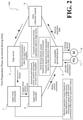
- FIG. 2 illustrates details of processings performed by system components of the abnormality determination system in a first preparation phase, which is performed at the time of normal driving, and illustrates flows of information exchanged between the system components in the first preparation phase;
- FIG. 3 illustrates details of processings performed by the system components in a second preparation phase, and illustrates flows of information exchanged between the system components in the second preparation phase;
- FIG. 4 illustrates details of processings performed by the system components in an operational phase, which is performed at the time of observation driving, and illustrates flows of information exchanged between the system components in the operational phase;
- FIG. 5 illustrates exemplary normal operation data and exemplary reference data
- FIG. 6 illustrates a comparison between reference data and observation-time operation data of a torque command
- FIG. 7 illustrates a relationship between chi-squared distribution, data abnormality determination threshold, and Mahalanobis distance
- FIG. 8 illustrates an example of how a data abnormality is detected from observation-time operation data in determination as to whether there is an operation abnormality caused by aging degradation
- FIG. 9 is a flowchart of abnormality determination processing, which includes data abnormality determination and operation abnormality determination;
- FIG. 10 illustrates a system configuration in which a data collection module is integral to an edge server
- FIG. 11 illustrates a system configuration in which the data collection module is integral to a servo amplifier
- FIG. 12 illustrates a system configuration in which the data collection module is integral to the servo amplifier and transmits and receives data to and from the edge server through a wireless communication.
- FIG. 1 a general arrangement of an abnormality determination system 100 according to this embodiment will be described.
- FIG. 1 is a schematic illustrating a system configuration of an abnormality determination system 100 .
- the abnormality determination system 100 is a system that controls driving of machine systems, such as manufacturing machines, disposed in factories, plants, and other industrial facilities.
- the abnormality determination system 100 also obtains operation data of the machine systems and detects an operation abnormality in the machine systems.
- the abnormality determination system 100 includes a motor driven machine 1 , servo amplifiers 2 , an upper-level controller 3 , an edge server 4 , a data collection module 5 , and an upper-level commander 7 .
- the motor driven machine 1 is a target machine system in which the abnormality determination system 100 determines whether there are various kinds of driving-related abnormality.
- the motor driven machine 1 includes a plurality of motors 12 (four motors 12 in the embodiment illustrated in FIG. 1 ) and driven mechanisms (not illustrated) driven by the respective motors 12 .
- Each of the motors 12 includes an encoder 11 .
- the motor driven machine 1 is a multi-axis machine system. Specifically, the motors 12 are controlled at different operation patterns into coordination as a whole.
- each motor 12 is a rotary electric motor
- the encoder 11 is a sensor that optically detects the rotation angle of the motor 12 and outputs the detected rotation angle.
- the motor 12 will not be limited to a rotary motor but may be a “linear motor”, which makes linear motion.
- the linear motor includes an angle detection sensor, instead of the encoder 11 .
- a non-limiting example of the angle detection sensor is a linear scale (not illustrated).
- the motor driven machine 1 also includes external sensors 13 (each simply termed “sensor” in FIG. 1 ).
- the external sensors 13 are capable of detecting various state quantities associated with the driving control of the motors 12 . Examples of the state quantities include, but are not limited to, vibration, instrument temperature, environment temperature, and environment humidity of the motors 12 and the motor driven machine 1 .
- Each external sensor 13 is connected to a corresponding encoder 11 through a “field network”, such as ⁇ -LINK (registered trademark), so that information can be transmitted and received between the external sensor 13 and the encoder 11 .
- a field network such as ⁇ -LINK (registered trademark)
- ⁇ -LINK registered trademark
- the servo amplifiers 2 correspond to the respective motors 12 , and generate driving electric power based on a motor control command input from the upper-level controller 3 (upper-level controller), described later. Each servo amplifier 2 feeds the generated driving electric power to the corresponding motor 12 to control driving of the motor 12 .
- each servo amplifier 2 obtains, in some order, two kinds of time-series data as operation data and transmits the operation data to an external instrument (see FIGS. 2 and 4 , described later).
- the operation data are a torque command and an output speed.
- the torque command is generated while the driving electric power is being fed to the motor 12 .
- the output speed is generated based on the angle of the motor 12 output from the encoder 11 .
- each servo amplifier 2 also compares the obtained operation data with reference data stored in advance in a storage so as to determine whether the motor driven machine 1 has an operation abnormality. This function of detecting an operation abnormality will be detailed later.
- the upper-level controller 3 controls the motor driven machine 1 to perform a desired time-dependent driving operation by successively generating and outputting motor control commands for the motors 12 , such as output angle commands. These functions of the upper-level controller 3 to generate and output the motor control commands are based on upper-level control commands input from the upper-level commander 7 , described later. Specifically, the timings of starting and stopping the motor control commands and parameters for the motor control commands are set based on the upper-level control commands.
- the upper-level controller 3 is connected to the servo amplifiers 2 through a “field network” dedicated to signal communication between machine control-purpose system components so that information can be transmitted and received between the upper-level controller 3 and the servo amplifiers 2 .
- a field network dedicated to signal communication between machine control-purpose system components so that information can be transmitted and received between the upper-level controller 3 and the servo amplifiers 2 .
- MECHATROLINK registered trademark
- the edge server 4 (data manager) is implemented by, for example, a desktop general-purpose personal computer to manage and control the abnormality determination system 100 as a whole based on an input operation (access) by a user.
- the edge server 4 is connected to the data collection module 5 , described later, through ETHERNET (registered trademark) so that the edge server 4 obtains operation data from the servo amplifiers 2 and stores and manages the operation data.
- the edge server 4 uses normal driving-time operation data, described later, as a basis for generating reference data used for detecting a data abnormality. The processing of generating the reference data will be detailed later. Also as illustrated in FIG.
- the edge server 4 is connected to an external cloud server 6 through a wide-area network NW, such as the Internet, so that information can be transmitted and received between the edge server 4 and the cloud server 6 .
- NW wide-area network
- the edge server 4 may be disconnected from the cloud server 6 in security-valued network applications.
- the data collection module 5 (data transmitter-receptor) serves as a relay through which information such as various kinds of data and notification information are transmitted and received between the edge server 4 and the servo amplifiers 2 .
- the data collection module 5 is one of the terminals, including the servo amplifiers 2 , that are connected to the above-described field network MECHATROLINK. This configuration enables the data collection module 5 to transmit and receive various kinds of data to and from the servo amplifiers 2 in a parallel, real-time manner.
- the data collection module 5 is also connected to the edge server 4 through the ETHERNET. This configuration enables the data collection module 5 to transmit and receive various kinds of data to and from the edge server 4 at high speed.
- the data collection module 5 accommodates to differences in communications standards and processing cycle between the edge server 4 and the servo amplifiers 2 , making a smooth relay of various kinds of data between the edge server 4 and the servo amplifiers 2 .
- One difference in communications standards is data transmission characteristics; a typical field network (which is the side of the servo amplifiers 2 ) is short in access period and narrow in transmission bandwidth, whereas the ETHERNET (registered trademark) (which is the side of the edge server 4 ) is long in access period and wide in transmission bandwidth.
- the data collection module 5 appropriately performs data buffering and synchronization control of data transmission and reception so that a large amount of data is smoothly transmitted and received between the different communications standards.
- the upper-level commander 7 is made up of a general-purpose personal computer, a Programmable Logic Controller (PLC), and other elements. With this configuration, the upper-level commander 7 controls the motor driven machine 1 as a whole to be activated and stopped. Specifically, the upper-level commander 7 refers to operation data, abnormality determination results, and other information stored in the edge server 4 so as to monitor the operation status of the motor driven machine 1 . Based on the operation status, the upper-level commander 7 generates an upper-level control command, and transmits the upper-level control command to the upper-level controller 3 . The upper-level control command causes the upper-level controller 3 to start and stop generating and outputting a motor control command (so as to activate or stop the motor driven machine 1 as a whole), or causes the upper-level controller 3 to set various parameters for the motor control command.
- PLC Programmable Logic Controller
- an upper-level controller In a typical system for controlling driving of a motor driven machine, an upper-level controller generates and transmits a motor control command to a servo amplifier, and the servo amplifier controls the motor of the motor driven machine based on the motor control command.
- This configuration ensures sequence control of the motor driven machine in an operation pattern that combines a wide variety of motor control commands in a time-series manner.
- a single upper-level controller When there are a plurality of motors to drive the motor driven machine, a single upper-level controller generates and transmits a motor control command to each of servo amplifiers corresponding to the respective motors. This configuration ensures sequence control of the motor driven machine 1 as a whole with the motors driven in coordination.
- the CPU of the upper-level controller has limited processing resources (throughput), which makes it difficult for the single upper-level controller to perform the additional processings of determining whether each of the plurality of motors has a driving operation abnormality and successively obtaining and storing sensor data, simultaneously with the above-described main processing of generating and transmitting motor control commands for the plurality of servo amplifiers.
- the abnormality determination system 100 includes the servo amplifiers 2 .
- Each servo amplifier 2 controls the motor 12 based on a motor control command received from the upper-level controller 3 , and compares operation data obtained in controlling the motor 12 with reference data stored in advance in a storage so as to determine whether the motor driven machine 1 has an operation abnormality.
- the abnormality determination system 100 also includes the data collection module 5 , which transmits and receives the reference data and the operation data to and from the servo amplifiers 2 .
- each of the servo amplifiers 2 independently and simultaneously performs the processings of obtaining operation data from the motor 12 corresponding to the servo amplifier 2 and detecting an operation abnormality.
- the data collection module 5 collects and manages the operation data obtained by each servo amplifier 2 .
- each servo amplifier 2 readily detects an operation abnormality by comparing the operation data and the reference data with each other using, for example, Hotelling's T 2 test. This processing can be implemented within the capacity (processing resources) of the CPU that usually comes with each servo amplifier 2 .
- the data collection module 5 is dedicated to receiving and managing the operation data successively obtained by the servo amplifiers 2 .
- This configuration ensures that, even when there are a large number motors 12 to drive the motor driven machine 1 , the upper-level controller 3 is able to focus on its main processing of generating and transmitting motor control commands for the servo amplifiers 2 , eliminating or minimizing an increase in processing load. This function will be described in detail below.
- a first preparation phase of the two preparation phases is to obtain normal operation data, described later, at the servo amplifiers 2 .
- a second preparation phase of the two preparation phases is to generate reference data based on the obtained normal operation data and to store the reference data in the servo amplifiers 2 .
- the abnormality determination system 100 enters operational phase of performing abnormality determination while performing usual driving control of the motor driven machine 1 .
- FIGS. 2 to 4 description will be made with regard to processings performed by the system components and flows of information in the phases. To avoid complicated illustration, the external sensor 13 and other elements illustrated in FIG. 1 are omitted in FIGS. 2 to 4 .
- the first preparation phase is performed while the motor driven machine 1 is being driven normally.
- a non-limiting example of normal driving of the motor driven machine 1 is that the motor driven machine 1 is driven under a firm assumption that the motor driven machine 1 would operate approximately as designed (as initial practice or test practice), without operation abnormalities, because the motor driven machine 1 has undergone sufficient post-assembly adjustments.
- FIG. 2 illustrates details of processings performed by the system components in the first preparation phase, which is performed at the time of normal driving of the motor driven machine 1 , and illustrates flows of information exchanged between the system components in the first preparation phase.
- the upper-level commander 7 first transmits an upper-level control command to the upper-level controller 3 to cause the upper-level controller 3 to activate the motor driven machine 1 as a whole.
- the upper-level controller 3 Upon receipt of the upper-level control command, the upper-level controller 3 transmits motor control commands to the individual servo amplifiers 2 (only one servo amplifier 2 is illustrated for simplicity reasons, which also applies in the following description).
- each of the servo amplifiers 2 Based on the received motor control command, each of the servo amplifiers 2 generates driving electric power while referring to detection information obtained by the encoder 11 corresponding to the servo amplifier 2 . Then, the servo amplifier 2 feeds the driving electric power to the motor 12 corresponding to the servo amplifier 2 . Also in the first preparation phase, the servo amplifier 2 successively obtains two kinds of time-series data as a combination of normal operation data. Examples of the two kinds of time-series data include a torque command generated in the process of driving electric power feeding, and an output speed of the motor 12 calculated based on the detection information obtained by the encoder 11 .
- the servo amplifier 2 Upon receipt of an operation data obtaining command from the data collection module 5 , the servo amplifier 2 transmits all the normal operation data to the data collection module 5 .
- the data collection module 5 sorts the received normal operation data according to servo amplifier 2 and transmits the sorted normal operation data to the edge server 4 .
- the edge server 4 stores the received normal operation data, as sorted according to servo amplifier 2 .
- particular normal operation data is obtained, transmitted, and stored as determination reference-use normal operation data.
- the determination reference-use normal operation data is among normal operation data that are obtained within a predetermined period of time in which the motor driven machine 1 operates in a predetermined determination operation pattern (predetermined operation pattern).
- the determination operation pattern is set in a plurality of kinds of patterns.
- the determination operation pattern may be an operation pattern in which the motor driven machine 1 operates in normal operation, or may be an operation pattern in which the motor driven machine 1 operates only in the first preparation phase (which is an operation pattern dedicated to preparation of the reference data, described later).
- all the normal operation data obtained by the servo amplifiers 2 while the motor driven machine 1 is being driven normally are sorted according to servo amplifier 2 and stored in the edge server 4 .
- the normal operation data obtained while the motor driven machine 1 is being driving-controlled in the above-described determination operation pattern is distinguished as determination reference-use normal operation data.
- the second preparation phase is performed after a determination is made that a sufficient amount of normal operation data from the servo amplifiers 2 has accumulated in the edge server 4 in the first preparation phase.
- the upper-level controller 3 transmits no motor control command, leaving the motor driven machine 1 stationary.
- FIG. 3 illustrates details of processings performed by the system components in the second preparation phase, and illustrates flows of information exchanged between the system components in the second preparation phase.
- the edge server 4 stores determination reference-use normal operation data sorted according to servo amplifier 2 , and based on the determination reference-use normal operation data, generates reference data for each servo amplifier 2 . Then, the edge server 4 transmits the reference data to the data collection module 5 . The data collection module 5 transmits the received reference data to the servo amplifier 2 . The servo amplifier 2 stores the received reference data.
- reference data is generated based on determination reference-use normal operation data obtained for each of the servo amplifiers 2 , and the reference data is stored in the corresponding servo amplifier 2 .
- the operational phase is performed at the time of observation driving, which is after the reference data corresponding to all the servo amplifiers 2 have been stored in the second preparation phase.
- a non-limiting example of the time of observation driving is when the motor driven machine 1 has run for a long period of time enough for an operation abnormality to occur (working operation).
- FIG. 4 illustrates details of processings performed by the system components in the operational phase, and illustrates flows of information exchanged between the system components.
- the upper-level commander 7 first transmits an upper-level control command to the upper-level controller 3 to cause the upper-level controller 3 to activate the motor driven machine 1 as a whole.
- the upper-level controller 3 Upon receipt of the upper-level control command, the upper-level controller 3 transmits motor control commands to the individual servo amplifiers 2 .
- each of the servo amplifiers 2 Based on the received motor control command, each of the servo amplifiers 2 generates driving electric power while referring to detection information obtained by the encoder 11 corresponding to the servo amplifier 2 . Then, the servo amplifier 2 feeds the driving electric power to the motor 12 corresponding to the servo amplifier 2 . This causes normal driving control of the motor driven machine 1 .
- the servo amplifier 2 successively obtains two kinds of time-series data as a combination of normal operation data.
- Examples of the two kinds of time-series data include the above-described torque command and the above-described output speed of the motor 12 .
- the servo amplifier 2 transmits all the observation-time operation data to the data collection module 5 .
- the data collection module 5 sorts the received observation-time operation data according to servo amplifier 2 and transmits the sorted observation-time operation data to the edge server 4 .
- the edge server 4 stores the received observation-time operation data, as sorted according to servo amplifier 2 .
- particular observation-time operation data is obtained within a predetermined period of time in which the motor driven machine 1 operates in the above-described determination operation pattern, and each servo amplifier 2 compares the observation-time operation data with already-stored reference data so as to determine whether an operation abnormality has occurred in the motor driven machine 1 .
- an operation abnormality might be determined as existing, mechanical portions of the motor driven machine 1 , more specifically, movable portions driven by the motors 12 , which are controlled by the servo amplifiers 2 , and portions surrounding the movable portions are subjected to operation abnormality determination.
- the operation abnormality determination is a two-stage process made up of data abnormality determination and operation abnormality determination.
- the data abnormality determination is to compare observation-time operation data obtained during driving control in a determination operation pattern with reference data, so as to determine whether the observation-time operation data has a data abnormality.
- the operation abnormality determination is to determine whether an operation abnormality is finally occurring based on an acquisition situation in which the observation-time operation data determined as having a data abnormality was obtained.
- the data abnormality determination and the operation abnormality determination will be detailed later.
- the servo amplifier 2 performs predetermined notification processing.
- the servo amplifier 2 distinguishes, as abnormal operation data, the observation-time operation data determined as having an operation abnormality, and transmits the abnormal operation data to the data collection module 5 . Then, the abnormal operation data is stored in the edge server 4 . As described above, not only the abnormal operation data but also normal observation-time operation data are transmitted to the data collection module 5 and stored in the edge server 4 .
- all observation-time operation data are sorted according to servo amplifier 2 and stored in the edge server 4 , simultaneously with usual driving control of the motor driven machine 1 .
- the servo amplifier 2 corresponding to the motor 12 determines that the operation abnormality is occurring and makes a notification of the occurrence.
- the observation-time operation data in the determination operation pattern is stored in the edge server 4 as abnormal operation data.
- Examples of the state quantities detectable by the servo amplifiers 2 include, but are not limited to, torque input into the motors 12 , speed and angle output from the motors 12 , and detection information obtained by the external sensor 13 .
- torque input into the motors 12 by checking torque continuously, an operation abnormality caused by aging degradation or a similar phenomenon can be detected, possibly because in angle/speed control, torque is influenced by reaction force at the motor driven machine 1 .
- a statistical approach using machine learning is used to detect a change in an observed waveform.
- an abnormality detected by machine learning is a state determined as abnormal directly from data obtained instantaneously.
- machine systems such as the motor driven machine 1 may be displaced in every very short period of time, making continuous small displacements.
- a machine system may be abnormal somewhere in the continuous small displacements and normal elsewhere in the continuous small displacements. This makes it necessary to determine whether there is an operation abnormality caused by aging degradation or a similar phenomenon all over the continuous small displacements. Also, it may not necessarily be appropriate to use a statistical approach alone to determine an abnormality in a machine system as a whole.
- the abnormality determination system 100 distinguishes a data abnormality and an operation abnormality from each other.
- a data abnormality is a state determined by machine learning as abnormal directly from data.
- An operation abnormality is aging degradation, oscillation, or another state in the motor driven machine 1 .
- the abnormality determination system 100 obtains, during driving of the motor driven machine 1 , time-series data associated with an input into and/or an output from the motors 12 , and regards this time-series data as operation data. Then, the abnormality determination system 100 determines whether the operation data has a data abnormality.
- the abnormality determination system 100 determines whether the motor driven machine 1 has an operation abnormality based on an acquisition situation in which the operation data determined as having a data abnormality was obtained. Examples of the situation include, but are not limited to, the time at which the operation data was obtained, the vibration frequency at which the operation data was obtained, how often operation data has been obtained, and a combination in which the operation data was obtained. How to determine a state as a data abnormality and how to determine a state as an operation abnormality will be described below.
- a basic concept underlying detection of a change by machine learning is to prepare, as reference data, a normal distribution of a reference data group (the above-described normal operation data) and to check whether data obtained at an operational stage (the above-described observation-time operation data) is deviated from the normal distribution (reference data).
- reference data used in data abnormality determination.
- a first type of reference data is used under the assumption that all of the reference data is normal, and a second type of reference data is a mixture of data labeled as normal and data labeled as abnormal.
- a realistic approach would be to employ the assumption that all of the reference data is normal, since it would be difficult to prepare in advance abnormal reference data.
- reference data is prepared based on normal operation data all of which are firmly assumed as normal, as illustrated in FIG. 5 .
- the graph of the reference data illustrated in FIG. 5 shows sample mean ⁇ , sample covariance matrix ⁇ , and data abnormality determination threshold a th on a time scale that is approximately the same as the time scale used in the graphs of the normal operation data.
- a determination as to whether data is deviated from the normal distribution includes setting data abnormality determination thresholds at ends of a normal distribution, and checking whether the observation-time operation data is in excess of any of the data abnormality determination thresholds relative to the normal distribution center (average value, expected value).
- the operation data is obtained in the form of two kinds of time-series data, namely, torque command and motor output speed, as described above, and data abnormality determination is performed for each of the two kinds of operation data.
- FIG. 6 omits illustration of the motor output speed and, to facilitate illustration of the reference data, illustrates the reference data in simplified form, as opposed to the reference data illustrated in FIG. 5 .
- Hotelling's T 2 test is used to detect a change by machine learning.
- Hotelling's T 2 test is a method of multivariate analysis, which parallelly observes changing waveforms of a plurality of kinds of data. Hotelling's T 2 test has the following process of “Step 1” to “Step 6”.
- Step 1 Determine False Alarm Rate
- the degree of freedom M is a parameter specifying the number of kinds of independent reference data, that is, the number of kinds of variables in the above-described multivariate analysis.
- ⁇ 2 ⁇ ( x ⁇ M , 1 ) 1 2 ⁇ ⁇ ⁇ ( M 2 ) ⁇ ( x 2 ) M 2 - 1 ⁇ e - x 2
- ⁇ denotes a gamma function defined by the following equation.
- the sample mean ⁇ (the hat operator is omitted in the text, which also applies in the following description) and the sample covariance matrix ⁇ (the hat operator is omitted in the text, which also applies in the following description) are calculated by solving the following equations.
- x (n) denotes an n-th kind of reference data.
- the data abnormality determination threshold a th calculated at “Step 3” is compared with the Mahalanobis distance a(x′) calculated at “Step 5”.
- the Mahalanobis distance a(x′) is in excess of the data abnormality determination threshold a th ( ⁇ (x′)>a th )
- the observed data used at “Step 5” is determined as having a data abnormality.
- chi-squared distributions are probability distributions variable depending on the degree of freedom M. Chi-squared distributions also are “reproductive”, which is a property that makes chi-squared distributions suitable for multivariate analysis. For example, when operation data has two kinds of variables, as in this embodiment (torque command and motor output speed), then a chi-squared distribution at a degree of freedom M of 2 is used, as indicated by the solid line in FIG. 7 .
- the observation-time operation data used to calculate the Mahalanobis distance a(x′) can be regarded as having a data abnormality. That is, in a multivariate analysis in which the number of kinds of variables is two, the pluralisticity of how abnormal the combination of the two kinds of data is (how far the combination is from a normality) can be determined by integrated comparison between the data abnormality determination threshold a th and the Mahalanobis distance a(x′).
- data abnormality determination is performed without machine learning.
- the data abnormality determination threshold is set in accordance with the changing normal distribution while the operation data is being obtained, and thus takes different values over time.
- this embodiment employs machine learning to perform the following processing.
- a method using machine learning includes calculating the sample mean ⁇ , the sample covariance matrix ⁇ , and the Mahalanobis distance a(x′), instead of calculating a normal distribution. These calculations are as simple as four basic arithmetic operations and thus do not constitute a serious processing load, even if these calculations are repeated at short time intervals over a long period of service of the motor driven machine 1 . Also, the data abnormality determination threshold a th , though complicated in formula, is a time-independent constant and thus need not be calculated more than once.
- the edge server 4 which is higher in versatility and CPU processing resources, that performs heavy-load processing such as calculating reference data (sample mean, sample covariance matrix, and data abnormality determination threshold) based on normal operation data.
- the servo amplifiers 2 which are lower in CPU's excess processing resources, that perform light-load processing such as calculating the Mahalanobis distance based on the sample mean, the sample covariance matrix, and the observation-time operation data and comparing the data abnormality determination threshold with the Mahalanobis distance (that is, compare the reference data with the observation-time operation data) so as to determine whether a data abnormality is occurring in the observation-time operation data at the present point of time.
- processings are assigned to different elements in this embodiment. This configuration ensures that in the operational phase of the motor driven machine 1 , each of the axes driving the motor driven machine 1 can be subjected to data abnormality determination in a functional and real-time manner.
- the above-described determination as to whether there is a data abnormality in the observation-time operation data is made in a binary manner using the observation-time operation data as it is seen at the time when the observation-time operation data is obtained.
- the fact that a data abnormality has been detected should not be taken as an occurrence of operation abnormality in the machine system as a whole.
- a data abnormality occurs a plurality of times, details of an operation abnormality can be estimated, at a primary level, based on situations of the occurrences.
- This embodiment employs the notion that the number of data abnormality occurrences gradually increases as aging degradation develops. That is, when the number of data abnormality occurrences has exceeded a predetermined value, the motor driven machine 1 is determined as having an operation abnormality caused by aging degradation.
- the number of times the observation-time operation data is obtained during a period of driving of the motor driven machine 1 in a determination operation pattern is 1024.
- the operation of the motor driven machine 1 is determined as normal.
- the motor driven machine 1 is determined as having an operation abnormality.
- all the observation-time operation data obtained during the period of driving in the determination operation pattern are transmitted to the data collection module 5 as abnormal operation data.
- Operation abnormalities caused by other than aging degradation can also be detected if a cause-effect relationship is understood between operation abnormality characteristics and situations in which data abnormalities are detected.
- oscillation of the motor driven machine 1 may be determined as the kind of operation abnormality.
- This configuration improves user-friendliness in that it is clear for a user that the machine abnormality to correct is oscillation.
- disturbance suppression (high friction) of the motor driven machine 1 may be determined as the kind of operation abnormality.
- machine wobbling of the motor driven machine 1 may be determined as the kind of operation abnormality.
- FIG. 9 is a flowchart of abnormality determination processing, which includes data abnormality determination and operation abnormality determination.
- the abnormality determination processing in the flowchart is performed by the CPU (not illustrated) of the servo amplifier 2 during observation driving (in the operational phase) of the motor driven machine 1 , which is when a data abnormality is likely to occur.
- the abnormality determination processing in the flowchart is performed simultaneously with the servo amplifier 2 's main processing (not illustrated) of feeding driving electric power based on a motor control command received from the upper-level controller 3 .
- the abnormality determination processing is performed while the servo amplifier 2 is receiving a motor control command corresponding to a determination operation pattern.
- the CPU of the servo amplifier 2 receives from the upper-level controller 3 a motor control command corresponding to a determination operation pattern (normal operation-time operation pattern or reference data preparation-dedicated operation pattern). Then, the CPU of the servo amplifier 2 determines whether the main processing has caused driving of the motor 12 . Then, the CPU of the servo amplifier 2 turns into a loop of waiting for driving in the determination operation pattern to start.
- a determination operation pattern normal operation-time operation pattern or reference data preparation-dedicated operation pattern
- step S 110 the CPU of the servo amplifier 2 obtains observation-time operation data of all the variables (torque command and motor output speed) at predetermined time intervals (such as every system cycle) throughout the determination operation pattern that is being performed. Then, the CPU of the servo amplifier 2 stores the observation-time operation data in a storage device such as RAM (not illustrated).
- a storage device such as RAM (not illustrated).
- step S 115 the CPU of the servo amplifier 2 calculates Mahalanobis distance a(x′) at each point of observation time using the sample mean ⁇ and the sample covariance matrix ⁇ stored in advance in the second preparation phase and using the observation-time operation data group obtained at above step S 110 .
- step S 120 the CPU of the servo amplifier 2 compares the Mahalanobis distance a(x′) calculated at each point of observation time at above step S 115 with the data abnormality determination threshold a th (simply termed “threshold” in FIG. 9 ) stored in advance in the second preparation phase so as to determine whether the Mahalanobis distance a(x′) is in excess of the data abnormality determination threshold a th .
- the CPU of the servo amplifier 2 determines whether the observation-time operation data obtained at each point of observation time at above step S 110 has a data abnormality.
- the CPU of the servo amplifier 2 uses the observation-time operation data group equivalent to one determination operation pattern obtained at above step S 110 to determine whether the determination frequency at which obtained observation-time operation data have been determined as having a data abnormality at above step S 120 (how often observation-time operation data determined as abnormal has been obtained) is greater than a predetermined value (predetermined threshold). In other words, the CPU of the servo amplifier 2 determines whether an operation abnormality caused by aging degradation has occurred. When the data abnormality determination frequency is smaller than the predetermined value, the determination is “No”, and the procedure proceeds to step S 130 . In other words, the CPU of the servo amplifier 2 determines that there is no operation abnormality aging degradation.
- step S 130 the CPU of the servo amplifier 2 transmits to the data collection module 5 all the observation-time operation data obtained in the determination operation pattern as normal operation data, and the procedure proceeds to step S 140 .
- step S 125 When at step S 125 the data abnormality determination frequency is greater than the predetermined value, the determination is “Yes”, and the procedure proceeds to step S 135 .
- the CPU of the servo amplifier 2 determines that an operation abnormality caused by aging degradation has occurred.
- step S 135 the CPU of the servo amplifier 2 notifies the edge server 4 , through the data collection module 5 , of the determination result that the motor driven machine 1 has an operation abnormality.
- the CPU of the servo amplifier 2 transmits to the data collection module 5 all the observation-time operation data obtained in the determination operation pattern as abnormal operation data, and the procedure proceeds to step S 140 .
- step S 140 the CPU of the servo amplifier 2 determines whether the determination operation pattern has been repeated a predetermined number of times. When the determination operation pattern has not been repeated the predetermined number of times yet, the determination is “No”, and the processing flow returns to step S 110 .
- the data abnormality determination processing (such as the processings at Steps 5 and 6) is comparatively small in calculation processing load. As in the flow of the abnormality determination processing, the data abnormality determination processing is performed by the servo amplifiers 2 , which are comparatively low in CPU power, making the data abnormality determination processing less of a resource load on the abnormality determination system 100 as a whole.
- the abnormality determination processing is based on “batch processing”, by which all the observation-time operation data equivalent to one determination operation pattern are obtained first, and then the observation-time operation data are subjected to data abnormality determination at each point of observation time. It will be understood by those skilled in the art, however, that the abnormality determination processing will not be limited to the “batch processing”. Another non-limiting example is “real-time processing” (not illustrated), by which every time observation-time operation data is obtained, the observation-time operation data is subjected to data abnormality determination.
- the abnormality determination system 100 includes the servo amplifiers 2 .
- the servo amplifiers 2 control the motors 12 based on a motor control command received from the upper-level controller 3 .
- the servo amplifiers 2 also compare operation data obtained in controlling the motors 12 with reference data stored in advance in a storage so as to determine whether the motor driven machine 1 has an operation abnormality.
- the abnormality determination system 100 also includes the data collection module 5 .
- the data collection module 5 transmits and receives the reference data and the operation data to and from the servo amplifiers 2 .
- each of the servo amplifiers 2 independently and simultaneously performs the processings of obtaining operation data associated with control of the motor 12 corresponding to the servo amplifier 2 and detecting an operation abnormality.
- the data collection module 5 collects and manages the operation data obtained by each servo amplifier 2 .
- each servo amplifier 2 readily detects an operation abnormality by comparing the operation data and the reference data with each other using, for example, Hotelling's T 2 test. This processing can be implemented within the processing resources of the CPU of each servo amplifier 2 .
- the data collection module 5 is dedicated to receiving and managing the operation data successively obtained by the servo amplifiers 2 .
- the abnormality determination system 100 also includes the edge server 4 .
- the edge server 4 transmits an upper-level control command to the upper-level controller 3 , and transmits and receives the reference data and the operation data to and from the data collection module 5 .
- the edge server 4 also compares the operation data with the reference data so as to determine whether the motor driven machine 1 has an operation abnormality.
- Providing the abnormality determination system 100 with the edge server 4 enables the user to access the edge server 4 , browse the operation data associated with control of the motors 12 , and monitor the operation data for occurrence of operation abnormality. Also, in preparation for operation abnormality detection, the processing of generating the reference data, which involves a large amount of processing load, is assigned to the edge server 4 , which has a large amount of processing resources.
- the edge server 4 is also capable of transmitting to the cloud server 6 a detection status of operation abnormality and operation data stored in the edge server 4 . This configuration ensures that management of operation abnormality detection and operation data collection in a plurality of motor driven machines 1 is centralized at the cloud server 6 .
- each servo amplifier 2 determines whether the operation data has a data abnormality using reference data generated by machine learning, determines whether the motor driven machine 1 has an operation abnormality based on an acquisition situation in which the operation data determined as having the data abnormality was obtained, and transmits abnormal operation data to the data collection module 5 .
- the abnormal operation data includes the operation data obtained when the motor driven machine 1 was determined as having the operation abnormality.
- the data collection module 5 and the edge server 4 receive abnormal operation data as distinguished from normal operation data. This configuration enables the data collection module 5 and the edge server 4 to recognize an operation abnormality in the servo amplifier 2 from which the abnormal operation data has been obtained and to browse and monitor the abnormal operation data as distinguished from operation data.
- the reference data is calculated for each of a plurality of determination operation patterns based on normal operation data obtained while the motor driven machine 1 is being driven normally. That is, only those reference data that correspond to the determination operation patterns (normal operation-time operation pattern or reference data preparation-dedicated operation pattern) need to be stored for reference use.
- This configuration greatly reduces the load on the servo amplifiers 2 , such as CPU's processing load and the memory's capacity load.
- each of the servo amplifier 2 may obtain the operation data and transmit the obtained operation data to the data collection module 5 (this configuration is not illustrated). This configuration enables each servo amplifier 2 to receive the operation data-obtaining command and transmit the operation data through the data collection module 5 according to a desired time schedule managed by the edge server 4 or another device external to the servo amplifier 2 .
- the data collection module 5 transmits to the servo amplifiers 2 reference data received from the edge server 4 , receives from the servo amplifiers 2 operation data obtained by the servo amplifiers 2 , and transmits the operation data to the edge server 4 .
- This configuration ensures that the data collection module 5 is dedicated to receiving and managing the operation data successively obtained by the servo amplifiers 2 .
- This configuration ensures that, even when there are a large number motors 12 to drive the motor driven machine 1 , the upper-level controller 3 is able to focus on its main processing of generating and transmitting motor control commands for the servo amplifiers 2 , eliminating or minimizing an increase in processing load.
- each of the servo amplifiers 2 controls the corresponding motor 12 of the motor driven machine 1 , and compares observation-time operation data with reference data.
- the observation-time operation data is obtained from the motor 12 (the encoder 11 ) while the motor driven machine 1 is being driven for observation purposes.
- the reference data is calculated based on normal operation data obtained from the motor 12 while the motor driven machine 1 is being driven normally.
- each servo amplifier 2 determines whether the motor driven machine 1 has an operation abnormality.
- This configuration ensures that, even though the CPU of the servo amplifier 2 is lower in excess processing resources because of the CPU's usual motor control processing, the CPU of the servo amplifier 2 is able to readily perform operation abnormality determination by the processing of comparing the obtained operation data with the reference data.
- the reference data stored for reference use is small in capacity. This configuration greatly reduces the load on the servo amplifiers 2 , such as CPU's processing load and the memory's capacity load.
- the method for determining whether the motor driven machine 1 has an operation abnormality includes: obtaining observation-time operation data of each of the motors 12 while the motor driven machine 1 is being driven for observation purposes; determining whether the observation-time operation data has a data abnormality using reference data generated by machine learning; and determining whether the motor driven machine 1 has an operation abnormality based on an acquisition situation in which the observation-time operation data determined as having the data abnormality was obtained.
- an acquisition situation in which the operation data determined as having a data abnormality was obtained is used as a basis for the determination as to operation abnormality. It will be understood by those skilled in the art that the acquisition situation will not be limited to how often such operation data has been obtained.
- the acquisition situation may vary depending on the target of operation abnormality determination.
- Other non-limiting examples of the acquisition situation (determination situation) include, but are not limited to, the time at which the operation data was obtained, the vibration frequency at which the operation data was obtained, and a combination in which the abnormal operation data was obtained.
- the reference data includes a sample mean and a sample covariance matrix that are calculated based on a predetermined data abnormality determination threshold and normal operation data obtained while the motor driven machine 1 is being driven normally.
- the determination as to data abnormality includes: calculating a Mahalanobis distance based on the sample mean, the sample covariance matrix, and the observation-time operation data; and comparing the data abnormality determination threshold with the Mahalanobis distance, so as to determine whether the observation-time operation data has a data abnormality.
- This configuration is based on machine learning using a “supervised learning” technique with Hotelling's T 2 test, and thus improves the reliability of data abnormality determination.
- the processing performed by the servo amplifiers 2 of successively comparing reference data and observation-time operation data (which includes calculating Mahalanobis distance and comparing Mahalanobis distance with data abnormality determination threshold) is advantageously lower in operation processing load than other machine learning techniques such as deep learning. This makes it practical that the CPU of the servo amplifier 2 , which is lower in excess processing resources, is able to make highly reliable operation abnormality determination, simultaneously with the main processing of feeding driving electric power to the motor 12 .
- each data collection module 5 has a modified form, which provides advantageous effects similar to the advantageous effects of the above-described embodiment.
- the external sensor 13 and other elements illustrated in FIG. 1 are omitted in FIGS. 10 to 12 .
- This configuration eliminates the need for a network path, such as the above-described ETHERNET (registered trademark), between the edge server 4 and the data collection module 5 A, resulting in simplified wiring in the system as a whole and increased speed of data transmission-reception through the inside bus, the shared memory share, and other associated elements.
- a network path such as the above-described ETHERNET (registered trademark)
- FIG. 11 illustrates a system configuration in which a data collection module 5 B is integral to a servo amplifier 2 .
- the data collection module 5 B is fitted with the servo amplifier 2 in the form of an add-in (expansion) board or a peripheral.
- This configuration eliminates the need for a network path between the servo amplifier 2 and the data collection module 5 B, resulting in simplified wiring in the system as a whole and increased speed of data transmission-reception through the inside bus, the shared memory share, and other associated elements.
- the data collection module 5 B may be fitted with any one servo amplifier among the plurality of servo amplifiers.
- the other servo amplifiers connected to the one servo amplifier through a field network may transmit obtained operation data to the data collection module 5 B through the field network and the one servo amplifier 2 .
- the configuration illustrated in FIG. 12 is one effective form of the data collection module 5 fitted with a servo amplifier 2 .
- a data collection module 5 C transmits and receives data to and from the edge server 4 through a wireless communication.
- the data collection module 5 C is configured in the form of a “USB dongle” connected to a USB terminal of the servo amplifier 2 , and the data collection module 5 C and the edge server 4 transmit and receive data to and from each other through a wireless local area network (LAN) such Wi-Fi (registered trademark) and Bluetooth (registered trademark).
- LAN wireless local area network
- This configuration ensures that a servo amplifier 2 located at a position where wiring to the edge server 4 is difficult is able to transmit and receive data to and from the edge server 4 through the wireless communication implemented by the data collection module 5 C.
- the edge server 4 calculates reference data
- the data collection module 5 calculates reference data
- the servo amplifier 2 and the motor 12 are independent of each other, the servo amplifier 2 and the motor 12 may be integral to each other in the form of a “motor with built-in amplifier” (in which a servo amplifier is integral to the motor and the encoder, not illustrated).
- the data transmission-reception configuration and the method for determining an abnormality according to the above-described embodiment and modifications may be applied.
- the motor with built-in amplifier is a non-limiting example of the motor and the motor controller recited in the appended claims.
- perpendicular”, “parallel”, and “plane” may not necessarily mean “perpendicular”, “parallel”, and “plane”, respectively, in a strict sense. Specifically, the terms “perpendicular”, “parallel”, and “plane” mean “approximately perpendicular”, “approximately parallel”, and “approximately plane”, respectively, with design-related and production-related tolerance and error taken into consideration.
Landscapes
- Physics & Mathematics (AREA)
- Engineering & Computer Science (AREA)
- General Physics & Mathematics (AREA)
- Automation & Control Theory (AREA)
- Artificial Intelligence (AREA)
- Evolutionary Computation (AREA)
- Mathematical Physics (AREA)
- Testing And Monitoring For Control Systems (AREA)
- Control Of Electric Motors In General (AREA)
Abstract
Description
Step 3: Calculate Data Abnormality Determination Threshold
1−α=∫0 a
Step 4: Calculate Sample Mean and Sample Covariance Matrix
a(x′)=(x′−{circumflex over (μ)})T{circumflex over (Σ)}−1(x′−{circumflex over (μ)})
Step 6: Compare Data Abnormality Determination Threshold with Mahalanobis Distance
Claims (18)
Applications Claiming Priority (3)
| Application Number | Priority Date | Filing Date | Title |
|---|---|---|---|
| JP2017207881A JP6593715B2 (en) | 2017-10-27 | 2017-10-27 | Abnormality judgment system, motor control device |
| JPJP2017-207881 | 2017-10-27 | ||
| JP2017-207881 | 2017-10-27 |
Publications (2)
| Publication Number | Publication Date |
|---|---|
| US20190129372A1 US20190129372A1 (en) | 2019-05-02 |
| US11226607B2 true US11226607B2 (en) | 2022-01-18 |
Family
ID=66138335
Family Applications (1)
| Application Number | Title | Priority Date | Filing Date |
|---|---|---|---|
| US15/948,164 Active 2039-11-08 US11226607B2 (en) | 2017-10-27 | 2018-04-09 | Abnormality determination system, data transmitter-receptor, motor controller, and method for determining abnormality |
Country Status (4)
| Country | Link |
|---|---|
| US (1) | US11226607B2 (en) |
| JP (1) | JP6593715B2 (en) |
| CN (2) | CN109725625A (en) |
| DE (1) | DE102018206440A1 (en) |
Cited By (1)
| Publication number | Priority date | Publication date | Assignee | Title |
|---|---|---|---|---|
| US12547164B2 (en) | 2021-04-26 | 2026-02-10 | Kabushiki Kaisha Yaskawa Denki | Abnormality detection apparatus, computer-readable storage medium, and abnormality detection method |
Families Citing this family (17)
| Publication number | Priority date | Publication date | Assignee | Title |
|---|---|---|---|---|
| WO2019106875A1 (en) * | 2017-11-28 | 2019-06-06 | 株式会社安川電機 | Abnormality determination system, motor control device, and abnormality determination device |
| JP7279451B2 (en) * | 2019-03-22 | 2023-05-23 | 富士フイルムビジネスイノベーション株式会社 | Data collection system, method and program, and edge functionalization device |
| JP7377637B2 (en) * | 2019-06-28 | 2023-11-10 | 三菱重工業株式会社 | Abnormality detection device, abnormality detection method, and program |
| JP7367366B2 (en) | 2019-07-23 | 2023-10-24 | オムロン株式会社 | Anomaly detection device, anomaly detection method, and anomaly detection program |
| WO2021140605A1 (en) * | 2020-01-09 | 2021-07-15 | 三菱電機株式会社 | Machine learning device and machine learning method |
| JP2021196950A (en) * | 2020-06-16 | 2021-12-27 | オムロン株式会社 | Controller, system, method and program |
| WO2022054542A1 (en) * | 2020-09-10 | 2022-03-17 | 村田機械株式会社 | Automated operation equipment and automated operation equipment control method |
| CN113836385B (en) * | 2021-09-27 | 2024-06-07 | 歌尔股份有限公司 | Motor parameter setting method, apparatus and computer readable storage medium |
| JP7401499B2 (en) | 2021-10-01 | 2023-12-19 | 株式会社安川電機 | Abnormality determination system, abnormality determination device, abnormality determination method |
| US12426111B2 (en) | 2021-10-08 | 2025-09-23 | Roland Corporation | Communication system, terminal, communication device and connection method |
| JP2023067272A (en) | 2021-10-29 | 2023-05-16 | ローランド株式会社 | Server, electronic device, server communication method, device communication method and communication system |
| JP7430693B2 (en) * | 2021-10-29 | 2024-02-13 | 株式会社安川電機 | Abnormality information estimation system, motion analysis system, motor control device, abnormality information estimation method, and program |
| JP2023070554A (en) | 2021-11-09 | 2023-05-19 | ローランド株式会社 | Electronic apparatus and data usage method |
| CN113959476B (en) * | 2021-12-22 | 2022-02-25 | 北京为准智能科技有限公司 | Intelligent instrument and meter verification system and method |
| CN114721902B (en) * | 2022-03-28 | 2024-08-23 | 华中科技大学 | An online anomaly detection method and system for OLTP applications in a cloud database |
| JP2025001209A (en) * | 2023-06-20 | 2025-01-08 | 株式会社三井E&S | Method and system for diagnosing a crane |
| CN117544054A (en) * | 2023-11-06 | 2024-02-09 | 深圳市爱博医疗机器人有限公司 | An instrument driving method, device, computer equipment and storage medium |
Citations (8)
| Publication number | Priority date | Publication date | Assignee | Title |
|---|---|---|---|---|
| DE102012200199A1 (en) | 2012-01-09 | 2013-07-11 | Robert Bosch Gmbh | Method for operating electromotor i.e. direct current-electromotor, for driver assistance system in vehicle, involves determining temperature and taking action for controlling electromotor when detected temperature exceeds threshold |
| JP5480440B1 (en) | 2013-12-03 | 2014-04-23 | 株式会社日立パワーソリューションズ | Abnormal sign diagnostic apparatus and abnormal sign diagnostic method |
| CN104020310A (en) | 2014-04-04 | 2014-09-03 | 东华大学 | Motor yarn-feeding mechanism abnormal action detection method based on machine vision |
| JP2015139347A (en) | 2014-01-24 | 2015-07-30 | ヤマハ発動機株式会社 | Appropriateness determination method and device for motor and robot device |
| US20160156288A1 (en) * | 2014-11-28 | 2016-06-02 | Kabushiki Kaisha Yaskawa Denki | Brake diagnosis device and brake diagnosis method |
| CN205786827U (en) | 2016-07-04 | 2016-12-07 | 陕西中烟工业有限责任公司延安卷烟厂 | A kind of tobacco cutting equipment current of electric is monitored and fault early warning system in real time |
| US20170242076A1 (en) | 2016-02-23 | 2017-08-24 | Kabushiki Kaisha Yaskawa Denki | Abnormality determining apparatus, abnormality determining method, and abnormality determining system |
| US20170264233A1 (en) * | 2016-03-11 | 2017-09-14 | Omron Corporation | Temperature monitoring device, temperature monitoring method, information processing program and recording medium |
Family Cites Families (4)
| Publication number | Priority date | Publication date | Assignee | Title |
|---|---|---|---|---|
| JPS5480440A (en) | 1977-12-02 | 1979-06-27 | Takeji Kawahara | Continuously and rapidly sterilizing method and apparatus |
| JP2001075637A (en) * | 1999-08-31 | 2001-03-23 | Fuji Electric Co Ltd | Servo amplifier maintenance system |
| JP5367623B2 (en) * | 2010-03-15 | 2013-12-11 | オムロン株式会社 | Servo system, servo motor driving device, safety unit, and servo system control method |
| CN104302454B (en) * | 2012-05-21 | 2016-08-17 | 株式会社安川电机 | Robot |
-
2017
- 2017-10-27 JP JP2017207881A patent/JP6593715B2/en active Active
-
2018
- 2018-03-15 CN CN201810213893.6A patent/CN109725625A/en active Pending
- 2018-03-15 CN CN202510929435.2A patent/CN120762395A/en active Pending
- 2018-04-09 US US15/948,164 patent/US11226607B2/en active Active
- 2018-04-26 DE DE102018206440.7A patent/DE102018206440A1/en active Pending
Patent Citations (11)
| Publication number | Priority date | Publication date | Assignee | Title |
|---|---|---|---|---|
| DE102012200199A1 (en) | 2012-01-09 | 2013-07-11 | Robert Bosch Gmbh | Method for operating electromotor i.e. direct current-electromotor, for driver assistance system in vehicle, involves determining temperature and taking action for controlling electromotor when detected temperature exceeds threshold |
| JP5480440B1 (en) | 2013-12-03 | 2014-04-23 | 株式会社日立パワーソリューションズ | Abnormal sign diagnostic apparatus and abnormal sign diagnostic method |
| JP2015139347A (en) | 2014-01-24 | 2015-07-30 | ヤマハ発動機株式会社 | Appropriateness determination method and device for motor and robot device |
| CN104020310A (en) | 2014-04-04 | 2014-09-03 | 东华大学 | Motor yarn-feeding mechanism abnormal action detection method based on machine vision |
| US20160156288A1 (en) * | 2014-11-28 | 2016-06-02 | Kabushiki Kaisha Yaskawa Denki | Brake diagnosis device and brake diagnosis method |
| JP2016101643A (en) | 2014-11-28 | 2016-06-02 | 株式会社安川電機 | Brake diagnostic system and method for diagnosis of brake |
| US20170242076A1 (en) | 2016-02-23 | 2017-08-24 | Kabushiki Kaisha Yaskawa Denki | Abnormality determining apparatus, abnormality determining method, and abnormality determining system |
| JP2017151598A (en) | 2016-02-23 | 2017-08-31 | 株式会社安川電機 | Abnormality determination device, abnormality determination program, abnormality determination system, and motor controller |
| US20170264233A1 (en) * | 2016-03-11 | 2017-09-14 | Omron Corporation | Temperature monitoring device, temperature monitoring method, information processing program and recording medium |
| JP2017163806A (en) | 2016-03-11 | 2017-09-14 | オムロン株式会社 | Temperature monitoring device, temperature monitoring method, information processing program, and recording medium |
| CN205786827U (en) | 2016-07-04 | 2016-12-07 | 陕西中烟工业有限责任公司延安卷烟厂 | A kind of tobacco cutting equipment current of electric is monitored and fault early warning system in real time |
Non-Patent Citations (4)
| Title |
|---|
| Japanese Office Action dated May 21, 2019 in Patent Application No. 2017-207881, 7 pages (with unedited computer generated English translation). |
| Office Action dated Dec. 17, 2020 in German Patent Application No. 10 2018 206 440.7 (with English translation); 14 pgs. |
| Office Action dated Jun. 16, 2021 in China Patent Application No. 201810213893.6 (with English translation); 19 pgs. |
| Office Action dated Nov. 6, 2018 in Japanese Patent Application No. 2017-207881, 12 pages (with unedited computer generated English translation). |
Cited By (1)
| Publication number | Priority date | Publication date | Assignee | Title |
|---|---|---|---|---|
| US12547164B2 (en) | 2021-04-26 | 2026-02-10 | Kabushiki Kaisha Yaskawa Denki | Abnormality detection apparatus, computer-readable storage medium, and abnormality detection method |
Also Published As
| Publication number | Publication date |
|---|---|
| CN109725625A (en) | 2019-05-07 |
| JP2019079452A (en) | 2019-05-23 |
| DE102018206440A1 (en) | 2019-05-02 |
| US20190129372A1 (en) | 2019-05-02 |
| CN120762395A (en) | 2025-10-10 |
| JP6593715B2 (en) | 2019-10-23 |
Similar Documents
| Publication | Publication Date | Title |
|---|---|---|
| US11226607B2 (en) | Abnormality determination system, data transmitter-receptor, motor controller, and method for determining abnormality | |
| CN111164526B (en) | Abnormality determination system, motor control device, and abnormality determination method | |
| US12066821B2 (en) | Monitoring components of manufacturing application systems with respect to application-specific metrics | |
| US9869993B2 (en) | System and method for monitoring and/or diagnosing operation of a production line of an industrial plant | |
| JP2022519228A (en) | Systems and methods for detecting and measuring signal anomalies generated by components used in industrial processes | |
| US11152126B2 (en) | Abnormality diagnosis system and abnormality diagnosis method | |
| US11561525B2 (en) | Flexible condition monitoring of industrial machines | |
| US10990090B2 (en) | Apparatus and method for automatic detection and classification of industrial alarms | |
| EP3777045B1 (en) | Integration of diagnostic instrumentation with machine protection system | |
| US20200262074A1 (en) | Remote robot monitoring system and method | |
| KR20200129870A (en) | Data collection and analysis monitoring system and control method thereof | |
| KR20210069351A (en) | Method and apparatus for outputting alarm about abnormal condition of robot | |
| US11112449B2 (en) | Flexible and scalable monitoring systems for industrial machines | |
| KR20200119359A (en) | Apparatus for Monitoring Facilities with Mixed Reality | |
| US12498708B2 (en) | Event-oriented transmission of measured process values | |
| CN106940206A (en) | For Fault Identification and the method and system of monitoring | |
| US20250027846A1 (en) | System and method for vibration analysis | |
| CN112204371B (en) | Monitoring system and monitoring method | |
| CN111474847A (en) | Regulation optimization of a control system for a technical installation | |
| US11907856B2 (en) | Determining an operating envelope for controlling equipment | |
| WO2025184915A1 (en) | Method and electronic device of adjusting fault diagnosis sensitivity of industrial robot | |
| EP4513152A1 (en) | System and method for vibration analysis | |
| Meier et al. | Prediction of the tool change point in a polishing process using a modular software framework | |
| US11592471B2 (en) | Monitoring systems for industrial machines having dynamically adjustable computational units | |
| WO2025047452A1 (en) | Chute member monitoring method, monitoring system and program |
Legal Events
| Date | Code | Title | Description |
|---|---|---|---|
| AS | Assignment |
Owner name: KABUSHIKI KAISHA YASKAWA DENKI, JAPAN Free format text: ASSIGNMENT OF ASSIGNORS INTEREST;ASSIGNORS:SHOGAKI, TAKAAKI;NAGATA, TAKESHI;OKUBO, TADASHI;AND OTHERS;SIGNING DATES FROM 20180402 TO 20180403;REEL/FRAME:045481/0066 |
|
| FEPP | Fee payment procedure |
Free format text: ENTITY STATUS SET TO UNDISCOUNTED (ORIGINAL EVENT CODE: BIG.); ENTITY STATUS OF PATENT OWNER: LARGE ENTITY |
|
| STPP | Information on status: patent application and granting procedure in general |
Free format text: DOCKETED NEW CASE - READY FOR EXAMINATION |
|
| STPP | Information on status: patent application and granting procedure in general |
Free format text: NON FINAL ACTION MAILED |
|
| STPP | Information on status: patent application and granting procedure in general |
Free format text: FINAL REJECTION MAILED |
|
| STCV | Information on status: appeal procedure |
Free format text: APPEAL BRIEF (OR SUPPLEMENTAL BRIEF) ENTERED AND FORWARDED TO EXAMINER |
|
| STPP | Information on status: patent application and granting procedure in general |
Free format text: NOTICE OF ALLOWANCE MAILED -- APPLICATION RECEIVED IN OFFICE OF PUBLICATIONS |
|
| STPP | Information on status: patent application and granting procedure in general |
Free format text: PUBLICATIONS -- ISSUE FEE PAYMENT VERIFIED |
|
| STCF | Information on status: patent grant |
Free format text: PATENTED CASE |
|
| MAFP | Maintenance fee payment |
Free format text: PAYMENT OF MAINTENANCE FEE, 4TH YEAR, LARGE ENTITY (ORIGINAL EVENT CODE: M1551); ENTITY STATUS OF PATENT OWNER: LARGE ENTITY Year of fee payment: 4 |