US11226273B2 - Sample holder, ion milling apparatus, sample processing method, sample observing method, and sample processing and observing method - Google Patents
Sample holder, ion milling apparatus, sample processing method, sample observing method, and sample processing and observing method Download PDFInfo
- Publication number
- US11226273B2 US11226273B2 US16/070,468 US201616070468A US11226273B2 US 11226273 B2 US11226273 B2 US 11226273B2 US 201616070468 A US201616070468 A US 201616070468A US 11226273 B2 US11226273 B2 US 11226273B2
- Authority
- US
- United States
- Prior art keywords
- sample
- sample holder
- tip portion
- ion beam
- main body
- Prior art date
- Legal status (The legal status is an assumption and is not a legal conclusion. Google has not performed a legal analysis and makes no representation as to the accuracy of the status listed.)
- Active, expires
Links
Images


Classifications
-
- G—PHYSICS
- G01—MEASURING; TESTING
- G01N—INVESTIGATING OR ANALYSING MATERIALS BY DETERMINING THEIR CHEMICAL OR PHYSICAL PROPERTIES
- G01N1/00—Sampling; Preparing specimens for investigation
- G01N1/28—Preparing specimens for investigation including physical details of (bio-)chemical methods covered elsewhere, e.g. G01N33/50, C12Q
- G01N1/32—Polishing; Etching
-
- H—ELECTRICITY
- H01—ELECTRIC ELEMENTS
- H01J—ELECTRIC DISCHARGE TUBES OR DISCHARGE LAMPS
- H01J37/00—Discharge tubes with provision for introducing objects or material to be exposed to the discharge, e.g. for the purpose of examination or processing thereof
- H01J37/02—Details
- H01J37/20—Means for supporting or positioning the object or the material; Means for adjusting diaphragms or lenses associated with the support
-
- H—ELECTRICITY
- H01—ELECTRIC ELEMENTS
- H01J—ELECTRIC DISCHARGE TUBES OR DISCHARGE LAMPS
- H01J37/00—Discharge tubes with provision for introducing objects or material to be exposed to the discharge, e.g. for the purpose of examination or processing thereof
- H01J37/30—Electron-beam or ion-beam tubes for localised treatment of objects
- H01J37/3002—Details
- H01J37/3005—Observing the objects or the point of impact on the object
-
- H—ELECTRICITY
- H01—ELECTRIC ELEMENTS
- H01J—ELECTRIC DISCHARGE TUBES OR DISCHARGE LAMPS
- H01J37/00—Discharge tubes with provision for introducing objects or material to be exposed to the discharge, e.g. for the purpose of examination or processing thereof
- H01J37/30—Electron-beam or ion-beam tubes for localised treatment of objects
- H01J37/305—Electron-beam or ion-beam tubes for localised treatment of objects for casting, melting, evaporating, or etching
- H01J37/3053—Electron-beam or ion-beam tubes for localised treatment of objects for casting, melting, evaporating, or etching for evaporating or etching
-
- H—ELECTRICITY
- H01—ELECTRIC ELEMENTS
- H01J—ELECTRIC DISCHARGE TUBES OR DISCHARGE LAMPS
- H01J2237/00—Discharge tubes exposing object to beam, e.g. for analysis treatment, etching, imaging
- H01J2237/02—Details
- H01J2237/026—Shields
-
- H—ELECTRICITY
- H01—ELECTRIC ELEMENTS
- H01J—ELECTRIC DISCHARGE TUBES OR DISCHARGE LAMPS
- H01J2237/00—Discharge tubes exposing object to beam, e.g. for analysis treatment, etching, imaging
- H01J2237/20—Positioning, supporting, modifying or maintaining the physical state of objects being observed or treated
- H01J2237/2007—Holding mechanisms
-
- H—ELECTRICITY
- H01—ELECTRIC ELEMENTS
- H01J—ELECTRIC DISCHARGE TUBES OR DISCHARGE LAMPS
- H01J2237/00—Discharge tubes exposing object to beam, e.g. for analysis treatment, etching, imaging
- H01J2237/20—Positioning, supporting, modifying or maintaining the physical state of objects being observed or treated
- H01J2237/202—Movement
- H01J2237/20214—Rotation
-
- H—ELECTRICITY
- H01—ELECTRIC ELEMENTS
- H01J—ELECTRIC DISCHARGE TUBES OR DISCHARGE LAMPS
- H01J2237/00—Discharge tubes exposing object to beam, e.g. for analysis treatment, etching, imaging
- H01J2237/20—Positioning, supporting, modifying or maintaining the physical state of objects being observed or treated
- H01J2237/204—Means for introducing and/or outputting objects
-
- H—ELECTRICITY
- H01—ELECTRIC ELEMENTS
- H01J—ELECTRIC DISCHARGE TUBES OR DISCHARGE LAMPS
- H01J2237/00—Discharge tubes exposing object to beam, e.g. for analysis treatment, etching, imaging
- H01J2237/30—Electron or ion beam tubes for processing objects
- H01J2237/317—Processing objects on a microscale
- H01J2237/3174—Etching microareas
- H01J2237/31745—Etching microareas for preparing specimen to be viewed in microscopes or analyzed in microanalysers
Definitions
- the present invention relates to a sample holder, an ion milling apparatus, a sample processing method, a sample observing method, and a sample processing and observing method.
- An ion milling apparatus is an apparatus which scrapes a sample smoothly without stress using a physical sputtering phenomenon in which ions such as argon generated in an anode are accelerated to approximately 10 kV or less (in order to reduce damage of a sample) and the sample is irradiated with the ions without being focused to flip sample atoms from a sample surface.
- a scrapped amount when irradiating the sample with an ion beam depends on a composition of the sample, an irradiation angle of the ion beam, a crystal orientation, and acceleration voltage of the ion beam, and the like; however, when the sample is set such that the irradiation angle of the ion beam is 90 degrees, a variation in the scrapped amount due to the sample composition can be reduced and multilayer films having multi-compositions can also be processed smoothly.
- a side entry type sample holder on which a sample to be analyzed is placed may be adopted for the ion milling apparatus (see PTL 1).
- the sample to be analyzed is fixed to the side entry type sample holder to perform milling processing by inserting the holder into the ion milling apparatus.
- the processing surface of the sample becomes parallel to the ion beam used for irradiation.
- the present invention has been made in view of the above circumstances, and proposes a side entry type sample holder which enables observation with an observation apparatus without removing the sample to be analyzed from the sample holder after processing the sample to be analyzed by a processing apparatus.
- the present invention provides a sample holder which is inserted into an ion milling apparatus so as to transverse an irradiation locus of an ion beam and is extracted from the ion milling apparatus after sample processing, the sample holder including: a grip; a sample holder main body extending from the grip; a tip portion which is connected to the sample holder main body and provided with a sample table for fixing a sample; and a mechanism which changes a relative positional relationship between a processing surface of the sample fixed to the sample table and an irradiation direction of the ion beam, and causes the tip portion to avoid irradiation with the ion beam during sample processing.
- milling processing by a milling apparatus and observation by an observation apparatus can be compatible with each other, without removing the sample.
- FIG. 1 is a view illustrating a schematic configuration of an ion milling apparatus 1 according to the present embodiment.
- FIGS. 2A and 2B are views illustrating an external configuration of a peripheral portion of a tip portion 32 of a side entry type sample holder 30 according to the present embodiment.
- FIGS. 3A and 3B are views illustrating a configuration (side surface) of a side entry type sample holder according to the present embodiment.
- FIGS. 4A and 4B are views illustrating a configuration of a tip portion rotation mechanism provided in the side entry type sample holder 30 according to the present embodiment.
- FIG. 5 is a view illustrating an aspect when a sample is processed by using the side entry type sample holder 30 according to the present embodiment.
- FIG. 6 is a view illustrating an aspect when a processing surface (a processed surface) of the sample by using the side entry type sample holder 30 according to the present embodiment.
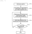
- FIG. 7 is a flowchart for describing a procedure of processing and observing the sample according to the present embodiment.
- FIG. 8 is a flowchart for describing a procedure of processing and observing the sample according to a comparative example (related art example).
- FIG. 9 is a view illustrating an example of an external configuration of a side entry type sample holder 900 according to a second embodiment.
- FIGS. 10A and 10B are sectional views of the side entry type sample holder 900 on a plane 903 of FIG. 9 .
- FIG. 11 is a view illustrating an aspect in which the tip portion 32 is completely exposed and the tip portion 32 is rotated about a rotation shaft 33 as a center to be in a vertical state.
- FIG. 12 is a view illustrating an aspect in which the side entry type sample holder 30 is attached to an observation apparatus (not illustrated) to observe a processing surface 603 .
- a side entry type sample holder includes a grip, a sample holder main body extending from the grip, a tip portion which is connected to the sample holder main body and provided with a sample table for fixing a sample, and a mechanism which changes a relative positional relationship of the sample fixed to the sample table with an irradiation direction of the ion beam, and causes the tip portion to avoid irradiation with the ion beam during the sample processing.
- the tip portion of the sample holder moves to a position at which an irradiation with the ion beam can be avoided (takes a refuge state), the tip portion can be prevented from being damaged due to exposure to the ion beam.
- the mechanism rotates the tip portion toward a direction opposite to a direction in which the ion source of an ion milling apparatus has been provided, from a state where the tip portion is horizontal to the sample holder main body.
- the mechanism includes a first shaft that is housed inside the sample holder main body, extends in a direction from the connecting portion to the grip, and has a first gear and a second shaft that has the same axis as the rotation shaft of the tip portion and has a second gear. Then, an operation is performed in such a manner that when a rotational force for rotating the first shaft is applied around an axis of the first shaft, the rotational force is transmitted to the second gear via the first gear to rotate the second shaft. Accordingly, the tip portion rotates so as to be away from the ion source and transits to a state where the tip portion becomes perpendicular to the sample holder main body, from a state of being horizontal to the sample holder main body.
- FIG. 1 is a view illustrating a schematic configuration of an ion milling apparatus 1 according to the present embodiment.
- the ion milling apparatus 1 includes a sample chamber 10 , a stage 20 , a side entry type sample holder 30 , a motor 40 , a control unit 50 , and an ion gun 60 .
- the ion gun 60 irradiates a target (sample) with an unfocused ion beam to process the sample.
- the sample chamber 10 can be evacuated by using a vacuum evacuation device (not illustrated).
- the sample chamber 10 is provided with a flare prevention diaphragm 11 .
- the flare prevention diaphragm is for preventing a part other than a sample placed on the side entry type sample holder 30 and the shielding plate (see FIG. 2 ) from being irradiated with a diffused ion beam.
- the stage 20 is configured so that the side entry type sample holder 30 can be attached to the sample chamber 10 without releasing the vacuum of the sample chamber 10 .
- the stage 20 is configured so that the side entry type sample holder 30 can be extracted from the sample chamber 10 without breaking the vacuum of the sample chamber 10 .
- the stage 20 is provided with a stage side gear 21 and is configured so that the stage side gear 21 meshes with a motor side gear 41 of the motor 40 . Then, when the motor rotates, the rotational force thereof is transmitted to the stage side gear 21 via the motor side gear 41 to rotate the rotation base 22 of the stage 20 .
- the motor 40 , a motor side gear 41 , and the stage side gear 21 are collectively referred to as a “swing mechanism”.
- the rotation base 22 Since the rotation base 22 is in close contact with the side entry type sample holder 30 , when the rotation base 22 rotates, the side entry type sample holder 30 also rotates about the rotation shaft 31 (rotates by predetermined angles respectively in a direction clockwise and counterclockwise) according to the rotation. A rotation speed and a rotation angle of the motor 40 are controlled by the control unit (control unit: for example, a computer) 50 .
- the rotation is also referred to as a swing. According to the rotation, the irradiation angle of the ion beam with which the ion gun 60 performs irradiation can be changed to obtain an effect of preventing streaks from being formed on the processing surface of the sample.
- the rotation angle (swing angle) ⁇ is set to, for example, approximately ⁇ 40 degrees ⁇ approximately +40 degrees.
- the an input device or a display device (not illustrated) is connected to the control unit 50 and an operator can instruct the rotation amount (swing amount) or a speed of the side entry type sample holder 30 using the input device.
- the motor 40 and the control unit 50 for driving the motor 40 may not be integrated with the stage 20 .
- the tip portion (pivot) 32 is configured so that a horizontal state can be changed to a vertical state about a rotation shaft 33 as the center (the rotation mechanism will be described later).
- a horizontal state can be changed to a vertical state about a rotation shaft 33 as the center (the rotation mechanism will be described later).
- the tip portion 32 becomes in the vertical state (a state in FIG. 1 ).
- the knob 36 is rotated counterclockwise, the tip portion 32 returns to the horizontal state.
- the tip portion 32 When the side entry type sample holder is inserted into the stage 20 , the tip portion 32 is kept in the horizontal state, and after insertion, the tip portion 32 is changed to the vertical state as shown in the drawing during sample processing. Then, the irradiation is performed with the ion beam and the sample placed on an end of the side entry type sample holder (specifically, near the rotation shaft 33 ) is processed with the ion beam via the flare prevention diaphragm 11 .
- FIG. 2 is a view illustrating an external configuration of a peripheral portion of the tip portion 32 of the side entry type sample holder 30 according to the present embodiment.
- FIG. 2( a ) illustrates a state (horizontal state) when the side entry type sample holder 30 is inserted into or extracted from the stage 20 .
- FIG. 2( b ) illustrates a state (vertical state) when the sample placed on the side entry type sample holder 30 is processed by the ion beam.
- a sample table 204 is provided (fixed), and a sample 203 is placed on the sample table 204 .
- a shielding plate 202 is attached to an upper surface of the sample 203 .
- a side surface of the sample 203 protrudes slightly (for example, by the amount (of milling) to be processed) from the shielding plate 202 and the sample table 204 .
- a side surface portion 2041 of the sample table 204 and a processing surface (processing target surface) 206 of the sample face an ion beam irradiation direction 200 .
- the tip portion 32 when processing the sample 203 , the tip portion 32 is rotated about the rotation axis 33 as the center to change the state to the vertical state. Since the sample table 204 is fixed to the tip portion 32 , the stage of the sample table 204 is also changed as the same along with the change of the state of the tip portion 32 .
- the side surface portion 2041 of the sample table 204 faces the ion beam irradiation direction 200 , but when the tip portion 32 is changed to the vertical state, the side surface portion 2041 becomes in a state parallel with the ion beam irradiation direction 200 .
- the state of the sample is also changed.
- the processing surface 206 of the specimen 203 becomes in a state of parallel with the ion beam irradiation direction 200 , from a state of vertical thereto.
- a unit for adjusting a position of the shielding plate 202 by precision micromanipulator such as a one-or-more directions (axes) micrometer or the like may be provided.
- FIG. 3 is a view illustrating a configuration (side surface) of a side entry type sample holder according to the present embodiment.
- FIG. 3( a ) illustrates an aspect of a state (horizontal state) when the tip portion 32 is not rotated.
- FIG. 3( b ) illustrates an aspect of a state (vertical state) when the tip portion 32 is rotated.
- the side entry type sample holder 30 includes a grip 34 , a sample holder main body 35 extending from the grip 34 , the tip portion 32 which is connected to the sample holder main body and provided with the sample table 204 for fixing a sample.
- a shaft 301 is connected to the knob 36 , and the shaft 301 extends from an inside of the side entry type sample holder 30 to the vicinity of the rotation shaft 33 .
- the shaft 301 When the knob 36 is rotated, for example, in a clockwise direction 302 , the shaft 301 also rotates in the clockwise direction 302 .
- the tip portion 32 is folded in a downward direction 303 about the rotation shaft 33 as the center by the tip portion rotation mechanism (which will be described later using FIG. 4 ) to be the vertical state ( FIG. 3( b ) ).
- the tip portion 32 is irradiated at the time of rotated state (vertical state) with the ion beam and the sample 203 placed on the sample table 204 is processed. During processing the sample 203 , the tip portion 32 faces the downward direction 303 . Therefore, the tip portion is not exposed to the ion beam and the damage to the tip portion 32 can be prevented.
- the shaft 301 When the knob 36 is rotated in a counterclockwise direction 305 after the processing of the sample 203 is completed, the shaft 301 also similarly rotates in the counterclockwise direction 305 . Then, the tip portion rises in an upward direction 306 about the rotation shaft 33 as the center by the tip portion 32 rotation mechanism described later to return to the horizontal state ( FIG. 3( a ) ).
- a height of the upper tip portion (processing target surface 206 ) of the sample 203 is lower than the height of the uppermost portion of the sample holder main body 305 . Accordingly, even when the side entry type sample holder 30 is subjected to an inserting and extracting operation with respect to the stage 20 , the sample 203 , the sample table 204 , and the shielding 202 do not interfere with the inserting and extracting operation.
- FIG. 4 is a view illustrating a configuration of the tip portion rotation mechanism provided in the side entry type sample holder 30 according to the present embodiment.
- FIG. 4( a ) is a top view of the side entry type sample holder 30 .
- FIG. 4( b ) illustrates a configuration of a main part of the tip portion rotation mechanism.
- the shaft 301 extends from the knob 36 to the vicinity of the rotation shaft 33 .
- a shaft 402 is provided on a portion of the rotation shaft 33 so as to traverse a side surface of the side entry type sample holder 30 . That is, the center of the shaft 401 coincides with the center of the rotation shaft 33 . Then, by rotating the shaft 401 , the state of the tip portion 32 transitions between the horizontal state and the vertical state. The rotation of the shaft 401 is realized by rotating the shaft 301 .
- the mechanism illustrated in FIG. 4( b ) realizes such an operation.
- a bevel gear 402 is attached to an end of the shaft 301 .
- a bevel gear 403 meshing with the bevel gear 402 is also attached to the shaft 401 .
- the shaft 301 is rotated clockwise by the knob 36
- the bevel gear 402 provided on the tip portion of the shaft 301 also rotates clockwise.
- the bevel gear 403 meshing with the bevel gear 402 rotates in a direction of an arrow 404 , according to this, the shaft 401 also rotates in the direction of the arrow 404 .
- the tip portion 32 is displaced from the horizontal state to the vertical state. If the knob 36 is rotated counterclockwise, according to an opposite operation, the tip portion 32 returns to the horizontal state from the vertical state.
- FIG. 5 is a view illustrating an aspect when a sample 203 is processed by using the side entry type sample holder 30 according to the present embodiment. Substantially, the flare prevention diaphragm 11 that regulates an irradiation size of an ion beam 501 is provided above the shield plate 202 .
- the tip portion 32 of the side entry type sample holder 30 becomes to the vertical state, that is, to be parallel to an ion beam irradiation direction.
- the processing surface (processing target surface) 206 of the sample 203 also becomes parallel to the ion beam irradiation direction.
- the processing surface is scraped (the shielding plate 202 may be scraped together in some cases) and the processing surface is exposed.
- the side entry type sample holder 30 is rotated (swung) around the rotation shaft 31 by a predetermined angle by the swing mechanism described above (see FIG.
- the sample 203 can be swung at the same time. Accordingly, it is possible to prevent stripes from being formed on the processing surface of the sample 203 , by the ion beam 501 .
- the tip portion 32 can be retracted downward during processing, the tip portion 32 can be prevented from being irradiated with the ion beam 501 . Accordingly, it is possible to avoid a situation that the tip portion 32 is damaged by being scraped by the ion beam 501 .
- FIG. 6 is a view illustrating an aspect when a processing surface (a processed surface) of the sample by using the side entry type sample holder 30 according to the present embodiment.
- the tip portion 32 of the side entry type sample holder 30 is set to the horizontal state to be extracted from the stage 20 of the ion milling apparatus 1 , and attached to an electron microscope apparatus (the entire apparatus is not illustrated).
- a processing surface (a processed surface) 603 of the sample 203 faces an electron gun 601 . Therefore, the processing surface 603 can be observed by being irradiated with an electron beam 602 as it is.
- an electron microscope is used as an example of the observation apparatus, but the processing surface 603 may be observed using another observation apparatus.
- FIG. 7 is a flowchart for describing a procedure of processing and observing the sample according to the present embodiment.
- an appropriate size for example, a size of approximately 5 mm ⁇ 5 mm. If the cut surface has unevenness, the surface is treated as even as possible.
- the operator places the pretreated sample 203 on the sample table 204 (side entry sample table for sectional observation) of the side entry type sample holder 30 . Then the operator covers an upper side of the sample 203 with the shielding plate 202 , and fixes the sample 203 and the shielding plate 202 to the sample table 204 . At this time, an end portion of the sample is caused to be slightly projected from the sample stage 204 and the shielding plate 202 . The amount to be projected is approximately equal to the amount to be removed by the ion milling. Since a position of the sample is uniquely determined when using the side entry type sample holder 30 according to the present embodiment, it is not required to adjust a sample processing position.
- the operator inserts the side entry type sample holder 30 into the stage 20 .
- the operator changes the state of the tip portion 32 of the side entry type sample holder 30 to the vertical state from the horizontal (see FIG. 2 ). Then, a section ion milling processing is performed inside the sample chamber 10 of the ion milling apparatus 1 .
- the side entry type sample holder 30 is controlled to rotate about the shaft 31 as the center clockwise and counterclockwise by predetermined angle by the swing mechanism described above, thereby preventing streaks from being formed on the processing surface (processing target surface) 206 .
- the stated of the tip portion 32 is changed to the horizontal state from the vertical state, and the side entry type sample holder 30 is extracted from the stage 20 .
- the operator inserts the side entry type sample holder 30 , on which the processed sample is placed, into the observation apparatus (electron microscope apparatus).
- the tip portion 32 is kept in the horizontal state, and the processing surface (a processed surface) 603 is caused to face the electron gun 601 (so that the electron beam 602 and the processing surface 603 are substantially vertical), the processing surface 603 is irradiated with the electron beam 602 , and the state of the processing surface 603 is observed.
- the operator extracts the side entry type sample holder 30 from the observation apparatus, inserts the side entry type sample holder 30 into the stage 20 of the ion milling apparatus 1 again to perform the ion milling processing and observation. The operator repeats the above processing and observation until the desired observation result is obtained.
- FIG. 8 is a flowchart for describing a procedure of processing and observing the sample according to a comparative example (related art example).
- the operator pretreats the sample. Specifically, the sample is cut into an appropriate size (for example, a size of approximately 5 mm ⁇ 5 mm). If the cut surface has unevenness, the surface is treated as even as possible.
- an appropriate size for example, a size of approximately 5 mm ⁇ 5 mm.
- the operator fixes the pretreated sample to the sample table for section milling.
- the operator adjusts the position of the sample so that a predetermined position of the sample is irradiated with the ion beam, using a processing position adjustment mechanism (XY axis position adjustment) provided on the sample table.
- a processing position adjustment mechanism XY axis position adjustment
- the operator performs the section ion milling processing inside the sample chamber of the ion milling apparatus.
- the operator removes the processed sample from the sample table for section milling.
- the operator fixes the sample removed in Step 805 to the sample table of the side entry type sample holder for sectional observation to insert the holder to the observation apparatus (electron microscope).
- the operator observes the processing surface of the sample with the observation apparatus.
- Step 808 the operator extracts the side entry type sample holder for sectional observation from the observation apparatus and removes the sample from the sample table of the holder.
- the operator repeats operations of the processing and observation from Steps 802 to 808 until the desired observation result is obtained.
- a second embodiment relates to a side entry type sample holder including a cap cover which is provided on the tip portion 32 and is for sealing (protecting) the sample 203 (including before and after processing) attached to the sample table 204 .
- a point different from the configuration of the first embodiment is that the cap cover for sealing (protecting) the sample 203 attached to the tip portion 32 is added.
- FIG. 9 is a view illustrating an example of an external configuration of a side entry type sample holder 900 according to the second embodiment.
- FIG. 10 is a sectional view of the side entry type sample holder 900 on a plane 903 of FIG. 9 .
- FIG. 10A illustrates a state where the cap cover completely covers the tip portion 32 .
- FIG. 10B illustrates a view illustrating a middle state of moving the cap cover until the sample 203 is exposed.
- the side entry type sample holder 900 includes cap bases 901 formed by, for example, a circular plate (which may also be an elliptic plate) and a cap movable portion 902 formed by, for example, a cylinder (which may also adopt a pipe shape other than a cylindrical shape), in the vicinity of a position of the tip portion 32 on which the sample 203 is placed.
- each cap base 901 is fixed to the tip portion 32 and the holder main body 35 . Since the cap movable portion 902 is formed as the cylinder, it is possible to operate so as to seal a space inside the cap base 901 .
- an operation mechanism of the cap movable portion 902 may be a type of sliding in a plane perpendicular to the irradiation direction of the electron beam 602 , and may be a type of rotating along a rotation axis by providing the rotation axis.
- An operation method of the cap movable portion 902 may be, for example, a method of moving automatically by providing a motor or the like, and also be a method of performing an operation from the outside of the sample chamber 10 by providing a rotation introduction device or the like on the side entry type sample holder 30 .
- a manipulator or the like may be provided to a tip of the holder to perform operation by the manipulator. Further, various operation mechanisms and operation methods can be adopted.
- FIG. 11 is a view illustrating an aspect in which the tip portion 32 is completely exposed and the tip portion 32 is rotated about a rotation shaft 33 as the center to be in a vertical state.
- the tip portion 32 can be folded in the downward direction 303 about the rotation shaft 33 as the center using the tip portion rotation mechanism as illustrated in the first embodiment so as to be in the vertical state.
- the tip portion is set to the vertical state, whereby the placed sample 203 can be processed with the ion beam 501 .
- the cap movable portion 902 is in a completely retracted state (a state where the sample 203 is exposed in the space of the sample chamber), the tip portion 32 and the cap movable portion 902 do not interfere with each other.
- the tip portion 32 After processing the sample 203 , the tip portion 32 returns to an original position thereof (from the vertical state to the horizontal state). Next, by operating the operation mechanism described above, the operator (user) moves the cap movable portion 902 in an arrow X1 direction until the cap movable portion 902 completely covers the sample 203 (which has been processed) placed on the sample table 204 of the tip portion. Thereafter, the operator extracts the side entry type sample holder 30 from the sample chamber 10 (see FIG. 1 ) and attaches the side entry type sample holder 30 to an observation apparatus (not illustrated). Accordingly, it is possible to observe the ion beam 603 of the sample 203 .
- the cap base 901 is desirably made of a material that is difficult to be scraped off by the ion beam 501 .
- FIG. 12 is a view illustrating an aspect in which the side entry type sample holder 30 is attached to an observation apparatus (not illustrated) to observe the processing surface 603 .
- the side entry type sample holder 30 taken out from the sample chamber 10 of the ion milling apparatus 1 is attached to (inserted into) the observation apparatus (not illustrated).
- the operator operates the movement mechanism of the cap movable portion 902 to move the cap movable portion 902 in an arrow X2 direction to a position where the processing surface 603 of the sample 203 can be observed (or to the completely retracted position of the cap movable portion 902 ).
- the operator observes the processing surface 603 by irradiating the processing surface 603 of the sample 203 with the electron beam 602 .
- a sample holder (side entry type sample holder) according to the present embodiment includes a grip, a sample holder main body extending from the grip, a tip portion which is connected to the sample holder main body and provided with a sample table for fixing a sample, and a mechanism which changes a relative positional relationship of the processing surface of the sample fixed to the sample table with an irradiation direction of the ion beam, and causes the tip portion to avoid irradiation with the ion beam during the sample processing. According to this, it is possible to avoid that the tip portion (pivot) of the holder is damaged by being exposed to the ion beam during processing.
- the throughput can be improved.
- the mechanism rotates the tip portion toward a direction opposite to a direction in which the ion source that performs irradiation with the ion beam has been provided, from a state where the tip portion is horizontal to the sample holder main body.
- the tip portion rotates about a rotation shaft provided at a connecting portion between the tip portion and the sample holder main body. It is possible to prevent the tip portion from being exposed to the ion beam, with such a simple configuration.
- the mechanism includes a first shaft that is housed inside the sample holder main body, extends in a direction from the connecting portion between the tip portion and the sample holder to the grip, and has a first gear and a second shaft that has the same axis as the rotation shaft of the tip portion.
- the first shaft has a first gear and the second shaft has a second gear, respectively. Then, when a rotational force for rotating the first shaft is applied around an axis of the first shaft, the rotational force is transmitted to the second gear via the first gear to rotate the second shaft. Since the second shaft is attached to the tip portion, the tip portion also rotates in the same manner, by rotating the second shaft. Since such a simple configuration can be adopted, it is possible to ensure the durability of the mechanism which rotates the tip portion.
- the sample table fixes the sample so that the processing surface of the sample faces the ion source that performs irradiation with the ion beam.
- the sample table fixes the sample so that the processing surface becomes horizontal to the irradiation direction of the ion beam. That is, a posture of the tip portion is changed by approximately 90 degrees by the mechanism, accordingly, a posture of the sample fixed to the tip portion is changed by approximately 90 degrees.
- the ion milling apparatus further includes a swing mechanism that rotates the tip portion of the sample holder by predetermined angle clockwise and counterclockwise about an axis of the sample holder main body, in addition to having the sample holder described above.
- the swing mechanism includes a motor, a control unit that controls a rotation of the motor, and a stage side gear that meshes with a gear of the motor and is provided outside the stage.
- the stage rotates by a predetermined angle clockwise and counterclockwise about the axis of the sample holder according to the rotation of the motor, thereby rotating the sample holder attached to the stage by the predetermined angle. According to this, it is possible to prevent the streaks from being formed on the processing surface when processing the sample with the ion beam.
- a sample processing method includes: a step of performing predetermined preparing on the sample (cutting the sample or grinding the processing surface to obtain a desired sample size); a step of fixing the sample to a sample table provided on the tip portion of the sample holder so that the processing surface of the sample faces an ion source when inserting the side entry type sample holder into the sample chamber of the ion milling apparatus (at this time, it is desirable that the shielding plate is placed on an upper face of the sample); a step of inserting the sample holder into the sample chamber of the ion milling apparatus; a step of causing the processing surface of the sample fixed to the sample table to be parallel to an irradiation direction of the ion beam by rotating the tip portion of the sample holder to a side opposite to a direction in which the ion source is provided; a step of irradiating the sample with the ion beam to process the sample; a step of changing the processing surface from a state parallel to the irradiation
- a swing mechanism that the ion milling apparatus has, may rotate the tip portion of the sample holder by predetermined angle clockwise and counterclockwise about an axis of the sample holder main body. Accordingly, it is possible to prevent stripes from being formed on the processing surface of the sample due to the irradiation with the ion beam.
- a sample observing method includes: a step of inserting the sample holder (the tip portion and the sample holder main body are in the horizontal state) extracted from the sample chamber of the ion milling apparatus into the observation apparatus while being in a state of attaching the sample to the sample holder; and a step of observing the processing surface of the sample using the observation apparatus.
- the sample holder used here includes a grip, a sample holder main body extending from the grip, the tip portion which is connected to the sample holder main body and provided with the sample table, and a mechanism which rotates the tip portion toward a direction opposite to a direction in which the charged particle beam source of the observation apparatus is provided from a state where the tip portion is horizontal to the sample holder main body and changes a relative positional relationship between the processing surface of the sample fixed to the sample table and the irradiation direction of the charged particle beam.
- the tip portion is horizontal to the sample holder main body and the processing surface of the sample is in a state of facing the charged particle beam source of the observation apparatus.
- the tip portion is not rotated by the mechanism of the sample holder.
- steps for observation can be simplified and the throughput can be improved.
- the sample holder can be extracted from the observation apparatus to insert into the ion milling apparatus as it is. Therefore, the procedure of processing and observation is simple and usability is extremely good. Further, since it is not required to remove the sample from the sample holder, it is possible to reduce a concern that the sample is damaged.
Landscapes
- Chemical & Material Sciences (AREA)
- Analytical Chemistry (AREA)
- Physics & Mathematics (AREA)
- Plasma & Fusion (AREA)
- Engineering & Computer Science (AREA)
- General Health & Medical Sciences (AREA)
- Biochemistry (AREA)
- General Physics & Mathematics (AREA)
- Immunology (AREA)
- Pathology (AREA)
- Life Sciences & Earth Sciences (AREA)
- Health & Medical Sciences (AREA)
- Sampling And Sample Adjustment (AREA)
Abstract
Description
- PTL 1: JP-A-11-258130
-
- 1: Ion milling apparatus
- 10: Sample chamber
- 11: Flare prevention diaphragm
- 20: Stage
- 21: Stage side gear
- 22: Rotation base
- 30: Side entry type sample holder
- 31: Rotation shaft (Sample holder main body)
- 32: Tip portion
- 33: Rotation shaft (Tip portion)
- 34: Grip
- 35: Sample holder main body
- 36: Knob
- 40: Motor
- 41: Motor side gear
- 50: Control unit
- 60: Ion gun
- 202: Shielding plate
- 203: Sample
- 206: Processing surface
Claims (11)
Applications Claiming Priority (1)
| Application Number | Priority Date | Filing Date | Title |
|---|---|---|---|
| PCT/JP2016/053165 WO2017134764A1 (en) | 2016-02-03 | 2016-02-03 | Sample holder, ion milling apparatus, sample processing method, sample observation method, and sample processing/observation method |
Publications (2)
| Publication Number | Publication Date |
|---|---|
| US20190033182A1 US20190033182A1 (en) | 2019-01-31 |
| US11226273B2 true US11226273B2 (en) | 2022-01-18 |
Family
ID=59499597
Family Applications (1)
| Application Number | Title | Priority Date | Filing Date |
|---|---|---|---|
| US16/070,468 Active 2037-10-26 US11226273B2 (en) | 2016-02-03 | 2016-02-03 | Sample holder, ion milling apparatus, sample processing method, sample observing method, and sample processing and observing method |
Country Status (6)
| Country | Link |
|---|---|
| US (1) | US11226273B2 (en) |
| JP (1) | JP6533312B2 (en) |
| KR (1) | KR102079069B1 (en) |
| CN (1) | CN108475607B (en) |
| DE (1) | DE112016005621B4 (en) |
| WO (1) | WO2017134764A1 (en) |
Cited By (2)
| Publication number | Priority date | Publication date | Assignee | Title |
|---|---|---|---|---|
| US20220051870A1 (en) * | 2020-08-13 | 2022-02-17 | Jeol Ltd. | Ion Milling Apparatus and Sample Holder |
| KR102404424B1 (en) * | 2020-12-10 | 2022-06-02 | 에이치비솔루션(주) | Sample holder and one touch transfer device |
Families Citing this family (3)
| Publication number | Priority date | Publication date | Assignee | Title |
|---|---|---|---|---|
| JP6843790B2 (en) * | 2018-03-13 | 2021-03-17 | 日本電子株式会社 | Ion milling device and sample holder |
| KR102080671B1 (en) * | 2019-05-17 | 2020-02-25 | (주)이엠아이티 | Sample holding device and sample manufacturing method therefor |
| JP7204931B2 (en) * | 2019-08-23 | 2023-01-16 | 株式会社日立ハイテク | Ion milling device and milling method using the same |
Citations (8)
| Publication number | Priority date | Publication date | Assignee | Title |
|---|---|---|---|---|
| JPH11258130A (en) | 1998-03-10 | 1999-09-24 | Hitachi Ltd | Sample preparation apparatus and sample preparation method |
| JP2002231171A (en) | 2001-01-29 | 2002-08-16 | Nippon Light Metal Co Ltd | Sample holding device |
| US20020166976A1 (en) | 2001-05-08 | 2002-11-14 | Masakazu Sugaya | Beam as well as method and equipment for specimen fabrication |
| US20020194938A1 (en) | 2001-06-20 | 2002-12-26 | Samsung Electronics Co., Ltd. | Sample holder and auxiliary apparatus |
| JP2005043382A (en) | 2004-11-15 | 2005-02-17 | Hitachi Ltd | Sample preparation apparatus for three-dimensional structure observation, electron microscope and method thereof |
| JP2013080605A (en) | 2011-10-03 | 2013-05-02 | Hironari Miyazaki | Sample holder tip, sample holder, and manufacturing method of sample holder tip |
| DE112011103860T5 (en) | 2010-11-22 | 2013-08-14 | Hitachi High-Technologies Corporation | Ion etching apparatus and ion etching processing method |
| US20130220806A1 (en) * | 2010-11-05 | 2013-08-29 | Hitachi High-Technologies Corporation | Ion milling device |
Family Cites Families (4)
| Publication number | Priority date | Publication date | Assignee | Title |
|---|---|---|---|---|
| JP2003151479A (en) * | 2001-11-15 | 2003-05-23 | Hitachi Ltd | Charge neutralization control method and charged particle beam apparatus using the same |
| KR20080076044A (en) * | 2007-02-14 | 2008-08-20 | 삼성전자주식회사 | Specimen holder |
| JP4433092B2 (en) * | 2009-03-05 | 2010-03-17 | 株式会社日立製作所 | Three-dimensional structure observation method |
| WO2015153464A1 (en) * | 2014-04-02 | 2015-10-08 | The Board Of Trustees Of The Leland Stanford Junior University | An apparatus and method for sub-micrometer elemental image analysis by mass spectrometry |
-
2016
- 2016-02-03 CN CN201680077768.6A patent/CN108475607B/en active Active
- 2016-02-03 DE DE112016005621.4T patent/DE112016005621B4/en active Active
- 2016-02-03 JP JP2017565015A patent/JP6533312B2/en active Active
- 2016-02-03 US US16/070,468 patent/US11226273B2/en active Active
- 2016-02-03 WO PCT/JP2016/053165 patent/WO2017134764A1/en not_active Ceased
- 2016-02-03 KR KR1020187018629A patent/KR102079069B1/en active Active
Patent Citations (10)
| Publication number | Priority date | Publication date | Assignee | Title |
|---|---|---|---|---|
| JPH11258130A (en) | 1998-03-10 | 1999-09-24 | Hitachi Ltd | Sample preparation apparatus and sample preparation method |
| JP2002231171A (en) | 2001-01-29 | 2002-08-16 | Nippon Light Metal Co Ltd | Sample holding device |
| US20020166976A1 (en) | 2001-05-08 | 2002-11-14 | Masakazu Sugaya | Beam as well as method and equipment for specimen fabrication |
| US20020194938A1 (en) | 2001-06-20 | 2002-12-26 | Samsung Electronics Co., Ltd. | Sample holder and auxiliary apparatus |
| KR20020096551A (en) | 2001-06-20 | 2002-12-31 | 삼성전자 주식회사 | Sample holder, auxiliary apparatus for holding sample in the sample holder and Method of holding sample using the same |
| JP2005043382A (en) | 2004-11-15 | 2005-02-17 | Hitachi Ltd | Sample preparation apparatus for three-dimensional structure observation, electron microscope and method thereof |
| US20130220806A1 (en) * | 2010-11-05 | 2013-08-29 | Hitachi High-Technologies Corporation | Ion milling device |
| DE112011103860T5 (en) | 2010-11-22 | 2013-08-14 | Hitachi High-Technologies Corporation | Ion etching apparatus and ion etching processing method |
| US20130240353A1 (en) | 2010-11-22 | 2013-09-19 | Hitachi High-Technologies Corporation | Ion milling device and ion milling processing method |
| JP2013080605A (en) | 2011-10-03 | 2013-05-02 | Hironari Miyazaki | Sample holder tip, sample holder, and manufacturing method of sample holder tip |
Non-Patent Citations (5)
| Title |
|---|
| German-language Office Action issued in German Application No. 11 2016 005 621.4 dated Jun. 25, 2021 (eight (8) pages). |
| International Search Report (PCT/ISA/210) issued in PCT Application No. PCT/JP2016/053165 dated May 10, 2016 with English translation (two (2) pages). |
| Japanese-language Written Opinion (PCT/ISA/237) issued in PCT Application No. PCT/JP2016/053165 dated May 10, 2016 (three (3) pages). |
| Korean-language Office Action issued in counterpart Korean Application No. 10-2018-7018629 dated Jul. 1, 2019 with English translation (eight pages). |
| Machine Translation of 2002-231171 (Year: 2002). * |
Cited By (3)
| Publication number | Priority date | Publication date | Assignee | Title |
|---|---|---|---|---|
| US20220051870A1 (en) * | 2020-08-13 | 2022-02-17 | Jeol Ltd. | Ion Milling Apparatus and Sample Holder |
| US11562886B2 (en) * | 2020-08-14 | 2023-01-24 | Jeol Ltd. | Ion milling apparatus and sample holder |
| KR102404424B1 (en) * | 2020-12-10 | 2022-06-02 | 에이치비솔루션(주) | Sample holder and one touch transfer device |
Also Published As
| Publication number | Publication date |
|---|---|
| JP6533312B2 (en) | 2019-06-19 |
| CN108475607A (en) | 2018-08-31 |
| US20190033182A1 (en) | 2019-01-31 |
| DE112016005621T5 (en) | 2020-07-23 |
| KR102079069B1 (en) | 2020-02-19 |
| JPWO2017134764A1 (en) | 2018-10-11 |
| DE112016005621B4 (en) | 2022-03-31 |
| CN108475607B (en) | 2019-11-19 |
| KR20180089469A (en) | 2018-08-08 |
| WO2017134764A1 (en) | 2017-08-10 |
Similar Documents
| Publication | Publication Date | Title |
|---|---|---|
| US11226273B2 (en) | Sample holder, ion milling apparatus, sample processing method, sample observing method, and sample processing and observing method | |
| CN107084869B (en) | High throughput TEM fabrication process and hardware for backside thinning of cross-sectional view thin layers | |
| US7718981B2 (en) | Composite charged-particle beam system | |
| EP2558839B1 (en) | Ion beam sample preparation apparatus and methods | |
| US8716683B2 (en) | Ion beam processing system and sample processing method | |
| JP2004093353A (en) | Sample preparation device | |
| JP6359351B2 (en) | Preparation of planar sample | |
| JP2018200815A (en) | Ion milling device and specimen holder | |
| JP2019160575A (en) | Ion milling device and sample holder | |
| JP2013201028A (en) | Ion milling device | |
| KR20220011079A (en) | Ion milling apparatus and method of manufacturing sample | |
| US7755044B2 (en) | Apparatus for working and observing samples and method of working and observing cross sections | |
| EP3101679A1 (en) | Dynamic creation of backup fiducials | |
| JP2009109236A (en) | Method for processing needle-shaped sample for atom probe and focused ion beam apparatus | |
| KR101903782B1 (en) | Method and system for preparing a lamella | |
| JP2017182923A (en) | Specimen holder and focused ion beam device | |
| JP2007014996A (en) | Ion milling apparatus and ion milling method | |
| JP2015228311A (en) | Sample holder | |
| EP3023763B1 (en) | Specimen preparation device | |
| US11476080B2 (en) | Device with at least one adjustable sample holder and method of changing holder tilt angle and method of preparing a lamella | |
| WO2016121080A1 (en) | Ion milling mask position adjustment method, electron microscope capable of adjusting mask position, mask adjustment device carried by sample stage, and sample mask part for ion milling device | |
| JP4675860B2 (en) | Ion milling apparatus and method | |
| JP6258826B2 (en) | Sample preparation equipment | |
| KR102935251B1 (en) | Thin film sample piece creating method and charged particle beam device | |
| EP2916121A1 (en) | Apparatus and method for sample preparation |
Legal Events
| Date | Code | Title | Description |
|---|---|---|---|
| FEPP | Fee payment procedure |
Free format text: ENTITY STATUS SET TO UNDISCOUNTED (ORIGINAL EVENT CODE: BIG.); ENTITY STATUS OF PATENT OWNER: LARGE ENTITY |
|
| AS | Assignment |
Owner name: HITACHI HIGH-TECHNOLOGIES CORPORATION, JAPAN Free format text: ASSIGNMENT OF ASSIGNORS INTEREST;ASSIGNORS:KAMINO, ATSUSHI;TAKASU, HISAYUKI;REEL/FRAME:046554/0317 Effective date: 20180613 |
|
| STPP | Information on status: patent application and granting procedure in general |
Free format text: DOCKETED NEW CASE - READY FOR EXAMINATION |
|
| AS | Assignment |
Owner name: HITACHI HIGH-TECH CORPORATION, JAPAN Free format text: CHANGE OF NAME;ASSIGNOR:HITACHI HIGH-TECHNOLOGIES CORPORATION;REEL/FRAME:052398/0249 Effective date: 20200212 |
|
| STPP | Information on status: patent application and granting procedure in general |
Free format text: NON FINAL ACTION MAILED |
|
| STPP | Information on status: patent application and granting procedure in general |
Free format text: RESPONSE TO NON-FINAL OFFICE ACTION ENTERED AND FORWARDED TO EXAMINER |
|
| STPP | Information on status: patent application and granting procedure in general |
Free format text: FINAL REJECTION MAILED |
|
| STPP | Information on status: patent application and granting procedure in general |
Free format text: DOCKETED NEW CASE - READY FOR EXAMINATION |
|
| STPP | Information on status: patent application and granting procedure in general |
Free format text: NOTICE OF ALLOWANCE MAILED -- APPLICATION RECEIVED IN OFFICE OF PUBLICATIONS |
|
| STPP | Information on status: patent application and granting procedure in general |
Free format text: PUBLICATIONS -- ISSUE FEE PAYMENT VERIFIED |
|
| STCF | Information on status: patent grant |
Free format text: PATENTED CASE |
|
| MAFP | Maintenance fee payment |
Free format text: PAYMENT OF MAINTENANCE FEE, 4TH YEAR, LARGE ENTITY (ORIGINAL EVENT CODE: M1551); ENTITY STATUS OF PATENT OWNER: LARGE ENTITY Year of fee payment: 4 |