JP6359351B2 - Preparation of planar sample - Google Patents
Preparation of planar sample Download PDFInfo
- Publication number
- JP6359351B2 JP6359351B2 JP2014122959A JP2014122959A JP6359351B2 JP 6359351 B2 JP6359351 B2 JP 6359351B2 JP 2014122959 A JP2014122959 A JP 2014122959A JP 2014122959 A JP2014122959 A JP 2014122959A JP 6359351 B2 JP6359351 B2 JP 6359351B2
- Authority
- JP
- Japan
- Prior art keywords
- sample
- workpiece
- ion beam
- probe
- flake
- Prior art date
- Legal status (The legal status is an assumption and is not a legal conclusion. Google has not performed a legal analysis and makes no representation as to the accuracy of the status listed.)
- Active
Links
Images


Classifications
-
- H—ELECTRICITY
- H01—ELECTRIC ELEMENTS
- H01J—ELECTRIC DISCHARGE TUBES OR DISCHARGE LAMPS
- H01J37/00—Discharge tubes with provision for introducing objects or material to be exposed to the discharge, e.g. for the purpose of examination or processing thereof
- H01J37/30—Electron-beam or ion-beam tubes for localised treatment of objects
- H01J37/317—Electron-beam or ion-beam tubes for localised treatment of objects for changing properties of the objects or for applying thin layers thereon, e.g. for ion implantation
-
- G—PHYSICS
- G01—MEASURING; TESTING
- G01N—INVESTIGATING OR ANALYSING MATERIALS BY DETERMINING THEIR CHEMICAL OR PHYSICAL PROPERTIES
- G01N1/00—Sampling; Preparing specimens for investigation
- G01N1/28—Preparing specimens for investigation including physical details of (bio-)chemical methods covered elsewhere, e.g. G01N33/50, C12Q
- G01N1/32—Polishing; Etching
-
- H—ELECTRICITY
- H01—ELECTRIC ELEMENTS
- H01J—ELECTRIC DISCHARGE TUBES OR DISCHARGE LAMPS
- H01J37/00—Discharge tubes with provision for introducing objects or material to be exposed to the discharge, e.g. for the purpose of examination or processing thereof
- H01J37/02—Details
- H01J37/20—Means for supporting or positioning the objects or the material; Means for adjusting diaphragms or lenses associated with the support
-
- H—ELECTRICITY
- H01—ELECTRIC ELEMENTS
- H01J—ELECTRIC DISCHARGE TUBES OR DISCHARGE LAMPS
- H01J37/00—Discharge tubes with provision for introducing objects or material to be exposed to the discharge, e.g. for the purpose of examination or processing thereof
- H01J37/26—Electron or ion microscopes; Electron or ion diffraction tubes
- H01J37/28—Electron or ion microscopes; Electron or ion diffraction tubes with scanning beams
-
- H—ELECTRICITY
- H01—ELECTRIC ELEMENTS
- H01J—ELECTRIC DISCHARGE TUBES OR DISCHARGE LAMPS
- H01J37/00—Discharge tubes with provision for introducing objects or material to be exposed to the discharge, e.g. for the purpose of examination or processing thereof
- H01J37/30—Electron-beam or ion-beam tubes for localised treatment of objects
- H01J37/302—Controlling tubes by external information, e.g. programme control
- H01J37/3023—Programme control
-
- H—ELECTRICITY
- H01—ELECTRIC ELEMENTS
- H01J—ELECTRIC DISCHARGE TUBES OR DISCHARGE LAMPS
- H01J37/00—Discharge tubes with provision for introducing objects or material to be exposed to the discharge, e.g. for the purpose of examination or processing thereof
- H01J37/30—Electron-beam or ion-beam tubes for localised treatment of objects
- H01J37/305—Electron-beam or ion-beam tubes for localised treatment of objects for casting, melting, evaporating or etching
- H01J37/3053—Electron-beam or ion-beam tubes for localised treatment of objects for casting, melting, evaporating or etching for evaporating or etching
-
- H—ELECTRICITY
- H01—ELECTRIC ELEMENTS
- H01J—ELECTRIC DISCHARGE TUBES OR DISCHARGE LAMPS
- H01J37/00—Discharge tubes with provision for introducing objects or material to be exposed to the discharge, e.g. for the purpose of examination or processing thereof
- H01J37/30—Electron-beam or ion-beam tubes for localised treatment of objects
- H01J37/317—Electron-beam or ion-beam tubes for localised treatment of objects for changing properties of the objects or for applying thin layers thereon, e.g. for ion implantation
- H01J37/3178—Electron-beam or ion-beam tubes for localised treatment of objects for changing properties of the objects or for applying thin layers thereon, e.g. for ion implantation for applying thin layers on objects
-
- H—ELECTRICITY
- H01—ELECTRIC ELEMENTS
- H01J—ELECTRIC DISCHARGE TUBES OR DISCHARGE LAMPS
- H01J2237/00—Discharge tubes exposing object to beam, e.g. for analysis treatment, etching, imaging
- H01J2237/26—Electron or ion microscopes
- H01J2237/28—Scanning microscopes
- H01J2237/2802—Transmission microscopes
-
- H—ELECTRICITY
- H01—ELECTRIC ELEMENTS
- H01J—ELECTRIC DISCHARGE TUBES OR DISCHARGE LAMPS
- H01J2237/00—Discharge tubes exposing object to beam, e.g. for analysis treatment, etching, imaging
- H01J2237/30—Electron or ion beam tubes for processing objects
- H01J2237/317—Processing objects on a microscale
- H01J2237/3174—Etching microareas
- H01J2237/31745—Etching microareas for preparing specimen to be viewed in microscopes or analyzed in microanalysers
-
- H—ELECTRICITY
- H01—ELECTRIC ELEMENTS
- H01J—ELECTRIC DISCHARGE TUBES OR DISCHARGE LAMPS
- H01J2237/00—Discharge tubes exposing object to beam, e.g. for analysis treatment, etching, imaging
- H01J2237/30—Electron or ion beam tubes for processing objects
- H01J2237/317—Processing objects on a microscale
- H01J2237/31749—Focused ion beam
Description
本発明は、荷電粒子ビーム・システムで観察する試料の調製に関する。 The present invention relates to the preparation of a sample for observation with a charged particle beam system.
走査イオン顕微鏡法、電子顕微鏡法などの荷電粒子ビーム顕微鏡法は、光学顕微鏡法よりもかなり高い分解能および大きな焦点深度を提供する。走査電子顕微鏡(SEM)では、1次電子ビームを微小なスポットに集束させ、観察しようとする表面をそのスポットで走査する。表面に1次電子ビームが衝突すると、その表面から2次電子が放出される。その2次電子を検出し、画像を形成する。このとき、画像のそれぞれの点の輝度は、その表面の対応するスポットにビームが衝突したときに検出された2次電子の数によって決定される。走査イオン顕微鏡法(SIM)は、走査電子顕微鏡法と似ているが、表面を走査し、2次電子を追い出す目的にイオン・ビームが使用される。 Charged particle beam microscopy, such as scanning ion microscopy and electron microscopy, provides significantly higher resolution and greater depth of focus than optical microscopy. In a scanning electron microscope (SEM), a primary electron beam is focused on a minute spot, and the surface to be observed is scanned with the spot. When the primary electron beam collides with the surface, secondary electrons are emitted from the surface. The secondary electrons are detected and an image is formed. At this time, the brightness of each point of the image is determined by the number of secondary electrons detected when the beam collides with the corresponding spot on the surface. Scanning ion microscopy (SIM) is similar to scanning electron microscopy, but uses an ion beam for the purpose of scanning the surface and expelling secondary electrons.
透過型電子顕微鏡(TEM)では、幅の広い電子ビームが試料に衝突し、試料を透過した電子を集束させて試料の画像を形成する。1次ビーム中の電子の多くが試料を透過し、反対側から出てくることを可能にするため、試料は十分に薄くなければならない。試料の厚さは通常、100nm未満である。 In a transmission electron microscope (TEM), a wide electron beam collides with a sample, and the electrons transmitted through the sample are focused to form an image of the sample. The sample must be thin enough to allow many of the electrons in the primary beam to penetrate the sample and emerge from the other side. The thickness of the sample is usually less than 100 nm.
透過型走査電子顕微鏡(STEM)では、1次電子ビームを微小なスポットに集束させ、そのスポットで試料表面を走査する。加工物を透過した電子を、試料の向こう側に置かれた電子検出器によって集める。画像のそれぞれの点の強度は、その表面の対応する点に1次ビームが衝突したときに集められた電子の数に対応する。 In a transmission scanning electron microscope (STEM), a primary electron beam is focused on a minute spot, and the sample surface is scanned with the spot. Electrons that have passed through the workpiece are collected by an electron detector placed across the sample. The intensity of each point in the image corresponds to the number of electrons collected when the primary beam collides with the corresponding point on the surface.
透過型電子顕微鏡(TEMまたはSTEM)で観察するためには試料が非常に薄くなければならないため、試料の調製は、繊細で時間のかかる作業となりうる。本明細書で使用する用語「TEM試料」はTEMまたはSTEM用の試料を指し、TEM用の試料を調製すると言うときには、STEMで観察するための試料を調製することも含まれると理解されるべきである。TEM試料を調製する1つの方法は、イオン・ビームを使用して加工物基板から試料を切り出す方法である。加工物から試料を完全に切り離す前または切り離した後に、試料にプローブを取り付ける。プローブは、例えば静電気、FIB堆積法または接着剤によって取り付けることができる。プローブに取り付けられた試料を、試料が抜き取られた加工物から引き離し、通常、FIB堆積法、静電気または接着剤を使用してTEMグリッドに取り付ける。 Sample preparation can be a delicate and time consuming task because the sample must be very thin to be observed with a transmission electron microscope (TEM or STEM). As used herein, the term “TEM sample” refers to a sample for TEM or STEM, and when preparing a sample for TEM, it should be understood to include preparing a sample for observation by STEM. It is. One method of preparing a TEM sample is to cut a sample from a workpiece substrate using an ion beam. Attach the probe to the sample before or after completely detaching the sample from the workpiece. The probe can be attached by, for example, static electricity, FIB deposition or adhesive. The sample attached to the probe is pulled away from the workpiece from which the sample has been removed and is typically attached to the TEM grid using FIB deposition, static electricity or adhesive.
図1は、部分的に円形の3mmのリングを含む通常のTEMグリッド100を示す。いくつかの用途では、試料104は、イオン・ビーム堆積法または接着剤によってTEMグリッドのフィンガ(finger)106に取り付けられる。試料は、フィンガ106から、TEM(図示せず)内で、電子ビームが、試料104を通り抜けて試料の下の検出器に至る障害物のない経路を有するように延びる。TEMグリッドは通常、TEM内の試料ホルダ上に、TEMグリッドの平面が電子ビームに対して直角になるように水平に取り付けられ、試料が観察される。
FIG. 1 shows a
いくつかのデュアル・ビーム・システムは、試料を抜き取る目的に使用することができるイオン・ビームと、SEMまたはSTEM観察に使用することができる電子ビームとを含む。いくつかのデュアル・ビーム・システムでは、FIBが、垂直線から、52度などのある角度だけ傾けられており、電子ビーム・カラムが垂直に配置されている。他のシステムでは、電子ビーム・カラムが傾けられており、FIBが垂直に配置されているかまたはやはり傾けられている。その上に試料が装着されたステージは通常、傾けることができ、いくつかのシステムではステージを最大約60度まで傾けることができる。 Some dual beam systems include an ion beam that can be used for sampling purposes and an electron beam that can be used for SEM or STEM observation. In some dual beam systems, the FIB is tilted from the vertical by an angle, such as 52 degrees, and the electron beam column is placed vertically. In other systems, the electron beam column is tilted and the FIB is positioned vertically or is also tilted. The stage on which the sample is mounted can typically be tilted, and in some systems the stage can be tilted up to about 60 degrees.
加工物上で試料がどのような向きにあるかによって、TEM試料を、「平面視(plan view)」試料または「断面視(cross−sectional view)」試料に大まかに分類することができる。試料の観察しようとする面が加工物の表面に対して平行である場合、その試料は「平面視」試料と呼ばれる。観察しようとする面が加工物表面に対して直角である場合、その試料は「断面視」試料と呼ばれる。 Depending on the orientation of the sample on the workpiece, the TEM sample can be roughly classified as a “plan view” sample or a “cross-section view” sample. If the surface to be observed of the sample is parallel to the surface of the workpiece, the sample is called a “plan view” sample. If the surface to be observed is perpendicular to the workpiece surface, the sample is called a “cross-sectional view” sample.
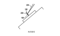
図2は、通常のプロセスを使用して加工物202から部分的に抜き取られた断面視TEM試料200を示す。イオン・ビーム204が、抜き取る試料の両側面にトレンチ206および208を切り、薄い薄片(ラメラ、lamella)210を残す。薄片210は、電子ビームによって観察する主表面212を有する。次いで、加工物202をイオン・ビームに対して傾け、試料200の側辺および底辺を切断することにより、試料200を切り離す。試料200を切り離す前または切り離した後に、プローブ216が試料200の頂部に付着し、試料をTEMグリッドへ運ぶ。図2は、1つの側辺のタブ218によってつながった、ほぼ完全に切り離された試料200を示している。図2は、タブ218を切断しようとしているイオン・ビーム204を示している。
FIG. 2 shows a
図2に示されているように、主表面212は垂直に配置されている。通常、薄片を運んでも薄片の向きは変化せず、そのため、試料200がTEM試料ホルダまで運ばれたときも薄片の主表面は依然として垂直のままである。図3に示されているように、TEMグリッド100の平面は通常、垂直に配置され、そのため、主表面212がグリッドの平面に対して平行に延びるような形で試料200をTEMグリッドに取り付けることができ、グリッドの構造は、グリッドがTEM内に装着されたときに電子の透過を妨害しない。イオン・ビームを使用して、抜き取った試料をイオン・ビーム堆積法によりTEMグリッドに取り付けることができる。取り付けた後、イオン・ビームを使用して試料200の面を薄くすることもできる。図3は、試料ステージ304上のグリッド支持体302内のTEMグリッド100に取り付けられている試料200を示す。試料200は、イオン・ビーム204およびノズル312からの堆積前駆体ガス310を使用してグリッドに取り付けられる。図4は、イオン・ビーム204に対して試料200が実質的に直角になり、その結果、イオン・ビームによって試料200を薄くすることができるように、ステージ304を回転させ、傾けた様子を示している。
As shown in FIG. 2, the
図5は、試料の面504を観察するために平面視試料502が抜き取られている加工物500を示す。反対方向からの2回の交差イオン・ビーム切削506Aおよび506Bによって試料502の下側を切削し、次いでイオン・ビームが側面508Aおよび508Bを切削して、試料502を含む加工物500の一部分を実質的に取り除く。試料502の頂部にプローブ510が取り付けられている。したがって、抜き取られた試料の向きは水平である。垂直に配置されたTEMグリッドに対して水平に試料が取り付けられた場合、試料はグリッドの平面に対して垂直に延び、グリッドはTEMの電子ビームを妨げることになる。水平に配置されたTEMグリッドに試料が装着された場合、観察する面504は上を向く。その場合、薄くするために、TEMグリッドを真空室から取り出し、TEMグリッドを裏返して試料502の裏側を露出させることなしに、従来のFIBシステムで平面視試料502の裏側を薄くすることは困難であろう。
FIG. 5 shows a
平面視TEM試料502の向きのこの問題はこれまで、平面視試料を取り付けるためにTEMグリッドを水平に配置することができ、次いで、薄くするために試料の裏側をイオン・ビームに対して垂直に提供することができるようにステージを180度裏返し、回転させることができる、「フリップ・ステージ(flip stage)」を使用することによって解決されてきた。フリップ・ステージは例えば、Asselbergs他の「Method for the manufacture and transmissive irradiation of a sample,and particle−optical system」という名称の米国特許第6,963,068号明細書に記載されており、従来のステージでは利用できない自由度を提供する。このようなフリップ・ステージは高価であり、全てのFIBシステムで使用できるわけではない。
This problem of orientation of the plan
また、平面視試料を、外位置(ex−situ)リフトアウト(lift out)に適したものにすることも望ましい。外位置リフトアウトは、薄い薄片をウェーハ内に残し、次いで、別のベンチトップ(bench−top)・システム内においてガラス針などの抜取りデバイスを使用して薄片を抜き取ることを含む。現在、完全なウェーハまたは類似の基板から外位置リフトアウト用の平面視試料を抜き取る方法はない。平面視試料の向きが、ウェーハの表面に対して実質的に水平な向きから、ウェーハの表面に対して実質的に垂直な向きに変化するように、平面視試料の向きを変化させる方法が求められている。 It is also desirable to make the sample in plan view suitable for ex-situ lift-out. Out-of-place lift-out involves leaving a thin flake in the wafer and then extracting the flake using a pulling device, such as a glass needle, in a separate bench-top system. Currently, there is no way to extract a planar sample for out-of-location liftout from a complete wafer or similar substrate. There is a need for a method for changing the orientation of the planar specimen so that the orientation of the planar specimen changes from a substantially horizontal orientation to the wafer surface to a substantially perpendicular orientation to the wafer surface. It has been.
本発明の目的は、荷電粒子ビーム試料の向きを変える方法および装置を提供することにある。 An object of the present invention is to provide a method and apparatus for changing the orientation of a charged particle beam sample.
この方法の実施形態は、試料ステージ平面を有する試料ステージ上に第1の加工物を配置するステップを含み、第1の加工物は、第1の向きを向いた薄片面を含む。試料は、第1の加工物から実質的に切り離されるように、イオン・ビームを使用して第1の加工物からミリングされる。プローブが試料に取り付けられ、このプローブは、シャフト軸を有するシャフトを含み、シャフト軸は、試料ステージ平面に対してあるシャフト角で配向され、シャフト角は、試料ステージ平面に対して垂直ではない。シャフト軸を軸にプローブをある回転角で回転させて、薄片面が第2の向きを向くようにする。試料は、試料がそこからミリングされた加工物である第1の加工物に取り付けられ、もしくは第1の加工物上に置かれるか、または試料がそこからミリングされなかった加工物である第2の加工物に取り付けられ、もしくは第2の加工物上に置かれる。試料をイオン・ビームを使用して薄くして、薄片面に沿った配向の薄片を形成する。 Embodiments of the method include disposing a first workpiece on a sample stage having a sample stage plane, the first workpiece including a laminar surface facing a first orientation. The sample is milled from the first workpiece using an ion beam so that it is substantially disconnected from the first workpiece. A probe is attached to the sample, the probe including a shaft having a shaft axis that is oriented at a shaft angle with respect to the sample stage plane, and the shaft angle is not perpendicular to the sample stage plane. The probe is rotated at a certain rotation angle about the shaft axis so that the flake surface faces the second direction. The sample is attached to or placed on a first workpiece from which the sample is milled, or a sample from which the sample has not been milled. Attached to a workpiece or placed on a second workpiece. The sample is thinned using an ion beam to form flakes oriented along the flake surface.
装置の諸実施形態は、イオン・ビーム・カラム、試料ステージ、プローブおよびコントローラを含む。試料ステージは、試料ステージ平面を含み、少なくとも2次元空間内で移動することができ、垂直軸を軸に回転することができる。プローブは、シャフト軸を軸に回転可能である。シャフト軸は、試料ステージ平面に対してあるシャフト角で配向されている。シャフト角は、試料ステージ平面に対して垂直ではない。コントローラは、イオン・ビーム・カラム、試料ステージ、プローブに、試料ステージ上で第1の加工物を支持するステップであり、第1の加工物が薄片面を含むステップと、試料が第1の加工物から実質的に切り離されるように、イオン・ビーム・カラムからのイオン・ビームを使用して第1の加工物から試料をミリングするステップと、試料にプローブを取り付けるステップと、シャフト軸を軸にプローブをある回転角で回転させるステップと、試料を、試料がそこからミリングされた加工物である第1の加工物に取り付け、もしくは第1の加工物上に置く、または試料がそこからミリングされなかった加工物である第2の加工物に取り付け、もしくは第2の加工物上に置くステップと、試料をイオン・ビーム・カラムを使用して薄くして、薄片面に沿った配向の薄片を形成するステップとを実行させる。 Apparatus embodiments include an ion beam column, a sample stage, a probe and a controller. The sample stage includes a sample stage plane, can move in at least a two-dimensional space, and can rotate about a vertical axis. The probe is rotatable about the shaft axis. The shaft axis is oriented at a shaft angle with respect to the sample stage plane. The shaft angle is not perpendicular to the sample stage plane. The controller is a step of supporting the first workpiece on the sample stage by the ion beam column, the sample stage, and the probe, the step of the first workpiece including a flake surface, and the sample of the first workpiece. Milling the sample from the first workpiece using an ion beam from the ion beam column, attaching the probe to the sample, and pivoting about the shaft axis so that it is substantially separated from the object Rotating the probe at a rotation angle and attaching the sample to or placing on the first workpiece, the workpiece from which the sample was milled, or from which the sample is milled Attaching to or placing on the second workpiece, which is the missing workpiece, and thinning the sample using an ion beam column , And a step of forming an alignment of the flakes along the thin one side.
以上では、以下の本発明の詳細な説明をより十分に理解できるように、本発明の特徴および技術上の利点をかなり広く概説した。以下では、本発明の追加の特徴および利点を説明する。開示される着想および特定の実施形態を、本発明の同じ目的を達成するために他の構造体を変更しまたは設計するベースとして容易に利用することができることを当業者は理解すべきである。さらに、このような等価の構造体は、添付の特許請求の範囲に記載された本発明の趣旨および範囲を逸脱しないことを当業者は理解すべきである。 The foregoing has outlined rather broadly the features and technical advantages of the present invention in order that the detailed description of the invention that follows may be better understood. The following describes additional features and advantages of the present invention. It should be understood by one of ordinary skill in the art that the disclosed concepts and specific embodiments can be readily utilized as a basis for modifying or designing other structures to achieve the same objectives of the present invention. Moreover, those skilled in the art should appreciate that such equivalent structures do not depart from the spirit and scope of the invention as set forth in the appended claims.
次に、本発明および本発明の利点のより完全な理解のため、添付図面とともに解釈される以下の説明を参照する。 For a more complete understanding of the present invention and the advantages thereof, reference is now made to the following description taken in conjunction with the accompanying drawings.
本開示は、外位置リフトアウト用の平面視試料を調製する新規の方法に関する。一実施形態では、本発明が、TEMまたはSTEMで観察するための平面視試料の調製を容易にする。この方法は、フリップ・ステージを必要とすることなく、また、TEMグリッドを真空室から取り出し、TEMグリッドの向きを変化させる必要なしに試料を抜き取り、取り付け、薄くすることができるような方式で、平面視試料を抜き取り、TEMグリッド上に装着する方法を提供する。さらに、試料の向きを変えることで、試料に対する他の分析操作または処理操作を容易にすることができる。 The present disclosure relates to a novel method for preparing a planar sample for out-of-position liftout. In one embodiment, the present invention facilitates the preparation of a planar sample for observation with a TEM or STEM. In this method, the TEM grid can be removed from the vacuum chamber without the need for a flip stage, and the sample can be extracted, attached, and thinned without having to change the orientation of the TEM grid. A method for extracting a sample in plan view and mounting it on a TEM grid is provided. Furthermore, by changing the orientation of the sample, other analysis or processing operations on the sample can be facilitated.
図6は、本発明を実施するのに適した典型的なイオン・ビーム・システムである集束イオン・ビーム(FIB)システム610を示す。FIBシステム610は、上部ネック部612を有する排気されたエンベロープを含み、上部ネック部612内には、液体金属イオン源614または他のイオン源および集束カラム616が位置する。マルチカスプ(multicusp)源、他のプラズマ源などの他のタイプのイオン源および成形ビーム・カラムなどの他の光学カラム、ならびに電子ビーム・システムおよびレーザ・システムを使用することもできる。
FIG. 6 shows a focused ion beam (FIB)
液体金属イオン源614を出たイオン・ビーム618は、イオン・ビーム集束カラム616を通過し、偏向板620として概略的に示された静電偏向手段間を通り抜けて、下室626内のステージ624上に配置された例えば半導体デバイスを含む加工物622に向かって進む。半導体デバイスから試料を抜き取り、TEM試料ホルダへ移動させることができるように、ステージ624はさらに、1つまたは複数のTEM試料ホルダを支持することができる。ステージ624は、水平面(XおよびY軸)内で移動し、垂直に(Z軸)移動することができることが好ましい。ステージ624は、約60度傾斜すること、およびZ軸を軸に回転することもできる。システム・コントローラ619が、FIBシステム610のさまざまな部分の動作を制御する。従来のユーザ・インタフェース(図示せず)にコマンドを入力することにより、ユーザは、システム・コントローラ619を介して、イオン・ビーム618で所望の通りに走査するよう制御することができる。あるいは、システム・コントローラ619は、プログラムされた命令に従って、FIBシステム610を制御することができる。
The
例えば、ユーザは、ポインティング・デバイスを使用して表示画面上で関心の領域の輪郭を描くことができ、次いでシステムは、後述するステップを自動的に実行して試料を抜き取ることができる。いくつかの実施形態では、FIBシステム610が、関心の領域を自動的に識別するCognex Corporation、Natick、Massachusettsから市販されているソフトウェアなどの画像認識ソフトウェアを含み、システムは、本発明に従って試料を手動でまたは自動的に抜き取ることができる。例えば、システムは、複数のデバイスを含む半導体ウェーハ上の類似した特徴部分を自動的に位置特定し、異なる(または同じ)デバイス上のそれらの特徴部分の試料を採取することができる。
For example, the user can outline a region of interest on the display screen using a pointing device, and the system can then automatically perform the steps described below to extract the sample. In some embodiments, the
上部ネック部612を排気するためにイオン・ポンプ628が使用される。下室626は、真空コントローラ632の制御の下、ターボ分子および機械ポンピング・システム630によって排気される。この真空システムは、下室626に、約1×10⁻⁷トル(1.3×10⁻⁷ミリバール)から5×10⁻⁴トル(6.7×10⁻⁴ミリバール)の間の真空を提供する。エッチング支援ガス、エッチング遅延ガスまたは堆積前駆体ガスを使用する場合、室のバックグラウンド圧力は典型的には約1×10⁻⁵トル(1.3×10⁻⁵ミリバール)まで上昇することがある。
An
液体金属イオン源614と、約1keVから60keVのイオン・ビーム618を形成しそれを試料に向かって導くイオン・ビーム集束カラム616内の適当な電極とに高電圧電源634が接続されている。パターン発生器638によって提供される所定のパターンに従って動作する偏向コントローラおよび増幅器636が偏向板620に結合されており、それによって、対応するパターンを加工物622の上面に描くようにイオン・ビーム618を手動または自動で制御することができる。いくつかのシステムでは、当技術分野ではよく知られているように、偏向板が、最後のレンズの前に配置される。イオン・ビーム集束カラム616内のビーム・ブランキング(blanking)電極(図示せず)は、ブランキング・コントローラ(図示せず)がブランキング電極にブランキング電圧を印加したときに、イオン・ビーム618を、ターゲット622ではなくブランキング絞り(図示せず)に衝突させる。
A high
液体金属イオン源614は、典型的には、ガリウムの金属イオン・ビームを提供する。イオン・ミリング、強化されたエッチング、材料堆積によって加工物622を改変するため、または加工物622を画像化するために、このイオン源を典型的には、加工物622の位置における幅が1/10マイクロメートル未満のビームに集束させることができる。2次イオンまたは2次電子の放出を検出する目的に使用されるエバーハート・ソーンリー(Everhart Thornley)検出器、マルチチャンネル・プレートなどの荷電粒子検出器640がビデオ回路642に接続されており、ビデオ回路642は、ビデオ・モニタ644に駆動信号を供給し、コントローラ619から偏向信号を受け取る。
The liquid
下室626内における荷電粒子検出器640の位置は実施形態によって変更することができる。例えば、荷電粒子検出器640はイオン・ビームと同軸とすることができ、イオン・ビームが通り抜けることを可能にする穴を含むことができる。他の実施形態では、最終レンズを通過させ、次いで集めるために軸から逸らした2次粒子を集めることができる。任意選択で、FIBシステム610は、走査電子顕微鏡(SEM)641およびその電源および制御装置645を備える。
The position of the charged
ガス蒸気を導入し加工物622に向かって導くためにガス送達システム646が下室626内へ延びている。本発明の譲受人に譲渡されたCasella他の「Gas Delivery Systems for Particle Beam Processing」という名称の米国特許第5,851,413号明細書は適当なガス送達システム646を記載している。別のガス送達システムが、やはり本発明の譲受人に譲渡されたRasmussenの「Gas Injection System」という名称の米国特許第5,435,850号明細書に記載されている。例えば、エッチングを強化するためにヨウ素を送達することができ、または金属を堆積させるために金属有機化合物を送達することができる。
A
本発明の譲受人であるFEI Company、Hillsboro、OregonのEasyLift(商標)NanoManipulator System、Omniprobe,Inc.、Dallas、Texas、のAutoProbe 200(商標)、Kleindiek Nanotechnik、Reutlingen、GermanyのModel MM3Aなどのマイクロマニピュレータ(maicromanipulator)647は、真空室内の物体を正確に移動させることができる。真空室内に配置された部分649のX、Y、Zおよびθ制御を提供するため、マイクロマニピュレータ647は、真空室の外側に配置された精密電動機648を備えることができる。小さな物体を操作するため、マイクロマニピュレータ647に別のエンド・エフェクタを取り付けることができる。後述した実施形態では、このエンド・エフェクタが細いプローブ650である。この細いプローブ650を、システム・コントローラ619に電気的に接続して、試料とプローブの間の引力を制御するための電荷をプローブ650に供給することができる。
The assignee of the present invention, FEI Company, Hillsboro, Oregon's EasyLift ™ NanoManipulator System, Omniprobe, Inc.
XYステージ624上に加熱または冷却されることもある加工物622を挿入するため、および内部ガス供給リザーバが使用される場合には内部ガス供給リザーバの整備作業のために、扉660が開かれる。システムが真空状態にある場合に開かないように、この扉はインタロックされる。イオン・ビーム618にエネルギーを与え集束させるため、高電圧電源は、イオン・ビーム集束カラム616内の電極に適当な加速電圧を印加する。イオン・ビーム618が加工物622に当たると、材料がスパッタリングされる。すなわち試料から材料が物理的に追い出される。あるいは、イオン・ビーム618が前駆体ガスを分解して、材料を堆積させることもできる。集束イオン・ビーム・システムは例えば、本出願の譲受人であるFEI Company、Hillsboro、Oregonから市販されている。適当なハードウェアの一例を以上に示したが、本発明は、特定のタイプのハードウェアで実現することに限定されない。
The
図7は、平面視TEM試料を調製する好ましい方法のステップを示す。この方法は開始ブロック702から始まる。ステップ704で、イオン・ビーム、好ましくは集束イオン・ビームが加工物における平面視試料をミリングして、試料を加工物から実質的にまたは完全に切り離す。図8は、加工物803中に形成された平面視試料800を示す。平面視試料800は、試料ステージ801の平面および/または加工物803の上面に対して実質的に平行な薄片面814を含む。この方法に従って形成された薄片は薄片面814に沿って配向される。本発明の好ましい一実施形態では、ミリングした試料の少なくとも1つの面816が薄片面814に対して実質的に直角になるように、試料800はミリングされる。
FIG. 7 shows the steps of a preferred method of preparing a plan view TEM sample. The method begins at
ステップ706で、シャフト軸804を有するプローブ802を試料800に取り付ける。プローブ802は、イオン・ビーム堆積法によって試料800に取り付けることができる。あるいは、接着剤または当業者に知られている他の手段によってプローブ802を試料800に取り付けることもできる。プローブ・シャフト802はマイクロマニピュレータ810に取り付けられており、マイクロマニピュレータ810は、プローブ802を3次元空間内で移動させることができ、シャフト軸804を軸に回転させることができる。プローブ802は、傾けられていない向きに試料ステージがあるときの試料ステージの平面に対して固定された角度812を維持することが好ましい。角度812は、試料ステージ平面801(または加工物803の上面)に対して垂直ではない。角度812は、試料ステージ平面(または加工物803の上面)に対して45度であることが好ましい。プローブ先端の平らなエリアが、傾けられていない向きにある試料ステージの平面に対して平行になるように、プローブ802の先端は、角度812と同じ角度に切られていることが好ましい。プローブは、図9に示されているように試料800に取り付ける。プローブ800は例えば、試料およびプローブに対して、タングステンなどの金属の焦束イオン・ビーム堆積法を使用して取り付けることができる。プローブ802を試料800に取り付けるためには、例えばその全体が参照によって本明細書に組み込まれるSchampers他の米国特許第7,615,745号明細書に記載されているようにして、試料800の上面にプローブ先端を近づけ、イオン・ビーム堆積法によってプローブ先端を試料800に取り付けることが好ましい。イオン・ビームを導いて接触点の周辺エリアを走査しているときに、プローブ802の先端と試料800の間の隙間に向かって、タングステンヘキサカルボニル(W(CO)6)などの前駆体ガスを導く。このイオン・ビームは、前駆体ガスの分解を誘起して材料を堆積させるために使用され、この材料は、プローブの先端と試料の間の隙間を埋め、プローブ802の先端に試料800を接続する。代替実施形態では、試料800の上面にプローブ800を接触させ、イオン・ビーム堆積法、接着剤の使用、試料800とプローブ802の間の引力(例えば静電力、ファンデルワールス力など)または当技術分野で知られている他の適当な手段によってプローブ802を試料800に取り付ける。
At
ステップ708で、シャフト軸804を軸にプローブ802をゼロでないある回転角で回転させる。プローブ802を回転させたときに試料800が回転するだけの空間ができるように、試料800を加工物803からある距離だけ持ち上げる必要があることがある。図10は、加工物803から取り出された、プローブ802を回転させる前の試料800を示す。図11は、加工物803から取り出し、プローブ802をゼロでない回転角で回転させた後の試料800を示す。プローブ802のこの回転によって、試料800の向きを、加工物803の上面および試料ステージ平面801に対して薄片面814が実質的に直角になるような向きに変える。加工物803の上面および試料ステージ平面801に対して薄片面814が実質的に直角になるように試料800の向きを変えると、断面視試料と同じように試料800を処理することができる。好ましい一実施形態では、プローブと試料ステージ平面の間の角度812が45度、回転角が180度である。すなわち、シャフト軸812を軸にプローブを180度回転させることによって、薄片面814の向きが、試料ステージ平面に対して実質的に平行な向きから、試料ステージ平面に対して実質的に直角な向きに変化する。
In
ステップ710で、図12に示されているように、好ましくは同じ加工物表面の取付け位置に試料800を移動させる。代替実施形態では、別の加工物上の取付け位置に試料800を移動させる。加工物表面803の取付け位置と言うときには、それが、同じ加工物上の取付け位置または別の加工物上の取付け位置を指していることを理解すべきである。試料800を取付け位置へ移すには、プローブ802を移動させるかまたは試料ステージを移動させることができる。取付け位置は、後続の処理のために試料800の面816を加工物表面803のすぐ近くに近づけるかまたは加工物表面803に直接に接触させ、取り付ける加工物表面803の位置である。次いで、ステップ712で、加工物表面803に試料800を、好ましくはイオン・ビーム堆積法を使用して取り付ける。前駆体ガスの中を通してイオン・ビームを導いて、1つまたは複数の堆積物902〜904を形成する。堆積物902〜904は試料800と加工物表面803の両方に付着し、それによって試料800を加工物表面803に固定する。代替実施形態では、加工物表面803に試料800を置き、接着剤の使用、試料800と加工物表面803の間の引力(例えば静電力、ファンデルワールス力など)または当技術分野で知られている他の適当な手段によって試料800をその場に保持する。いくつかの実施形態では、試料800の降着をより確実にするために、試料800に実質的に合致する凹んだエリアが、加工物表面803の取付け位置にミリングされる。加工物表面803の取付け位置に試料800を取り付けた後、好ましくはFIBを使用して接続を断ち切ることによって、プローブ802を試料800から分離することができる。
In
ステップ714で、加工物803の表面の取付け位置において、試料800をイオン・ビーム618によって薄くして、図13に示されているような薄片1302を形成する。薄片面814の位置を迅速に検出するため、および薄片1302を形成するために実行するイオン・ビーム・ミリングの量を適切に決定するために、基準マーク1304を使用することができる。薄片1302の向きは、加工物803の上面および試料ステージ平面801に対して実質的に直角である。したがって、薄片1302の向きは、断面試料から形成された薄片の向きと同じである。十分に薄くし処理した後、薄片1302を試料800から切り離し、S/TEM機器で観察するためにTEMグリッド上に置くことができる。
At
本発明のいくつかの実施形態によれば、平面視TEM試料を形成する方法は、試料ステージ平面を有する試料ステージ上に第1の加工物を配置するステップであり、第1の加工物が、第1の向きに配向された薄片面を含むステップと、第1の加工物から試料が実質的に切り離されるように、イオン・ビームを使用して第1の加工物から試料をミリングするステップと、試料にプローブを取り付けるステップであり、プローブが、シャフト軸を有するシャフトを含み、シャフト軸が、試料ステージ平面に対してあるシャフト角で配向され、シャフト角が、試料ステージ平面に対して垂直ではないステップと、シャフト軸を軸にプローブをある回転角で回転させるステップであり、この回転によって試料が、薄片面が第2の向きに配向するように回転するステップと、試料を、試料がそこからミリングされた加工物である第1の加工物に取り付け、もしくは第1の加工物上に置く、または試料がそこからミリングされなかった加工物である第2の加工物に取り付け、もしくは第2の加工物上に置くステップと、試料をイオン・ビームを使用して薄くして、薄片面に沿った配向の薄片を形成するステップとを含む。 According to some embodiments of the present invention, a method of forming a planar TEM sample is the step of placing a first workpiece on a sample stage having a sample stage plane, wherein the first workpiece is Including a flank face oriented in a first orientation; milling the sample from the first workpiece using an ion beam such that the sample is substantially separated from the first workpiece; Attaching the probe to the sample, the probe comprising a shaft having a shaft axis, the shaft axis being oriented at a shaft angle relative to the sample stage plane, wherein the shaft angle is perpendicular to the sample stage plane And a step of rotating the probe at a rotation angle about the shaft axis so that the sample is oriented so that the flake surface is in the second direction. The step of rolling and attaching the sample to the first workpiece from which the sample is milled, or placing on the first workpiece, or the workpiece from which the sample has not been milled Attaching to or placing on a second workpiece and thinning the sample using an ion beam to form flakes oriented along the lamina surface.
いくつかの実施形態では、シャフト角が45度、回転角が180度である。いくつかの実施形態では、試料にプローブを取り付けるステップが、イオン・ビーム堆積法によって試料にプローブを取り付けるステップを含む。いくつかの実施形態では、試料にプローブを取り付けるステップが、接着剤によって試料にプローブを取り付けるステップを含む。いくつかの実施形態では、イオン・ビームを使用して第1の加工物から試料をミリングするステップが、集束イオン・ビームを使用して第1の加工物から試料をミリングするステップを含む。 In some embodiments, the shaft angle is 45 degrees and the rotation angle is 180 degrees. In some embodiments, attaching the probe to the sample includes attaching the probe to the sample by ion beam deposition. In some embodiments, attaching the probe to the sample includes attaching the probe to the sample with an adhesive. In some embodiments, milling the sample from the first workpiece using the ion beam includes milling the sample from the first workpiece using the focused ion beam.
いくつかの実施形態では、試料をミリングするステップが、ミリングした試料の1つの面が薄片面に対して実質的に直角になるように、試料をミリングするステップをさらに含む。いくつかの実施形態では、試料を、第1の加工物または第2の加工物に取り付けるステップが、加工物上および試料上に少なくとも1つの堆積物を形成するステップをさらに含み、この堆積物が、試料を、第1の加工物または第2の加工物に取り付ける。いくつかの実施形態では、この方法が、イオン・ビームを使用したイオン・ビーム堆積法によって少なくとも1つの堆積物を形成するステップをさらに含む。 In some embodiments, milling the sample further includes milling the sample such that one side of the milled sample is substantially perpendicular to the lamina surface. In some embodiments, attaching the sample to the first workpiece or the second workpiece further comprises forming at least one deposit on the workpiece and on the sample, the deposit being The sample is attached to the first workpiece or the second workpiece. In some embodiments, the method further comprises forming at least one deposit by ion beam deposition using an ion beam.
いくつかの実施形態では、試料を、第1の加工物もしくは第2の加工物に取り付け、または第1の加工物もしくは第2の加工物上に置くステップが、第1の加工物もしくは第2の加工物の表面に凹んだエリアをミリングするステップであり、この凹んだエリアが、試料の少なくとも一部分を受け取るのに適したサイズを有する、ステップと、凹んだエリアの内部に試料の少なくとも一部分が配置されるように試料を置くステップとをさらに含む。いくつかの実施形態では、シャフト軸を軸にプローブをある回転角で回転させるステップによって、試料ステージ平面と薄片面とが実質的に直角になるように試料が回転する。いくつかの実施形態では、ミリングするステップの前は、薄片面が試料ステージ平面に対して実質的に平行である。 In some embodiments, attaching the sample to the first workpiece or the second workpiece or placing on the first workpiece or the second workpiece includes the first workpiece or the second workpiece. Milling a recessed area on the surface of the workpiece, the recessed area having a size suitable for receiving at least a portion of the sample, and at least a portion of the sample within the recessed area. Placing the sample to be positioned. In some embodiments, rotating the probe about a shaft axis at a rotation angle rotates the sample such that the sample stage plane and the flank surface are substantially perpendicular. In some embodiments, the flake surface is substantially parallel to the sample stage plane prior to the milling step.
いくつかの実施形態では、この方法が、試料から薄片が実質的に切り離されるように、イオン・ビームを使用して試料から薄片をミリングするステップと、薄片を透過型電子顕微鏡(TEM)グリッドに取り付けるステップと、透過型電子顕微鏡(TEM)グリッドに取り付けられている間に薄片を観察するステップとをさらに含む。いくつかの実施形態では、この方法が、試料から薄片をミリングするステップの前に、試料がその上に取り付けられたまたは試料がその上に置かれた加工物を第2のデバイスへ移すステップをさらに含み、第2のデバイスは、加工物から試料をミリングするのに使用されなかったデバイスである。 In some embodiments, the method includes milling the flakes from the sample using an ion beam such that the flakes are substantially separated from the sample, and the flakes to a transmission electron microscope (TEM) grid. The method further includes attaching and observing the flakes while attached to a transmission electron microscope (TEM) grid. In some embodiments, the method includes the step of transferring the workpiece with the sample mounted thereon or with the sample placed thereon to the second device prior to milling the flakes from the sample. In addition, the second device is a device that was not used to mill the sample from the workpiece.
本発明のいくつかの実施形態によれば、試料を処理する装置は、イオン・ビーム・カラムと、試料ステージ平面を有する試料ステージであり、少なくとも2次元空間内で移動することができ、垂直軸を軸に回転することができる試料ステージと、シャフト軸を軸に回転可能なプローブであり、シャフト軸が、試料ステージ平面に対してあるシャフト角で配向されており、シャフト角が、試料ステージ平面に対して垂直ではないプローブと、コントローラとを備え、このコントローラは、イオン・ビーム・カラム、試料ステージ、プローブに、試料ステージ上で第1の加工物を支持するステップであり、第1の加工物から試料が実質的に切り離されるように、第1の加工物が薄片面を含むステップ、イオン・ビーム・カラムからのイオン・ビームを使用して第1の加工物から試料をミリングするステップ、試料にプローブを取り付けるステップ、シャフト軸を軸にプローブをある回転角で回転させるステップ、試料を、試料がそこからミリングされた加工物である第1の加工物に取り付け、もしくは第1の加工物上に置く、または試料がそこからミリングされなかった加工物である第2の加工物に取り付け、もしくは第2の加工物上に置くステップ、および試料をイオン・ビーム・カラムを使用して薄くして、薄片面に沿った配向の薄片を形成するステップを実行させる。 According to some embodiments of the present invention, the apparatus for processing a sample is a sample stage having an ion beam column and a sample stage plane and is movable in at least a two-dimensional space and has a vertical axis A sample stage that can be rotated about the axis, and a probe that can rotate about the shaft axis. The shaft axis is oriented at a certain shaft angle with respect to the sample stage plane, and the shaft angle is the sample stage plane. A probe that is not perpendicular to the substrate and a controller, the controller supporting the first workpiece on the sample stage to the ion beam column, the sample stage, and the probe; A step in which the first workpiece includes a flake surface so that the sample is substantially separated from the workpiece, the ion beam from the ion beam column; Milling the sample from the first workpiece using the step, attaching the probe to the sample, rotating the probe at a rotation angle about the shaft axis, and the workpiece from which the sample is milled Attached to a first workpiece that is or placed on a first workpiece, or attached to a second workpiece that is a workpiece from which the sample was not milled, or placed on a second workpiece And thinning the sample using an ion beam column to form flakes oriented along the flake surface.
いくつかの実施形態では、イオン・ビーム・カラムが集束イオン・ビーム・カラムである。いくつかの実施形態では、プローブの向きが試料ステージに対して45度である。いくつかの実施形態では、回転角が180度である。いくつかの実施形態では、プローブが、イオン・ビーム・カラムによって形成された堆積物によって試料に取り付けられる。いくつかの実施形態では、プローブが、接着剤によって試料に取り付けられる。 In some embodiments, the ion beam column is a focused ion beam column. In some embodiments, the probe orientation is 45 degrees relative to the sample stage. In some embodiments, the rotation angle is 180 degrees. In some embodiments, the probe is attached to the sample by a deposit formed by an ion beam column. In some embodiments, the probe is attached to the sample by an adhesive.
いくつかの実施形態では、コントローラによって、ミリングした試料の1つの面が薄片面に対して実質的に直角になるように、イオン・ビームが試料をミリングする。いくつかの実施形態では、加工物上および試料上に形成された少なくとも1つの堆積物によって、試料は、第1の加工物または第2の加工物に取り付けられる。いくつかの実施形態では、この装置は、イオン・ビームを使用したイオン・ビーム堆積法によって少なくとも1つの堆積物を形成することをさらに含む。 In some embodiments, the controller causes the ion beam to mill the sample such that one side of the milled sample is substantially perpendicular to the flank face. In some embodiments, the sample is attached to the first workpiece or the second workpiece by at least one deposit formed on the workpiece and the sample. In some embodiments, the apparatus further comprises forming at least one deposit by ion beam deposition using an ion beam.
いくつかの実施形態では、試料は、第1の加工物もしくは第2の加工物の表面におけるイオン・ビームによってミリングされた凹んだエリア内に取り付けられまたは置かれる。いくつかの実施形態では、プローブが、シャフト軸を軸に、試料ステージ平面と薄片面とが実質的に直角になるように回転する。いくつかの実施形態では、ミリング前は、薄片面が試料ステージ平面に対して実質的に平行である。 In some embodiments, the sample is mounted or placed in a recessed area milled by an ion beam at the surface of the first workpiece or the second workpiece. In some embodiments, the probe rotates about the shaft axis such that the sample stage plane and the flank surface are substantially perpendicular. In some embodiments, the flake surface is substantially parallel to the sample stage plane prior to milling.
いくつかの実施形態では、この装置は、コントローラをさらに備え、このコントローラは、試料から薄片が実質的に切り離されるように、イオン・ビームを使用して試料から薄片をミリングする追加のステップと、薄片を透過型電子顕微鏡(TEM)グリッドに取り付ける追加のステップと、透過型電子顕微鏡(TEM)グリッドに取り付けられている間に薄片を観察する追加のステップとをイオン・ビーム・カラム、試料ステージ、プローブに実行させる。 In some embodiments, the apparatus further comprises a controller, the controller further comprising milling the flakes from the sample using an ion beam such that the flakes are substantially separated from the sample; An additional step of attaching the flake to a transmission electron microscope (TEM) grid and an additional step of observing the flake while attached to the transmission electron microscope (TEM) grid include an ion beam column, a sample stage, Let the probe run.
プローブの底面は平らであることが好ましいが、いくつかの実施形態ではこの平らな表面を省くことができることも当業者は理解するであろう。プローブに対して試料が固定されている限り、プローブを回転させると試料の向きが変わり、この向きが変わる角度は、回転の程度およびプローブ軸とステージ平面の間の角度によって決まる。したがって、丸いプローブ先端、ステージ平面に対してプローブ先端が平行でないプローブ先端角度または任意の他のプローブ先端形状が本発明の範囲に含まれる。 One skilled in the art will also appreciate that although the bottom surface of the probe is preferably flat, in some embodiments this flat surface can be omitted. As long as the sample is fixed with respect to the probe, the orientation of the sample changes when the probe is rotated, and the angle at which this orientation changes depends on the degree of rotation and the angle between the probe axis and the stage plane. Accordingly, round probe tips, probe tip angles where the probe tip is not parallel to the stage plane, or any other probe tip shape are within the scope of the present invention.
本発明および本発明の利点を詳細に説明したが、添付の特許請求の範囲によって定義された本発明の趣旨および範囲から逸脱することなく、本明細書に、さまざまな変更、置換および改変を加えることができることを理解すべきである。例えば、記載した角度および配向は、垂直線に対してある角度に配向するイオン・ビームを使用するシステムに対して有効である。垂直に配向されたイオン・ビーム・カラムまたは他の角度に配置されたイオン・ビーム・カラムに対しては、当業者であれば、上で説明した例を容易に変更して、本発明の適当な実施形態を提供することができる。本発明は、TEM試料の調製に対して有用であるだけでなく、SEM観察もしくは光学顕微鏡観察、または微小な試験体に対する任意の荷電粒子ビーム操作、レーザ操作もしくは他の操作に対しても使用することができる。 Having described the invention and the advantages of the invention in detail, various changes, substitutions and modifications can be made to the specification without departing from the spirit and scope of the invention as defined by the appended claims. It should be understood that it can. For example, the angles and orientations described are useful for systems that use an ion beam that is oriented at an angle to the normal. For vertically oriented ion beam columns or other angled ion beam columns, those skilled in the art can easily modify the examples described above to adapt the present invention. Embodiments can be provided. The present invention is not only useful for the preparation of TEM samples, but also for SEM observation or optical microscope observation, or any charged particle beam manipulation, laser manipulation or other manipulation on a microscopic specimen. be able to.
さらに、本出願の範囲が、本明細書に記載されたプロセス、機械、製造、組成物、手段、方法およびステップの特定の実施形態に限定されることは意図されていない。当業者なら本発明の開示から容易に理解するように、本明細書に記載された対応する実施形態と実質的に同じ機能を実行し、または実質的に同じ結果を達成する既存のまたは今後開発されるプロセス、機械、製造、組成物、手段、方法またはステップを、本発明に従って利用することができる。したがって、添付の特許請求の範囲は、その範囲内に、このようなプロセス、機械、製造、組成物、手段、方法またはステップを含むことが意図されている。 Furthermore, it is not intended that the scope of the application be limited to the specific embodiments of the processes, machines, manufacture, compositions, means, methods, and steps described herein. Those skilled in the art will readily understand from the present disclosure that existing or future developments that perform substantially the same function or achieve substantially the same results as the corresponding embodiments described herein. Any process, machine, manufacture, composition, means, method or step that can be utilized can be utilized in accordance with the present invention. Accordingly, the appended claims are intended to include within their scope such processes, machines, manufacture, compositions of matter, means, methods, or steps.
610 集束イオン・ビーム(FIB)システム
614 液体金属イオン源
616 集束カラム
618 イオン・ビーム
619 システム・コントローラ
622 加工物
624 ステージ
640 荷電粒子検出器
641 走査電子顕微鏡(SEM)
610 Focused ion beam (FIB)
Claims (26)
試料ステージ平面を有する試料ステージ上に加工物を配置するステップであり、前記加工物が、第1の向きに配向された薄片領域を含む、ステップと、
前記加工物から試料が実質的に切り離されるように、イオン・ビームを使用して前記加工物から前記試料をミリングするステップと、
前記試料にプローブを取り付けるステップであり、前記プローブが、シャフト軸を有するシャフトを含み、前記シャフト軸が、前記試料ステージ平面に対してあるシャフト角で配向され、前記シャフト角が、前記試料ステージ平面に対して垂直ではない、ステップと、
前記シャフト軸を軸に前記プローブをある回転角で回転させるステップであり、この回転によって前記試料が、前記薄片領域が第2の向きに配向するように回転する、ステップと、
前記試料を、前記試料がミリングされた前記加工物に取り付け、もしくは前記加工物上に置くステップと、
前記試料を前記イオン・ビームを使用して薄くして、前記薄片領域に沿った配向を有する薄片を形成するステップと
を含む方法。 A method for forming a plan view TEM sample, comprising:
Placing a workpiece on a sample stage having a sample stage plane, the workpiece comprising a flake region oriented in a first orientation;
As the sample from the workpiece is substantially decoupled, the steps of milling the sample from the workpiece using an ion beam,
Attaching a probe to the sample, the probe comprising a shaft having a shaft axis, the shaft axis being oriented at a shaft angle relative to the sample stage plane, wherein the shaft angle is the sample stage plane Not perpendicular to the step, and
Rotating the probe about a shaft axis at a rotation angle, the rotation of the sample so that the flake region is oriented in a second orientation by the rotation; and
A step of placing the sample, attached to said workpiece in which the sample has been milled, or on said workpiece,
Thinning the sample using the ion beam to form a flake having an orientation along the flake region.
前記試料から前記薄片が実質的に切り離されるように、イオン・ビームを使用して前記試料から前記薄片をミリングするステップと、
前記薄片を透過型電子顕微鏡(TEM)グリッドに取り付けるステップと、
前記透過型電子顕微鏡(TEM)グリッドに取り付けられている間に前記薄片を観察するステップと
をさらに含む、請求項1から11のいずれか一項に記載の方法。 Following the step of thinning the sample using the ion beam to form a flake,
Milling the flakes from the sample using an ion beam such that the flakes are substantially separated from the sample;
Attaching the flakes to a transmission electron microscope (TEM) grid;
The method of any one of claims 1 to 11, further comprising: observing the flakes while being attached to the transmission electron microscope (TEM) grid.
イオン・ビーム・カラムと、
試料ステージ平面を有する試料ステージであり、少なくとも2次元空間内で移動することができ、垂直軸を軸に回転することができる試料ステージと、
シャフト軸を軸に回転可能なプローブであり、前記シャフト軸が、前記試料ステージ平面に対してあるシャフト角で配向されており、前記シャフト角が、前記試料ステージ平面に対して垂直ではないプローブと、
コントローラとを備え、前記コントローラが、
前記試料ステージ上で加工物を支持するステップであり、前記加工物が薄片領域を含む、ステップ、
前記加工物から試料が実質的に切り離されるように、前記イオン・ビーム・カラムからのイオン・ビームを使用して前記加工物から試料をミリングするステップ、
前記試料に前記プローブを取り付けるステップ、
前記シャフト軸を軸に前記プローブをある回転角で回転させるステップ、
前記試料を、前記試料がミリングされた前記加工物に取り付け、もしくは前記加工物上に置くステップ、および
前記試料を前記イオン・ビーム・カラムを使用して薄くして、前記薄片領域に沿った配向を有する薄片を形成するステップ
を前記イオン・ビーム・カラム、前記試料ステージ、前記プローブに実行させる、
装置。 An apparatus for processing a sample,
An ion beam column;
A sample stage having a sample stage plane, capable of moving in at least a two-dimensional space, and capable of rotating about a vertical axis;
A probe rotatable about a shaft axis, wherein the shaft axis is oriented at a shaft angle with respect to the sample stage plane, and the shaft angle is not perpendicular to the sample stage plane; ,
A controller, the controller comprising:
A step of supporting a workpiece on said sample stage, wherein the workpiece comprises a thin region, step,
Wherein the workpiece so that the sample is substantially separated, the step of milling a sample from said workpiece by using an ion beam from the ion beam column,
Attaching the probe to the sample;
Rotating the probe at a rotation angle around the shaft axis;
The sample, the sample is attached to the workpiece, which is milled, or steps placed on the workpiece, and the sample is thinned by using the ion beam column, along said lamina area oriented Causing the ion beam column, the sample stage, and the probe to perform the step of:
apparatus.
前記試料から前記薄片が実質的に切り離されるように、イオン・ビームを使用して前記試料から前記薄片をミリングする追加のステップと、
前記薄片を透過型電子顕微鏡(TEM)グリッドに取り付ける追加のステップと、
前記透過型電子顕微鏡(TEM)グリッドに取り付けられている間に前記薄片を観察する追加のステップと
を前記イオン・ビーム・カラム、前記試料ステージ、前記プローブに実行させる前記コントローラをさらに備える、請求項14から25のいずれか一項に記載の装置。 Following the step of thinning the sample using the ion beam to form a flake,
An additional step of milling the flake from the sample using an ion beam such that the flake is substantially separated from the sample;
An additional step of attaching the flakes to a transmission electron microscope (TEM) grid;
The controller further comprising: causing the ion beam column, the sample stage, and the probe to perform an additional step of observing the flakes while attached to the transmission electron microscope (TEM) grid. The device according to any one of 14 to 25.
Applications Claiming Priority (2)
| Application Number | Priority Date | Filing Date | Title |
|---|---|---|---|
| US13/930,911 US9040908B2 (en) | 2013-06-28 | 2013-06-28 | Plan view sample preparation |
| US13/930,911 | 2013-06-28 |
Publications (3)
| Publication Number | Publication Date |
|---|---|
| JP2015038469A JP2015038469A (en) | 2015-02-26 |
| JP2015038469A5 JP2015038469A5 (en) | 2017-07-13 |
| JP6359351B2 true JP6359351B2 (en) | 2018-07-18 |
Family
ID=50979660
Family Applications (1)
| Application Number | Title | Priority Date | Filing Date |
|---|---|---|---|
| JP2014122959A Active JP6359351B2 (en) | 2013-06-28 | 2014-06-16 | Preparation of planar sample |
Country Status (4)
| Country | Link |
|---|---|
| US (2) | US9040908B2 (en) |
| EP (1) | EP2818844A1 (en) |
| JP (1) | JP6359351B2 (en) |
| CN (1) | CN104251795B (en) |
Families Citing this family (7)
| Publication number | Priority date | Publication date | Assignee | Title |
|---|---|---|---|---|
| US9040908B2 (en) | 2013-06-28 | 2015-05-26 | Fei Company | Plan view sample preparation |
| CN105158516B (en) * | 2015-08-20 | 2018-10-16 | 上海华力微电子有限公司 | The preparation method of transmission electron microscope planar sample in a kind of Integrated circuit analysis |
| US10546719B2 (en) * | 2017-06-02 | 2020-01-28 | Fei Company | Face-on, gas-assisted etching for plan-view lamellae preparation |
| US10801926B2 (en) * | 2017-07-17 | 2020-10-13 | Expresslo Llc | Probe with solid beveled tip and method for using same for specimen extraction |
| DE102018108974B3 (en) | 2018-04-16 | 2019-05-09 | Carl Zeiss Microscopy Gmbh | Method for producing a TEM sample |
| CN109374663B (en) * | 2018-12-29 | 2021-05-04 | 中国工程物理研究院材料研究所 | Preparation method of transmission electron microscope sample made of flexible high-atomic number material |
| KR20220158808A (en) * | 2020-05-01 | 2022-12-01 | 주식회사 히타치하이테크 | Tweezers, transport device, and method for transporting sample pieces |
Family Cites Families (13)
| Publication number | Priority date | Publication date | Assignee | Title |
|---|---|---|---|---|
| JPS5435755Y2 (en) * | 1975-11-29 | 1979-10-30 | ||
| US5435850A (en) | 1993-09-17 | 1995-07-25 | Fei Company | Gas injection system |
| US5851413A (en) | 1996-06-19 | 1998-12-22 | Micrion Corporation | Gas delivery systems for particle beam processing |
| EP0927880A4 (en) * | 1997-07-22 | 2010-11-17 | Hitachi Ltd | Method and apparatus for preparing samples |
| NL1022426C2 (en) | 2003-01-17 | 2004-07-26 | Fei Co | Method for the manufacture and transmissive irradiation of a preparation and particle optical system. |
| US20060085978A1 (en) | 2004-10-21 | 2006-04-27 | Milidantri Thomas H Jr | Turbine component fixture for manufacture or repair |
| US20130001191A1 (en) | 2006-01-19 | 2013-01-03 | Fibics Incorporated | Redeposition technique for membrane attachment |
| US7423263B2 (en) * | 2006-06-23 | 2008-09-09 | Fei Company | Planar view sample preparation |
| US7615745B2 (en) | 2006-07-10 | 2009-11-10 | Fei Company | Method for separating a minute sample from a work piece |
| US8455821B2 (en) * | 2006-10-20 | 2013-06-04 | Fei Company | Method for S/TEM sample analysis |
| WO2008051880A2 (en) * | 2006-10-20 | 2008-05-02 | Fei Company | Method and apparatus for sample extraction and handling |
| JP2009216534A (en) * | 2008-03-11 | 2009-09-24 | Jeol Ltd | Thin-film sample preparation method |
| US9040908B2 (en) | 2013-06-28 | 2015-05-26 | Fei Company | Plan view sample preparation |
-
2013
- 2013-06-28 US US13/930,911 patent/US9040908B2/en active Active
-
2014
- 2014-06-16 JP JP2014122959A patent/JP6359351B2/en active Active
- 2014-06-24 EP EP14173606.6A patent/EP2818844A1/en not_active Withdrawn
- 2014-06-27 CN CN201410302659.2A patent/CN104251795B/en active Active
-
2015
- 2015-04-21 US US14/692,509 patent/US9368325B2/en active Active
Also Published As
| Publication number | Publication date |
|---|---|
| CN104251795B (en) | 2019-04-16 |
| US20150325409A1 (en) | 2015-11-12 |
| US9040908B2 (en) | 2015-05-26 |
| EP2818844A1 (en) | 2014-12-31 |
| JP2015038469A (en) | 2015-02-26 |
| US20150001176A1 (en) | 2015-01-01 |
| US9368325B2 (en) | 2016-06-14 |
| CN104251795A (en) | 2014-12-31 |
Similar Documents
| Publication | Publication Date | Title |
|---|---|---|
| US10283317B2 (en) | High throughput TEM preparation processes and hardware for backside thinning of cross-sectional view lamella | |
| JP5086706B2 (en) | Plane view sample preparation | |
| JP6359351B2 (en) | Preparation of planar sample | |
| JP5090255B2 (en) | STEM sample preparation method in situ | |
| JP5350605B2 (en) | Sample preparation | |
| US9281163B2 (en) | High capacity TEM grid | |
| US20060186336A1 (en) | Repetitive circumferential milling for sample preparation | |
| KR20180109734A (en) | Charged particle beam apparatus and sample processing method | |
| JP6453580B2 (en) | Separation of probes from TEM samples during sample preparation | |
| KR20200011611A (en) | Method and system for reducing curtaining in charged particle beam sample preparation | |
| JP2016058383A (en) | Automated slice and view undercut |
Legal Events
| Date | Code | Title | Description |
|---|---|---|---|
| A521 | Request for written amendment filed |
Free format text: JAPANESE INTERMEDIATE CODE: A523 Effective date: 20170529 |
|
| A621 | Written request for application examination |
Free format text: JAPANESE INTERMEDIATE CODE: A621 Effective date: 20170529 |
|
| A977 | Report on retrieval |
Free format text: JAPANESE INTERMEDIATE CODE: A971007 Effective date: 20180126 |
|
| A131 | Notification of reasons for refusal |
Free format text: JAPANESE INTERMEDIATE CODE: A131 Effective date: 20180206 |
|
| A521 | Request for written amendment filed |
Free format text: JAPANESE INTERMEDIATE CODE: A523 Effective date: 20180503 |
|
| TRDD | Decision of grant or rejection written | ||
| A01 | Written decision to grant a patent or to grant a registration (utility model) |
Free format text: JAPANESE INTERMEDIATE CODE: A01 Effective date: 20180522 |
|
| A61 | First payment of annual fees (during grant procedure) |
Free format text: JAPANESE INTERMEDIATE CODE: A61 Effective date: 20180620 |
|
| R150 | Certificate of patent or registration of utility model |
Ref document number: 6359351 Country of ref document: JP Free format text: JAPANESE INTERMEDIATE CODE: R150 |
|
| R250 | Receipt of annual fees |
Free format text: JAPANESE INTERMEDIATE CODE: R250 |
|
| R250 | Receipt of annual fees |
Free format text: JAPANESE INTERMEDIATE CODE: R250 |
|
| R250 | Receipt of annual fees |
Free format text: JAPANESE INTERMEDIATE CODE: R250 |