US11226272B2 - Sectionable cassette and embedding frame with tissue immobilizing separable lid, and methods for preparing biopsy tissue samples - Google Patents

Sectionable cassette and embedding frame with tissue immobilizing separable lid, and methods for preparing biopsy tissue samples Download PDF

Info

Publication number
US11226272B2
US11226272B2 US15/886,917 US201815886917A US11226272B2 US 11226272 B2 US11226272 B2 US 11226272B2 US 201815886917 A US201815886917 A US 201815886917A US 11226272 B2 US11226272 B2 US 11226272B2
Authority
US
United States
Prior art keywords
cassette
frame
lid
tissue
support device
Prior art date
Legal status (The legal status is an assumption and is not a legal conclusion. Google has not performed a legal analysis and makes no representation as to the accuracy of the status listed.)
Active, expires
Application number
US15/886,917
Other versions
US20180156701A1 (en
Inventor
Warren P. Williamson, IV
Current Assignee (The listed assignees may be inaccurate. Google has not performed a legal analysis and makes no representation or warranty as to the accuracy of the list.)
Biopath Automation LLC
Original Assignee
Biopath Automation LLC
Priority date (The priority date is an assumption and is not a legal conclusion. Google has not performed a legal analysis and makes no representation as to the accuracy of the date listed.)
Filing date
Publication date
Application filed by Biopath Automation LLC filed Critical Biopath Automation LLC
Priority to US15/886,917 priority Critical patent/US11226272B2/en
Assigned to BIOPATH AUTOMATION, LLC reassignment BIOPATH AUTOMATION, LLC ASSIGNMENT OF ASSIGNORS INTEREST (SEE DOCUMENT FOR DETAILS). Assignors: WILLIAMSON, WARREN P., IV
Publication of US20180156701A1 publication Critical patent/US20180156701A1/en
Priority to US17/544,247 priority patent/US11774330B2/en
Application granted granted Critical
Publication of US11226272B2 publication Critical patent/US11226272B2/en
Priority to US18/229,754 priority patent/US20230375444A1/en
Active legal-status Critical Current
Adjusted expiration legal-status Critical

Links

Images

Classifications

    • GPHYSICS
    • G01MEASURING; TESTING
    • G01NINVESTIGATING OR ANALYSING MATERIALS BY DETERMINING THEIR CHEMICAL OR PHYSICAL PROPERTIES
    • G01N1/00Sampling; Preparing specimens for investigation
    • G01N1/28Preparing specimens for investigation including physical details of (bio-)chemical methods covered elsewhere, e.g. G01N33/50, C12Q
    • G01N1/30Staining; Impregnating ; Fixation; Dehydration; Multistep processes for preparing samples of tissue, cell or nucleic acid material and the like for analysis
    • G01N1/31Apparatus therefor
    • G01N1/312Apparatus therefor for samples mounted on planar substrates
    • GPHYSICS
    • G01MEASURING; TESTING
    • G01NINVESTIGATING OR ANALYSING MATERIALS BY DETERMINING THEIR CHEMICAL OR PHYSICAL PROPERTIES
    • G01N1/00Sampling; Preparing specimens for investigation
    • G01N1/02Devices for withdrawing samples
    • G01N1/04Devices for withdrawing samples in the solid state, e.g. by cutting
    • G01N1/06Devices for withdrawing samples in the solid state, e.g. by cutting providing a thin slice, e.g. microtome
    • GPHYSICS
    • G01MEASURING; TESTING
    • G01NINVESTIGATING OR ANALYSING MATERIALS BY DETERMINING THEIR CHEMICAL OR PHYSICAL PROPERTIES
    • G01N1/00Sampling; Preparing specimens for investigation
    • G01N1/28Preparing specimens for investigation including physical details of (bio-)chemical methods covered elsewhere, e.g. G01N33/50, C12Q
    • G01N1/36Embedding or analogous mounting of samples
    • BPERFORMING OPERATIONS; TRANSPORTING
    • B01PHYSICAL OR CHEMICAL PROCESSES OR APPARATUS IN GENERAL
    • B01LCHEMICAL OR PHYSICAL LABORATORY APPARATUS FOR GENERAL USE
    • B01L2200/00Solutions for specific problems relating to chemical or physical laboratory apparatus
    • B01L2200/02Adapting objects or devices to another
    • B01L2200/025Align devices or objects to ensure defined positions relative to each other
    • BPERFORMING OPERATIONS; TRANSPORTING
    • B01PHYSICAL OR CHEMICAL PROCESSES OR APPARATUS IN GENERAL
    • B01LCHEMICAL OR PHYSICAL LABORATORY APPARATUS FOR GENERAL USE
    • B01L2300/00Additional constructional details
    • B01L2300/04Closures and closing means
    • B01L2300/041Connecting closures to device or container
    • B01L2300/042Caps; Plugs
    • BPERFORMING OPERATIONS; TRANSPORTING
    • B01PHYSICAL OR CHEMICAL PROCESSES OR APPARATUS IN GENERAL
    • B01LCHEMICAL OR PHYSICAL LABORATORY APPARATUS FOR GENERAL USE
    • B01L2300/00Additional constructional details
    • B01L2300/04Closures and closing means
    • B01L2300/041Connecting closures to device or container
    • B01L2300/043Hinged closures
    • BPERFORMING OPERATIONS; TRANSPORTING
    • B01PHYSICAL OR CHEMICAL PROCESSES OR APPARATUS IN GENERAL
    • B01LCHEMICAL OR PHYSICAL LABORATORY APPARATUS FOR GENERAL USE
    • B01L2300/00Additional constructional details
    • B01L2300/06Auxiliary integrated devices, integrated components
    • B01L2300/0609Holders integrated in container to position an object
    • BPERFORMING OPERATIONS; TRANSPORTING
    • B01PHYSICAL OR CHEMICAL PROCESSES OR APPARATUS IN GENERAL
    • B01LCHEMICAL OR PHYSICAL LABORATORY APPARATUS FOR GENERAL USE
    • B01L2300/00Additional constructional details
    • B01L2300/06Auxiliary integrated devices, integrated components
    • B01L2300/069Absorbents; Gels to retain a fluid
    • BPERFORMING OPERATIONS; TRANSPORTING
    • B01PHYSICAL OR CHEMICAL PROCESSES OR APPARATUS IN GENERAL
    • B01LCHEMICAL OR PHYSICAL LABORATORY APPARATUS FOR GENERAL USE
    • B01L3/00Containers or dishes for laboratory use, e.g. laboratory glassware; Droppers
    • B01L3/50Containers for the purpose of retaining a material to be analysed, e.g. test tubes
    • B01L3/508Containers for the purpose of retaining a material to be analysed, e.g. test tubes rigid containers not provided for above
    • B01L3/5082Test tubes per se
    • B01L3/50825Closing or opening means, corks, bungs
    • GPHYSICS
    • G01MEASURING; TESTING
    • G01NINVESTIGATING OR ANALYSING MATERIALS BY DETERMINING THEIR CHEMICAL OR PHYSICAL PROPERTIES
    • G01N1/00Sampling; Preparing specimens for investigation
    • G01N1/28Preparing specimens for investigation including physical details of (bio-)chemical methods covered elsewhere, e.g. G01N33/50, C12Q
    • G01N1/30Staining; Impregnating ; Fixation; Dehydration; Multistep processes for preparing samples of tissue, cell or nucleic acid material and the like for analysis
    • G01N1/31Apparatus therefor
    • G01N2001/315Basket-type carriers for tissues
    • GPHYSICS
    • G01MEASURING; TESTING
    • G01NINVESTIGATING OR ANALYSING MATERIALS BY DETERMINING THEIR CHEMICAL OR PHYSICAL PROPERTIES
    • G01N1/00Sampling; Preparing specimens for investigation
    • G01N1/28Preparing specimens for investigation including physical details of (bio-)chemical methods covered elsewhere, e.g. G01N33/50, C12Q
    • G01N1/36Embedding or analogous mounting of samples
    • G01N2001/366Moulds; Demoulding

Definitions

  • the present invention generally relates to supports for handling and embedding tissue samples for pathological analysis and, more particularly, to microtome sectionable supports which can receive one or more tissue samples and a support frame having a tissue immobilizing separable lid.
  • tissue sample or samples are removed and sent to a pathology laboratory, the tissue will go through a series of procedures performed by a histotechnician and, ultimately, a pathologist, in order to diagnose one or more conditions associated with the tissue.
  • the present invention generally relates to those procedures that are normally performed by the histotechnician to prepare the tissue sample or samples into slides that may be analyzed under a microscope by the pathologist.
  • tissue sample is typically placed into a specimen container containing a tissue fixative solution and then the container is transported to a pathology laboratory.
  • the tissue will undergo a process known as “grossing-in” in the pathology lab during which a histotechnician will retrieve the tissue sample from the container, typically cut the tissue into appropriate sizes for tissue processing, place individual samples into the appropriate sized small plastic tissue cassettes, and assign tracking numbers to each cassette.
  • the assignment of tracking numbers is usually done by printing the tracking number on the cassette, or onto a label which is then applied to the cassette.
  • the cassette For the smallest tissue samples, which may only be scrapings, the cassette includes fine mesh openings on the sides and bottoms. In other situations involving very small tissue samples, the samples are placed into a bag that resembles a tea bag that prevents the smallest tissue samples from escaping. Larger tissue samples are placed into cassettes having somewhat larger slotted openings which are nevertheless smaller than the tissue sample inside the cassette.
  • the cassettes are then placed into a stainless steel perforated basket and run through a tissue processing machine, often overnight.
  • This machine uses a combination of vacuum, heat, and liquid reagents or chemicals to remove the interstitial fluids within the tissue.
  • the processing machine immerses the tissues samples in a bath of a hardenable material such as molten paraffin (i.e., a form of wax) so that the interstices in the tissue are replaced with paraffin.
  • the histotechnician then removes the basket from the machine and removes the individual tissue cassettes. In a conventional procedure practiced for many years, the histotechnician individually removes the tissue sample from each cassette.
  • the histotechnician must carefully orient the tissue sample, based on tissue type, into a stainless steel base mold that is roughly the size of the tissue cassette and is partially filled with molten paraffin.
  • the tissue sample must be manually held, typically using forceps, against the bottom of the mold. If it is not, this could compromise the ability to make proper slices of the tissue sample later in a microtome.
  • the molten paraffin is then rapidly cooled on a refrigerated plate, which may be a thermal electric cooler (TEC), to partially solidify the paraffin thereby holding the tissue sample in the proper orientation against the bottom of the mold.
  • TEC thermal electric cooler
  • the cassette is then placed on top of the base mold and an embedding material, which is also typically paraffin wax, is poured through the opened top of the cassette into the base mold.
  • the cassette changes its function at this point in the procedure from a tissue holding component to a fixture type device for mounting in the microtome and making shavings or slices from the solidified paraffin block (containing the tissue sample) in the microtome.
  • the base mold is chilled until all of the molten paraffin has hardened and the histotechnician removes the stainless steel base mold from the block of paraffin and embedded tissue.
  • the tissue sample is thus embedded within a rectangular block of hard paraffin with a plastic tissue cassette on the opposite side.
  • the cassette may then be used as a holder or fixture in the chuck of the microtome.
  • the embedding process is accomplished in a batch fashion during which an average histotechnician may process approximately 40 to 60 cassettes per hour into blocks of embedded tissue.
  • the blocks of hardened paraffin containing the embedded tissue samples are then ready to be sliced into extremely thin sections for placement on a microscope slide.
  • the histotechnician mounts the embedded tissue block in a chuck on the microtome sized to accept the side of the block that has the embedded plastic cassette.
  • the histotechnician can then begin slicing the paraffin block which has the tissue sample embedded opposite to the plastic cassette surface. This yields a ribbon of individual slices of the tissue embedded in the hardened paraffin.
  • the action of the microtome causes the individual slices to stick together when done properly and, subsequently, these very thin ribbons of slices are floated into a water bath and a glass slide is carefully placed underneath the slice. Each slice, with the thin sectioned tissue sample embedded therein, is then adhered to the top of a microscope slide.
  • the slides are placed into an automatic staining machine.
  • the staining machine goes through a series of infiltrating steps to stain the different tissue and cells of the slide different colors. This helps the pathologist identify different structures and makes it easier to find any abnormalities in the tissue.
  • the slides are cover slipped and prepared for the pathologist to place under a microscope for analysis.
  • U.S. Pat. No. 5,817,032 (the '032 patent), U.S. Pat. Nos. 7,156,814, 7,179,424, 7,722,810, 7,776,274 and 8,383,067 disclose various improvements to this area of technology, including new manners of holding tissue samples during the grossing in, embedding, and microtome or slicing procedures.
  • the disclosures of the '032 patent, U.S. Pat. Nos. 7,156,814, 7,179,424, 7,722,810, 7,776,274 and 8,383,067 are hereby fully incorporated by reference herein.
  • the '032 patent relates to a tissue trapping and supporting device, which may be a cassette, and which may be successfully sectioned using a microtome.
  • a tissue trapping and supporting device which may be a cassette, and which may be successfully sectioned using a microtome.
  • the tissue sample is immobilized within the cassette and subjected to the process for replacing tissue fluids with paraffin. Then, both the tissue sample and the cassette are sliced at the same time for later mounting on microscope slides. Because the tissue sample is never removed from the cassette from the time it is processed in the tissue processing machine to the time that it is cut or sliced with the microtome, a significant amount of handling time is saved. Moreover, the chance for human error or tissue loss is significantly reduced due to the elimination of separate tissue handling steps.
  • the '032 patent and the other above-incorporated patent properties also generally disclose further improvements that help to automate the overall process and, in conjunction with the novel tissue supports (e.g., cassettes), can even further reduce the handling steps during the entire procedure and
  • sectionable FEP/PFA material is not rigid, it is challenging to manufacture a secure lid from this material that will not dimensionally distort during transit and storage.
  • frames and cassette baskets are shipped to the customer in separate boxes and must be assembled by the user.
  • increased scrutiny on healthcare costs due to governmental and competitive forces, the need for a lower-cost device and ways to reduce labor are necessary.
  • a histologic tissue sample support device includes a tissue cassette having a recess including at least one side wall and a bottom wall.
  • the tissue cassette is formed of material that can be successfully sectioned in a microtome and is resistant to degradation from solvents and chemicals used to fix, process and stain tissue.
  • the device further includes a frame including a peripheral portion and a bottom edge, the tissue cassette being movably coupled to the frame, and a lid separably coupled to the peripheral portion of the frame. It will be appreciated that the lid may be coupled to the peripheral portion in a frangible manner or in any other separable manner.
  • the lid and the tissue cassette are capable of moving from a first position to a second position with respect to the frame, and in the second position the bottom wall and at least a portion of the side wall extend beyond the bottom edge of the frame for sectioning in the microtome.
  • a histologic tissue sample support device includes a tissue cassette having a recess including at least one side wall and a bottom wall.
  • the tissue cassette is formed of material that can be successfully sectioned in a microtome and is resistant to degradation from solvents and chemicals used to fix, process and stain tissue.
  • the device further includes a frame including a peripheral portion and a bottom edge.
  • the tissue cassette is movably coupled to the frame.
  • a microtome sectionable, resilient structure is configured to engage and retain tissue in place during processing and embedding.
  • a lid is separably coupled to the peripheral portion of the frame and may be coupled to the resilient structure. The lid is used to compress the resilient structure against the tissue.
  • the resilient structure is capable of being successfully sectioned in the microtome and porous to allow infiltration of the solvents and chemicals used to fix, process and stain tissue, and of embedding material used to embed the tissue while the tissue is retained by the resilient structure in the recess.
  • the lid and the tissue cassette are capable of moving from a first position to a second position with respect to the frame, and in the second position the bottom wall, at least a portion of the side wall, and at least a portion of the resilient structure extend beyond the bottom edge of the frame for sectioning in the microtome.
  • the invention further provides a method of preparing one or more biopsy tissue samples for histological examination using a histologic tissue sample support device.
  • the support device includes a microtome sectionable tissue cassette, a frame including a peripheral portion, and a lid separably coupled to the peripheral portion of the frame.
  • the method includes positioning a tissue sample in the tissue cassette, closing the peripheral portion of the frame and the lid when the tissue cassette is in a first position relative to the frame, separating the lid from the peripheral portion of the frame, and moving the lid and the tissue cassette into a second position relative to the frame where a portion of the tissue cassette extends beyond an edge of the frame for sectioning in the microtome.
  • an apparatus for holding a histologic tissue sample while sectioning the tissue sample in a microtome includes a tissue cassette having a recess including at least one side wall and a bottom wall.
  • the tissue cassette is configured to hold the tissue sample, and is formed of a first material that can be successfully sectioned in a microtome, and resistant to degradation from solvents and chemicals used to fix and process the tissue sample during a histologic procedure.
  • the apparatus further includes a frame having a peripheral portion and a lid, the frame being formed from a second material different from the first material and being formed integrally with the tissue cassette.
  • the lid is separably coupled to the peripheral portion.
  • a method for manufacturing an apparatus for holding a histologic tissue sample while sectioning the tissue sample in a microtome includes molding a tissue cassette having a recess including at least one side wall and a bottom wall, the tissue cassette being formed of a first material that can be successfully sectioned in a microtome, the tissue cassette further being resistant to degradation from solvents and chemicals used to fix and process the tissue sample during a histologic procedure, and molding a frame such that the frame is integrally coupled with the tissue cassette, the frame having a peripheral portion, being formed from a second material different from the first material, and including a lid separably coupled to the peripheral portion.
  • Embodiments of the invention further provide histologic tissue sample support devices comprising a tissue cassette having a recess including at least one side wall and a bottom wall.
  • the tissue cassette is formed of material that can be successfully sectioned in a microtome and is resistant to degradation from solvents and chemicals used to fix, process and stain tissue.
  • a frame includes a bottom edge.
  • the tissue cassette is movably coupled to the frame.
  • a lid is coupled to the frame wherein the lid and the tissue cassette are capable of moving from a first position to a second position with respect to the frame, and in the second position the bottom wall and at least a portion of the side wall extend beyond the bottom edge of the frame for sectioning in the microtome.
  • the lid is coupled to the frame with a hinge.
  • the cassette is coupled to the frame with at least one breakaway connection.
  • the lid may be coupled to a portion of the frame, such as a frame portion that surrounds the lid, with at least one breakaway connection.
  • the lid may move from an open position to a closed position and in various embodiments from a closed position to an open position, and is capable of latching to the tissue cassette in the closed position.
  • the cassette, lid and frame may be molded from a single material.
  • the cassette and frame may alternatively be formed using other techniques such as by being co-molded or insert molded respectively from different materials.
  • the breakaway connection between the lid and the frame may accommodate movement of the lid with respect to a peripheral frame portion around the lid without causing warpage or undesirable distortions of the lid or the frame.
  • the breakaway connection or connections may accommodate movement of the cassette with respect to the frame without causing warpage or undesirable distortions of the cassette or the frame.
  • These breakaway connections may be formed from a first material that can be successfully sectioned in a microtome, and is resistant to degradation from solvents and chemicals used to fix and process the tissue sample during a histologic procedure.
  • the frame, including the peripheral portion of the frame that surrounds the lid is formed from a second material different from the first material and being formed integrally with the tissue cassette and/or the lid.
  • the lid, breakaway connections, and the cassette may be formed from the first material.
  • a method for preparing one or more biopsy tissue samples for histological examination using a histologic tissue sample support device including a microtome sectionable tissue cassette, a frame, and a lid coupled to the frame.
  • the method comprises positioning a tissue sample in the tissue cassette, closing the lid when the tissue cassette is in a first position relative to the frame and moving the lid and the tissue cassette into a second position relative to the frame where a portion of the tissue cassette extends beyond an edge of the frame for sectioning in the microtome.
  • the method may further comprise subjecting the tissue cassette and the tissue sample to a process that replaces fluid in the tissue sample with a hardenable material before or after moving the lid and the tissue cassette into the second position, embedding the tissue cassette and the tissue sample in an embedding material, hardening the embedding material into a block, and slicing the block with a microtome into thin slices of the embedding material, the tissue cassette, and the tissue sample.
  • the method may further comprise after hardening the embedding material into a block, positioning the histologic tissue sample support device in a microtome.
  • the method may further comprise latching the lid to the tissue cassette.
  • FIG. 1 is a perspective view of an assembly according to one embodiment.
  • FIG. 2 is a top view of the assembly of FIG. 1 showing the tissue cassette and the frame in the open position ready to accept tissue in the tissue cassette.
  • FIG. 3A is a cross sectional view of the assembly of FIG. 1 taken generally along line 3 A- 3 A of FIG. 2 showing the tissue cassette and the frame in the open position ready to accept tissue in the tissue cassette.
  • FIG. 3B is a cross sectional view of the assembly of FIG. 1 taken generally along line 3 A- 3 A of FIG. 2 but showing the peripheral portion of the frame and the lid in the closed position.
  • FIG. 3C is a cross sectional view of a portion of the assembly of FIG. 1 taken generally along line 3 A- 3 A of FIG. 2 but showing the assembly in a staged or second position where the lid is separated from the peripheral portion of the frame and the tissue and a portion of the tissue cassette are ready to be embedded and then sectioned in a microtome.
  • FIG. 3D is a cross sectional view of a portion of the assembly of FIG. 1 taken generally along line 3 A- 3 A of FIG. 2 and similar to FIG. 3C but showing the tissue cassette embedded in paraffin wax.
  • FIG. 4 is a perspective view of an assembly according to one embodiment positioned in a microtome.
  • FIG. 5 is a plan view of a sample wax slice prepared using a method according to one embodiment.
  • FIG. 6 is a plan view of a sample wax slice prepared using a method according to one embodiment.
  • FIG. 7 is a perspective view of another embodiment illustrating an integrally formed cassette and frame structure.
  • FIG. 8 is a perspective view of the structure illustrated in FIG. 7 , but cross sectioned generally along a central lengthwise axis thereof with the lid in a closed position.
  • FIG. 9 is a top view of the structure illustrated in FIG. 7 with the peripheral frame portion and lid in an open position.
  • FIGS. 10 and 10B are respective cross sectional views (taken along line 10 A- 10 A of FIG. 9 ) of the structure illustrated in FIG. 9 , with FIG. 10A showing the lid in an open position and FIG. 10B illustrating the lid in a closed position.
  • FIG. 10C is a cross sectional view similar to FIG. 10B , but illustrating the cassette portion being staged downwardly into a second position and into a mold.
  • FIG. 10D is a cross sectional view similar to FIG. 10C , but illustrating the integrated and staged structure with the microtome sectionable cassette portion and tissue sample embedded in a block of embedding material, such as paraffin.
  • FIG. 11A is a perspective view which has been cross sectioned to illustrate additional details of the integrated cassette and frame structure of this embodiment.
  • FIG. 11B is a cross sectional view similar to FIG. 11A , but illustrating the lid of the structure in a closed position.
  • FIG. 11C is a cross sectional view similar to FIG. 11B , but illustrating the cassette portion in the staged or second position.
  • FIG. 12A is another cross sectional view of the integrated cassette and frame structure of this embodiment, illustrating additional details.
  • FIG. 12B is a cross sectional view similar to FIG. 12A , but illustrating the cassette portion in a staged or second position.
  • FIG. 13 is a perspective view of another embodiment, illustrating an integrated cassette and frame structure with the lid of the cassette portion in an open position.
  • FIG. 14 is a cross sectional view (taken along line 14 - 14 of FIG. 13 ) of the integrated cassette and frame structure from FIG. 13 , but illustrating the lid in a closed position.
  • FIG. 15 is a perspective view of another embodiment, illustrating an integrated cassette and frame structure with the lid of the cassette portion in an open position.
  • FIG. 16A is a cross sectional view (taken along line 16 - 16 of FIG. 15 ) of the integrated cassette and frame structure from FIG. 15 , but illustrating the lid in a closed position.
  • FIG. 16B is a cross sectional view similar to FIG. 16A , but illustrating the lid structure engaging a tissue sample within the cassette recess and against the bottom wall.
  • FIG. 17 is a perspective view of another embodiment illustrating an integrated cassette and frame structure, with the lid portion shown in an open position.
  • FIG. 18 is a top view illustrating the integrated cassette and frame structure of FIG. 17 , again with the lid portion shown in an open position.
  • FIG. 19A is a cross sectional view taken generally along line 19 A- 19 A of FIG. 18 .
  • FIG. 19B is a cross sectional view similar to FIG. 19A , but illustrating the lid portion in a closed position.
  • FIG. 19C is a cross sectional view similar to FIG. 19B , but illustrating the lid portion compressed or moved downwardly against a tissue sample within the cassette body, and illustrating the cassette staged downwardly with respect to the frame and into a second position and into a mold.
  • FIG. 20A is a perspective, enlarged view of the integrated cassette and frame structure of FIG. 17 , and illustrating additional details.
  • FIG. 20B is a perspective view similar to FIG. 20A , but illustrating the lid portion in a closed position.
  • FIG. 20C is a perspective view similar to FIG. 20B , but illustrating the cassette staged or moved downwardly with respect to the frame into a second, staged position.
  • FIG. 21 is a top view of another embodiment illustrating an assembly comprised of an integrated cassette and frame structure.
  • FIG. 22A is a partially fragmented cross sectional view of the structure shown in FIG. 21 .
  • FIG. 22B is a cross sectioned view of the structure shown in FIG. 22A , but illustrating the lid in a closed position.
  • FIG. 22C is a perspective view similar to FIG. 22B , but illustrating the cassette staged to a second position within the frame.
  • FIGS. 23A and 23B respectively show alternative embodiments of the resilient tissue engaging structure, or fingers, used for holding tissue against a bottom wall of the cassette.
  • FIG. 24A is a cross sectional view of the structure shown with the cassette in the process of being moved or staged between the first and second positions, with the cross section taken transverse to a lengthwise dimension of the frame and cassette.
  • FIG. 24B is a cross sectional view similar to FIG. 24A , but illustrating the cassette staged completely into the second position.
  • FIG. 25 is a perspective view of another embodiment illustrating an assembly or apparatus comprised of an integrated cassette and frame structure.
  • FIG. 26 is a top view of the assembly shown in FIG. 25 .
  • FIG. 27A is an enlarged view of encircled portion “ 27 A” shown in FIG. 26 .
  • FIG. 27B is an enlarged view of the encircled portion “ 27 A” but illustrating the connecting bridge or structure in a biased or second position.
  • FIG. 28A is a cross sectional view taken along line 28 - 28 of FIG. 26 .
  • FIG. 28B is a side cross sectional view similar to FIG. 28A , but illustrating the lid in a closed position.
  • FIG. 29A is a partially sectioned, perspective view of the device shown in FIG. 25 , with the lid in the open position.
  • FIG. 29B is a sectioned, perspective view similar to FIG. 29A , but showing the lid in a closed position.
  • FIG. 29C is a sectioned, perspective view similar to FIG. 29B but showing the cassette and its lid in a second, staged position relative to the frame.
  • FIG. 30 is a perspective view illustrating a magazine or holder for a stack of the integrated cassette and frame structures shown in FIG. 25 .
  • FIG. 31A is an enlarged perspective view of the unloading end of the magazine shown in FIG. 30 .
  • FIG. 31B is an enlarged perspective view similar to FIG. 31A , but illustrating the integrated cassette and frame structures respectively being unloaded from the magazine.
  • Assembly 10 includes a tissue sample cassette 12 carried within a frame 14 , which includes a peripheral portion 16 .
  • a lid 18 is separably coupled to peripheral portion 16 .
  • Peripheral portion 16 generally includes an interior defined between surrounding walls 16 a , 16 b , 16 c , 16 d , and lid 18 is sized and configured to fit in the interior and is separably coupled to at least one of the surrounding walls 16 a , 16 b , 16 c , 16 d .
  • the frame 14 generally includes an interior defined between surrounding outer walls 14 a , 14 b , 14 c , 14 d and the cassette 12 is sized and configured to frictionally or “snap” fit and move within the interior between at least first and second positions, again, as generally discussed in the above-incorporated patent properties and for the same purposes.
  • the first position is shown in FIG. 3B
  • the second, “staged” position is shown in FIG. 3C in which the lower portion of the cassette 12 is exposed below the bottom of the frame 14 for allowing cassette 12 and embedded tissue sample to be sectioned in a microtome while the frame 14 is held in the microtome chuck.
  • cassette 12 includes cassette retention tabs 20 that are frictionally secured in retention slots 40 of frame 14 .
  • the friction fit between the tabs 20 and the slots 40 prevents unwanted movement of the cassette 12 between the first and second positions.
  • Slots 40 are tapered such that slots 40 are narrower at the bottom than at the top. In this regard, the force required to move the cassette retention tabs 20 to the second position is less than the force required to move the tabs 20 to the first position.
  • cassette 12 may be configured in any suitable manner as a tissue support and frame 14 may be configured in any suitable manner. Any of the configurations, features, characteristics and materials disclosed for the tissue supports (e.g., cassettes) and frames in the above-incorporated patent properties may be employed for cassette 12 and frame 14 .
  • cassette 12 is porous and is releasably retained in frame 14 and frame 14 is further configured to be releasably secured within a microtome chuck (shown in FIG. 4 ).
  • a microtome chuck shown in FIG. 4 .
  • Peripheral portion 16 is coupled to wall 14 a of frame 14 by a frangible hinge 22 .
  • Peripheral portion 16 snap fits into a closed position through the engagement of latches 24 , 26 , 28 with frame 14 as shown in FIG. 3B .
  • Latches 24 , 26 are positioned on outer wall 16 a of peripheral portion 16 and engage with openings 30 , 32 in wall 14 a of frame 14 respectively.
  • Latch 28 is positioned on wall 16 c of peripheral portion 16 and engages with an outer flange 34 of wall 14 c of frame 14 .
  • Lid 18 is separably coupled to peripheral frame portion 16 through breakaway connections 36 on surrounding walls 16 a , 16 b , 16 c , 16 d .
  • Lid 18 is sized and configured to frictionally or “snap” fit and move within the interior of frame 14 between at least first and second positions, as shown best in FIGS. 3B and 3C .
  • lid 18 includes lid retention tabs 38 on each of the four corners of lid 18 .
  • Retention tabs 38 are configured to engage with retention slots 40 of frame 14 , which are on each of the four corners of frame 14 .
  • Lid 18 carries a resilient structure 42 on the central portion of lid 18 .
  • Resilient structure 42 is a compliant structure that holds the tissue in the desired orientation without creating an artifact impression on the tissue sample 44 during processing.
  • one or more tissue samples 44 may be placed in cassette 12 that defines a recess or interior area surrounded by at least one sidewall 12 a and including a bottom wall 12 b .
  • a rectangular recess is shown, it will be appreciated that any other shape, such as cylindrical or circular shapes or shapes with troughs or alignment features for the tissue sample 44 , may be used instead.
  • resilient structure 42 allows infiltration of the solvents and chemicals used to fix, process, and stain tissue, and of embedding material used to embed the tissue while the tissue is retained by resilient structure 42 .
  • Resilient structure 42 has a thickness that is compressible and configured to engage and retain tissue in place during processing and embedding. Further, resilient structure 42 is capable of successful sectioning in the microtome after having its interstices or pores filled with liquefied embedding material which subsequently hardens.
  • Resilient structure 42 may, for example, be an open cell foam material, such as a foam including at least one of a polyether or a polyurethane and which may be a fully reticulated open cell foam.
  • Resilient structure 42 may further be a gel, sectionable plastic, polyesters, alginates, or other materials that may be infiltrated with the embedding material and successfully sectioned in a microtome without adverse effects on the resulting ribbon of tissue and embedding material.
  • peripheral portion 16 may be rotated to the closed position.
  • frangible hinge 22 severs. Once hinge 22 is severed, peripheral portion 16 may continue to rotate until latches 24 , 26 , 28 engage with openings 30 , 32 and outer flange 34 of frame 14 , securely locking peripheral portion 16 to frame 14 .
  • resilient structure 42 biases the tissue sample 44 towards bottom wall 12 b of cassette 12 .
  • lid retention tabs 38 are in alignment with the wider top portion of retention slots 40 of frame 14 .
  • lid retention tabs 38 may be located within a top portion of retention slots 40 and align with corresponding cassette retention tabs 20 when the lid 18 is closed.
  • the resilient structure 42 presses against tissue sample 44 and deforms three dimensionally around tissue sample 44 creating three dimensional spaces around tissue sample 44 and essentially immobilizing tissue sample 44 during the tissue processing and embedding procedures. This also ensures that the tissue sample 44 is held flat against bottom wall 12 b of cassette 12 such that when microtome slices are made, complete and continuous sections of tissue sample 44 may be formed generally as shown in FIG. 5 . Once all of sample 44 has been sliced, the next slice would contain only resilient structure 42 and paraffin wax 50 , as shown in FIG. 6 .
  • foam structure suitable for the resilient structure 42 has a pore size of 50-60 ppi (pores per inch), with each pore having a diameter of between about 0.017 inch and 0.20 inch.
  • the foam structure is fully reticulated with a compression force deflection at 20% deflection of 0.55 lbs/in 2 and a density of 1.4 lbs/ft 3 .
  • the foam material may be obtained from Crest Foam of Moonachie, N.J. under the name T-50. This is a polyether/polyurethane foam and operates well with a thickness of 0.06 inch to 0.10 inch with a 0.075 inch thickness being a practical manufacturing example.
  • the foam should be constructed so as to shed or release processing fluid after each reagent cycle of a tissue processing machine. If the foam is too dense or too thick, or not fully reticulated, the reagents can become cross contaminated or the tissue may not be fully infiltrated with the fluids because each fluid bath must fully clear and exchange from one fluid bath to the next.
  • assembly 10 is shown in which cassette 12 and lid 18 are in the second position. Pressing the center of lid 18 causes breakaway connections 36 to separate, allowing lid 18 to move from the first position ( FIG. 3B ) towards the second position ( FIG. 3C ). When connections 36 are broken, continued pressure on the center of lid 18 causes retention tabs 38 to bear against tabs 20 and slide through retention slots 40 of frame 14 . Downward movement of lid 18 and tabs 20 , 38 causes tissue cassette 12 to move from the first position towards the second position. More particularly, because cassette retention tabs 20 and lid retention tabs 38 are aligned in slots 40 , downward movement of lid retention tabs 38 causes downward movement of cassette retention tabs 20 .
  • retention slots 40 include a bottom edge 46 .
  • edge 46 will prevent further movement of cassette retention tabs 20 , and thus lid retention tabs 38 , through slots 40 .
  • tissue sample 44 , a portion of cassette 12 , and a portion of resilient structure 42 are staged to be sectioned in a microtome. While cassette 12 is shown to have a rectangular configuration, it will be recognized that cassette 12 may have alternative configurations. For example, a cassette may have a circular configuration.
  • edge 46 limits the travel of cassette 12 into the second position, edge 46 assures that cassette 12 is staged to a predetermined depth independent of the configuration of cassette 12 .
  • the illustrated configuration of cassette 12 , frame 14 , and lid 18 is an improvement over current assemblies that require a complex lid adjustment procedure whereby the user must choose from a limited number of specific engagement distances between the lid and the cassette. The specific engagement distances were determined by preset tabs in the interior of the cassette basket that engaged and retained the lid. By utilizing a breakaway, rigid central staging lid coupled to a resilient structure according to an option or aspect of the present invention, the complex adjustment procedure for the lid is eliminated. It will be appreciated that other configurations and designs may be used to achieve similar purposes.
  • An exemplary automated embedding machine uses a motorized staging device 48 that pushes the cassette through the frame into the embedding mold 52 , which is shown in FIGS. 3B and 3C .
  • a staging device 48 may incorporate spring-loaded cylindrical fingers or feet which push the cassette through frame.
  • the staging device 48 may be improved so that it is capable of cleanly severing breakaway connections 36 between peripheral portion 16 and lid 18 during the staging process.
  • tubular cutters may be axially positioned around the cylindrical fingers that align with connections 36 to cut them, which would be easier than breaking the connections 36 with shear forces alone.
  • tissue samples 44 are placed within the interior space or recess and, specifically, on bottom wall 12 b of cassette 12 as shown in FIG. 3A .
  • Tissue sample 44 is sized and oriented in cassette 12 according to the required section plane desired by the pathologist for each tissue sample 44 .
  • Peripheral portion 16 is then closed and snapped into place such that resilient structure 42 (e.g., foam) bears against and traps tissue sample 44 against bottom wall 12 b in the desired orientation as shown in FIG. 3B .
  • Resilient structure 42 may deform to create a three dimensional space that receives tissue sample 44 .
  • the force of resilient structure 42 against tissue sample 44 should be enough to immobilize tissue sample 44 but not enough to induce artifacts in tissue sample 44 .
  • assembly 10 with the trapped tissue sample 44 may be subjected to a conventional tissue processing operation that uses vacuum, heat and chemicals to remove the interstitial fluids within the tissue and replace those fluids with a hardenable material, such as molten paraffin.
  • a hardenable material such as molten paraffin.
  • the porous nature of the foam or other resilient structure 42 allows the fluids to reach and fully infiltrate into tissue sample 44 .
  • resilient structure 42 traps tissue sample 44 flat against bottom wall 12 b without leaving artifacts or markings on the tissue that might interfere with subsequent analysis under a microscope. It will be appreciated that different types of resilient cellular materials may be chosen based, for example, on the type of tissue to be processed and analyzed.
  • small mucosal tissue samples may be held and processed with success using the T-50 foam discussed above, while other types of tissue, such as fatty tissue, may be better served by another type of resilient cellular material.
  • larger tissue samples may require retention structure that operates well over a large surface area.
  • lid 18 may be separated from peripheral portion 16 whereby cassette 12 may be moved to a second position as shown in FIG. 3C exposing a portion of cassette 12 below the bottom edge 46 of frame 14 .
  • Cassette 12 and frame 14 are then placed into a suitable mold 52 and embedded in paraffin 50 .
  • Cassette 12 and/or frame 14 may include machine-readable indicia allowing a machine to determine the type and size cassette 12 being used and to make an appropriate decision as to which mold to place the cassette 12 in for embedding.
  • FIG. 3D the entire assembly 10 including the exposed portion of cassette 12 is embedded within a hardened block of paraffin wax 50 .
  • the mold 52 may generally follow the contour of the bottom 12 b of cassette 12 , although the portion of the mold surrounding cassette 12 is preferably square as opposed to round. This assists with the subsequent production of ribbon slices, as shown in FIG. 4 . This portion of the procedure may therefore be similar to that disclosed in the above-incorporated patent properties.
  • frame 14 is then used as a fixture for mounting the embedded assembly 10 in a microtome 54 .
  • the necessary number of slices 56 are taken of the exposed underside until enough sections or slices 56 , similar to those shown in FIG. 5 , are taken and appropriately mounted on a microscope slide, stained and cover slipped.
  • peripheral portion 16 is detached from frame 14 , which is set aside. Tissue sample 44 is placed onto resilient structure 42 , and then frame 14 is installed on top of lid 18 .
  • latches 24 , 26 , 28 of peripheral portion 16 engage with openings 30 , 32 and flange 34 , respectively, of frame 14 .
  • peripheral portion 16 is secured to frame 14 .
  • Assembly 10 may then be positioned in its usual upright position while resilient lid 18 remains coupled to frame 14 and structure 42 secures tissue sample 44 to bottom wall 12 b of cassette 12 . This technique can be especially useful for processing an array of small tissue samples because of the easy access to resilient structure 42 .
  • resilient structure 42 may have tissue specific orientation or holding alignment features to facilitate orientation of very specific types of tissue samples.
  • resilient structure 42 may be made from a gel material having specific cavities or grooves that accept small, hard to orient tissue samples.
  • small tissue samples may be, for example, optic nerves from mice or thin arterial structures that must stand up on end perpendicular to the sectioning plane.
  • Cassette 12 may be formed from a sectionable plastic, such as perfluoroalkoxyethylene (PFA), or polyethylene (PE)-based or containing materials in accordance with the above-incorporated patent properties.
  • the material forming cassette 12 may be at least translucent so as to be non-distracting during tissue analysis.
  • Frame 14 , including peripheral portion 16 , and lid 18 may be formed from a more rigid, less costly plastic, such as acetal. Acetal is far easier to mold in large quantities or in multi-cavity injection molds.
  • lid 18 may be formed from a more cost-effective plastic that is different from the plastic used to form cassette 12 . For instance, lid 18 may be formed from acetal.
  • cassette 12 may be molded separately from the frame 14 and then inserted into the frame 14 with a suitable friction or “snap” fit. Further, when cassette 12 and frame 14 are made of materials with significantly different melting temperatures, they can be co-molded or insert molded in an injection mold machine. In this case, there would be breakaway connections (not shown) similar to the connections 36 formed between the peripheral portion 16 and the lid 18 .
  • Cassette 12 is molded within frame 14 and after frame 14 has been molded.
  • the frame 14 has a higher melting temperature than the material for forming the cassette 12 .
  • the cassette material will not melt the frame material and this process will secure the cassette 12 and frame 14 together in a single unit.
  • the lid may be formed from the same microtome sectionable material as the cassette.
  • cassette 12 can be molded with frame 14 surrounding it resulting in a processing container that the customer does not need to assemble from parts.
  • using such a molding process creates a secure, one piece assembly for shipping and handling.
  • the assembly arrives as a single piece ready to load with tissue. This is advantageous over prior assemblies where the user was required to assemble the components before loading the tissue.
  • the integrity and shape of the cassette are maintained during shipping.
  • the assembly 100 includes a tissue sample cassette 112 including a body 112 a with an interior or recess 112 b carried within a frame 114 , which includes a peripheral portion 116 .
  • a lid 118 is separably coupled to the peripheral portion 116 and the peripheral portion 116 generally includes an interior 116 a defined between surrounding walls 116 b .
  • the lid 118 is sized and configured to fit in the interior 116 a and is separably coupled to at least one of the surrounding walls 116 b .
  • the frame 114 generally includes an interior 114 a defined between surrounding outer walls 114 b and the cassette 112 is sized to fit within and, after detachment from the frame 114 , move within the interior 114 a of the frame 114 between at least a first position and a second “staged” position, as discussed in the above-incorporated patent properties and for the same purposes.
  • the entire cassette and frame assembly may be formed in a single molding process from a single material.
  • This material may, for example, be a polyethylene-polypropylene blend or any other suitable material that has sufficient rigidity to provide the necessary support and resist warpage during storage and shipping, but which allows the cassette body 112 a to be microtome sectioned as disclosed in the above-incorporated patent properties.
  • the lid 118 , frame 114 , cassette 112 and/or portions thereof may be formed from different materials depending on factors such as cost and functionality.
  • the molding process may have separate molding steps.
  • a single material embodiment has various advantages, such as cost advantages associated with a simpler molding process, and the use of a single, cost efficient and yet functional material.
  • This embodiment further shows the use of flexible fingers 120 as the resilient, biasing structure extending from an interior surface of the lid 118 for engaging with a tissue sample or samples 112 ( FIG. 10A ) as will be discussed below.
  • the peripheral frame portion 116 is coupled to the remainder of the frame 114 by a hinge 122 .
  • the lid 118 is coupled to the peripheral portion 116 with material “bridges” or breakaway connections 126 that are broken as the user depresses on the lid 118 during the staging process as will be discussed below.
  • the lid 118 further includes “cutters” 130 that align with bridges or breakaway connections 132 that secure the cassette body 112 a to the frame 114 as also shown in FIG. 9 .
  • these cutters 130 cut through or break the bridges or connections 132 that retain the cassette body 112 a to the frame 114 . It will be appreciated that the cutters 130 do not need to be sharp, but are at least meant to concentrate force on the thin connections 132 .
  • FIGS. 10A and 10B illustrate the respective open and closed positions of the cassette lid 118 and peripheral portion 116 .
  • FIG. 10B illustrates the resilient fingers 120 used to retain a tissue sample(s) 124 against the bottom wall 112 c of the cassette 112 .
  • FIG. 10C illustrates the staging movement of the cassette 112 between the upper or first position (not shown) and the lower or second position that is within a mold 140 .
  • FIG. 10C the bridges or connections 126 previously discussed have been broken and, thus, the lid 118 is retained against the upper peripheral surface of the cassette body 112 a .
  • the cassette body 112 a is exposed below the bottom of the frame 114 for allowing the cassette body 112 a and the tissue sample 124 to be sectioned in a microtome 54 ( FIG. 4 ) after embedding and while the frame 114 is held in the microtome chuck, as previously described.
  • the frame 114 is frictionally held within the mold 140 by being retained against a resilient seal member 142 coupled with the mold 140 .
  • 10D illustrates the process after the step of filling the mold 140 with an embedding material, such as paraffin 150 , and allowing the paraffin 150 to solidify into a block that encases both the sectionable cassette 112 and the tissue sample 124 held within the cassette recess or interior 112 b .
  • this solidified block 150 is then sectioned in a microtome 140 ( FIG. 4 ) and the thin, ribbon-like sections 56 are placed on microscope slides (not shown) for pathological diagnoses.
  • FIGS. 11A, 11B and 11C better illustrate the construction and use of the breakaway connections 126 , 132 and cutters 130 that are associated with the cassette 112 and the frame 114 .
  • the cutters 130 align with the bridges 132 that connect the cassette body 112 a to the frame 114 and, as shown in FIG. 11B , these cutters 130 when depressed downwardly will cut through or help break or shear the frangible bridges or connections 132 thereby separating the cassette 112 from the frame 114 .
  • FIGS. 12A and 12B illustrate another perspective showing the bridges 132 and the use of the cutters 130 to break the bridges 132 and allow movement of the cassette 112 and the cassette lid 118 from the first position shown in FIG. 12A to the second position shown in FIG. 12B .
  • FIGS. 13 and 14 illustrate another illustrative embodiment of a device 100 ′ that is very similar to the embodiment shown and described with respect to FIG. 7 through FIGS. 12A and 12B .
  • Like reference numerals in FIGS. 13 and 14 refer to like structure shown and described above. Therefore, further explanation of previously described structure and function or methodology is not necessary.
  • the resilient fingers 120 depicted in the previous embodiment have been replaced by pads 160 that are coupled to an underside of the lid 118 by resilient legs 162 .
  • this entire cassette and frame structure, including the pad members 160 and legs 162 may be molded out of a single material and within a single mold, thereby greatly simplifying the manufacturing process. Alternatively, two or more of these components may be co-molded or insert molded such as previously described.
  • the resilient pad members 160 are used to retain the tissue sample or samples 124 against the bottom surface 112 c of the cassette 112 , thereby holding the tissue sample or samples 124 in a desired orientation and flatly against the inner bottom surface 112 c of the cassette interior 112 b .
  • the legs 162 that connect the pads 160 to the underside of the cassette lid 118 may slightly rotate and bend as the pads 160 engage the tissue sample 124 when the lid 118 is closed. This stabilizes and holds the tissue sample(s) 124 during tissue processing and embedding.
  • FIGS. 15, 16A and 16B illustrate yet another illustrative embodiment of a device 100 ′′ that is very similar to the embodiment of FIGS. 13 and 14 .
  • Like reference numerals again refer to like elements of structure and function as previously described and, therefore, need not be described again.
  • the only difference relative to the embodiment in FIGS. 13 and 14 is that the resilient pad members 160 ′ have been changed in shape and slightly in structure to be more rounded and for the leg members 162 ′ to be resilient and twistable similar to springs to better engage and hold one or more tissue samples 124 within the cassette interior 112 b and against the interior bottom surface 112 c of the cassette 112 as shown in FIG. 16B .
  • FIGS. 17, 18, 19A and 19B another illustrative embodiment of a device 100 ′′′ is shown and again may be formed from a single material and within a single mold, as will be appreciated from the description to follow. Again, like reference numerals in this embodiment refer to like elements of previous embodiments.
  • the cassette body 112 a is connected to the interior peripheral surfaces of the frame 114 by breakaway material bridges or connections 132 .
  • the lid 118 ′ of the cassette 112 is designed to fit and latch within the cassette body 112 a and to be depressed downwardly into the interior 112 b of the cassette body 112 a and directly or indirectly against one or more tissue samples 124 therein to retain the tissue sample or samples 124 against the interior bottom surface 112 c of the sectionable cassette 112 .
  • the “latching” may simply be a friction fit.
  • the material bridges 132 between the cassette body 112 a and the frame 114 are designed to be thin and easily frangible as the cassette 112 is staged from the first position to the second position, shown in FIG. 19C .
  • a user or a machine may depress the cassette lid 118 ′ into the cassette body 112 a as also shown in FIG.
  • a hinge 176 connects the lid 118 ′ to the frame 114 and has a length such that the cassette lid 118 ′ may extend downwardly into the cassette body 112 a as the cassette body 112 a is staged from the first position shown in FIG. 19B to the second position shown in FIG. 19C .
  • the structure and function of this illustrative flexible and elongated hinge structure 176 is shown better in FIGS. 20A, 20B and 20C .
  • FIGS. 21 through 24B illustrate yet another embodiment of a device 200 .
  • this device 200 may be formed from a single material and within a single mold, as will be appreciated from figures and the description to follow, or as in any of the described embodiments, may be formed from different materials using other molding techniques such as co-molding or overmolding or insert-molding.
  • like reference numerals in this embodiment refer to like elements of structure and corresponding function as described with regard to previous embodiments. Therefore, further description of such elements is not repeated here.
  • Elements having one or more prime (′) marks are slightly modified from prior, corresponding elements, as will be described and/or readily apparent from the drawings.
  • the cassette body 112 a is connected to the interior peripheral surfaces of the frame 114 by breakaway material bridges or connections 132 .
  • the lid 118 ′′ of the cassette 112 is designed to latch to the cassette body 112 a using a plurality of latches 202 as shown best in FIGS. 24A & 24B .
  • the lid 118 ′′ further includes cutters 130 for previously described reasons.
  • the lid 118 ′′ is separable from the peripheral portion 116 of the frame 114 .
  • the resilient structure comprises a plurality of linear fingers 204 which may be straight and distally tapered as shown best in FIG. 23A .
  • the distal ends 204 a of the fingers 204 may instead be curved to provide more surface area engagement with one or more tissue samples and a “softer” engagement that is less likely to damage the tissue sample.
  • Another difference between this embodiment and previously described embodiments relates to the method and structure for positioning the cassette 112 and lid 118 ′′ within the frame 114 . In this regard, as best shown in FIGS.
  • each corner of the cassette lid 118 ′′ engages with a cassette positioning element 210 that is formed as part of the interior corner of the frame 114 .
  • the cassette positioning elements 210 are flexible and hollow such that as the corners of the lid 118 ′′ pass by the cassette positioning elements 210 they deform the cassette positioning elements 210 and ultimately “snap” below the cassette positioning elements 210 as shown, for example, in FIGS. 22B and 24B . This retains the cassette 112 and lid 118 ′′ in the second position, and ready for embedding and subsequent microtome sectioning, as previously described.
  • FIGS. 25 through 29C illustrate yet another embodiment of a device 200 ′ similar, for example, to the device 200 shown and described with respect to FIGS. 21 through 24B .
  • this device 200 ′ may be formed from a single material and also within a single mold, various features have been included so as to make this device more easily and readily molded from at least two different materials for the reasons discussed below.
  • like reference numerals in this embodiment refer to like elements of structure and corresponding function as described with regard to previous embodiments. Therefore, for the sake of brevity further description of such elements and/or methodology is not repeated here.
  • Elements have one or more prime (′) marks are slightly modified from prior, corresponding elements, as will either be described or readily apparent from the illustrations.
  • the cassette body 112 a is connected to the interior peripheral surfaces of the frame 114 by breakaway material bridges or connections 132 ′.
  • the lid 118 ′′ of the cassette 112 includes cutters 130 for the same reasons as previously described.
  • the lid 118 ′′ is also designed to latch to the cassette body 112 a using undercuts 203 a that engage and latch with hook-like members 203 b on opposite, inner sides of the cassette body 112 a .
  • the lid 118 ′′ is separable from the peripheral portion 116 of the frame 114 .
  • This embodiment also includes resilient structure carried on the underside of the lid 118 ′′.
  • the resilient structure is in the form of curved, resilient fingers 204 ′ for purposes of allowing flexible engagement between distal ends 204 a ′ of the fingers 204 ′ and the one or more tissue samples 124 in the cassette body 112 a .
  • Another difference between this embodiment and the embodiment of FIG. 21 is in the structure for positioning the cassette 112 and lid 118 ′′ within the frame 114 .
  • each corner of the cassette lid 118 ′′ engages with a cassette positioning element 210 ′ that is formed as part of the interior corner of the frame 114 .
  • a central slot 210 a is formed in each of these positioning elements 210 ′.
  • the cassette positioning elements 210 ′ are flexible and hollow such that as the corners of the lid 118 ′′ pass by the cassette positioning elements 210 ′ they deform the cassette positioning elements 210 ′ and ultimately “snap” below the cassette positioning elements 210 ′ as shown, for example, in FIG. 29C . This retains the cassette 112 and lid 118 ′′ in the second position, and ready for embedding and subsequent microtome sectioning, as previously described.
  • the embodiment of FIGS. 25 through 29C is especially adapted to allow the use of first and second different, moldable materials.
  • the material used for the cassette body 112 a and the lid 118 ′′ is preferably a material that is sectionable in a microtome and has the other various qualities and characteristics as discussed above. As disclosed above and in the incorporated patent properties, this material may be FEP/PFA, polyethylene (PE) based materials, or any other suitable polymeric or other moldable material.
  • the material used for the frame 114 and the peripheral frame portion 116 is a different material, such as acetal, and has a higher melting temperature than the material used for the cassette body 112 a and the lid 118 ′′.
  • the frame 114 and its peripheral frame portion 116 are also formed from a higher modulus, stiffer material than the material of the cassette body 112 a and the lid 118 ′′.
  • the frame 114 has the rigidity needed to be held securely in a microtome chuck during the sectioning procedure described above.
  • the use of different materials, having different thermal and other properties, such as melting temperature and fluid absorption characteristics, presents certain challenges during the molding process, as well as during the histopathologic process used when preparing tissue samples as generally described above. For example, the molding process will inevitably result in the molding material shrinking as the material cools.
  • PE polyethylene
  • acetal polyethylene
  • processing fluids such as reagents
  • swelling of polymeric materials such as PE materials used for the microtome sectionable cassette body 112 a and lid 118 ′′.
  • the components formed from PE or similar material will therefore swell more than the surrounding components including the frame 114 and the peripheral frame portion 116 , which are formed from acetal or similar material.
  • a microtome sectionable cassette formed of PE would swell and warp to an unacceptable extent within the stiffer, acetal cassette during tissue processing in a liquid reagent bath. Therefore, much more expensive materials such as PFA were used instead because they would not swell to such a great extent.
  • a special bridge construction 132 ′ is used, such as shown in FIGS. 27A and 27B .
  • undesirable distortions and warpage is prevented between the peripheral frame portion 116 and the attached (integrally molded) lid 118 ′′, and also between the frame 114 and the attached (integrally molded) cassette body 112 a .
  • the bridge 132 ′ is formed with a “T” shape such that the cross member 132 a ′ of the “T” is used as an anchor in the frame 114 constructed of a first material (such as acetal) and the straight portion 132 b ′ of the “T” is molded and connects with the other component, in this case the cassette body 112 a formed of a second, different material (such as PE).
  • the bridge 132 ′ is molded with the cassette body 112 a and is therefore also formed from the second material (e.g., PE).
  • the cassette body 112 a further includes an opening 220 toward which the T-shaped bridge member 132 ′ may be biased or moved during relative movement between the cassette body 112 a and the frame 114 .
  • the breakaway connecting structure 132 ′ shown in FIGS. 27A and 27B is a connecting structure that will accommodate movement in either direction although the movement is only shown in one direction in FIG. 27B , in order to accommodate and prevent distortions or warpage of the cassette body 112 a in this case relative to the frame 114 .
  • the frame 114 and the cassette body 112 a have four such breakable connections or bridges 132 ′ as generally shown in FIG.
  • the lid 118 ′′ and peripheral frame portion 116 similarly have four such breakable connections or bridges 132 ′ as also shown in dashed lines in FIGS. 25 & 26 , and more specifically shown in FIG. 29B (only two connections 132 ′ shown). All eight connections 132 ′ facilitate not only the breakaway connection features as discussed in regard to other embodiments described herein, but also reduced or minimized distortions/warpage between the peripheral frame portion 116 and lid 118 ′′, and also between the frame 114 and cassette body 112 a .
  • the respective cassette body 112 a , lid 118 ′′ and all eight bridges or connectors 132 ′ are molded from the second, relatively low melting temperature material, while the frame 114 and peripheral frame portion 116 are molded from the first material which has a higher melting temperature than the second material.
  • the respective cassette body 112 a and lid 118 ′′ are constructed with outer dimensions sufficiently smaller than the interior dimensions of the respective frame 114 and frame portion 116 to accommodate movement such as shrinking or swelling and, in particular, swelling of the interior component.
  • the cassette body 112 a and the lid 118 ′′ will not contact the surrounding component, i.e., the frame 114 or the peripheral frame portion 116 , due to swelling of the cassette body 112 a or lid 118 ′′.
  • FIGS. 30, 31A and 31B illustrate a magazine 230 for holding and dispensing integrated cassette and frame structures or assemblies, such as the device 200 ′ described immediately above with respect to FIGS. 25 through 29C .
  • the two-material molded device 200 ′ is formed with a relatively rigid and planar structure in which the lid 118 ′′ is held in an open position relative to the frame 114 by a relatively stiff frangible hinge structure 22 ′, the devices 200 ′ may be readily stacked as shown in FIG. 30 and stored, transported, and ultimately dispensed from the magazine 230 as shown.
  • Each device 200 ′ will be self-supporting in the configuration shown with the frame portion 116 and lid 118 ′′ held generally horizontal with the frame 114 .
  • the stack of devices 200 ′ will typically be vertically oriented, as shown in FIG. 30 , and will gravity feed to a lower output slot 232 of the magazine such that the devices 200 ′ may be dispensed from either side of the magazine 230 by being pushed out of the magazine output slot 232 in either direction, as illustrated.
  • This is helpful because the first step in a typical histopathologic process or operation is to print an accession number or tracking number on the frame 114 of the device 200 ′. This will be accomplished by printing the number on the angled front face 234 of each frame 114 or on a label (not shown) applied to the front face 234 . Therefore, the device 200 ′ readily lends itself to automated dispensing from the magazine 230 to a printer (not shown) for the printing operation. Subsequently, the device 200 ′ may be used as generally described above.

Abstract

A histologic tissue sample support device includes a tissue cassette a frame, and a lid. The tissue cassette has a recess including a body with at least one side wall and a bottom wall and is formed of material that can be successfully sectioned in a microtome and is resistant to degradation from solvents and chemicals used to fix, process and stain tissue. The tissue cassette is movably coupled to the frame. The lid is separably coupled to a peripheral portion of the frame. When the lid is separated from the peripheral portion, the lid and the tissue cassette are capable of moving from a first position to a second position with respect to the frame, and in the second position the bottom wall and at least a portion of the side wall extend beyond a bottom edge of the frame for sectioning in the microtome.

Description

CROSS-REFERENCE TO RELATED APPLICATIONS
This application is a continuation-in-part application of PCT Application Ser. No. PCT/US2016/044379, filed Jul. 28, 2016, which relates to and claims the priority of U.S. Provisional Patent Application Ser. No. 62/200,753, filed Aug. 4, 2015 and U.S. Provisional Patent Application Ser. No. 62/356,170, filed Jun. 29, 2016, the disclosures of which are incorporated by reference herein in their entirety.
TECHNICAL FIELD
The present invention generally relates to supports for handling and embedding tissue samples for pathological analysis and, more particularly, to microtome sectionable supports which can receive one or more tissue samples and a support frame having a tissue immobilizing separable lid.
BACKGROUND
To accurately diagnose various tissue diseases and conditions, medical personnel must remove one or more samples of tissue from the body of a patient. This process of harvesting tissue from the body is known as a biopsy. Once the tissue sample or samples are removed and sent to a pathology laboratory, the tissue will go through a series of procedures performed by a histotechnician and, ultimately, a pathologist, in order to diagnose one or more conditions associated with the tissue. The present invention generally relates to those procedures that are normally performed by the histotechnician to prepare the tissue sample or samples into slides that may be analyzed under a microscope by the pathologist.
Although the singular term “sample” is used throughout this specification, it should be understood that this term likewise encompasses plural “samples” as well. Once a tissue sample is removed from the body of a patient, it is typically placed into a specimen container containing a tissue fixative solution and then the container is transported to a pathology laboratory. The tissue will undergo a process known as “grossing-in” in the pathology lab during which a histotechnician will retrieve the tissue sample from the container, typically cut the tissue into appropriate sizes for tissue processing, place individual samples into the appropriate sized small plastic tissue cassettes, and assign tracking numbers to each cassette. The assignment of tracking numbers is usually done by printing the tracking number on the cassette, or onto a label which is then applied to the cassette. These tracking numbers are then logged into a tracking system used in the laboratory. For the smallest tissue samples, which may only be scrapings, the cassette includes fine mesh openings on the sides and bottoms. In other situations involving very small tissue samples, the samples are placed into a bag that resembles a tea bag that prevents the smallest tissue samples from escaping. Larger tissue samples are placed into cassettes having somewhat larger slotted openings which are nevertheless smaller than the tissue sample inside the cassette.
The cassettes are then placed into a stainless steel perforated basket and run through a tissue processing machine, often overnight. This machine uses a combination of vacuum, heat, and liquid reagents or chemicals to remove the interstitial fluids within the tissue. Once the fluids have been removed from the tissue samples, the processing machine immerses the tissues samples in a bath of a hardenable material such as molten paraffin (i.e., a form of wax) so that the interstices in the tissue are replaced with paraffin. The histotechnician then removes the basket from the machine and removes the individual tissue cassettes. In a conventional procedure practiced for many years, the histotechnician individually removes the tissue sample from each cassette. The histotechnician must carefully orient the tissue sample, based on tissue type, into a stainless steel base mold that is roughly the size of the tissue cassette and is partially filled with molten paraffin. The tissue sample must be manually held, typically using forceps, against the bottom of the mold. If it is not, this could compromise the ability to make proper slices of the tissue sample later in a microtome. The molten paraffin is then rapidly cooled on a refrigerated plate, which may be a thermal electric cooler (TEC), to partially solidify the paraffin thereby holding the tissue sample in the proper orientation against the bottom of the mold.
The cassette is then placed on top of the base mold and an embedding material, which is also typically paraffin wax, is poured through the opened top of the cassette into the base mold. The cassette changes its function at this point in the procedure from a tissue holding component to a fixture type device for mounting in the microtome and making shavings or slices from the solidified paraffin block (containing the tissue sample) in the microtome. The base mold is chilled until all of the molten paraffin has hardened and the histotechnician removes the stainless steel base mold from the block of paraffin and embedded tissue. The tissue sample is thus embedded within a rectangular block of hard paraffin with a plastic tissue cassette on the opposite side. As mentioned, the cassette may then be used as a holder or fixture in the chuck of the microtome. As with the tissue processing machine, the embedding process is accomplished in a batch fashion during which an average histotechnician may process approximately 40 to 60 cassettes per hour into blocks of embedded tissue.
The blocks of hardened paraffin containing the embedded tissue samples are then ready to be sliced into extremely thin sections for placement on a microscope slide. The histotechnician mounts the embedded tissue block in a chuck on the microtome sized to accept the side of the block that has the embedded plastic cassette. The histotechnician can then begin slicing the paraffin block which has the tissue sample embedded opposite to the plastic cassette surface. This yields a ribbon of individual slices of the tissue embedded in the hardened paraffin. The action of the microtome causes the individual slices to stick together when done properly and, subsequently, these very thin ribbons of slices are floated into a water bath and a glass slide is carefully placed underneath the slice. Each slice, with the thin sectioned tissue sample embedded therein, is then adhered to the top of a microscope slide.
When the histotechnician has enough slides from the tissue sample, the slides are placed into an automatic staining machine. The staining machine goes through a series of infiltrating steps to stain the different tissue and cells of the slide different colors. This helps the pathologist identify different structures and makes it easier to find any abnormalities in the tissue. After the staining procedure is complete, the slides are cover slipped and prepared for the pathologist to place under a microscope for analysis.
Based on the summary of the procedure provided above, it will be appreciated that conventional tissue sample handling and processing is a very labor-intensive process involving several manual steps performed by a histotechnician. Thus, repetitive stress injuries such as carpal tunnel syndrome are prevalent. This is especially true with the tissue sample embedding process. These multiple manual operations and repeated tissue handling increase the likelihood of human error and, moreover, require highly trained and skilled histotechnicians to ensure that the tissue samples ultimately adhered to the slides for analysis by the pathologist are in an optimum condition and orientation to make accurate diagnoses.
U.S. Pat. No. 5,817,032 (the '032 patent), U.S. Pat. Nos. 7,156,814, 7,179,424, 7,722,810, 7,776,274 and 8,383,067 disclose various improvements to this area of technology, including new manners of holding tissue samples during the grossing in, embedding, and microtome or slicing procedures. The disclosures of the '032 patent, U.S. Pat. Nos. 7,156,814, 7,179,424, 7,722,810, 7,776,274 and 8,383,067 are hereby fully incorporated by reference herein. For example, the '032 patent relates to a tissue trapping and supporting device, which may be a cassette, and which may be successfully sectioned using a microtome. When such a cassette is used, the tissue sample is immobilized within the cassette and subjected to the process for replacing tissue fluids with paraffin. Then, both the tissue sample and the cassette are sliced at the same time for later mounting on microscope slides. Because the tissue sample is never removed from the cassette from the time it is processed in the tissue processing machine to the time that it is cut or sliced with the microtome, a significant amount of handling time is saved. Moreover, the chance for human error or tissue loss is significantly reduced due to the elimination of separate tissue handling steps. The '032 patent and the other above-incorporated patent properties also generally disclose further improvements that help to automate the overall process and, in conjunction with the novel tissue supports (e.g., cassettes), can even further reduce the handling steps during the entire procedure and make the procedure more reliable.
Various drawbacks of current procedures and limits on innovation exist. For instance, improvements to the outer form of the cassette and frame are bounded by existing limits of histopathology lab equipment such as tissue processing retorts, and “input devices” for tissue processors, embedding stations, and microtomes. Many of these processes are integrated with systems and machines for automation of the steps and robotic handling further limiting the potential for innovation. Additionally, costs for materials have been rising in recent years, especially for the fluoropolymer (FEP/PFA) sectionable plastics useful in sectionable cassettes. Each cassette is essentially consumed by the sectioning procedure, which adds to the cost of the pathology procedure. Further, because the sectionable FEP/PFA material is not rigid, it is challenging to manufacture a secure lid from this material that will not dimensionally distort during transit and storage. Currently, frames and cassette baskets are shipped to the customer in separate boxes and must be assembled by the user. With increased scrutiny on healthcare costs due to governmental and competitive forces, the need for a lower-cost device and ways to reduce labor are necessary.
In spite of the various advances made in this field, there is an increasing need for additional improvements related to increased production capability and more consistent quality of embedded tissue samples and resulting slices or ribbons of embedded tissue that will be subject to diagnosis. This can be especially important when handling smaller tissue sample sizes, although the improvements to be disclosed herein are applicable to all tissue sample sizes.
SUMMARY
In accordance with one embodiment, a histologic tissue sample support device includes a tissue cassette having a recess including at least one side wall and a bottom wall. The tissue cassette is formed of material that can be successfully sectioned in a microtome and is resistant to degradation from solvents and chemicals used to fix, process and stain tissue. The device further includes a frame including a peripheral portion and a bottom edge, the tissue cassette being movably coupled to the frame, and a lid separably coupled to the peripheral portion of the frame. It will be appreciated that the lid may be coupled to the peripheral portion in a frangible manner or in any other separable manner. When the lid is separated from the peripheral portion, the lid and the tissue cassette are capable of moving from a first position to a second position with respect to the frame, and in the second position the bottom wall and at least a portion of the side wall extend beyond the bottom edge of the frame for sectioning in the microtome.
In accordance with another embodiment, a histologic tissue sample support device includes a tissue cassette having a recess including at least one side wall and a bottom wall. The tissue cassette is formed of material that can be successfully sectioned in a microtome and is resistant to degradation from solvents and chemicals used to fix, process and stain tissue. The device further includes a frame including a peripheral portion and a bottom edge. The tissue cassette is movably coupled to the frame. A microtome sectionable, resilient structure is configured to engage and retain tissue in place during processing and embedding. A lid is separably coupled to the peripheral portion of the frame and may be coupled to the resilient structure. The lid is used to compress the resilient structure against the tissue. The resilient structure is capable of being successfully sectioned in the microtome and porous to allow infiltration of the solvents and chemicals used to fix, process and stain tissue, and of embedding material used to embed the tissue while the tissue is retained by the resilient structure in the recess. When the lid is separated from the peripheral portion, the lid and the tissue cassette are capable of moving from a first position to a second position with respect to the frame, and in the second position the bottom wall, at least a portion of the side wall, and at least a portion of the resilient structure extend beyond the bottom edge of the frame for sectioning in the microtome.
The invention further provides a method of preparing one or more biopsy tissue samples for histological examination using a histologic tissue sample support device. The support device includes a microtome sectionable tissue cassette, a frame including a peripheral portion, and a lid separably coupled to the peripheral portion of the frame. The method includes positioning a tissue sample in the tissue cassette, closing the peripheral portion of the frame and the lid when the tissue cassette is in a first position relative to the frame, separating the lid from the peripheral portion of the frame, and moving the lid and the tissue cassette into a second position relative to the frame where a portion of the tissue cassette extends beyond an edge of the frame for sectioning in the microtome.
In accordance with another embodiment, an apparatus for holding a histologic tissue sample while sectioning the tissue sample in a microtome includes a tissue cassette having a recess including at least one side wall and a bottom wall. The tissue cassette is configured to hold the tissue sample, and is formed of a first material that can be successfully sectioned in a microtome, and resistant to degradation from solvents and chemicals used to fix and process the tissue sample during a histologic procedure. The apparatus further includes a frame having a peripheral portion and a lid, the frame being formed from a second material different from the first material and being formed integrally with the tissue cassette. The lid is separably coupled to the peripheral portion.
A method for manufacturing an apparatus for holding a histologic tissue sample while sectioning the tissue sample in a microtome includes molding a tissue cassette having a recess including at least one side wall and a bottom wall, the tissue cassette being formed of a first material that can be successfully sectioned in a microtome, the tissue cassette further being resistant to degradation from solvents and chemicals used to fix and process the tissue sample during a histologic procedure, and molding a frame such that the frame is integrally coupled with the tissue cassette, the frame having a peripheral portion, being formed from a second material different from the first material, and including a lid separably coupled to the peripheral portion.
Embodiments of the invention further provide histologic tissue sample support devices comprising a tissue cassette having a recess including at least one side wall and a bottom wall. The tissue cassette is formed of material that can be successfully sectioned in a microtome and is resistant to degradation from solvents and chemicals used to fix, process and stain tissue. A frame includes a bottom edge. The tissue cassette is movably coupled to the frame. A lid is coupled to the frame wherein the lid and the tissue cassette are capable of moving from a first position to a second position with respect to the frame, and in the second position the bottom wall and at least a portion of the side wall extend beyond the bottom edge of the frame for sectioning in the microtome.
In additional or alternative aspects, the lid is coupled to the frame with a hinge. The cassette is coupled to the frame with at least one breakaway connection. Likewise, the lid may be coupled to a portion of the frame, such as a frame portion that surrounds the lid, with at least one breakaway connection. The lid may move from an open position to a closed position and in various embodiments from a closed position to an open position, and is capable of latching to the tissue cassette in the closed position. The cassette, lid and frame may be molded from a single material. The cassette and frame may alternatively be formed using other techniques such as by being co-molded or insert molded respectively from different materials.
In additional aspects, or as alternative aspects, the breakaway connection between the lid and the frame may accommodate movement of the lid with respect to a peripheral frame portion around the lid without causing warpage or undesirable distortions of the lid or the frame. Likewise, the breakaway connection or connections may accommodate movement of the cassette with respect to the frame without causing warpage or undesirable distortions of the cassette or the frame. These breakaway connections may be formed from a first material that can be successfully sectioned in a microtome, and is resistant to degradation from solvents and chemicals used to fix and process the tissue sample during a histologic procedure. The frame, including the peripheral portion of the frame that surrounds the lid is formed from a second material different from the first material and being formed integrally with the tissue cassette and/or the lid. In embodiments in which the breakaway connections accommodate relative movement between the lid and the peripheral frame portion and/or between the cassette and the frame, the lid, breakaway connections, and the cassette may be formed from the first material.
A method is provided for preparing one or more biopsy tissue samples for histological examination using a histologic tissue sample support device, the support device including a microtome sectionable tissue cassette, a frame, and a lid coupled to the frame. The method comprises positioning a tissue sample in the tissue cassette, closing the lid when the tissue cassette is in a first position relative to the frame and moving the lid and the tissue cassette into a second position relative to the frame where a portion of the tissue cassette extends beyond an edge of the frame for sectioning in the microtome.
The method may further comprise subjecting the tissue cassette and the tissue sample to a process that replaces fluid in the tissue sample with a hardenable material before or after moving the lid and the tissue cassette into the second position, embedding the tissue cassette and the tissue sample in an embedding material, hardening the embedding material into a block, and slicing the block with a microtome into thin slices of the embedding material, the tissue cassette, and the tissue sample. The method may further comprise after hardening the embedding material into a block, positioning the histologic tissue sample support device in a microtome. The method may further comprise latching the lid to the tissue cassette.
Various additional features and advantages of the invention will become more apparent to those of ordinary skill in the art upon review of the following detailed description of the illustrative embodiments taken in conjunction with the accompanying drawings.
BRIEF DESCRIPTION OF THE DRAWINGS
FIG. 1 is a perspective view of an assembly according to one embodiment.
FIG. 2 is a top view of the assembly of FIG. 1 showing the tissue cassette and the frame in the open position ready to accept tissue in the tissue cassette.
FIG. 3A is a cross sectional view of the assembly of FIG. 1 taken generally along line 3A-3A of FIG. 2 showing the tissue cassette and the frame in the open position ready to accept tissue in the tissue cassette.
FIG. 3B is a cross sectional view of the assembly of FIG. 1 taken generally along line 3A-3A of FIG. 2 but showing the peripheral portion of the frame and the lid in the closed position.
FIG. 3C is a cross sectional view of a portion of the assembly of FIG. 1 taken generally along line 3A-3A of FIG. 2 but showing the assembly in a staged or second position where the lid is separated from the peripheral portion of the frame and the tissue and a portion of the tissue cassette are ready to be embedded and then sectioned in a microtome.
FIG. 3D is a cross sectional view of a portion of the assembly of FIG. 1 taken generally along line 3A-3A of FIG. 2 and similar to FIG. 3C but showing the tissue cassette embedded in paraffin wax.
FIG. 4 is a perspective view of an assembly according to one embodiment positioned in a microtome.
FIG. 5 is a plan view of a sample wax slice prepared using a method according to one embodiment.
FIG. 6 is a plan view of a sample wax slice prepared using a method according to one embodiment.
FIG. 7 is a perspective view of another embodiment illustrating an integrally formed cassette and frame structure.
FIG. 8 is a perspective view of the structure illustrated in FIG. 7, but cross sectioned generally along a central lengthwise axis thereof with the lid in a closed position.
FIG. 9 is a top view of the structure illustrated in FIG. 7 with the peripheral frame portion and lid in an open position.
FIGS. 10 and 10B are respective cross sectional views (taken along line 10A-10A of FIG. 9) of the structure illustrated in FIG. 9, with FIG. 10A showing the lid in an open position and FIG. 10B illustrating the lid in a closed position.
FIG. 10C is a cross sectional view similar to FIG. 10B, but illustrating the cassette portion being staged downwardly into a second position and into a mold.
FIG. 10D is a cross sectional view similar to FIG. 10C, but illustrating the integrated and staged structure with the microtome sectionable cassette portion and tissue sample embedded in a block of embedding material, such as paraffin.
FIG. 11A is a perspective view which has been cross sectioned to illustrate additional details of the integrated cassette and frame structure of this embodiment.
FIG. 11B is a cross sectional view similar to FIG. 11A, but illustrating the lid of the structure in a closed position.
FIG. 11C is a cross sectional view similar to FIG. 11B, but illustrating the cassette portion in the staged or second position.
FIG. 12A is another cross sectional view of the integrated cassette and frame structure of this embodiment, illustrating additional details.
FIG. 12B is a cross sectional view similar to FIG. 12A, but illustrating the cassette portion in a staged or second position.
FIG. 13 is a perspective view of another embodiment, illustrating an integrated cassette and frame structure with the lid of the cassette portion in an open position.
FIG. 14 is a cross sectional view (taken along line 14-14 of FIG. 13) of the integrated cassette and frame structure from FIG. 13, but illustrating the lid in a closed position.
FIG. 15 is a perspective view of another embodiment, illustrating an integrated cassette and frame structure with the lid of the cassette portion in an open position.
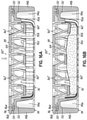
FIG. 16A is a cross sectional view (taken along line 16-16 of FIG. 15) of the integrated cassette and frame structure from FIG. 15, but illustrating the lid in a closed position.
FIG. 16B is a cross sectional view similar to FIG. 16A, but illustrating the lid structure engaging a tissue sample within the cassette recess and against the bottom wall.
FIG. 17 is a perspective view of another embodiment illustrating an integrated cassette and frame structure, with the lid portion shown in an open position.
FIG. 18 is a top view illustrating the integrated cassette and frame structure of FIG. 17, again with the lid portion shown in an open position.
FIG. 19A is a cross sectional view taken generally along line 19A-19A of FIG. 18.
FIG. 19B is a cross sectional view similar to FIG. 19A, but illustrating the lid portion in a closed position.
FIG. 19C is a cross sectional view similar to FIG. 19B, but illustrating the lid portion compressed or moved downwardly against a tissue sample within the cassette body, and illustrating the cassette staged downwardly with respect to the frame and into a second position and into a mold.
FIG. 20A is a perspective, enlarged view of the integrated cassette and frame structure of FIG. 17, and illustrating additional details.
FIG. 20B is a perspective view similar to FIG. 20A, but illustrating the lid portion in a closed position.
FIG. 20C is a perspective view similar to FIG. 20B, but illustrating the cassette staged or moved downwardly with respect to the frame into a second, staged position.
FIG. 21 is a top view of another embodiment illustrating an assembly comprised of an integrated cassette and frame structure.
FIG. 22A is a partially fragmented cross sectional view of the structure shown in FIG. 21.
FIG. 22B is a cross sectioned view of the structure shown in FIG. 22A, but illustrating the lid in a closed position.
FIG. 22C is a perspective view similar to FIG. 22B, but illustrating the cassette staged to a second position within the frame.
FIGS. 23A and 23B respectively show alternative embodiments of the resilient tissue engaging structure, or fingers, used for holding tissue against a bottom wall of the cassette.
FIG. 24A is a cross sectional view of the structure shown with the cassette in the process of being moved or staged between the first and second positions, with the cross section taken transverse to a lengthwise dimension of the frame and cassette.
FIG. 24B is a cross sectional view similar to FIG. 24A, but illustrating the cassette staged completely into the second position.
FIG. 25 is a perspective view of another embodiment illustrating an assembly or apparatus comprised of an integrated cassette and frame structure.
FIG. 26 is a top view of the assembly shown in FIG. 25.
FIG. 27A is an enlarged view of encircled portion “27A” shown in FIG. 26.
FIG. 27B is an enlarged view of the encircled portion “27A” but illustrating the connecting bridge or structure in a biased or second position.
FIG. 28A is a cross sectional view taken along line 28-28 of FIG. 26.
FIG. 28B is a side cross sectional view similar to FIG. 28A, but illustrating the lid in a closed position.
FIG. 29A is a partially sectioned, perspective view of the device shown in FIG. 25, with the lid in the open position.
FIG. 29B is a sectioned, perspective view similar to FIG. 29A, but showing the lid in a closed position.
FIG. 29C is a sectioned, perspective view similar to FIG. 29B but showing the cassette and its lid in a second, staged position relative to the frame.
FIG. 30 is a perspective view illustrating a magazine or holder for a stack of the integrated cassette and frame structures shown in FIG. 25.
FIG. 31A is an enlarged perspective view of the unloading end of the magazine shown in FIG. 30.
FIG. 31B is an enlarged perspective view similar to FIG. 31A, but illustrating the integrated cassette and frame structures respectively being unloaded from the magazine.
DETAILED DESCRIPTION
Referring first to FIGS. 1 and 2, an assembly 10 constructed in accordance with an illustrative embodiment of the invention is shown. Assembly 10 includes a tissue sample cassette 12 carried within a frame 14, which includes a peripheral portion 16. A lid 18 is separably coupled to peripheral portion 16. Peripheral portion 16 generally includes an interior defined between surrounding walls 16 a, 16 b, 16 c, 16 d, and lid 18 is sized and configured to fit in the interior and is separably coupled to at least one of the surrounding walls 16 a, 16 b, 16 c, 16 d. The frame 14 generally includes an interior defined between surrounding outer walls 14 a, 14 b, 14 c, 14 d and the cassette 12 is sized and configured to frictionally or “snap” fit and move within the interior between at least first and second positions, again, as generally discussed in the above-incorporated patent properties and for the same purposes. The first position is shown in FIG. 3B, while the second, “staged” position is shown in FIG. 3C in which the lower portion of the cassette 12 is exposed below the bottom of the frame 14 for allowing cassette 12 and embedded tissue sample to be sectioned in a microtome while the frame 14 is held in the microtome chuck.
The connection of the tissue cassette 12 to the frame 14 may be accomplished in many different manners, such as any of the manners described in the above-incorporated patent properties. Alternatively, the cassette 12 may be coupled to the frame in other novel manners such as described hereinbelow. In the illustrative embodiment, cassette 12 includes cassette retention tabs 20 that are frictionally secured in retention slots 40 of frame 14. The friction fit between the tabs 20 and the slots 40 prevents unwanted movement of the cassette 12 between the first and second positions. Slots 40 are tapered such that slots 40 are narrower at the bottom than at the top. In this regard, the force required to move the cassette retention tabs 20 to the second position is less than the force required to move the tabs 20 to the first position. It will be appreciated that cassette 12 may be configured in any suitable manner as a tissue support and frame 14 may be configured in any suitable manner. Any of the configurations, features, characteristics and materials disclosed for the tissue supports (e.g., cassettes) and frames in the above-incorporated patent properties may be employed for cassette 12 and frame 14. In the embodiment shown, cassette 12 is porous and is releasably retained in frame 14 and frame 14 is further configured to be releasably secured within a microtome chuck (shown in FIG. 4). The general procedure for processing, embedding, and sectioning is discussed in the above-incorporated patent properties in more detail.
Now referring to FIGS. 2 and 3A, the connections between frame 14, peripheral portion 16, and lid 18 are shown in more detail. Peripheral portion 16 is coupled to wall 14 a of frame 14 by a frangible hinge 22. Peripheral portion 16 snap fits into a closed position through the engagement of latches 24, 26, 28 with frame 14 as shown in FIG. 3B. Latches 24, 26 are positioned on outer wall 16 a of peripheral portion 16 and engage with openings 30, 32 in wall 14 a of frame 14 respectively. Latch 28 is positioned on wall 16 c of peripheral portion 16 and engages with an outer flange 34 of wall 14 c of frame 14. Lid 18 is separably coupled to peripheral frame portion 16 through breakaway connections 36 on surrounding walls 16 a, 16 b, 16 c, 16 d. Lid 18 is sized and configured to frictionally or “snap” fit and move within the interior of frame 14 between at least first and second positions, as shown best in FIGS. 3B and 3C. More particularly, lid 18 includes lid retention tabs 38 on each of the four corners of lid 18. Retention tabs 38 are configured to engage with retention slots 40 of frame 14, which are on each of the four corners of frame 14. Lid 18 carries a resilient structure 42 on the central portion of lid 18.
Resilient structure 42 is a compliant structure that holds the tissue in the desired orientation without creating an artifact impression on the tissue sample 44 during processing. As shown in FIG. 3A, one or more tissue samples 44 may be placed in cassette 12 that defines a recess or interior area surrounded by at least one sidewall 12 a and including a bottom wall 12 b. Although a rectangular recess is shown, it will be appreciated that any other shape, such as cylindrical or circular shapes or shapes with troughs or alignment features for the tissue sample 44, may be used instead.
The porosity of resilient structure 42 allows infiltration of the solvents and chemicals used to fix, process, and stain tissue, and of embedding material used to embed the tissue while the tissue is retained by resilient structure 42. Resilient structure 42 has a thickness that is compressible and configured to engage and retain tissue in place during processing and embedding. Further, resilient structure 42 is capable of successful sectioning in the microtome after having its interstices or pores filled with liquefied embedding material which subsequently hardens. Resilient structure 42 may, for example, be an open cell foam material, such as a foam including at least one of a polyether or a polyurethane and which may be a fully reticulated open cell foam. Here, “fully reticulated” means that at least substantially all cells of the foam are open. The open cells help ensure full infiltration and eventual draining of the fluids used during processing and embedding procedures. Resilient structure 42 may further be a gel, sectionable plastic, polyesters, alginates, or other materials that may be infiltrated with the embedding material and successfully sectioned in a microtome without adverse effects on the resulting ribbon of tissue and embedding material.
With reference now to FIG. 3B, assembly 10 is shown with peripheral portion 16 in the closed position and where cassette 12 and lid 18 are in a first position. Once the tissue is loaded in the interior or recess of cassette 12, peripheral portion 16 may be rotated to the closed position. As peripheral portion 16 is moved from the open position to the closed position, frangible hinge 22 severs. Once hinge 22 is severed, peripheral portion 16 may continue to rotate until latches 24, 26, 28 engage with openings 30, 32 and outer flange 34 of frame 14, securely locking peripheral portion 16 to frame 14. With peripheral portion 16 in the closed position, resilient structure 42 biases the tissue sample 44 towards bottom wall 12 b of cassette 12. With peripheral portion 16 securely closed on frame 14, cassette 12 is trapped inside retention slots 40 and cannot become dislodged from frame 14. Lid retention tabs 38 are in alignment with the wider top portion of retention slots 40 of frame 14. Alternatively, in this position, lid retention tabs 38 may be located within a top portion of retention slots 40 and align with corresponding cassette retention tabs 20 when the lid 18 is closed.
As further shown in FIG. 3B, when lid 18 is closed, the resilient structure 42 presses against tissue sample 44 and deforms three dimensionally around tissue sample 44 creating three dimensional spaces around tissue sample 44 and essentially immobilizing tissue sample 44 during the tissue processing and embedding procedures. This also ensures that the tissue sample 44 is held flat against bottom wall 12 b of cassette 12 such that when microtome slices are made, complete and continuous sections of tissue sample 44 may be formed generally as shown in FIG. 5. Once all of sample 44 has been sliced, the next slice would contain only resilient structure 42 and paraffin wax 50, as shown in FIG. 6. One specific type of foam structure suitable for the resilient structure 42 has a pore size of 50-60 ppi (pores per inch), with each pore having a diameter of between about 0.017 inch and 0.20 inch. The foam structure is fully reticulated with a compression force deflection at 20% deflection of 0.55 lbs/in2 and a density of 1.4 lbs/ft3. The foam material may be obtained from Crest Foam of Moonachie, N.J. under the name T-50. This is a polyether/polyurethane foam and operates well with a thickness of 0.06 inch to 0.10 inch with a 0.075 inch thickness being a practical manufacturing example. The foam should be constructed so as to shed or release processing fluid after each reagent cycle of a tissue processing machine. If the foam is too dense or too thick, or not fully reticulated, the reagents can become cross contaminated or the tissue may not be fully infiltrated with the fluids because each fluid bath must fully clear and exchange from one fluid bath to the next.
Now referring to FIGS. 3C and 3D, assembly 10 is shown in which cassette 12 and lid 18 are in the second position. Pressing the center of lid 18 causes breakaway connections 36 to separate, allowing lid 18 to move from the first position (FIG. 3B) towards the second position (FIG. 3C). When connections 36 are broken, continued pressure on the center of lid 18 causes retention tabs 38 to bear against tabs 20 and slide through retention slots 40 of frame 14. Downward movement of lid 18 and tabs 20, 38 causes tissue cassette 12 to move from the first position towards the second position. More particularly, because cassette retention tabs 20 and lid retention tabs 38 are aligned in slots 40, downward movement of lid retention tabs 38 causes downward movement of cassette retention tabs 20. Because slots 40 are tapered, the friction fit between slots 40 and tabs 20, 38 in the second position secures cassette 12 in the second position during the embedding and sectioning process. As best shown in FIGS. 3B and 3C, retention slots 40 include a bottom edge 46. When cassette 12 reaches the second position, edge 46 will prevent further movement of cassette retention tabs 20, and thus lid retention tabs 38, through slots 40. In the second position, tissue sample 44, a portion of cassette 12, and a portion of resilient structure 42 are staged to be sectioned in a microtome. While cassette 12 is shown to have a rectangular configuration, it will be recognized that cassette 12 may have alternative configurations. For example, a cassette may have a circular configuration. Because edge 46 limits the travel of cassette 12 into the second position, edge 46 assures that cassette 12 is staged to a predetermined depth independent of the configuration of cassette 12. The illustrated configuration of cassette 12, frame 14, and lid 18 is an improvement over current assemblies that require a complex lid adjustment procedure whereby the user must choose from a limited number of specific engagement distances between the lid and the cassette. The specific engagement distances were determined by preset tabs in the interior of the cassette basket that engaged and retained the lid. By utilizing a breakaway, rigid central staging lid coupled to a resilient structure according to an option or aspect of the present invention, the complex adjustment procedure for the lid is eliminated. It will be appreciated that other configurations and designs may be used to achieve similar purposes.
Because there are millions of procedures completed each year utilizing assemblies like these, embodiments of the present invention are designed for high production volumes and, consequently, are directed towards use in automated histopathology processes. One such process is automated embedding. An exemplary automated embedding machine (not shown) uses a motorized staging device 48 that pushes the cassette through the frame into the embedding mold 52, which is shown in FIGS. 3B and 3C. A staging device 48 may incorporate spring-loaded cylindrical fingers or feet which push the cassette through frame. The staging device 48 may be improved so that it is capable of cleanly severing breakaway connections 36 between peripheral portion 16 and lid 18 during the staging process. For example, tubular cutters may be axially positioned around the cylindrical fingers that align with connections 36 to cut them, which would be easier than breaking the connections 36 with shear forces alone.
In use, one or more tissue samples 44 are placed within the interior space or recess and, specifically, on bottom wall 12 b of cassette 12 as shown in FIG. 3A. Tissue sample 44 is sized and oriented in cassette 12 according to the required section plane desired by the pathologist for each tissue sample 44. Peripheral portion 16 is then closed and snapped into place such that resilient structure 42 (e.g., foam) bears against and traps tissue sample 44 against bottom wall 12 b in the desired orientation as shown in FIG. 3B. Resilient structure 42 may deform to create a three dimensional space that receives tissue sample 44. The force of resilient structure 42 against tissue sample 44 should be enough to immobilize tissue sample 44 but not enough to induce artifacts in tissue sample 44. At this point, assembly 10 with the trapped tissue sample 44 may be subjected to a conventional tissue processing operation that uses vacuum, heat and chemicals to remove the interstitial fluids within the tissue and replace those fluids with a hardenable material, such as molten paraffin. As mentioned above, during these processing steps, the porous nature of the foam or other resilient structure 42 allows the fluids to reach and fully infiltrate into tissue sample 44. In addition, resilient structure 42 traps tissue sample 44 flat against bottom wall 12 b without leaving artifacts or markings on the tissue that might interfere with subsequent analysis under a microscope. It will be appreciated that different types of resilient cellular materials may be chosen based, for example, on the type of tissue to be processed and analyzed. For example, small mucosal tissue samples may be held and processed with success using the T-50 foam discussed above, while other types of tissue, such as fatty tissue, may be better served by another type of resilient cellular material. As another example, larger tissue samples may require retention structure that operates well over a large surface area.
It will also be appreciated that the processing steps may take place before assembling tissue cassette 12 with frame 14. After the tissue processing is complete, lid 18 may be separated from peripheral portion 16 whereby cassette 12 may be moved to a second position as shown in FIG. 3C exposing a portion of cassette 12 below the bottom edge 46 of frame 14. Cassette 12 and frame 14 are then placed into a suitable mold 52 and embedded in paraffin 50. Cassette 12 and/or frame 14 may include machine-readable indicia allowing a machine to determine the type and size cassette 12 being used and to make an appropriate decision as to which mold to place the cassette 12 in for embedding. As shown in FIG. 3D, the entire assembly 10 including the exposed portion of cassette 12 is embedded within a hardened block of paraffin wax 50. The mold 52 may generally follow the contour of the bottom 12 b of cassette 12, although the portion of the mold surrounding cassette 12 is preferably square as opposed to round. This assists with the subsequent production of ribbon slices, as shown in FIG. 4. This portion of the procedure may therefore be similar to that disclosed in the above-incorporated patent properties. As discussed therein, and with reference to FIG. 4, frame 14 is then used as a fixture for mounting the embedded assembly 10 in a microtome 54. The necessary number of slices 56 are taken of the exposed underside until enough sections or slices 56, similar to those shown in FIG. 5, are taken and appropriately mounted on a microscope slide, stained and cover slipped.
Another method (not shown) of loading tissue sample 44 in assembly 10 is possible. First, peripheral portion 16 is detached from frame 14, which is set aside. Tissue sample 44 is placed onto resilient structure 42, and then frame 14 is installed on top of lid 18. When frame 14 is installed on top of peripheral portion 16, latches 24, 26, 28 of peripheral portion 16 engage with openings 30, 32 and flange 34, respectively, of frame 14. In this manner, peripheral portion 16 is secured to frame 14. Assembly 10 may then be positioned in its usual upright position while resilient lid 18 remains coupled to frame 14 and structure 42 secures tissue sample 44 to bottom wall 12 b of cassette 12. This technique can be especially useful for processing an array of small tissue samples because of the easy access to resilient structure 42. In addition, resilient structure 42 may have tissue specific orientation or holding alignment features to facilitate orientation of very specific types of tissue samples. For instance, resilient structure 42 may be made from a gel material having specific cavities or grooves that accept small, hard to orient tissue samples. Such small tissue samples may be, for example, optic nerves from mice or thin arterial structures that must stand up on end perpendicular to the sectioning plane.
Cassette 12 may be formed from a sectionable plastic, such as perfluoroalkoxyethylene (PFA), or polyethylene (PE)-based or containing materials in accordance with the above-incorporated patent properties. The material forming cassette 12 may be at least translucent so as to be non-distracting during tissue analysis. Frame 14, including peripheral portion 16, and lid 18 may be formed from a more rigid, less costly plastic, such as acetal. Acetal is far easier to mold in large quantities or in multi-cavity injection molds. Unlike previous cassettes used during tissue analysis, lid 18 may be formed from a more cost-effective plastic that is different from the plastic used to form cassette 12. For instance, lid 18 may be formed from acetal. In this regard, the volume of FEP/PFA or other sectionable polymer used in the assembly 10 is minimized, which can be beneficial for cost reasons. As will be appreciated from FIG. 2, cassette 12 may be molded separately from the frame 14 and then inserted into the frame 14 with a suitable friction or “snap” fit. Further, when cassette 12 and frame 14 are made of materials with significantly different melting temperatures, they can be co-molded or insert molded in an injection mold machine. In this case, there would be breakaway connections (not shown) similar to the connections 36 formed between the peripheral portion 16 and the lid 18.
Cassette 12 is molded within frame 14 and after frame 14 has been molded. In this case, the frame 14 has a higher melting temperature than the material for forming the cassette 12. The cassette material will not melt the frame material and this process will secure the cassette 12 and frame 14 together in a single unit. In other embodiments, described below, the lid may be formed from the same microtome sectionable material as the cassette. In that way, through robotic assembly, cassette 12 can be molded with frame 14 surrounding it resulting in a processing container that the customer does not need to assemble from parts. Additionally, using such a molding process creates a secure, one piece assembly for shipping and handling. By combining the cassette and frame into a single piece prior to the customer receiving them, the assembly arrives as a single piece ready to load with tissue. This is advantageous over prior assemblies where the user was required to assemble the components before loading the tissue. Further, by surrounding the cassette by a dimensionally stable frame material, the integrity and shape of the cassette are maintained during shipping.
Referring now to FIGS. 7, 8 and 9, an assembly 100 is shown and constructed in accordance with another illustrative embodiment of the invention. Like elements of structure and function in the embodiments to follow are denoted with like reference numerals to those previously shown and described. The assembly 100 includes a tissue sample cassette 112 including a body 112 a with an interior or recess 112 b carried within a frame 114, which includes a peripheral portion 116. A lid 118 is separably coupled to the peripheral portion 116 and the peripheral portion 116 generally includes an interior 116 a defined between surrounding walls 116 b. The lid 118 is sized and configured to fit in the interior 116 a and is separably coupled to at least one of the surrounding walls 116 b. The frame 114 generally includes an interior 114 a defined between surrounding outer walls 114 b and the cassette 112 is sized to fit within and, after detachment from the frame 114, move within the interior 114 a of the frame 114 between at least a first position and a second “staged” position, as discussed in the above-incorporated patent properties and for the same purposes.
More specifically, in this embodiment, the entire cassette and frame assembly may be formed in a single molding process from a single material. This material may, for example, be a polyethylene-polypropylene blend or any other suitable material that has sufficient rigidity to provide the necessary support and resist warpage during storage and shipping, but which allows the cassette body 112 a to be microtome sectioned as disclosed in the above-incorporated patent properties. Alternatively, the lid 118, frame 114, cassette 112 and/or portions thereof may be formed from different materials depending on factors such as cost and functionality. Of course, the molding process may have separate molding steps. However, as compared to previous embodiments, a single material embodiment has various advantages, such as cost advantages associated with a simpler molding process, and the use of a single, cost efficient and yet functional material. This embodiment further shows the use of flexible fingers 120 as the resilient, biasing structure extending from an interior surface of the lid 118 for engaging with a tissue sample or samples 112 (FIG. 10A) as will be discussed below. The peripheral frame portion 116 is coupled to the remainder of the frame 114 by a hinge 122. As best shown in FIG. 9, the lid 118 is coupled to the peripheral portion 116 with material “bridges” or breakaway connections 126 that are broken as the user depresses on the lid 118 during the staging process as will be discussed below. The lid 118 further includes “cutters” 130 that align with bridges or breakaway connections 132 that secure the cassette body 112 a to the frame 114 as also shown in FIG. 9. As the user depresses the lid 118 and breaks the lid 118 away from the peripheral portion 116 at connections 126, these cutters 130 cut through or break the bridges or connections 132 that retain the cassette body 112 a to the frame 114. It will be appreciated that the cutters 130 do not need to be sharp, but are at least meant to concentrate force on the thin connections 132. FIGS. 10A and 10B illustrate the respective open and closed positions of the cassette lid 118 and peripheral portion 116. FIG. 10B illustrates the resilient fingers 120 used to retain a tissue sample(s) 124 against the bottom wall 112 c of the cassette 112. FIG. 10C illustrates the staging movement of the cassette 112 between the upper or first position (not shown) and the lower or second position that is within a mold 140.
In FIG. 10C, the bridges or connections 126 previously discussed have been broken and, thus, the lid 118 is retained against the upper peripheral surface of the cassette body 112 a. In the second position, or lower position, the cassette body 112 a is exposed below the bottom of the frame 114 for allowing the cassette body 112 a and the tissue sample 124 to be sectioned in a microtome 54 (FIG. 4) after embedding and while the frame 114 is held in the microtome chuck, as previously described. As further shown in FIG. 10C, the frame 114 is frictionally held within the mold 140 by being retained against a resilient seal member 142 coupled with the mold 140. FIG. 10D illustrates the process after the step of filling the mold 140 with an embedding material, such as paraffin 150, and allowing the paraffin 150 to solidify into a block that encases both the sectionable cassette 112 and the tissue sample 124 held within the cassette recess or interior 112 b. As fully described in the above-incorporated patent properties, and above, this solidified block 150 is then sectioned in a microtome 140 (FIG. 4) and the thin, ribbon-like sections 56 are placed on microscope slides (not shown) for pathological diagnoses.
FIGS. 11A, 11B and 11C better illustrate the construction and use of the breakaway connections 126, 132 and cutters 130 that are associated with the cassette 112 and the frame 114. Specifically, the cutters 130 align with the bridges 132 that connect the cassette body 112 a to the frame 114 and, as shown in FIG. 11B, these cutters 130 when depressed downwardly will cut through or help break or shear the frangible bridges or connections 132 thereby separating the cassette 112 from the frame 114. At about the same time, the frangible bridges of material 126 that hold the cassette lid 118 to the peripheral frame portion 116 break and the lid 118 then travels with the cassette body 112 a from the first position (not shown) to the second, staged position, illustrated in FIG. 11C. FIGS. 12A and 12B illustrate another perspective showing the bridges 132 and the use of the cutters 130 to break the bridges 132 and allow movement of the cassette 112 and the cassette lid 118 from the first position shown in FIG. 12A to the second position shown in FIG. 12B.
FIGS. 13 and 14 illustrate another illustrative embodiment of a device 100′ that is very similar to the embodiment shown and described with respect to FIG. 7 through FIGS. 12A and 12B. Like reference numerals in FIGS. 13 and 14 refer to like structure shown and described above. Therefore, further explanation of previously described structure and function or methodology is not necessary. In this embodiment, the resilient fingers 120 depicted in the previous embodiment have been replaced by pads 160 that are coupled to an underside of the lid 118 by resilient legs 162. Again, this entire cassette and frame structure, including the pad members 160 and legs 162 may be molded out of a single material and within a single mold, thereby greatly simplifying the manufacturing process. Alternatively, two or more of these components may be co-molded or insert molded such as previously described. As shown in FIG. 14, the resilient pad members 160 are used to retain the tissue sample or samples 124 against the bottom surface 112 c of the cassette 112, thereby holding the tissue sample or samples 124 in a desired orientation and flatly against the inner bottom surface 112 c of the cassette interior 112 b. The legs 162 that connect the pads 160 to the underside of the cassette lid 118 may slightly rotate and bend as the pads 160 engage the tissue sample 124 when the lid 118 is closed. This stabilizes and holds the tissue sample(s) 124 during tissue processing and embedding.
FIGS. 15, 16A and 16B illustrate yet another illustrative embodiment of a device 100″ that is very similar to the embodiment of FIGS. 13 and 14. Like reference numerals again refer to like elements of structure and function as previously described and, therefore, need not be described again. In this embodiment, the only difference relative to the embodiment in FIGS. 13 and 14 is that the resilient pad members 160′ have been changed in shape and slightly in structure to be more rounded and for the leg members 162′ to be resilient and twistable similar to springs to better engage and hold one or more tissue samples 124 within the cassette interior 112 b and against the interior bottom surface 112 c of the cassette 112 as shown in FIG. 16B.
Now referring to FIGS. 17, 18, 19A and 19B, another illustrative embodiment of a device 100″′ is shown and again may be formed from a single material and within a single mold, as will be appreciated from the description to follow. Again, like reference numerals in this embodiment refer to like elements of previous embodiments. In this embodiment, like the embodiment shown and described with regard to FIG. 7 through FIG. 12B, the cassette body 112 a is connected to the interior peripheral surfaces of the frame 114 by breakaway material bridges or connections 132. The lid 118′ of the cassette 112, however, is designed to fit and latch within the cassette body 112 a and to be depressed downwardly into the interior 112 b of the cassette body 112 a and directly or indirectly against one or more tissue samples 124 therein to retain the tissue sample or samples 124 against the interior bottom surface 112 c of the sectionable cassette 112. The “latching” may simply be a friction fit. The material bridges 132 between the cassette body 112 a and the frame 114 are designed to be thin and easily frangible as the cassette 112 is staged from the first position to the second position, shown in FIG. 19C. A user or a machine may depress the cassette lid 118′ into the cassette body 112 a as also shown in FIG. 19C and the cassette lid 118′ may snap between two detents 170, 172 as also shown in FIG. 19C. A hinge 176 connects the lid 118′ to the frame 114 and has a length such that the cassette lid 118′ may extend downwardly into the cassette body 112 a as the cassette body 112 a is staged from the first position shown in FIG. 19B to the second position shown in FIG. 19C. The structure and function of this illustrative flexible and elongated hinge structure 176 is shown better in FIGS. 20A, 20B and 20C.
FIGS. 21 through 24B illustrate yet another embodiment of a device 200. Again, this device 200 may be formed from a single material and within a single mold, as will be appreciated from figures and the description to follow, or as in any of the described embodiments, may be formed from different materials using other molding techniques such as co-molding or overmolding or insert-molding. Again, like reference numerals in this embodiment refer to like elements of structure and corresponding function as described with regard to previous embodiments. Therefore, further description of such elements is not repeated here. Elements having one or more prime (′) marks are slightly modified from prior, corresponding elements, as will be described and/or readily apparent from the drawings. In this embodiment, like the embodiments previously shown and described, the cassette body 112 a is connected to the interior peripheral surfaces of the frame 114 by breakaway material bridges or connections 132. The lid 118″ of the cassette 112 is designed to latch to the cassette body 112 a using a plurality of latches 202 as shown best in FIGS. 24A & 24B. The lid 118″ further includes cutters 130 for previously described reasons. Like previous embodiments, the lid 118″ is separable from the peripheral portion 116 of the frame 114. Another difference between this embodiment and previously described embodiments having “resilient structure” for engaging tissue samples within the cassette 112, is that the resilient structure comprises a plurality of linear fingers 204 which may be straight and distally tapered as shown best in FIG. 23A. As alternatively shown in FIG. 23B, the distal ends 204 a of the fingers 204 may instead be curved to provide more surface area engagement with one or more tissue samples and a “softer” engagement that is less likely to damage the tissue sample. Another difference between this embodiment and previously described embodiments relates to the method and structure for positioning the cassette 112 and lid 118″ within the frame 114. In this regard, as best shown in FIGS. 24A and 24B, each corner of the cassette lid 118″ engages with a cassette positioning element 210 that is formed as part of the interior corner of the frame 114. The cassette positioning elements 210 are flexible and hollow such that as the corners of the lid 118″ pass by the cassette positioning elements 210 they deform the cassette positioning elements 210 and ultimately “snap” below the cassette positioning elements 210 as shown, for example, in FIGS. 22B and 24B. This retains the cassette 112 and lid 118″ in the second position, and ready for embedding and subsequent microtome sectioning, as previously described.
FIGS. 25 through 29C illustrate yet another embodiment of a device 200′ similar, for example, to the device 200 shown and described with respect to FIGS. 21 through 24B. While this device 200′ may be formed from a single material and also within a single mold, various features have been included so as to make this device more easily and readily molded from at least two different materials for the reasons discussed below. Again, like reference numerals in this embodiment refer to like elements of structure and corresponding function as described with regard to previous embodiments. Therefore, for the sake of brevity further description of such elements and/or methodology is not repeated here. Elements have one or more prime (′) marks are slightly modified from prior, corresponding elements, as will either be described or readily apparent from the illustrations. In this embodiment, like the embodiments previously shown and described, the cassette body 112 a is connected to the interior peripheral surfaces of the frame 114 by breakaway material bridges or connections 132′. The lid 118″ of the cassette 112 includes cutters 130 for the same reasons as previously described. The lid 118″ is also designed to latch to the cassette body 112 a using undercuts 203 a that engage and latch with hook-like members 203 b on opposite, inner sides of the cassette body 112 a. Like previous embodiments, the lid 118″ is separable from the peripheral portion 116 of the frame 114. This embodiment also includes resilient structure carried on the underside of the lid 118″. The resilient structure is in the form of curved, resilient fingers 204′ for purposes of allowing flexible engagement between distal ends 204 a′ of the fingers 204′ and the one or more tissue samples 124 in the cassette body 112 a. Another difference between this embodiment and the embodiment of FIG. 21 is in the structure for positioning the cassette 112 and lid 118″ within the frame 114. In this regard, each corner of the cassette lid 118″ engages with a cassette positioning element 210′ that is formed as part of the interior corner of the frame 114. As with the previously described embodiment, there is one cassette positioning element 210′ formed as part of each of the four interior corners of the frame 114. To provide further flexibility as the cassette 112 is moved from the first position shown in FIGS. 29A and 29B to the second position shown in FIG. 29C, a central slot 210 a is formed in each of these positioning elements 210′. In a manner similar to that shown and described with regard to FIGS. 21 through 24B, the cassette positioning elements 210′ are flexible and hollow such that as the corners of the lid 118″ pass by the cassette positioning elements 210′ they deform the cassette positioning elements 210′ and ultimately “snap” below the cassette positioning elements 210′ as shown, for example, in FIG. 29C. This retains the cassette 112 and lid 118″ in the second position, and ready for embedding and subsequent microtome sectioning, as previously described.
As previously mentioned, the embodiment of FIGS. 25 through 29C is especially adapted to allow the use of first and second different, moldable materials. More particularly, the material used for the cassette body 112 a and the lid 118″ is preferably a material that is sectionable in a microtome and has the other various qualities and characteristics as discussed above. As disclosed above and in the incorporated patent properties, this material may be FEP/PFA, polyethylene (PE) based materials, or any other suitable polymeric or other moldable material. The material used for the frame 114 and the peripheral frame portion 116 is a different material, such as acetal, and has a higher melting temperature than the material used for the cassette body 112 a and the lid 118″. The frame 114 and its peripheral frame portion 116 are also formed from a higher modulus, stiffer material than the material of the cassette body 112 a and the lid 118″. Among the advantages to this aspect is that the frame 114 has the rigidity needed to be held securely in a microtome chuck during the sectioning procedure described above. The use of different materials, having different thermal and other properties, such as melting temperature and fluid absorption characteristics, presents certain challenges during the molding process, as well as during the histopathologic process used when preparing tissue samples as generally described above. For example, the molding process will inevitably result in the molding material shrinking as the material cools. The use of different materials, such as polyethylene (PE) and acetal, will therefore generally result in different shrinkage rates and/or shrinkage amounts between the components formed of these different materials. During the histopathologic process, the use of processing fluids, such as reagents, will result in swelling of polymeric materials such as PE materials used for the microtome sectionable cassette body 112 a and lid 118″. The components formed from PE or similar material will therefore swell more than the surrounding components including the frame 114 and the peripheral frame portion 116, which are formed from acetal or similar material. These shrinking and swelling actions can result in undesirable distortions and warpage between the different components formed from different materials. This has been a significant challenge in past development of microtome sectionable histologic biopsy sample cassettes. For example, a microtome sectionable cassette formed of PE would swell and warp to an unacceptable extent within the stiffer, acetal cassette during tissue processing in a liquid reagent bath. Therefore, much more expensive materials such as PFA were used instead because they would not swell to such a great extent.
To accommodate and prevent such movements or distortions between the components formed of different materials, especially PE and acetal, a special bridge construction 132′ is used, such as shown in FIGS. 27A and 27B. In this embodiment, undesirable distortions and warpage is prevented between the peripheral frame portion 116 and the attached (integrally molded) lid 118″, and also between the frame 114 and the attached (integrally molded) cassette body 112 a. In this construction, the bridge 132′ is formed with a “T” shape such that the cross member 132 a′ of the “T” is used as an anchor in the frame 114 constructed of a first material (such as acetal) and the straight portion 132 b′ of the “T” is molded and connects with the other component, in this case the cassette body 112 a formed of a second, different material (such as PE). The bridge 132′ is molded with the cassette body 112 a and is therefore also formed from the second material (e.g., PE). The cassette body 112 a further includes an opening 220 toward which the T-shaped bridge member 132′ may be biased or moved during relative movement between the cassette body 112 a and the frame 114. In this manner, the relative movement is accommodated without causing warpage or other undesirable distortions between the cassette body 112 a and the frame 114 either during molding of the device 200′ or as a result of its subsequent use in a tissue processing operation as described above. It will be appreciated that the breakaway connecting structure 132′ shown in FIGS. 27A and 27B is a connecting structure that will accommodate movement in either direction although the movement is only shown in one direction in FIG. 27B, in order to accommodate and prevent distortions or warpage of the cassette body 112 a in this case relative to the frame 114. It will further be appreciated that the frame 114 and the cassette body 112 a have four such breakable connections or bridges 132′ as generally shown in FIG. 25, and the lid 118″ and peripheral frame portion 116 similarly have four such breakable connections or bridges 132′ as also shown in dashed lines in FIGS. 25 & 26, and more specifically shown in FIG. 29B (only two connections 132′ shown). All eight connections 132′ facilitate not only the breakaway connection features as discussed in regard to other embodiments described herein, but also reduced or minimized distortions/warpage between the peripheral frame portion 116 and lid 118″, and also between the frame 114 and cassette body 112 a. The respective cassette body 112 a, lid 118″ and all eight bridges or connectors 132′ are molded from the second, relatively low melting temperature material, while the frame 114 and peripheral frame portion 116 are molded from the first material which has a higher melting temperature than the second material. The respective cassette body 112 a and lid 118″ are constructed with outer dimensions sufficiently smaller than the interior dimensions of the respective frame 114 and frame portion 116 to accommodate movement such as shrinking or swelling and, in particular, swelling of the interior component. The cassette body 112 a and the lid 118″ will not contact the surrounding component, i.e., the frame 114 or the peripheral frame portion 116, due to swelling of the cassette body 112 a or lid 118″.
FIGS. 30, 31A and 31B illustrate a magazine 230 for holding and dispensing integrated cassette and frame structures or assemblies, such as the device 200′ described immediately above with respect to FIGS. 25 through 29C. Because the two-material molded device 200′ is formed with a relatively rigid and planar structure in which the lid 118″ is held in an open position relative to the frame 114 by a relatively stiff frangible hinge structure 22′, the devices 200′ may be readily stacked as shown in FIG. 30 and stored, transported, and ultimately dispensed from the magazine 230 as shown. Each device 200′ will be self-supporting in the configuration shown with the frame portion 116 and lid 118″ held generally horizontal with the frame 114. The stack of devices 200′ will typically be vertically oriented, as shown in FIG. 30, and will gravity feed to a lower output slot 232 of the magazine such that the devices 200′ may be dispensed from either side of the magazine 230 by being pushed out of the magazine output slot 232 in either direction, as illustrated. This is helpful because the first step in a typical histopathologic process or operation is to print an accession number or tracking number on the frame 114 of the device 200′. This will be accomplished by printing the number on the angled front face 234 of each frame 114 or on a label (not shown) applied to the front face 234. Therefore, the device 200′ readily lends itself to automated dispensing from the magazine 230 to a printer (not shown) for the printing operation. Subsequently, the device 200′ may be used as generally described above.
While the present invention has been illustrated by the description of specific embodiments thereof, and while the embodiments have been described in considerable detail, it is not intended to restrict or in any way limit the scope of the appended claims to such detail. The various features discussed herein may be used alone or in any combination within and between the various embodiments. Additional advantages and modifications will readily appear to those skilled in the art. The invention in its broader aspects is therefore not limited to the specific details, representative apparatus and methods and illustrative examples shown and described. Accordingly, departures may be made from such details without departing from the scope or spirit of the general inventive concept.

Claims (17)

What is claimed is:
1. A histologic tissue sample support device comprising:
a tissue cassette having a recess including at least one side wall and a bottom wall, the tissue cassette formed of material that can be successfully sectioned in a microtome and is resistant to degradation from solvents and chemicals used to fix, process and stain tissue;
a frame including a bottom edge, the tissue cassette being movably coupled to the frame; and
a lid coupled to the frame;
wherein the lid and the tissue cassette are capable of moving from a first position to a second position with respect to the frame, and in the second position the bottom wall and at least a portion of the side wall extend beyond the bottom edge of the frame for sectioning in the microtome.
2. The support device of claim 1, wherein the lid is coupled to the frame with at least one breakaway connection.
3. The support device of claim 2, wherein the breakaway connection accommodates movement of the lid with respect to the frame without causing warpage or undesirable distortions of the lid or the frame.
4. The support device of claim 1, wherein the cassette is coupled to the frame with at least one breakaway connection.
5. The support device of claim 4, wherein the breakaway connection accommodates movement of the cassette with respect to the frame without causing warpage or undesirable distortions of the cassette or the frame.
6. The support device of claim 4, wherein the lid further includes a cutter to break the breakaway connection.
7. The support device of claim 1, wherein the cassette, lid and frame are molded from a single material.
8. The support device of claim 7, wherein the lid is coupled to the resilient structure.
9. The support device of claim 1, wherein the cassette and frame are co-molded or insert molded from different materials.
10. The support device of claim 1, further comprising:
a microtome sectionable, resilient structure being configured to engage and retain tissue in place within the recess during processing and embedding;
and wherein the lid is used to compress the resilient structure against the tissue, and the resilient structure is further capable of successful sectioning in the microtome and allows infiltration of the solvents and chemicals used to fix, process and stain tissue, and of embedding material used to embed the tissue while the tissue is retained by the resilient structure in the recess.
11. The support device of claim 1, wherein:
the tissue cassette is formed of a first material that can be successfully sectioned in a microtome, and is resistant to degradation from solvents and chemicals used to fix and process the tissue sample during a histologic procedure; and
the frame is formed from a second material different from the first material and being formed integrally with the tissue cassette.
12. The support device of claim 11, wherein:
the lid is formed from the first material.
13. The support device of claim 12, further comprising:
a peripheral portion of the frame surrounding the lid, wherein the peripheral portion is formed from the second material.
14. The support device of claim 1, wherein:
the frame further includes a peripheral portion and the lid is separably coupled to the peripheral portion, and
the lid is separated from the peripheral portion when the lid and the tissue cassette are moved from the first position to the second position.
15. The support device of claim 1, wherein the lid is coupled to the peripheral portion by a hinge allowing the lid to pivot relative to the peripheral portion between open and closed positions.
16. The support device of claim 15, wherein the hinge is frangible.
17. The support device of claim 15, wherein the hinge is flexible and elongates as the lid and tissue cassette move from the first position to the second position.
US15/886,917 2015-08-04 2018-02-02 Sectionable cassette and embedding frame with tissue immobilizing separable lid, and methods for preparing biopsy tissue samples Active 2039-02-27 US11226272B2 (en)

Priority Applications (3)

Application Number Priority Date Filing Date Title
US15/886,917 US11226272B2 (en) 2015-08-04 2018-02-02 Sectionable cassette and embedding frame with tissue immobilizing separable lid, and methods for preparing biopsy tissue samples
US17/544,247 US11774330B2 (en) 2015-08-04 2021-12-07 Sectionable cassette and embedding frame with tissue immobilizing separable lid, and methods for preparing biopsy tissue samples
US18/229,754 US20230375444A1 (en) 2015-08-04 2023-08-03 Sectionable cassette and embedding frame with tissue immobilizing separable lid, and methods for preparing biopsy tissue samples

Applications Claiming Priority (4)

Application Number Priority Date Filing Date Title
US201562200753P 2015-08-04 2015-08-04
US201662356170P 2016-06-29 2016-06-29
PCT/US2016/044379 WO2017023666A1 (en) 2015-08-04 2016-07-28 Sectionable cassette and embedding frame with tissue immobilizing separable lid, and methods for preparing biopsy tissue samples
US15/886,917 US11226272B2 (en) 2015-08-04 2018-02-02 Sectionable cassette and embedding frame with tissue immobilizing separable lid, and methods for preparing biopsy tissue samples

Related Parent Applications (1)

Application Number Title Priority Date Filing Date
PCT/US2016/044379 Continuation-In-Part WO2017023666A1 (en) 2015-08-04 2016-07-28 Sectionable cassette and embedding frame with tissue immobilizing separable lid, and methods for preparing biopsy tissue samples

Related Child Applications (1)

Application Number Title Priority Date Filing Date
US17/544,247 Division US11774330B2 (en) 2015-08-04 2021-12-07 Sectionable cassette and embedding frame with tissue immobilizing separable lid, and methods for preparing biopsy tissue samples

Publications (2)

Publication Number Publication Date
US20180156701A1 US20180156701A1 (en) 2018-06-07
US11226272B2 true US11226272B2 (en) 2022-01-18

Family

ID=57943662

Family Applications (3)

Application Number Title Priority Date Filing Date
US15/886,917 Active 2039-02-27 US11226272B2 (en) 2015-08-04 2018-02-02 Sectionable cassette and embedding frame with tissue immobilizing separable lid, and methods for preparing biopsy tissue samples
US17/544,247 Active US11774330B2 (en) 2015-08-04 2021-12-07 Sectionable cassette and embedding frame with tissue immobilizing separable lid, and methods for preparing biopsy tissue samples
US18/229,754 Pending US20230375444A1 (en) 2015-08-04 2023-08-03 Sectionable cassette and embedding frame with tissue immobilizing separable lid, and methods for preparing biopsy tissue samples

Family Applications After (2)

Application Number Title Priority Date Filing Date
US17/544,247 Active US11774330B2 (en) 2015-08-04 2021-12-07 Sectionable cassette and embedding frame with tissue immobilizing separable lid, and methods for preparing biopsy tissue samples
US18/229,754 Pending US20230375444A1 (en) 2015-08-04 2023-08-03 Sectionable cassette and embedding frame with tissue immobilizing separable lid, and methods for preparing biopsy tissue samples

Country Status (8)

Country Link
US (3) US11226272B2 (en)
EP (2) EP4273531A3 (en)
JP (2) JP6953395B2 (en)
CN (1) CN108351283A (en)
AU (3) AU2016302744B2 (en)
CA (1) CA2994393A1 (en)
DK (1) DK3335025T3 (en)
WO (1) WO2017023666A1 (en)

Families Citing this family (16)

* Cited by examiner, † Cited by third party
Publication number Priority date Publication date Assignee Title
CA2994393A1 (en) 2015-08-04 2017-02-09 Biopath Automation, L.L.C. Sectionable cassette and embedding frame and related methods
US11510660B2 (en) 2018-08-27 2022-11-29 Leica Biosystems Richmond, Inc. Biopsy sample container and method of use
JP7190793B2 (en) * 2019-01-11 2022-12-16 サクラ精機株式会社 tissue processing device
EP3693720B1 (en) * 2019-02-11 2023-01-11 Heraeus Electro-Nite International N.V. Method and apparatus for demolding and analyzing a direct analysis sample
CN109916681A (en) * 2019-03-10 2019-06-21 西安培华学院 A kind of mobile device of digital pathological section
WO2020206545A1 (en) * 2019-04-12 2020-10-15 Ambartsoumian Gourgen Tissue embedding cassette with shield
US11498077B2 (en) 2019-11-12 2022-11-15 Biopath Automation, Llc Sectionable cassette and embedding frame with connectors, and methods for preparing biopsy tissue samples
JP7068382B2 (en) * 2020-05-12 2022-05-16 株式会社Kbbm Biological tissue cutting method, biological tissue cutting device and biological tissue cutting substrate
CN111562165B (en) * 2020-05-25 2022-11-18 西安美佳家医疗科技有限责任公司 Pathological liquid-based thin-layer cell tissue embedding machine and using method thereof
DE102020119764A1 (en) 2020-07-27 2022-01-27 Rheinisch-Westfälische Technische Hochschule Aachen (RWTH), Körperschaft des öffentlichen Rechts Device and method for the preparation and preparation of tissue samples
EP3995163A1 (en) * 2020-11-10 2022-05-11 Fenwal, Inc. Retaining table for fluid processing system
CN113281141A (en) * 2021-05-14 2021-08-20 四川省肿瘤医院 Biopsy sample transfer kit and pathological wax block manufacturing method
USD953562S1 (en) 2021-06-09 2022-05-31 Esah Ali Tissue cassette
CA3222400A1 (en) * 2021-06-18 2022-12-22 Leica Biosystems Nussloch Gmbh Cassette for holding and orienting tissue sample
WO2023220855A1 (en) * 2022-05-16 2023-11-23 Leica Biosystems Nussloch Gmbh Device and method for embedding tissue sample
WO2024013663A1 (en) * 2022-07-11 2024-01-18 Illumisonics Inc. Cartridge for storing tissue for imaging

Citations (12)

* Cited by examiner, † Cited by third party
Publication number Priority date Publication date Assignee Title
US4421246A (en) 1982-06-21 1983-12-20 Allied Corporation Biological tissue cassette
US5127537A (en) 1991-06-05 1992-07-07 Graham Donald R Tissue cassette with a living hinge
US5427742A (en) 1994-04-26 1995-06-27 Holland; Wayne Tissue processing cassette
US20050084425A1 (en) 2002-09-26 2005-04-21 Biopath Automaction, L.L.C. Cassette for handling and holding tissue samples during processing, embedding and microtome procedures, and methods therefor
US20070116612A1 (en) 2005-11-02 2007-05-24 Biopath Automation, L.L.C. Prefix tissue cassette
US20070140920A1 (en) 2005-12-19 2007-06-21 Mccormick James B Histological specimen cassette and associated method of use
US20070166834A1 (en) 1998-10-05 2007-07-19 Biopath Automation, L.L.C. Apparatus and method for harvesting and handling tissue samples for biopsy analysis
US20100184127A1 (en) * 2009-01-22 2010-07-22 Biopath Automation, L.L.C. Microtome sectionable biopsy support for orienting tissue samples
JP2011503519A (en) 2006-12-12 2011-01-27 バイオパス・オートメーション・エル・エル・シー Biopsy support with sectionable elastic foam material
US20130196371A1 (en) 2012-01-26 2013-08-01 Western Michigan University Research Foundation (WMURF) Tissue cassette assembly
CN204855183U (en) 2015-07-24 2015-12-09 南通大学附属医院 Eyeball pathologic sampling mould
US20180156701A1 (en) 2015-08-04 2018-06-07 Biopath Automation, L.L.C. Sectionable cassette and embedding frame with tissue immobilizing separable lid, and methods for preparing biopsy tissue samples

Family Cites Families (8)

* Cited by examiner, † Cited by third party
Publication number Priority date Publication date Assignee Title
JP3049537B2 (en) * 1995-02-03 2000-06-05 悌二 竹崎 Fixation support method for biopsy sample, fixation support agent and embedding cassette
US5817032A (en) 1996-05-14 1998-10-06 Biopath Automation Llc. Means and method for harvesting and handling tissue samples for biopsy analysis
CA2368103C (en) 1998-10-05 2009-05-26 Biopath Automation, L.L.C. Apparatus and method for harvesting and handling tissue samples for biopsy analysis
CA2499369C (en) * 2002-09-26 2010-06-29 Biopath Automation, L.L.C. Cassette and embedding assembly, staging devices, and methods for handling tissue samples
WO2007114958A2 (en) * 2006-04-06 2007-10-11 Hansen John G Specimen retention container
CA2876682A1 (en) * 2012-06-22 2013-12-27 Leica Biosystems Nussloch Gmbh Biopsy tissue sample transport device and method of using thereof
US9389154B2 (en) 2013-03-15 2016-07-12 Leica Biosystems Nussloch Gmbh Tissue cassette with biasing element
CN203908850U (en) * 2014-01-10 2014-10-29 刘勇 Integrated pathological tissue embedding box

Patent Citations (14)

* Cited by examiner, † Cited by third party
Publication number Priority date Publication date Assignee Title
US4421246A (en) 1982-06-21 1983-12-20 Allied Corporation Biological tissue cassette
US5127537A (en) 1991-06-05 1992-07-07 Graham Donald R Tissue cassette with a living hinge
US5427742A (en) 1994-04-26 1995-06-27 Holland; Wayne Tissue processing cassette
US20070166834A1 (en) 1998-10-05 2007-07-19 Biopath Automation, L.L.C. Apparatus and method for harvesting and handling tissue samples for biopsy analysis
US20050084425A1 (en) 2002-09-26 2005-04-21 Biopath Automaction, L.L.C. Cassette for handling and holding tissue samples during processing, embedding and microtome procedures, and methods therefor
US20070116612A1 (en) 2005-11-02 2007-05-24 Biopath Automation, L.L.C. Prefix tissue cassette
US20070140920A1 (en) 2005-12-19 2007-06-21 Mccormick James B Histological specimen cassette and associated method of use
JP2011503519A (en) 2006-12-12 2011-01-27 バイオパス・オートメーション・エル・エル・シー Biopsy support with sectionable elastic foam material
US20140113328A1 (en) 2006-12-12 2014-04-24 Biopath Automation, L.L.C. Biopsy support with sectionable resilient cellular material
US20100184127A1 (en) * 2009-01-22 2010-07-22 Biopath Automation, L.L.C. Microtome sectionable biopsy support for orienting tissue samples
US20140205515A1 (en) 2009-01-22 2014-07-24 Sakura Finetek U.S.A., Inc. Microtome sectionable biopsy support for orienting tissue samples
US20130196371A1 (en) 2012-01-26 2013-08-01 Western Michigan University Research Foundation (WMURF) Tissue cassette assembly
CN204855183U (en) 2015-07-24 2015-12-09 南通大学附属医院 Eyeball pathologic sampling mould
US20180156701A1 (en) 2015-08-04 2018-06-07 Biopath Automation, L.L.C. Sectionable cassette and embedding frame with tissue immobilizing separable lid, and methods for preparing biopsy tissue samples

Non-Patent Citations (11)

* Cited by examiner, † Cited by third party
Title
Australian Patent Office, Australian Examination Report No. 2 in related Australian Patent Application 2016302744; dated Oct. 22, 2021; 4 pages.
Australian Patent Office, Australian Office Action issued in Australian Patent Application 2016302744, dated Oct. 29, 2020.
Brazilian Patent Office, Brazilian Office Action issued in Brazilian Patent Application BR112018002355-8, dated Jun. 29, 2020.
Chinese Patent Office, Chinese Office Action issued in Chinese Patent Application 2016800557243 dated Mar. 19, 2020.
Japanese Patent Office, Japanese Notice of Allowance with machine translation issued in related Japanese Patent Application 2018-505704, dated Aug. 30, 2021.
Japanese Patent Office, Japanese Notice of Allowance with machine translation issued in related Japanese Patent Application 2018-505704; dated Aug. 30, 2021; 4 pages.
Japanese Patent Office, Japanese Office Action issued in Japanese Patent Application 2018-505704, dated Apr. 14, 2020.
PCT Search Report and Written Opinion for International Patent Application No. PCT/US2020/59455, dated Mar. 11, 2021; 17 pages.
U.S. Patent and Trademark Offic, International Preliminary Report on Patentability in PCT/US2016/044379, dated Aug. 16, 2017.
U.S. Patent and Trademark Office, International Search Report and Written Opinion in PCT/US2016/044379, dated Oct. 5, 2016.
U.S. Patent and Trademark Office, United States Office Action issued in related U.S. Appl. No. 16/680,601; dated Oct. 20, 2021; 42 pages.

Also Published As

Publication number Publication date
BR112018002355A2 (en) 2018-09-25
DK3335025T3 (en) 2023-09-25
JP2022017237A (en) 2022-01-25
US20180156701A1 (en) 2018-06-07
AU2022201012A1 (en) 2022-03-03
US11774330B2 (en) 2023-10-03
JP6953395B2 (en) 2021-10-27
AU2024200060A1 (en) 2024-01-25
CN108351283A (en) 2018-07-31
US20220090996A1 (en) 2022-03-24
AU2016302744B2 (en) 2021-11-18
AU2016302744A1 (en) 2018-03-08
AU2022201012B2 (en) 2023-10-05
JP7278348B2 (en) 2023-05-19
EP4273531A2 (en) 2023-11-08
EP3335025A4 (en) 2019-05-15
CA2994393A1 (en) 2017-02-09
EP3335025B1 (en) 2023-07-26
EP4273531A3 (en) 2024-03-27
WO2017023666A1 (en) 2017-02-09
US20230375444A1 (en) 2023-11-23
EP3335025A1 (en) 2018-06-20
JP2018526632A (en) 2018-09-13

Similar Documents

Publication Publication Date Title
US11774330B2 (en) Sectionable cassette and embedding frame with tissue immobilizing separable lid, and methods for preparing biopsy tissue samples
US8383067B2 (en) Biopsy support with sectionable resilient cellular material
US9097630B2 (en) Method of staging a tissue sample cassette
DK2389116T3 (en) BIOPSY SUPPORT TO ORIENT TESTS FOR SECTION IN A MICROTOM
US11872565B2 (en) Sectionable cassette and embedding frame with connectors, and methods for preparing biopsy tissue samples
BR112018002355B1 (en) DEVICE FOR HOLDING A HISTOLOGICAL TISSUE SAMPLE AND METHOD FOR PREPARING ONE OR MORE TISSUE SAMPLES FOR BIOPSY

Legal Events

Date Code Title Description
FEPP Fee payment procedure

Free format text: ENTITY STATUS SET TO UNDISCOUNTED (ORIGINAL EVENT CODE: BIG.); ENTITY STATUS OF PATENT OWNER: LARGE ENTITY

AS Assignment

Owner name: BIOPATH AUTOMATION, LLC, MASSACHUSETTS

Free format text: ASSIGNMENT OF ASSIGNORS INTEREST;ASSIGNOR:WILLIAMSON, WARREN P., IV;REEL/FRAME:045144/0195

Effective date: 20180306

STPP Information on status: patent application and granting procedure in general

Free format text: DOCKETED NEW CASE - READY FOR EXAMINATION

STPP Information on status: patent application and granting procedure in general

Free format text: NON FINAL ACTION MAILED

STPP Information on status: patent application and granting procedure in general

Free format text: RESPONSE TO NON-FINAL OFFICE ACTION ENTERED AND FORWARDED TO EXAMINER

STPP Information on status: patent application and granting procedure in general

Free format text: NON FINAL ACTION MAILED

STPP Information on status: patent application and granting procedure in general

Free format text: RESPONSE TO NON-FINAL OFFICE ACTION ENTERED AND FORWARDED TO EXAMINER

STPP Information on status: patent application and granting procedure in general

Free format text: AWAITING TC RESP., ISSUE FEE NOT PAID

STPP Information on status: patent application and granting procedure in general

Free format text: AWAITING TC RESP., ISSUE FEE NOT PAID

STPP Information on status: patent application and granting procedure in general

Free format text: PUBLICATIONS -- ISSUE FEE PAYMENT VERIFIED

STCF Information on status: patent grant

Free format text: PATENTED CASE