US11226159B2 - Heat exchanger - Google Patents
Heat exchanger Download PDFInfo
- Publication number
- US11226159B2 US11226159B2 US15/297,486 US201615297486A US11226159B2 US 11226159 B2 US11226159 B2 US 11226159B2 US 201615297486 A US201615297486 A US 201615297486A US 11226159 B2 US11226159 B2 US 11226159B2
- Authority
- US
- United States
- Prior art keywords
- throttle valve
- heat exchanger
- valve
- bypass tube
- heat transfer
- Prior art date
- Legal status (The legal status is an assumption and is not a legal conclusion. Google has not performed a legal analysis and makes no representation as to the accuracy of the status listed.)
- Active, expires
Links
Images


Classifications
-
- F—MECHANICAL ENGINEERING; LIGHTING; HEATING; WEAPONS; BLASTING
- F28—HEAT EXCHANGE IN GENERAL
- F28D—HEAT-EXCHANGE APPARATUS, NOT PROVIDED FOR IN ANOTHER SUBCLASS, IN WHICH THE HEAT-EXCHANGE MEDIA DO NOT COME INTO DIRECT CONTACT
- F28D7/00—Heat-exchange apparatus having stationary tubular conduit assemblies for both heat-exchange media, the media being in contact with different sides of a conduit wall
- F28D7/16—Heat-exchange apparatus having stationary tubular conduit assemblies for both heat-exchange media, the media being in contact with different sides of a conduit wall the conduits being arranged in parallel spaced relation
- F28D7/1607—Heat-exchange apparatus having stationary tubular conduit assemblies for both heat-exchange media, the media being in contact with different sides of a conduit wall the conduits being arranged in parallel spaced relation with particular pattern of flow of the heat exchange media, e.g. change of flow direction
-
- F—MECHANICAL ENGINEERING; LIGHTING; HEATING; WEAPONS; BLASTING
- F28—HEAT EXCHANGE IN GENERAL
- F28D—HEAT-EXCHANGE APPARATUS, NOT PROVIDED FOR IN ANOTHER SUBCLASS, IN WHICH THE HEAT-EXCHANGE MEDIA DO NOT COME INTO DIRECT CONTACT
- F28D7/00—Heat-exchange apparatus having stationary tubular conduit assemblies for both heat-exchange media, the media being in contact with different sides of a conduit wall
- F28D7/16—Heat-exchange apparatus having stationary tubular conduit assemblies for both heat-exchange media, the media being in contact with different sides of a conduit wall the conduits being arranged in parallel spaced relation
-
- F—MECHANICAL ENGINEERING; LIGHTING; HEATING; WEAPONS; BLASTING
- F28—HEAT EXCHANGE IN GENERAL
- F28D—HEAT-EXCHANGE APPARATUS, NOT PROVIDED FOR IN ANOTHER SUBCLASS, IN WHICH THE HEAT-EXCHANGE MEDIA DO NOT COME INTO DIRECT CONTACT
- F28D7/00—Heat-exchange apparatus having stationary tubular conduit assemblies for both heat-exchange media, the media being in contact with different sides of a conduit wall
- F28D7/10—Heat-exchange apparatus having stationary tubular conduit assemblies for both heat-exchange media, the media being in contact with different sides of a conduit wall the conduits being arranged one within the other, e.g. concentrically
- F28D7/106—Heat-exchange apparatus having stationary tubular conduit assemblies for both heat-exchange media, the media being in contact with different sides of a conduit wall the conduits being arranged one within the other, e.g. concentrically consisting of two coaxial conduits or modules of two coaxial conduits
-
- F—MECHANICAL ENGINEERING; LIGHTING; HEATING; WEAPONS; BLASTING
- F02—COMBUSTION ENGINES; HOT-GAS OR COMBUSTION-PRODUCT ENGINE PLANTS
- F02M—SUPPLYING COMBUSTION ENGINES IN GENERAL WITH COMBUSTIBLE MIXTURES OR CONSTITUENTS THEREOF
- F02M26/00—Engine-pertinent apparatus for adding exhaust gases to combustion-air, main fuel or fuel-air mixture, e.g. by exhaust gas recirculation [EGR] systems
- F02M26/13—Arrangement or layout of EGR passages, e.g. in relation to specific engine parts or for incorporation of accessories
- F02M26/22—Arrangement or layout of EGR passages, e.g. in relation to specific engine parts or for incorporation of accessories with coolers in the recirculation passage
- F02M26/23—Layout, e.g. schematics
- F02M26/25—Layout, e.g. schematics with coolers having bypasses
- F02M26/26—Layout, e.g. schematics with coolers having bypasses characterised by details of the bypass valve
-
- F—MECHANICAL ENGINEERING; LIGHTING; HEATING; WEAPONS; BLASTING
- F02—COMBUSTION ENGINES; HOT-GAS OR COMBUSTION-PRODUCT ENGINE PLANTS
- F02M—SUPPLYING COMBUSTION ENGINES IN GENERAL WITH COMBUSTIBLE MIXTURES OR CONSTITUENTS THEREOF
- F02M26/00—Engine-pertinent apparatus for adding exhaust gases to combustion-air, main fuel or fuel-air mixture, e.g. by exhaust gas recirculation [EGR] systems
- F02M26/13—Arrangement or layout of EGR passages, e.g. in relation to specific engine parts or for incorporation of accessories
- F02M26/22—Arrangement or layout of EGR passages, e.g. in relation to specific engine parts or for incorporation of accessories with coolers in the recirculation passage
- F02M26/29—Constructional details of the coolers, e.g. pipes, plates, ribs, insulation or materials
- F02M26/32—Liquid-cooled heat exchangers
-
- F—MECHANICAL ENGINEERING; LIGHTING; HEATING; WEAPONS; BLASTING
- F16—ENGINEERING ELEMENTS AND UNITS; GENERAL MEASURES FOR PRODUCING AND MAINTAINING EFFECTIVE FUNCTIONING OF MACHINES OR INSTALLATIONS; THERMAL INSULATION IN GENERAL
- F16K—VALVES; TAPS; COCKS; ACTUATING-FLOATS; DEVICES FOR VENTING OR AERATING
- F16K1/00—Lift valves or globe valves, i.e. cut-off apparatus with closure members having at least a component of their opening and closing motion perpendicular to the closing faces
- F16K1/16—Lift valves or globe valves, i.e. cut-off apparatus with closure members having at least a component of their opening and closing motion perpendicular to the closing faces with pivoted closure-members
- F16K1/18—Lift valves or globe valves, i.e. cut-off apparatus with closure members having at least a component of their opening and closing motion perpendicular to the closing faces with pivoted closure-members with pivoted discs or flaps
- F16K1/22—Lift valves or globe valves, i.e. cut-off apparatus with closure members having at least a component of their opening and closing motion perpendicular to the closing faces with pivoted closure-members with pivoted discs or flaps with axis of rotation crossing the valve member, e.g. butterfly valves
-
- F—MECHANICAL ENGINEERING; LIGHTING; HEATING; WEAPONS; BLASTING
- F16—ENGINEERING ELEMENTS AND UNITS; GENERAL MEASURES FOR PRODUCING AND MAINTAINING EFFECTIVE FUNCTIONING OF MACHINES OR INSTALLATIONS; THERMAL INSULATION IN GENERAL
- F16K—VALVES; TAPS; COCKS; ACTUATING-FLOATS; DEVICES FOR VENTING OR AERATING
- F16K27/00—Construction of housing; Use of materials therefor
- F16K27/02—Construction of housing; Use of materials therefor of lift valves
- F16K27/0209—Check valves or pivoted valves
- F16K27/0218—Butterfly valves
-
- F—MECHANICAL ENGINEERING; LIGHTING; HEATING; WEAPONS; BLASTING
- F28—HEAT EXCHANGE IN GENERAL
- F28D—HEAT-EXCHANGE APPARATUS, NOT PROVIDED FOR IN ANOTHER SUBCLASS, IN WHICH THE HEAT-EXCHANGE MEDIA DO NOT COME INTO DIRECT CONTACT
- F28D21/00—Heat-exchange apparatus not covered by any of the groups F28D1/00 - F28D20/00
- F28D21/0001—Recuperative heat exchangers
-
- F—MECHANICAL ENGINEERING; LIGHTING; HEATING; WEAPONS; BLASTING
- F28—HEAT EXCHANGE IN GENERAL
- F28F—DETAILS OF HEAT-EXCHANGE AND HEAT-TRANSFER APPARATUS, OF GENERAL APPLICATION
- F28F21/00—Constructions of heat-exchange apparatus characterised by the selection of particular materials
- F28F21/04—Constructions of heat-exchange apparatus characterised by the selection of particular materials of ceramic; of concrete; of natural stone
-
- F—MECHANICAL ENGINEERING; LIGHTING; HEATING; WEAPONS; BLASTING
- F28—HEAT EXCHANGE IN GENERAL
- F28F—DETAILS OF HEAT-EXCHANGE AND HEAT-TRANSFER APPARATUS, OF GENERAL APPLICATION
- F28F27/00—Control arrangements or safety devices specially adapted for heat-exchange or heat-transfer apparatus
-
- F—MECHANICAL ENGINEERING; LIGHTING; HEATING; WEAPONS; BLASTING
- F28—HEAT EXCHANGE IN GENERAL
- F28F—DETAILS OF HEAT-EXCHANGE AND HEAT-TRANSFER APPARATUS, OF GENERAL APPLICATION
- F28F27/00—Control arrangements or safety devices specially adapted for heat-exchange or heat-transfer apparatus
- F28F27/02—Control arrangements or safety devices specially adapted for heat-exchange or heat-transfer apparatus for controlling the distribution of heat-exchange media between different channels
-
- F—MECHANICAL ENGINEERING; LIGHTING; HEATING; WEAPONS; BLASTING
- F28—HEAT EXCHANGE IN GENERAL
- F28F—DETAILS OF HEAT-EXCHANGE AND HEAT-TRANSFER APPARATUS, OF GENERAL APPLICATION
- F28F9/00—Casings; Header boxes; Auxiliary supports for elements; Auxiliary members within casings
- F28F9/02—Header boxes; End plates
- F28F9/0229—Double end plates; Single end plates with hollow spaces
-
- F—MECHANICAL ENGINEERING; LIGHTING; HEATING; WEAPONS; BLASTING
- F28—HEAT EXCHANGE IN GENERAL
- F28D—HEAT-EXCHANGE APPARATUS, NOT PROVIDED FOR IN ANOTHER SUBCLASS, IN WHICH THE HEAT-EXCHANGE MEDIA DO NOT COME INTO DIRECT CONTACT
- F28D21/00—Heat-exchange apparatus not covered by any of the groups F28D1/00 - F28D20/00
- F28D2021/0019—Other heat exchangers for particular applications; Heat exchange systems not otherwise provided for
- F28D2021/0059—Other heat exchangers for particular applications; Heat exchange systems not otherwise provided for for petrochemical plants
-
- F—MECHANICAL ENGINEERING; LIGHTING; HEATING; WEAPONS; BLASTING
- F28—HEAT EXCHANGE IN GENERAL
- F28F—DETAILS OF HEAT-EXCHANGE AND HEAT-TRANSFER APPARATUS, OF GENERAL APPLICATION
- F28F2250/00—Arrangements for modifying the flow of the heat exchange media, e.g. flow guiding means; Particular flow patterns
- F28F2250/06—Derivation channels, e.g. bypass
-
- F—MECHANICAL ENGINEERING; LIGHTING; HEATING; WEAPONS; BLASTING
- F28—HEAT EXCHANGE IN GENERAL
- F28F—DETAILS OF HEAT-EXCHANGE AND HEAT-TRANSFER APPARATUS, OF GENERAL APPLICATION
- F28F2265/00—Safety or protection arrangements; Arrangements for preventing malfunction
- F28F2265/26—Safety or protection arrangements; Arrangements for preventing malfunction for allowing differential expansion between elements
Definitions
- the present invention pertains to a heat exchanger, which comprises within a cylindrical jacket a plurality of heat transfer tubes and a centrally arranged bypass tube, which are held each between a tube plate of a gas inlet chamber and a tube plate of a gas outlet chamber, wherein the tube plates are connected to a cylindrical jacket, which forms with the tube plates a jacket space, within which the heat transfer tubes and the bypass tube are enclosed and through which a coolant flows.
- Heat exchangers are used for various chemical and petrochemical processes. Heat transfer tubes are exposed to different gaseous and/or liquid media within the tubes and outside the tubes on the jacket side in such processes.
- the hot process gas originating from a process is fed in such processes to the heat transfer tubes as well as to the bypass tube.
- the hot process gas releases heat via the respective tube jacket to a coolant, which is located in the jacket space.
- Water is usually used as the coolant.
- the process gas cooled by the heat transfer to the coolant subsequently flows out of the heat exchanger. It is often necessary to maintain the gas outlet temperature of the heat exchanger in a predefined temperature range.
- a usual bypass is usually used to set the gas outlet temperature.
- the gas outlet temperature is influenced at times with a control valve or rotary control valve or a control plug.
- Such control devices are arranged at the outlet end of the bypass tube.
- Such control devices are known from DE 28 46 455 B1 or EP 0 356 648 A1.
- the process gases in the bypass tube of a heat exchanger have a very high temperature. In most cases, such process gases also flow through the bypass tube at a high speed.
- a control device arranged at the outlet end of a bypass tube for example, a control plug or a control valve, is therefore exposed to a very high load due to thermal effects.
- EP 1 498 678 A1 discloses a heat exchanger with a bypass tube, which has a closing device as a formed piston—a piston configured as a closing device, which has a double-walled configuration and in which cooling ducts are formed in the double wall of the piston for the flow of a coolant.
- the coolant is fed to the cooling ducts in the double wall of the piston through a coolant line provided in a rod for actuating the piston.
- DE 39 13 422 A1 discloses a tube bundle heat exchanger, which has a centrally arranged partial flow tube, which provides a control valve at the discharge-side end of the gas flow.
- the control valve has a double-walled configuration and is equipped in its interior space with ducts, through which a coolant can be passed, which is brought up through a valve shaft configured as a hollow shaft.
- DE 10 2005 057 674 B4 discloses a waste heat boiler, which comprises a control device, wherein the speed and the quantity of the gas stream being discharged in the bypass tube can be controlled by a plug, which is arranged at the outlet end of a bypass tube and is axially adjustable by means of the control device.
- the plug is cooled by a cooling medium, which flows through cooling ducts arranged in the plug.
- An object of the present invention is to provide a heat exchanger, which provides a reliable control device for controlling a certain process gas temperature, which control device satisfactorily withstands the high-temperature-related loads of a process gas stream without the use of a coolant for the control element and does not have such a complicated configuration.
- the basic object of the present invention is accomplished by providing a heat exchanger, which has the following advantages:
- the heat exchanger comprises a plurality of heat transfer tubes and a centrally arranged bypass tube, which are arranged each between a tube plate of a gas inlet chamber and a tube plate of a gas outlet chamber.
- the respective tube plates are connected to a cylindrical jacket, within which a jacket space is formed.
- the heat transfer tubes and the bypass tube are enclosed in the jacket space.
- a coolant flows through the jacket space.
- An inlet pipe is connected to the cylindrical jacket for introducing a coolant to the jacket side of the heat transfer tubes.
- an outlet pipe is connected to the cylindrical jacket for draining off water/vapor mixture generated through indirect heat transfer via the jacket side of the heat transfer tubes.
- An inlet pipe is arranged laterally or axially at the gas inlet chamber in the gas flow direction in front of the tube plate for introducing a hot process gas stream, into the heat transfer tubes and into the bypass tube on the gas inlet side of the tube plate.
- An outlet pipe is arranged laterally or axially at the gas outlet chamber in the gas flow direction behind the tube plate for draining off a mixture of cooled process gas stream from the heat transfer tubes and uncooled process gas stream from the bypass tube on the gas outlet side of the tube plate.
- a control device which is arranged in the immediate vicinity at the outlet end of the bypass tube and which comprises a throttle valve connected to a drive for setting a gas outlet temperature of the heat exchanger to a certain temperature range.
- a certain discharge speed (discharge rate) and discharged quantity of the process gas stream from the bypass tube can be controlled by the throttle valve, which is arranged at the outlet end of the bypass tube and is adjustable by means of the drive of the control device.
- the throttle valve advantageously consists of a material resistant to high-temperature corrosion in the temperature range sensitive to high-temperature corrosion.
- the throttle valve of the control device is advantageously arranged adjustably, by means of the drive, via double joints.
- the throttle valve of the control device is preferably connected to the drive via a shaft and the double joints.
- the throttle valve is advantageously arranged on both sides with an integrated shaft end or shaft attachment in a bearing formed in a heat insulation applied at the inner wall of the valve housing and the shaft is arranged in a bearing in the wall of the gas outlet chamber, the double joints connected to the drive via the shaft end and the shaft being provided for compensating differences in expansion between the bearing of the respective shaft end of the throttle valve in the valve housing and the bearing of the shaft in the wall of the gas outlet chamber.
- the throttle valve comprises a valve body that is arranged rotatably in the valve housing at right angles to the gas flow direction.
- the valve housing is advantageously configured as an extension of the bypass tube with the same diameter or with an expanded diameter with a conical attachment as a transition from the outlet end of the bypass tube to the expanded diameter.
- a ceramic material is preferably used as a high-temperature-resistant or metal-dusting-resistant material for the throttle valve, particularly for the valve body.
- a heat exchanger with a control device for adjusting the gas outlet temperature of a cooled process gas stream to the required temperature conditions in a certain temperature range by means of the uncooled process gas stream from the bypass tube, reliable influencing of the temperature is provided, which operates independently from a satisfactory coolant feed and the efficiency of the cooling for the control elements used and of the sealing of the coolant lines.
- High-temperature-resistant or metal-dusting-resistant materials which do not require special cooling, are used for the control element in the present invention. Components made of other materials are arranged such that they are heat insulated from the uncooled process gas stream to the extent that these components can reliably be used according to the suitability of these materials.
- FIG. 1 is a longitudinal sectional view through a heat exchanger, on a reduced scale, according to the present invention.
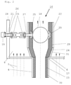
- FIG. 2 is a detail X of FIG. 1 as a longitudinal sectional view on an enlarged scale through an outlet end of a bypass tube of a heat exchanger according to the present invention with a control device arranged in the area of the outlet end.
- a heat exchanger 1 is schematically shown in a longitudinal section in FIG. 1 in a vertical arrangement.
- the heat exchanger 1 comprises a plurality of heat transfer tubes 3 and a centrally arranged bypass tube 4 , which are held each between a tube plate 5 of a gas inlet chamber 7 and a tube plate 6 of a gas outlet chamber 8 .
- the respective tube plates 5 , 6 are connected to a cylindrical jacket 2 , within which a jacket space 9 is formed.
- the heat transfer tubes 3 and the bypass tube 4 are enclosed in the jacket space 9 .
- a coolant 11 flows through the jacket space 9 .
- the bypass tube 4 is configured with a larger diameter than the heat transfer tubes 3 . Over a length of the bypass tube 4 , the bypass tube 4 has heat insulation 23 , on an inner tube wall 30 .
- the heat insulation 23 is intended and configured for the bypass tube 4 not releasing essentially any heat while the process gas stream 14 is flowing through.
- the coolant 11 flows into the jacket space 9 via at least one inlet pipe 10 arranged laterally at the cylindrical jacket 2 in the flow direction of the process gas stream 14 in front of the tube plate 6 of the gas outlet chamber 8 .
- the coolant 11 leaves the jacket space 9 as a water/vapor mixture via at least one outlet pipe 12 arranged laterally on the cylindrical jacket 2 behind the tube plate 5 of the gas inlet chamber 7 .
- the water/vapor mixture formed during the cooling is generated by indirect heat transfer via the jacket side of the heat transfer tubes 3 .
- An inlet pipe 13 , 13 . 1 is arranged in front of the tube plate 5 in the gas flow direction at the gas inlet chamber 7 laterally ( 13 ) or axially ( 13 . 1 —as is indicated by dotted line only).
- the process gas stream 14 flows through the inlet pipes 13 , 13 . 1 into the gas inlet chamber 7 and from there into the ends of the heat transfer tubes 3 held in the tube plate 5 and into the end of the bypass tube 4 , as is indicated by arrows.
- a discharge pipe 15 , 15 . 1 is arranged at the gas outlet chamber 8 laterally ( 15 ) or axially ( 15 . 1 ) behind the tube plate 6 in the gas flow direction.
- the process gas stream 14 leaves the gas outlet chamber 8 , which is connected to the ends of the heat transfer tubes 3 being held in the tube plate 6 and to the other end of the bypass tube 4 , from which split process gas streams escape, as is indicated by arrows, through said discharge pipes 15 , 15 . 1 .
- a control device 16 is arranged at the outlet end 17 of the bypass tube 4 .
- the control device 16 comprises a throttle valve (valve body) 18 in a valve housing 22 and a drive 19 arranged outside the heat exchanger 1 .
- the drive 19 is connected to a shaft 21 and double joints 20 and to an integrated shaft end 27 of the throttle valve 18 and forms a powertrain.
- the throttle valve 18 is arranged adjustably with the connected double joints 20 and with the shaft end 27 by means of the drive 19 via the shaft 21 .
- the double joints are intended essentially for compensating differences in thermal expansion between two bearings 25 for the respective integrated shaft end 27 of the throttle valve 18 in the valve housing 22 and a bearing 26 for the shaft 21 .
- the respective bearing 26 is formed in a heat insulation 24 , which is applied to an inner wall 29 of the valve housing 22 .
- the bearing 26 is arranged in a wall 28 of the gas outlet chamber 8 .
- the throttle valve (body) 18 is arranged rotatably at right angles to the gas flow direction in the valve housing 22 .
- the heat insulation 24 applied to the inner wall 29 of the valve housing 22 is preferably configured as a lining.
- the valve housing 22 is configured as an extension of the bypass tube 4 with equal diameter if the existing installation conditions at the heat exchanger 1 are sufficient. In case of crowded installation conditions, a configuration of the valve housing 22 as is shown in FIG. 2 is to be preferred, and the extension of the bypass tube 4 over a conical attachment 31 is configured as a transition from the outlet end 17 of the bypass tube to an expanded diameter.
- the throttle valve 18 connected to the drive 19 is provided for setting a gas outlet temperature of the heat exchanger 1 to a certain temperature range by mixing the cooled process gas stream 14 from the heat transfer tubes 3 with the uncooled process gas stream from the bypass tube 4 .
- a discharge speed (discharge rate) and a discharged quantity of the process gas stream 14 can be controlled with the throttle valve 18 , which is arranged in the immediate vicinity of the outlet end 17 of the bypass tube 4 and adjustable by means of the drive 19 of the control device 16 .
- the throttle valve 18 is made of a material resistant to high-temperature corrosion in the temperature range sensitive to high-temperature corrosion, which ranges from temperatures around 500° C. to an order of magnitude of about 850° C.
- the materials used as the control element for the throttle valve 18 are high-temperature-resistant or metal-dusting-resistant materials that have temperature stability and do not require special cooling.
- the valve housing 22 is manufactured from a material that is not necessarily fully resistant to high temperature corrosion, but is operated at a temperature outside of the range of high temperature corrosion. The valve housing 22 is protected by the insulation against high temperatures
- a ceramic material which has high-temperature-resistant or metal-dusting-resistant properties with temperature stability, is used as a material for the throttle valve 18 —particularly, the throttle valve body—is comprised of ceramic material or especially consists of a ceramic material.
- Components made of other materials are arranged heat insulated from the uncooled process gas stream 14 to the extent that these components can be used reliably according to the suitability of these materials.
Abstract
Description
Claims (20)
Applications Claiming Priority (2)
| Application Number | Priority Date | Filing Date | Title |
|---|---|---|---|
| DE102015013517.1A DE102015013517A1 (en) | 2015-10-20 | 2015-10-20 | Heat exchanger |
| DE102015013517.1 | 2015-10-20 |
Publications (2)
| Publication Number | Publication Date |
|---|---|
| US20170108282A1 US20170108282A1 (en) | 2017-04-20 |
| US11226159B2 true US11226159B2 (en) | 2022-01-18 |
Family
ID=57103761
Family Applications (1)
| Application Number | Title | Priority Date | Filing Date |
|---|---|---|---|
| US15/297,486 Active 2039-02-01 US11226159B2 (en) | 2015-10-20 | 2016-10-19 | Heat exchanger |
Country Status (12)
| Country | Link |
|---|---|
| US (1) | US11226159B2 (en) |
| EP (1) | EP3159646B2 (en) |
| JP (1) | JP2017078567A (en) |
| KR (1) | KR20170046090A (en) |
| CN (1) | CN106595353A (en) |
| BR (1) | BR102016024429A2 (en) |
| CA (1) | CA2943963A1 (en) |
| DE (1) | DE102015013517A1 (en) |
| ES (1) | ES2721310T3 (en) |
| HU (1) | HUE043660T2 (en) |
| PL (1) | PL3159646T3 (en) |
| TR (1) | TR201903875T4 (en) |
Families Citing this family (3)
| Publication number | Priority date | Publication date | Assignee | Title |
|---|---|---|---|---|
| CN108562075B (en) * | 2018-02-06 | 2024-02-06 | 北京华创瑞风空调科技有限公司 | Knockout and have its heat exchanger |
| DE102021107639A1 (en) | 2021-03-26 | 2022-09-29 | Mann+Hummel Gmbh | Water separator with a throttling element, use of a water separator and fuel cell system with a water separator |
| CN113756931B (en) * | 2021-08-19 | 2022-11-22 | 潍柴重机股份有限公司 | Marine heat exchanger, heat exchange system and heat exchange control method |
Citations (20)
| Publication number | Priority date | Publication date | Assignee | Title |
|---|---|---|---|---|
| US447285A (en) * | 1891-03-03 | albergee | ||
| US1918966A (en) * | 1930-06-20 | 1933-07-18 | Gen Chemical Corp | Apparatus for treating gas |
| US3477411A (en) * | 1967-12-22 | 1969-11-11 | Aqua Chem Inc | Heat recovery boiler with bypass |
| DE2846455B1 (en) | 1978-10-23 | 1979-10-31 | Borsig Gmbh | Tube bundle heat exchanger with a constant outlet temperature of one of the two media |
| DE8504717U1 (en) | 1985-02-20 | 1985-05-30 | Hermann Rappold & Co GmbH, 5160 Düren | MULTI-BLADE FLAP FOR HOT GASES |
| EP0356648A1 (en) | 1988-08-18 | 1990-03-07 | Deutsche Babcock- Borsig Aktiengesellschaft | Heat exchanger |
| DE3913422A1 (en) | 1989-04-24 | 1990-10-25 | Steinmueller Gmbh L & C | TUBE BUNDLE HEAT EXCHANGER |
| US5452686A (en) * | 1993-03-26 | 1995-09-26 | Haldor Topsoe A/S | Waste heat boiler |
| US5852990A (en) * | 1994-06-29 | 1998-12-29 | Haldor Topsoe A/S | Waste heat boiler |
| US6148909A (en) * | 1998-01-27 | 2000-11-21 | Komatsu Ltd. | Temperature control device and temperature control method |
| EP1498678A1 (en) | 2003-07-12 | 2005-01-19 | Borsig GmbH | Heat exchanger with a bypass tube |
| US7232000B2 (en) * | 2001-10-05 | 2007-06-19 | Gkn Driveline International Gmbh | Drive-steer axle for motor-driven vehicles |
| DE102005057674B4 (en) | 2005-12-01 | 2008-05-08 | Alstom Technology Ltd. | waste heat boiler |
| US20080244975A1 (en) * | 2002-01-04 | 2008-10-09 | Johnston Anthony M | Reforming apparatus and method |
| US20090065185A1 (en) * | 2006-01-23 | 2009-03-12 | Alstom Technology Ltd. | Tube Bundle Heat Exchanger |
| US20090293654A1 (en) | 2008-05-30 | 2009-12-03 | Woodward Governor Company | Tortionally Stiff, Thermally Isolating Shaft Coupling with Multiple Degrees of Freedom to Accommodate Misalignment |
| US20110059335A1 (en) * | 2003-08-28 | 2011-03-10 | Johan Hernblom | Composite Tube |
| DE102009048592A1 (en) | 2009-10-07 | 2011-04-14 | Lurgi Gmbh | Waste heat recovery boiler has multiple heat transfer tubes and bypass tube inside cylindrical outer cover, where heat transfer tubes and bypass tube have inlet end and outlet end |
| EP2312252A1 (en) | 2009-10-07 | 2011-04-20 | Lurgi GmbH | Waste heat boiler and method for cooling synthesis gas |
| WO2011089140A1 (en) | 2010-01-21 | 2011-07-28 | Shell Internationale Research Maatschappij B.V. | Heat exchanger and method of operating a heat exchanger |
Family Cites Families (13)
| Publication number | Priority date | Publication date | Assignee | Title |
|---|---|---|---|---|
| CA767520A (en) † | 1967-09-19 | A. Mccallister Robert | Heat exchanger control scheme | |
| US3199577A (en) † | 1962-06-14 | 1965-08-10 | Foster Wheeler Corp | Heat exchanger control scheme |
| EP0199838B1 (en) † | 1985-04-30 | 1991-07-17 | Asahi Glass Company Ltd. | Butterfly valve for controlling high-temperature fluid |
| ES2174739B1 (en) † | 2000-12-19 | 2003-11-01 | Valeo Termico Sa | HEAT EXCHANGER MODULE FOR AN EXHAUST GAS RECIRCULATION SYSTEM. |
| EP1343963B1 (en) † | 2000-12-19 | 2008-04-09 | Valeo Termico S.A. | Heat-exchanger module, specially designed for an exhaust gas recycling system |
| US20050133202A1 (en) † | 2001-11-09 | 2005-06-23 | Aalborg Industries A/S | Heat exchanger, combination with heat exchanger and method of manufacturing the heat exchanger |
| US7412845B2 (en) * | 2004-11-15 | 2008-08-19 | Sunbeam Products, Inc. | Ice cream maker including nestable canister assembly |
| JP5746353B2 (en) * | 2010-09-30 | 2015-07-08 | ハルドール・トプサー・アクチエゼルスカベット | Waste heat boiler |
| DE102012007721B4 (en) † | 2012-04-19 | 2022-02-24 | Thyssenkrupp Industrial Solutions Ag | Process gas cooler with lever-controlled process gas cooler flaps |
| CN203395204U (en) † | 2013-07-30 | 2014-01-15 | 温州东特蝶阀有限公司 | Novel ceramic butterfly valve |
| CN103471432B (en) † | 2013-09-26 | 2015-11-18 | 上海锅炉厂有限公司 | One has the board-like fixed tube-sheet exchanger of temperature controlling function double helix |
| CN203586173U (en) † | 2013-10-29 | 2014-05-07 | 内蒙古大唐国际克什克腾煤制天然气有限责任公司 | Waste heat boiler |
| CN203758309U (en) * | 2014-03-12 | 2014-08-06 | 中国科学院广州能源研究所 | Direct-turbulent flow oil cooler with variable pipe and shell side space |
-
2015
- 2015-10-20 DE DE102015013517.1A patent/DE102015013517A1/en not_active Withdrawn
-
2016
- 2016-09-30 PL PL16002142T patent/PL3159646T3/en unknown
- 2016-09-30 EP EP16002142.4A patent/EP3159646B2/en active Active
- 2016-09-30 CA CA2943963A patent/CA2943963A1/en not_active Abandoned
- 2016-09-30 HU HUE16002142A patent/HUE043660T2/en unknown
- 2016-09-30 ES ES16002142T patent/ES2721310T3/en active Active
- 2016-09-30 TR TR2019/03875T patent/TR201903875T4/en unknown
- 2016-10-18 JP JP2016204614A patent/JP2017078567A/en active Pending
- 2016-10-18 CN CN201610907503.6A patent/CN106595353A/en active Pending
- 2016-10-19 KR KR1020160135487A patent/KR20170046090A/en unknown
- 2016-10-19 US US15/297,486 patent/US11226159B2/en active Active
- 2016-10-19 BR BR102016024429-3A patent/BR102016024429A2/en active Search and Examination
Patent Citations (23)
| Publication number | Priority date | Publication date | Assignee | Title |
|---|---|---|---|---|
| US447285A (en) * | 1891-03-03 | albergee | ||
| US1918966A (en) * | 1930-06-20 | 1933-07-18 | Gen Chemical Corp | Apparatus for treating gas |
| US3477411A (en) * | 1967-12-22 | 1969-11-11 | Aqua Chem Inc | Heat recovery boiler with bypass |
| DE2846455B1 (en) | 1978-10-23 | 1979-10-31 | Borsig Gmbh | Tube bundle heat exchanger with a constant outlet temperature of one of the two media |
| DE8504717U1 (en) | 1985-02-20 | 1985-05-30 | Hermann Rappold & Co GmbH, 5160 Düren | MULTI-BLADE FLAP FOR HOT GASES |
| EP0356648A1 (en) | 1988-08-18 | 1990-03-07 | Deutsche Babcock- Borsig Aktiengesellschaft | Heat exchanger |
| US4993367A (en) * | 1988-08-18 | 1991-02-19 | Borsig Gmbh | Heat exchanger |
| DE3913422A1 (en) | 1989-04-24 | 1990-10-25 | Steinmueller Gmbh L & C | TUBE BUNDLE HEAT EXCHANGER |
| US5452686A (en) * | 1993-03-26 | 1995-09-26 | Haldor Topsoe A/S | Waste heat boiler |
| US5852990A (en) * | 1994-06-29 | 1998-12-29 | Haldor Topsoe A/S | Waste heat boiler |
| US6148909A (en) * | 1998-01-27 | 2000-11-21 | Komatsu Ltd. | Temperature control device and temperature control method |
| US7232000B2 (en) * | 2001-10-05 | 2007-06-19 | Gkn Driveline International Gmbh | Drive-steer axle for motor-driven vehicles |
| US20080244975A1 (en) * | 2002-01-04 | 2008-10-09 | Johnston Anthony M | Reforming apparatus and method |
| EP1498678A1 (en) | 2003-07-12 | 2005-01-19 | Borsig GmbH | Heat exchanger with a bypass tube |
| US20110059335A1 (en) * | 2003-08-28 | 2011-03-10 | Johan Hernblom | Composite Tube |
| DE102005057674B4 (en) | 2005-12-01 | 2008-05-08 | Alstom Technology Ltd. | waste heat boiler |
| US7412945B2 (en) * | 2005-12-01 | 2008-08-19 | Alstom Technology Ltd. | Waste heat boiler |
| US20090065185A1 (en) * | 2006-01-23 | 2009-03-12 | Alstom Technology Ltd. | Tube Bundle Heat Exchanger |
| US20090293654A1 (en) | 2008-05-30 | 2009-12-03 | Woodward Governor Company | Tortionally Stiff, Thermally Isolating Shaft Coupling with Multiple Degrees of Freedom to Accommodate Misalignment |
| DE102009048592A1 (en) | 2009-10-07 | 2011-04-14 | Lurgi Gmbh | Waste heat recovery boiler has multiple heat transfer tubes and bypass tube inside cylindrical outer cover, where heat transfer tubes and bypass tube have inlet end and outlet end |
| EP2312252A1 (en) | 2009-10-07 | 2011-04-20 | Lurgi GmbH | Waste heat boiler and method for cooling synthesis gas |
| WO2011089140A1 (en) | 2010-01-21 | 2011-07-28 | Shell Internationale Research Maatschappij B.V. | Heat exchanger and method of operating a heat exchanger |
| US20120305847A1 (en) * | 2010-01-21 | 2012-12-06 | Thomas Paul Von Kossak-Glowczewski | Heat exchanger and method of operating a heat exchanger |
Also Published As
| Publication number | Publication date |
|---|---|
| EP3159646A1 (en) | 2017-04-26 |
| CA2943963A1 (en) | 2017-04-20 |
| JP2017078567A (en) | 2017-04-27 |
| BR102016024429A2 (en) | 2017-10-10 |
| ES2721310T3 (en) | 2019-07-30 |
| HUE043660T2 (en) | 2019-08-28 |
| EP3159646B2 (en) | 2021-12-29 |
| US20170108282A1 (en) | 2017-04-20 |
| KR20170046090A (en) | 2017-04-28 |
| TR201903875T4 (en) | 2019-04-22 |
| PL3159646T3 (en) | 2019-07-31 |
| DE102015013517A1 (en) | 2017-04-20 |
| EP3159646B1 (en) | 2019-03-06 |
| CN106595353A (en) | 2017-04-26 |
Similar Documents
| Publication | Publication Date | Title |
|---|---|---|
| US11226159B2 (en) | Heat exchanger | |
| DK1793189T3 (en) | Waste heat boiler | |
| US10006719B2 (en) | Tube bundle heat exchanger having straight-tube configuration, process gas cooler, cooler for gas turbine cooling air, gas turbine or gas and steam turbine power plant, and method for the cooling of cooling air | |
| US20110048670A1 (en) | Method for the temperature-dependent setting of a sealing gap in a regenerative heat exchange, and the respective actuating apparatus | |
| US10281224B2 (en) | Heat exchanger | |
| RU2443959C2 (en) | Multiple-bed furnace | |
| JP2008224173A (en) | Two-tower type exhaust heat recovery system | |
| EA038419B1 (en) | Feed effluent heat exchanger | |
| KR101544733B1 (en) | Waste heat boiler with bypass and mixer | |
| CN100408915C (en) | Heating pipe device for making hot gas into waste heat boiler | |
| US3628508A (en) | Waste-heat boilers and like gas/liquid heat transfer systems | |
| KR20200011480A (en) | Cylindrical Manifold Equipment with Bypass | |
| HUE026848T2 (en) | Collecting line for tubular reformers | |
| US20020014323A1 (en) | Heat exchanging system | |
| KR100342207B1 (en) | A method for transporting at least one vapour substance through a vacuum chamber wall in a vacuum chamber and an apparatus for performing the method and the use thereof | |
| SE427962B (en) | PROCEDURE AND DEVICE FOR REFRIGERATING GAS HOCKS FOR WASTE GAS | |
| RU2453783C2 (en) | Multiple-bedded furnace | |
| CN102666160B (en) | For the heat exchanger of portable heating arrangement, portable heating arrangement and self-propelled vehicle | |
| US20120280496A1 (en) | Joint with heat-shielding element | |
| KR102026437B1 (en) | Apparatus for Testing Corrosion Characteristic of Boiler Tube | |
| FI12106U1 (en) | Insulation structure for a drying cylinder of a web forming machine and a drying cylinder for a web forming machine | |
| JP4108335B2 (en) | Heat exchanger | |
| EP0144189B1 (en) | Recuperator | |
| KR20160004195U (en) | A heat exchanger | |
| CZ17603U1 (en) | Reversible explosion-proof safety, particularly for pipe systems |
Legal Events
| Date | Code | Title | Description |
|---|---|---|---|
| AS | Assignment |
Owner name: BORSIG GMBH, GERMANY Free format text: ASSIGNMENT OF ASSIGNORS INTEREST;ASSIGNOR:MUEGGENBURG, JAN;REEL/FRAME:040063/0038 Effective date: 20160926 |
|
| STCV | Information on status: appeal procedure |
Free format text: APPEAL BRIEF (OR SUPPLEMENTAL BRIEF) ENTERED AND FORWARDED TO EXAMINER |
|
| STPP | Information on status: patent application and granting procedure in general |
Free format text: NON FINAL ACTION MAILED |
|
| STPP | Information on status: patent application and granting procedure in general |
Free format text: RESPONSE TO NON-FINAL OFFICE ACTION ENTERED AND FORWARDED TO EXAMINER |
|
| STPP | Information on status: patent application and granting procedure in general |
Free format text: FINAL REJECTION MAILED |
|
| STCV | Information on status: appeal procedure |
Free format text: NOTICE OF APPEAL FILED |
|
| STCV | Information on status: appeal procedure |
Free format text: APPEAL BRIEF (OR SUPPLEMENTAL BRIEF) ENTERED AND FORWARDED TO EXAMINER |
|
| STCV | Information on status: appeal procedure |
Free format text: ON APPEAL -- AWAITING DECISION BY THE BOARD OF APPEALS |
|
| STCV | Information on status: appeal procedure |
Free format text: BOARD OF APPEALS DECISION RENDERED |
|
| STPP | Information on status: patent application and granting procedure in general |
Free format text: NOTICE OF ALLOWANCE MAILED -- APPLICATION RECEIVED IN OFFICE OF PUBLICATIONS |
|
| STPP | Information on status: patent application and granting procedure in general |
Free format text: PUBLICATIONS -- ISSUE FEE PAYMENT RECEIVED |
|
| STPP | Information on status: patent application and granting procedure in general |
Free format text: PUBLICATIONS -- ISSUE FEE PAYMENT VERIFIED |
|
| STCF | Information on status: patent grant |
Free format text: PATENTED CASE |