US11225792B2 - Insulating construction panels, systems and methods - Google Patents
Insulating construction panels, systems and methods Download PDFInfo
- Publication number
- US11225792B2 US11225792B2 US15/588,578 US201715588578A US11225792B2 US 11225792 B2 US11225792 B2 US 11225792B2 US 201715588578 A US201715588578 A US 201715588578A US 11225792 B2 US11225792 B2 US 11225792B2
- Authority
- US
- United States
- Prior art keywords
- panel
- panels
- construction
- bottom end
- top end
- Prior art date
- Legal status (The legal status is an assumption and is not a legal conclusion. Google has not performed a legal analysis and makes no representation as to the accuracy of the status listed.)
- Active
Links
Images


Classifications
-
- E—FIXED CONSTRUCTIONS
- E04—BUILDING
- E04B—GENERAL BUILDING CONSTRUCTIONS; WALLS, e.g. PARTITIONS; ROOFS; FLOORS; CEILINGS; INSULATION OR OTHER PROTECTION OF BUILDINGS
- E04B2/00—Walls, e.g. partitions, for buildings; Wall construction with regard to insulation; Connections specially adapted to walls
- E04B2/84—Walls made by casting, pouring, or tamping in situ
- E04B2/86—Walls made by casting, pouring, or tamping in situ made in permanent forms
- E04B2/8652—Walls made by casting, pouring, or tamping in situ made in permanent forms with ties located in the joints of the forms
-
- E—FIXED CONSTRUCTIONS
- E04—BUILDING
- E04B—GENERAL BUILDING CONSTRUCTIONS; WALLS, e.g. PARTITIONS; ROOFS; FLOORS; CEILINGS; INSULATION OR OTHER PROTECTION OF BUILDINGS
- E04B1/00—Constructions in general; Structures which are not restricted either to walls, e.g. partitions, or floors or ceilings or roofs
- E04B1/16—Structures made from masses, e.g. of concrete, cast or similarly formed in situ with or without making use of additional elements, such as permanent forms, substructures to be coated with load-bearing material
- E04B1/167—Structures made from masses, e.g. of concrete, cast or similarly formed in situ with or without making use of additional elements, such as permanent forms, substructures to be coated with load-bearing material with permanent forms made of particular materials, e.g. layered products
-
- E—FIXED CONSTRUCTIONS
- E04—BUILDING
- E04B—GENERAL BUILDING CONSTRUCTIONS; WALLS, e.g. PARTITIONS; ROOFS; FLOORS; CEILINGS; INSULATION OR OTHER PROTECTION OF BUILDINGS
- E04B1/00—Constructions in general; Structures which are not restricted either to walls, e.g. partitions, or floors or ceilings or roofs
- E04B1/62—Insulation or other protection; Elements or use of specified material therefor
- E04B1/92—Protection against other undesired influences or dangers
- E04B1/94—Protection against other undesired influences or dangers against fire
- E04B1/941—Building elements specially adapted therefor
- E04B1/942—Building elements specially adapted therefor slab-shaped
-
- E—FIXED CONSTRUCTIONS
- E04—BUILDING
- E04B—GENERAL BUILDING CONSTRUCTIONS; WALLS, e.g. PARTITIONS; ROOFS; FLOORS; CEILINGS; INSULATION OR OTHER PROTECTION OF BUILDINGS
- E04B2/00—Walls, e.g. partitions, for buildings; Wall construction with regard to insulation; Connections specially adapted to walls
- E04B2/02—Walls, e.g. partitions, for buildings; Wall construction with regard to insulation; Connections specially adapted to walls built-up from layers of building elements
- E04B2/14—Walls having cavities in, but not between, the elements, i.e. each cavity being enclosed by at least four sides forming part of one single element
- E04B2/16—Walls having cavities in, but not between, the elements, i.e. each cavity being enclosed by at least four sides forming part of one single element using elements having specially-designed means for stabilising the position
- E04B2/18—Walls having cavities in, but not between, the elements, i.e. each cavity being enclosed by at least four sides forming part of one single element using elements having specially-designed means for stabilising the position by interlocking of projections or inserts with indentations, e.g. of tongues, grooves, dovetails
-
- E—FIXED CONSTRUCTIONS
- E04—BUILDING
- E04B—GENERAL BUILDING CONSTRUCTIONS; WALLS, e.g. PARTITIONS; ROOFS; FLOORS; CEILINGS; INSULATION OR OTHER PROTECTION OF BUILDINGS
- E04B2/00—Walls, e.g. partitions, for buildings; Wall construction with regard to insulation; Connections specially adapted to walls
- E04B2/02—Walls, e.g. partitions, for buildings; Wall construction with regard to insulation; Connections specially adapted to walls built-up from layers of building elements
- E04B2/14—Walls having cavities in, but not between, the elements, i.e. each cavity being enclosed by at least four sides forming part of one single element
- E04B2/26—Walls having cavities in, but not between, the elements, i.e. each cavity being enclosed by at least four sides forming part of one single element the walls being characterised by fillings in all cavities in order to form a wall construction
-
- E—FIXED CONSTRUCTIONS
- E04—BUILDING
- E04B—GENERAL BUILDING CONSTRUCTIONS; WALLS, e.g. PARTITIONS; ROOFS; FLOORS; CEILINGS; INSULATION OR OTHER PROTECTION OF BUILDINGS
- E04B2/00—Walls, e.g. partitions, for buildings; Wall construction with regard to insulation; Connections specially adapted to walls
- E04B2/84—Walls made by casting, pouring, or tamping in situ
- E04B2/86—Walls made by casting, pouring, or tamping in situ made in permanent forms
- E04B2002/867—Corner details
Definitions
- the present disclosure relates to construction panels and, in particular, to insulating constructions panels, systems and methods.
- foundation or wall
- the function of a foundation is to support the weight of the structure and to provide a level surface to build on.
- the foundation will also often form the wall of a portion of the structure such as a basement wall.
- Foundations can be built from various types of materials including stone, brick, concrete block, treated lumber or poured concrete. Of these, poured concrete is one of the most widely used materials.
- Poured concrete foundations have been built using various types of methods and can include poured slabs as well as raised perimeter foundations.
- One of the oldest and most basic methods of forming a poured concrete raised perimeter foundation is to use wooden forms. This method involves placing two parallel wooden structures spaced a predetermined distance from each other along the footprint or perimeter of the structure to be constructed. Concrete is a material that is very strong in compression but is relatively weak in tension. Accordingly a reinforcing bar, also known as rebar, is normally used in this type of construction and is cast into the concrete to carry the tensile loads. The rebar is arranged at predetermined positions within the parallel wooden structures and held in place with wood and/or metal ties. The concrete is then poured into the space between the wooden structures and allowed to set. After setting, the wooden structures are removed, leaving the poured concrete foundation upon which the structure can be built.
- a reinforcing bar also known as rebar
- insulating concrete form systems known as insulated concrete forms or blocks
- these systems include interlocking blocks that are formed from a pair of opposed foam panels connected together in a spaced, parallel relationship by a plurality of tie members to define a concrete receiving cavity.
- the blocks are aligned and stacked to define a wall, and concrete is poured into the concrete receiving cavities.
- the blocks are maintained in place after the concrete hardens to insulate the concrete, provide a sound barrier, insulation, and serve as a backing for finishing material.
- This application describes (in the form of methodologies, apparatuses, and systems) for insulating construction panels, systems and methods.
- An insulated construction panel having a top end, a bottom end, a first end, a second end, a front side and a rear side, the panel for constructing a single or multi-thickness concrete form, the panel including regularly spaced coplanar passages extending completely through the panel from the top end of the panel toward and through to the bottom end of the panel.
- an angular passage perpendicularly intersecting each coplanar passage at the top end and extending toward and through a portion of a front side surface of the front side and rear side surface of the rear side of the panel, each angular passage extending only partially through the panel from the top end toward the bottom end.
- each angular passage perpendicularly intersecting each coplanar passage at the bottom end and extending toward and through a portion of the front side surface of the front side and the rear side surface of rear side of the panel, each angular passage extending only partially through the panel from the bottom end toward the top end.
- a fire proof construction panel for constructing a single or multi-thickness concrete form including regularly spaced coplanar passages extending completely through the panel from a top end of the panel toward and through to a bottom end of the panel, for each of the regularly spaced coplanar passages, an angular passage perpendicularly intersecting each coplanar passage at the top end and extending toward and through a front side and a portion of a rear side surface of a rear side of the panel, each angular passage extending only partially through the panel from the top end toward the bottom end and for each of the regularly spaced coplanar passages, an angular passage perpendicularly intersecting each coplanar passage at the bottom end and extending toward and through the front side and a portion of the rear side surface of rear side of the panel, each angular passage extending only partially through the panel from the bottom end toward the top end.
- a concrete form system includes a plurality of construction panels, an insertable tie for interconnecting the plurality of construction panels and a flat-shaped molding for interlocking one or more of the plurality of construction panels.
- FIG. 1 is a perspective view of the front side of an insulating construction panel according to an illustrative embodiment of the present disclosure
- FIG. 2 is a perspective view of a rear side of the insulating construction panel according to an illustrative embodiment of the present disclosure.
- FIG. 3 is a top end or bottom end plan view of a construction panel according to an illustrative embodiment of the present disclosure
- FIG. 4 an end view of a construction panel according to an illustrative embodiment of the present disclosure
- FIG. 5 is a perspective view of a tie according to an illustrative embodiment of the present disclosure.
- FIG. 6 is a bottom end plan view of a tie according to an illustrative embodiment of the present disclosure.
- FIG. 7 is a side view of a tie according to an illustrative embodiment of the present disclosure.
- FIG. 8 is a fragmental perspective view of flat-shaped molding according to an illustrative embodiment of the present disclosure.
- FIG. 9 is an end view of a flat-shaped molding according to an illustrative embodiment of the present disclosure.
- FIG. 10 is a fragmental plan view of a flat-shaped molding according to an illustrative embodiment of the present disclosure.
- FIG. 11 is a fragmental perspective view of an insulating concrete form constructed utilizing illustrative embodiments of the present disclosure
- FIG. 12 is a fragmental perspective view of an insulating concrete form according to an illustrative embodiment of the present disclosure showing the ends of panels without an insertable tie;
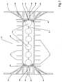
- FIGS. 13A and 13B are top end and bottom end plan views, respectively, of the insulating concrete form of FIG. 11 according to an illustrative embodiment of the present disclosure
- FIG. 14 is an end view of an assembled insulating concrete form according to an illustrative embodiment of the present disclosure with tie removed from the end of form;
- FIG. 15 is an end view of an assembled insulating concrete form according to an illustrative embodiment of the present disclosure showing full ties;
- FIG. 16 is an elevation view of an assembled insulating concrete form according to an illustrative embodiment of the present disclosure, showing locations of insertable ties located within the front end of the construction panels;
- FIG. 17 is a perspective view of an assembled corner form according to an illustrative embodiment of the present disclosure, showing construction panels, ties and flat-shaped moldings;
- FIG. 18 is a plan view of an assembled corner form according to an illustrative embodiment of the present disclosure showing construction panels, ties and flat-shaped moldings;
- FIG. 19 is a perspective view of a multi-thickness insulating concrete form according to an illustrative embodiment of the present disclosure.
- FIG. 20 is a plan view of a multi-thickness insulating concrete form according to an illustrative embodiment of the present disclosure
- FIG. 21 is an end view of a multi-thickness insulating concrete form according to an illustrative embodiment of the present disclosure with half-ties at bottom end of construction panel;
- FIG. 22 is a perspective view of the front side of an insulating construction panel according to an illustrative embodiment of the present disclosure.
- FIG. 23 is a perspective view of a rear side of the insulating construction panel according to an illustrative embodiment of the present disclosure.
- FIG. 24 is a top end or bottom end plan view of a construction panel according to an illustrative embodiment of the present disclosure.
- FIG. 25 is an end view of a construction panel according to an illustrative embodiment of the present disclosure.
- FIG. 26 is a fragmental perspective view of an concrete form including one type of insulating construction panels on one side and a different type of insulating construction panels on the other side according to an illustrative embodiment of the present disclosure
- FIG. 27 is a fragmental perspective view of an insulating concrete form according to an illustrative embodiment of the present disclosure showing the ends of panels with an insertable tie;
- FIGS. 28A and 28B are top end and bottom end plan views, respectively, of the insulating concrete form of FIG. 26 according to an illustrative embodiment of the present disclosure
- FIG. 29 is an end view of an assembled insulating concrete form according to an illustrative embodiment of the present disclosure with tie removed from the end of form;
- FIG. 30 is an end view of an assembled insulating concrete form according to an illustrative embodiment of the present disclosure showing full ties.
- FIG. 17 An insulating panel construction system according to an illustrative embodiment of the present disclosure is shown in FIG. 17 .
- the system has several components including, for example, interlocking panels 10 (e.g., 10 a - 10 d ) forming sides of the concrete form.
- Insertable ties 14 are provided for maintaining the panels a predetermined distance apart forming a space between panels for concrete to be poured.
- Flat-shaped moldings 56 are provided for tying a plurality of the interlocking panels together at corners of the concrete form.
- the insulating panel construction system When the insulating panel construction system according to illustrative embodiments of the present disclosure is erected, concrete is poured into the cavities between the panels. After the concrete sets, the panel construction system is maintained in place. The panels insulate the concrete, provide a sound barrier, insulation, and serve as a backing for finishing material.
- FIGS. 1 and 2 illustrate perspective views of a front side 48 and a rear side 32 , respectively, of an insulating construction panel 10 according to an embodiment of the present disclosure.
- Insulating construction panel 10 includes an end 26 and an end 28 , top end 20 and bottom end 22 , a front side 48 and a rear side 32 .
- Front side 48 has a generally horizontal ridge or marking 46 indicating a best location for horizontal grooving and utility installation as will be described later below.
- Regularly spaced vertical grooves or markings 88 are provided to aid in measurements for cutting and indicate locations of elongated plates that extend into passages 34 in the panel 10 . This allows screws or other attachments to be inserted through the front side 48 of panel 10 and into the elongated plates for finishes attachment.
- Top end 20 and bottom end 22 include a flat shaped depression or recess 24 extending from end 26 to end 28 .
- the height of panel 10 from top end 20 to bottom end 22 may be any suitable dimension. For example, depending on a particular application, the height may be approximately 12′′.
- the thickness of panel 10 may also be any suitable dimension. For example, depending on a particular application, the thickness of panel 10 may be approximately 2.5′′.
- a plurality of similarly dimensioned, alternating projections 18 and recesses 16 are also equally spaced between end 26 and end 28 . Drainage grooves 30 extend from recesses 16 to the rear side 32 of panel 10 .
- Regularly spaced coplanar passages 34 extend through the insulating construction panel 10 from the top end 20 to the bottom end 22 .
- passages 36 For each of coplanar passage 34 there are two perpendicularly intersecting angular passages 36 extending from the top end 20 and bottom end 22 through rear side 32 and front side 48 . As shown in FIG. 1 , passages 36 extend through a front side surface of the front side 48 and form slots 37 at the top end 20 and bottom end 22 . As shown in FIG. 2 , passages 36 also extend through a rear side surface of the rear side 32 and form slots 39 at the top end 20 and bottom end 22 . Small recesses 38 are located within the flat shaped depression or recess 24 on both sides of angular passages 36 .
- top end 20 and bottom end 22 include flat shaped depressions or recesses 24 .
- the flat-shaped recesses 24 extend from first end 26 of panel 10 to the second end 28 of panel 10 .
- the top end 20 includes a plurality of similarly dimensioned, alternating projections 18 and recesses 16 equally spaced between first end 26 and second end 28 .
- drainage grooves 30 extend from recesses 16 through the rear side 32 of the panel 10 .
- Regularly spaced coplanar passages 34 extend through the panel 10 from the top end 20 to the bottom end 22 .
- each coplanar passage 34 there are two perpendicularly intersecting angular passages 36 extending from the top end 20 and bottom end 22 and through to rear side 32 and front side 48 .
- Recesses 38 are located within the flat shaped recess 24 on both sides of angular passages 36 .
- FIGS. 5-7 illustrate views of a tie 14 , according to illustrative embodiments of the present disclosure.
- Tie 14 includes spacer 66 , perpendicular stoppers 68 with V-shaped notches 74 , angular connectors 60 , and perpendicular elongated plates 44 with horizontal marking 80 along the center and including a V-shaped notch 81 .
- notch 74 is relatively smaller than notch 81 .
- Regularly spaced pins 72 are located on at least one of the top and bottom of spacer 66 . Pins 72 are provided allowing rebar or other structural members to be added to the foundation as desired and to keep additional layers of insulating construction panels in a desired position.
- Angular connectors 60 include centrally located flat-shaped passages 58 and tabs 84 extending perpendicularly from angular connector 60 on both sides above and below flat-shaped passages 58 .
- the V-shaped notches 74 , 81 and horizontal marking and/or notch 78 allow the tie 14 to be split into two halves without the use of any cutting tools. For example, ties 14 may be snapped in half along notches 74 , 78 and 81 .
- the length of tie 14 may be provided in any suitable dimension.
- center spacer 66 spanning stoppers 68 may be 6′′, 8′′, 10′′, 12′′, 14′′, etc.
- Elongated plates 44 may be, for example, approximately just under 12′′ high, also depending on a particular application.
- FIGS. 8-10 illustrate views of a flat-shaped molding 56 according to an illustrative embodiment of the present disclosure.
- Flat-shaped molding 56 includes web 90 .
- Web 90 includes regularly spaced orifices 94 .
- Regularly spaced orifices 94 are dimensioned to receive regularly spaced projections 18 on panels 10 .
- Flat-shaped molding 56 and ties 14 can be made of any suitable type of material such as, for example, plastics, metals, alloys, etc. or combinations of such materials.
- FIG. 11 illustrates portions of two identical insulating construction panels 10 interlocked with a plurality of insertable ties 14 at the top end 20 of panels 10 and a plurality of half-ties of the insertable ties 14 at the bottom end 22 of panels 10 according to an illustrative embodiment of the present disclosure.
- the ties 14 hold panels 10 in a fixed spaced parallel relationship, thereby defining the cavity dimension of the concrete form.
- Panels 10 are adapted to be stacked and interlocked with other insulating construction panels by the plurality of ties 14 , recesses 16 and projections 18 in a bi-directional and/or reversible manner.
- Vertical grooves or markings 88 provide references for indicating location of the elongated plates 44 and aid in measuring and evenly cutting the panels 10 . Plates 44 make secure attachment points for nails, screws, etc. used for mounting finishing materials to the face of panels 10 .
- FIG. 12 illustrates portions of two identical insulating construction panels 10 interlocked with a plurality of insertable ties 14 at the top end 20 of panels 10 and a plurality of half-ties of the insertable ties 14 at the bottom end 22 of panels 10 according to an illustrative embodiment of the present disclosure.
- the ties 14 have been removed from an end 26 of construction panels 10 for ease of viewing. Screws, nails, etc. can be driven through tabs 84 and into flat-shaped molding 56 (not shown) to hold ties 14 in place against panels 10 if necessary.
- FIGS. 13A and 13B illustrate two identical insulating construction panels 10 interlocked with a plurality of insertable ties 14 at the bottom end 22 ( FIG. 13A ) and top end 20 ( FIG. 13B ) of panels 10 according to an illustrative embodiment of the present disclosure.
- FIGS. 14 and 15 illustrate end views of the assembled single thickness concrete form 40 according to an illustrative embodiment of the present disclosure.
- the form 40 includes opposing construction panels 10 interlocked with a plurality of insertable ties 14 .
- Ties 14 are inserted into coplanar passages 34 and angular passages 36 at the top end 20 and bottom end 22 of construction panels 10 .
- There are small gaps 42 (see FIG. 15 ) between elongated plates 44 for easy cutting and utility installation in construction panels 10 .
- Continuous horizontal marking 46 at front side 48 of construction panel 10 indicate a best location for horizontal grooving and installation of utilities.
- FIG. 16 illustrates a side view of a portion of an assembled wall elevation 50 according to an illustrative embodiment of the present disclosure formed of a plurality of overlapping rows of vertically and horizontally aligned construction panels 10 connected with a plurality of ties 14 inserted into coplanar passages 34 and angular passages 36 at the top end 20 and bottom end 22 of construction panels 10 .
- the interlocking of rows of construction panels results in perfect alignment of ties 14 and elongated plates 44 throughout the entire wall. Perfect alignment of elongated plates 44 greatly improves installation of wall finishes.
- Small gaps 42 between elongated plates 44 located in the center of each construction panel 10 greatly improve ease of cutting grooves and installation of utilities. Central location of gap 42 within each construction panel 10 prevents fresh concrete from entering into the preferred location for grooving and installing utilities within the construction panels 10 thus preventing damage to tools used to form the grooving.
- FIG. 17 illustrates a perspective view of a single thickness corner form assembled with four identical construction panels 10 ( 10 a , 10 b , 10 c and 10 d ) interlocked with a plurality of ties 14 and four flat-shaped moldings 56 .
- Flat-shaped molding 56 is shaped and dimensioned to be inserted through the flat-shaped passage 58 located in the center part of angular connectors 60 (e.g., see FIG. 7 ) and placed over the protrusions 18 of construction panels 10 into the flat-shaped recesses 24 .
- Flat-shaped moldings 56 overlap each other and interlock together at four points 62 .
- the ties 14 that crisscross in the corner as shown in FIG. 17 are standard ties described above.
- the ties 14 may be altered in the field by cutting through spacer 66 thru to orifices 76 or by simply snapping the ties 14 in half as described above (e.g., see FIG. 7 ). Ties 14 are cut on one side of corner assembly to allow ties 14 on the other side of the corner assembly to pass there through.
- FIG. 18 illustrates a plan view of a corner of the single thickness form assembled with four identical construction panels 10 ( 10 a - 10 d ) interlocked with the plurality of ties 14 and four flat-shaped moldings 56 according to an illustrative embodiment of the present disclosure.
- Flat-shaped molding 56 is inserted through the flat-shaped passage 58 located in the center part of angular connectors 60 and placed over the protrusions 18 of construction panels 10 and into the flat-shaped recesses 24 .
- a multi-thickness form can be used to provide an additional layer of insulation, sound barrier, etc.
- a single thickness form such as those described above may have a temperature transfer resistance (R-Value) of R22.
- a multi-thickness form may achieve an R-Value of at least up to R55.
- a multi-thickness form 70 as shown in FIGS. 19-21 is provided.
- the multi-thickness form is similar to the single thickness form described above but includes several additional features. As shown, multi-thickness form 70 includes additional layers of panels 10 placed directly behind an external layer of panels 10 .
- Regularly spaced angular passages 36 and notches 37 , 39 at the top end 20 and bottom end 22 of additional layers of construction panels 10 are adapted to fit over spacers 66 on ties 14 .
- the same construction panels 10 may thus be used to make single or multiple thickness forms without a need to make any alterations to the construction panels 10 or ties 14 .
- FIGS. 22 and 23 illustrate perspective views of a front side 848 and a rear side 832 , respectively, of an insulating construction panel 800 according to another illustrative embodiment of the present disclosure.
- construction panels 800 may be made with other types of material including but not limited to, for example, fire proof material such as aerated autoclaved concrete. Due to the different manufacturing process, construction panels 800 may be made with or without recesses 16 , projections 18 , drainage grooves 30 , horizontal marking 46 , and vertical grooves or markings 88 as described above with respect to other illustrative embodiments.
- angular passages 836 may extend from the top end 820 to the bottom end 822 and through the entire height of rear side 832 of panel 800 .
- Small recess 838 may extend from first end 826 through the second end 828 at the top end 820 and bottom end 822 of construction panel 800 .
- top end 820 and bottom end 822 include flat shaped recesses 824 .
- the flat-shaped recesses 824 extend from first end 826 of panel 800 to the second end 828 of panel 800 .
- the top end 820 does not include alternating projections and recesses as shown and described above with respect to other illustrative embodiments.
- Regularly spaced coplanar passages 834 extend through the panel 800 from the top end 820 to the bottom end 822 . For each coplanar passage 834 there is one perpendicularly intersecting passage 836 extending from the top end 820 and bottom end 822 and through to rear side 832 .
- Small recesses 838 are located within the flat shaped recesses 824 and extend from first end 826 of panel 800 to the second end 828 of panel 800 .
- concrete construction forms may be assembled utilizing just insulating construction panels 10 or tire proof construction panels 800 or any combination of the above-described construction panels.
- a concrete construction form may be assembled utilizing insulating construction panels 10 on one side and fire proof construction panels 800 on the other side.
- the concrete construction form may be assembled utilizing fire proof construction panels 800 on both sides of the form if desired.
- FIG. 26 illustrates portions of an insulating construction panel 10 and a fire proof construction panel 800 interlocked with a plurality of insertable ties 14 at the top end 20 of insulating construction panel 10 and a top end 820 of fire proof construction panel 800 and a plurality of half-ties of the insertable ties 14 at the bottom end 22 of insulating construction panel 10 and the bottom end 822 of fire proof construction panel 800 according to an illustrative embodiment of the present disclosure.
- the ties 14 hold panels 10 and 800 in a fixed spaced parallel relationship, thereby defining the cavity dimension of the concrete form.
- insulating construction panels 10 are adapted to be stacked and interlocked with other like panels by the plurality of ties 14 , recesses 16 and projections 18 in a bi-directional and/or reversible manner.
- Vertical grooves or markings 88 provide references for indicating location of the elongated plates 44 and aid in measuring and evenly cutting the panels 10 . Plates 44 make secure attachment points for nails, screws, etc. used for mounting finishing materials to the face of panels 10 .
- Fire proof construction panels 800 are adapted to be stacked and interlocked with other like panels by the plurality of ties 14 in a bi-directional and/or reversible manner.
- FIG. 27 illustrates portions of an insulating construction panel 10 and a fire proof construction panel 800 interlocked with a plurality of insertable ties 14 at the top end 20 of insulating construction panel 10 and a top end 820 of fire proof construction panel 800 and a plurality of half-ties of the insertable ties 14 at the bottom end 22 of insulating construction panel 10 and the bottom end 822 of fire proof construction panel 800 according to an illustrative embodiment of the present disclosure.
- the ties 14 have been removed from end 26 of construction panel 10 and end 826 of fire proof construction panel 800 for ease of viewing. Screws, nails, etc. can be driven through tabs 84 and into flat-shaped molding 56 (not shown) to hold ties 14 in place against insulating construction panels 10 and/or fire proof construction panel 800 if desired.
- FIGS. 28A and 28B illustrate an insulating construction panel 10 and a fire proof construction panel 800 interlocked with a plurality of insertable ties 14 at the bottom end 22 of insulating construction panel 10 and the bottom end 822 of fire proof construction panel 800 ( FIG. 28A ) and the top end 20 of insulating construction panel 10 and the top end 820 of fire proof construction panel 800 ( FIG. 28B ) according to an illustrative embodiment of the present disclosure.
- FIGS. 29 and 30 illustrate end views of the assembled single thickness concrete form 840 including an insulating construction panel 10 and a fire proof construction panel 800 according to an illustrative embodiment of the present disclosure.
- the form 840 includes opposing construction panel 10 and fire proof construction panel 800 interlocked with a plurality of insertable ties 14 .
- Ties 14 are inserted into coplanar passages 34 and 834 and angular passages 36 and 836 at the top ends 20 and 820 and bottom ends 22 and 822 of insulating construction panels 10 and fire proof construction panels 800 .
- There are small gaps 42 between elongated plates 44 for easy cutting and utility installation in construction panels 10 .
- Continuous horizontal marking 46 at front side 48 of construction panel 10 indicate a best location for horizontal grooving and installation of utilities.
- Illustrative embodiments of the present disclosure provide several salient features. For example, according to illustrative embodiments of the present disclosure, it is not necessary to mold webs, spacers, or ties into the insulating construction panels which results in lower labor costs during production. Since the ties are not permanently embedded in the insulating construction panels, tie scraps can be easily recycled. In addition, because the insulating construction panels can be manufactured from only one type of material, recycling of scraps is easier, less expensive, and improves “Green Building” practice.
- the present system is comprised of only three components: insulating construction panels 10 (and/or fire proof construction panels 800 ), ties 14 and flat moldings 56 . This allows the components to be packed and shipped using less volume than those using pre-molded forms and corner panels, thus providing savings on storage, shipping and handling.
- all of the insulating construction panels are interlocked by vertically lined up ties which cannot shift, therefore providing a reliable location for attaching finishing materials.
- the horizontal utility installation spot is located in the center of the insulating construction panels, away from ties and concrete which, in prior systems, would get in between panels during the concrete pour. This makes installation of utilities easier and results in fewer damaged tools that would otherwise be damaged by contact with stray concrete.
- pins 72 in the ties 14 greatly improve installation and removal of reinforcing bars or tools like chalk line or measuring tape. Pins 72 also aid in installing and holding additional layers of panels 10 in the desired position during assembly of multiple thickness forms.
- the insulating construction panels can be made from a single component, many different materials can be used to make them. For example, foam panels provide excellent insulating volume. In addition, autoclaved aerated concrete panels provide great fire protection. Panels with a finishing surface can be used on one side to provide finished elevation without installation of additional materials. A combination of different panels can be used with multi-thickness forms to, for example, provide fire resistant panels on one side, insulating panels on the inner layer and finishing panels on the other side. Of course, the use of other combinations and/or types of materials is contemplated by the present disclosure.
Landscapes
- Engineering & Computer Science (AREA)
- Architecture (AREA)
- Physics & Mathematics (AREA)
- Electromagnetism (AREA)
- Civil Engineering (AREA)
- Structural Engineering (AREA)
- Building Environments (AREA)
Abstract
Description
Claims (20)
Priority Applications (1)
| Application Number | Priority Date | Filing Date | Title |
|---|---|---|---|
| US15/588,578 US11225792B2 (en) | 2016-05-05 | 2017-05-05 | Insulating construction panels, systems and methods |
Applications Claiming Priority (2)
| Application Number | Priority Date | Filing Date | Title |
|---|---|---|---|
| US201662391636P | 2016-05-05 | 2016-05-05 | |
| US15/588,578 US11225792B2 (en) | 2016-05-05 | 2017-05-05 | Insulating construction panels, systems and methods |
Publications (2)
| Publication Number | Publication Date |
|---|---|
| US20190093348A1 US20190093348A1 (en) | 2019-03-28 |
| US11225792B2 true US11225792B2 (en) | 2022-01-18 |
Family
ID=65808871
Family Applications (1)
| Application Number | Title | Priority Date | Filing Date |
|---|---|---|---|
| US15/588,578 Active US11225792B2 (en) | 2016-05-05 | 2017-05-05 | Insulating construction panels, systems and methods |
Country Status (1)
| Country | Link |
|---|---|
| US (1) | US11225792B2 (en) |
Families Citing this family (4)
| Publication number | Priority date | Publication date | Assignee | Title |
|---|---|---|---|---|
| CN107859232B (en) * | 2017-12-14 | 2023-07-18 | 陕西凝远新材料科技股份有限公司 | Sand aerated concrete plate with embedded wire box wire pipes and preparation method thereof |
| US12084858B2 (en) | 2021-03-01 | 2024-09-10 | Logix Brands Ltd. | Concrete form assembly |
| US12044018B2 (en) | 2021-03-01 | 2024-07-23 | Logix Brands Ltd. | Concrete form assembly |
| US11668089B2 (en) | 2021-03-01 | 2023-06-06 | Logix Brands Ltd | Concrete form assembly |
Citations (29)
| Publication number | Priority date | Publication date | Assignee | Title |
|---|---|---|---|---|
| US738643A (en) | 1902-08-18 | 1903-09-08 | Benjamin F Van Camp | Building-block. |
| US3428933A (en) * | 1966-08-29 | 1969-02-18 | Automation Ind Inc | Strain gage unit and method of applying the gage |
| US4884382A (en) | 1988-05-18 | 1989-12-05 | Horobin David D | Modular building-block form |
| US5428933A (en) | 1994-02-14 | 1995-07-04 | Philippe; Michel | Insulating construction panel or block |
| US5465542A (en) | 1992-05-29 | 1995-11-14 | Terry; Verl O. | Interblocking concrete form modules |
| US5557894A (en) * | 1995-02-13 | 1996-09-24 | Stectus Systems-Midwest | Window assembly frame |
| US5566521A (en) | 1994-08-10 | 1996-10-22 | Andrews; Richard E. | Building structure and method |
| US5625989A (en) | 1995-07-28 | 1997-05-06 | Huntington Foam Corp. | Method and apparatus for forming of a poured concrete wall |
| US5704180A (en) | 1994-05-10 | 1998-01-06 | Wallsystems International Ltd. | Insulating concrete form utilizing interlocking foam panels |
| US5729936A (en) | 1995-10-03 | 1998-03-24 | Maxwell; James F. | Prefab fiber building construction |
| US6108990A (en) * | 1998-05-15 | 2000-08-29 | Klamer; Steven M. | Connector for building panels |
| US6318041B1 (en) | 1996-12-11 | 2001-11-20 | Starfoam Manufacturing, Inc. | Panel system with moisture removal |
| US20020092253A1 (en) * | 1999-04-16 | 2002-07-18 | Polyform A.G.P. Inc. | Concrete wall form and connectors therefor |
| US6526710B1 (en) | 1997-10-23 | 2003-03-04 | Andrew Killen | Flooring system |
| US20030140574A1 (en) * | 2000-12-23 | 2003-07-31 | Steffen Mothes | Method for producing purpose-made blocks, a device therefor and a purpose-made block |
| US6601356B2 (en) * | 1998-09-03 | 2003-08-05 | Snyder National Corporation | Connector frame for ventilation opening |
| US6860073B2 (en) | 2003-01-31 | 2005-03-01 | Yaw-Jiun Chien | Structure of a combinative interlocking board enclosing vertical and horizontal pipes |
| US7082732B2 (en) * | 2003-08-06 | 2006-08-01 | Canstroy International Inc. | Insulated concrete wall forming system and hinged bridging webs |
| US20070113505A1 (en) * | 2005-11-18 | 2007-05-24 | Polyform A.G.P. Inc. | Stackable construction panel intersection assembly |
| US20080028709A1 (en) * | 2005-06-09 | 2008-02-07 | Pontarolo Engineering S.P.A | Insulating Lost Formwork |
| US20090007509A1 (en) | 2007-07-05 | 2009-01-08 | Jordan Todd A | Insulated board having an integral drain |
| US7739846B2 (en) | 2004-12-07 | 2010-06-22 | Buildblock Building Systems, L.L.C. | Insulating concrete form block including foam panel having inner row projections alternatingly flush with and set back from inner edge and different in size from outer row projections |
| US7743565B2 (en) | 2006-11-08 | 2010-06-29 | Pyo John M | Modular building block system and method of manufacture |
| US7762033B2 (en) | 2006-03-29 | 2010-07-27 | Scott Robert E | Wall construction system and method |
| US7874112B2 (en) | 2008-06-20 | 2011-01-25 | Nova Chemicals Inc. | Footer cleat for insulating concrete form |
| US8037652B2 (en) * | 2006-06-14 | 2011-10-18 | Encon Environmental Construction Solutions Inc. | Insulated concrete form |
| US20120096797A1 (en) * | 2010-04-27 | 2012-04-26 | David Michael Garrett | Web structure for knockdown insulating concrete block |
| US20130000222A1 (en) * | 2011-05-24 | 2013-01-03 | Edward Robak | Insulating Construction Panels, Systems and Methods |
| US8984827B2 (en) * | 2010-07-22 | 2015-03-24 | Euromac 2 | Insulating formwork block |
-
2017
- 2017-05-05 US US15/588,578 patent/US11225792B2/en active Active
Patent Citations (31)
| Publication number | Priority date | Publication date | Assignee | Title |
|---|---|---|---|---|
| US738643A (en) | 1902-08-18 | 1903-09-08 | Benjamin F Van Camp | Building-block. |
| US3428933A (en) * | 1966-08-29 | 1969-02-18 | Automation Ind Inc | Strain gage unit and method of applying the gage |
| US4884382A (en) | 1988-05-18 | 1989-12-05 | Horobin David D | Modular building-block form |
| US5465542A (en) | 1992-05-29 | 1995-11-14 | Terry; Verl O. | Interblocking concrete form modules |
| US5428933A (en) | 1994-02-14 | 1995-07-04 | Philippe; Michel | Insulating construction panel or block |
| US5704180A (en) | 1994-05-10 | 1998-01-06 | Wallsystems International Ltd. | Insulating concrete form utilizing interlocking foam panels |
| US5566521A (en) | 1994-08-10 | 1996-10-22 | Andrews; Richard E. | Building structure and method |
| US5557894A (en) * | 1995-02-13 | 1996-09-24 | Stectus Systems-Midwest | Window assembly frame |
| US5625989A (en) | 1995-07-28 | 1997-05-06 | Huntington Foam Corp. | Method and apparatus for forming of a poured concrete wall |
| US5729936A (en) | 1995-10-03 | 1998-03-24 | Maxwell; James F. | Prefab fiber building construction |
| US6318041B1 (en) | 1996-12-11 | 2001-11-20 | Starfoam Manufacturing, Inc. | Panel system with moisture removal |
| US6526710B1 (en) | 1997-10-23 | 2003-03-04 | Andrew Killen | Flooring system |
| US6108990A (en) * | 1998-05-15 | 2000-08-29 | Klamer; Steven M. | Connector for building panels |
| US6601356B2 (en) * | 1998-09-03 | 2003-08-05 | Snyder National Corporation | Connector frame for ventilation opening |
| US20020092253A1 (en) * | 1999-04-16 | 2002-07-18 | Polyform A.G.P. Inc. | Concrete wall form and connectors therefor |
| US20030140574A1 (en) * | 2000-12-23 | 2003-07-31 | Steffen Mothes | Method for producing purpose-made blocks, a device therefor and a purpose-made block |
| US6860073B2 (en) | 2003-01-31 | 2005-03-01 | Yaw-Jiun Chien | Structure of a combinative interlocking board enclosing vertical and horizontal pipes |
| US7082732B2 (en) * | 2003-08-06 | 2006-08-01 | Canstroy International Inc. | Insulated concrete wall forming system and hinged bridging webs |
| US7805906B2 (en) | 2004-12-07 | 2010-10-05 | Buildblock Building Systems, L.L.C. | Web structure for insulating concrete block |
| US7739846B2 (en) | 2004-12-07 | 2010-06-22 | Buildblock Building Systems, L.L.C. | Insulating concrete form block including foam panel having inner row projections alternatingly flush with and set back from inner edge and different in size from outer row projections |
| US20080028709A1 (en) * | 2005-06-09 | 2008-02-07 | Pontarolo Engineering S.P.A | Insulating Lost Formwork |
| US20070113505A1 (en) * | 2005-11-18 | 2007-05-24 | Polyform A.G.P. Inc. | Stackable construction panel intersection assembly |
| US7762033B2 (en) | 2006-03-29 | 2010-07-27 | Scott Robert E | Wall construction system and method |
| US8037652B2 (en) * | 2006-06-14 | 2011-10-18 | Encon Environmental Construction Solutions Inc. | Insulated concrete form |
| US7743565B2 (en) | 2006-11-08 | 2010-06-29 | Pyo John M | Modular building block system and method of manufacture |
| US20090007509A1 (en) | 2007-07-05 | 2009-01-08 | Jordan Todd A | Insulated board having an integral drain |
| US7874112B2 (en) | 2008-06-20 | 2011-01-25 | Nova Chemicals Inc. | Footer cleat for insulating concrete form |
| US20120096797A1 (en) * | 2010-04-27 | 2012-04-26 | David Michael Garrett | Web structure for knockdown insulating concrete block |
| US8984827B2 (en) * | 2010-07-22 | 2015-03-24 | Euromac 2 | Insulating formwork block |
| US20130000222A1 (en) * | 2011-05-24 | 2013-01-03 | Edward Robak | Insulating Construction Panels, Systems and Methods |
| US8800218B2 (en) | 2011-05-24 | 2014-08-12 | Edward Robak | Insulating construction panels, systems and methods |
Also Published As
| Publication number | Publication date |
|---|---|
| US20190093348A1 (en) | 2019-03-28 |
Similar Documents
| Publication | Publication Date | Title |
|---|---|---|
| US8887465B2 (en) | Apparatus and method for construction of structures utilizing insulated concrete forms | |
| US20190093355A1 (en) | Insulated concrete panel form and method of making same | |
| US7415805B2 (en) | Wall system with masonry external surface and associated method | |
| US7805906B2 (en) | Web structure for insulating concrete block | |
| US7007436B1 (en) | Snap-in-place building block | |
| US6907704B2 (en) | Interlocking mortarless load bearing building block system | |
| US6360505B1 (en) | Surface panel and associated ICF system for creating decorative and utilitarian surfaces on concrete structures | |
| US11225792B2 (en) | Insulating construction panels, systems and methods | |
| US8443560B2 (en) | Concrete form block and form block structure | |
| US10753109B2 (en) | Concrete form tie, and concrete formwork comprising same | |
| JPH06346536A (en) | Concrete molding flask wall | |
| US9353520B2 (en) | Energy and weight efficient building block, manufacturing and application process thereof | |
| US20100065716A1 (en) | Device for anchoring concrete to an insulating panel and form employing device | |
| US8827235B1 (en) | Concrete form for building foundation construction with form insert creating recessed sections | |
| US8800218B2 (en) | Insulating construction panels, systems and methods | |
| KR20090106914A (en) | Double Insulated Form | |
| KR100961795B1 (en) | Mold type Block | |
| CZ2011646A3 (en) | Modular system for exact building development | |
| US5894704A (en) | Wall construction process | |
| US8590242B1 (en) | Insulated concrete wall | |
| GB2367308A (en) | Prefabricated form for constructing walls | |
| WO2003038205A1 (en) | Insulated concrete form-work for building |
Legal Events
| Date | Code | Title | Description |
|---|---|---|---|
| FEPP | Fee payment procedure |
Free format text: PETITION RELATED TO MAINTENANCE FEES GRANTED (ORIGINAL EVENT CODE: PTGR); ENTITY STATUS OF PATENT OWNER: SMALL ENTITY |
|
| STPP | Information on status: patent application and granting procedure in general |
Free format text: NON FINAL ACTION MAILED |
|
| STPP | Information on status: patent application and granting procedure in general |
Free format text: RESPONSE TO NON-FINAL OFFICE ACTION ENTERED AND FORWARDED TO EXAMINER |
|
| STPP | Information on status: patent application and granting procedure in general |
Free format text: FINAL REJECTION MAILED |
|
| STPP | Information on status: patent application and granting procedure in general |
Free format text: RESPONSE AFTER FINAL ACTION FORWARDED TO EXAMINER |
|
| STPP | Information on status: patent application and granting procedure in general |
Free format text: ADVISORY ACTION MAILED |
|
| STPP | Information on status: patent application and granting procedure in general |
Free format text: NON FINAL ACTION MAILED |
|
| STPP | Information on status: patent application and granting procedure in general |
Free format text: FINAL REJECTION MAILED |
|
| STPP | Information on status: patent application and granting procedure in general |
Free format text: RESPONSE AFTER FINAL ACTION FORWARDED TO EXAMINER |
|
| STPP | Information on status: patent application and granting procedure in general |
Free format text: ADVISORY ACTION MAILED |
|
| STPP | Information on status: patent application and granting procedure in general |
Free format text: DOCKETED NEW CASE - READY FOR EXAMINATION |
|
| STPP | Information on status: patent application and granting procedure in general |
Free format text: NOTICE OF ALLOWANCE MAILED -- APPLICATION RECEIVED IN OFFICE OF PUBLICATIONS |
|
| STPP | Information on status: patent application and granting procedure in general |
Free format text: PUBLICATIONS -- ISSUE FEE PAYMENT RECEIVED |
|
| STPP | Information on status: patent application and granting procedure in general |
Free format text: PUBLICATIONS -- ISSUE FEE PAYMENT VERIFIED |
|
| STCF | Information on status: patent grant |
Free format text: PATENTED CASE |