US11225428B2 - Glass article manufacturing method - Google Patents
Glass article manufacturing method Download PDFInfo
- Publication number
- US11225428B2 US11225428B2 US16/645,054 US201816645054A US11225428B2 US 11225428 B2 US11225428 B2 US 11225428B2 US 201816645054 A US201816645054 A US 201816645054A US 11225428 B2 US11225428 B2 US 11225428B2
- Authority
- US
- United States
- Prior art keywords
- glass
- glass raw
- raw materials
- melting
- molten glass
- Prior art date
- Legal status (The legal status is an assumption and is not a legal conclusion. Google has not performed a legal analysis and makes no representation as to the accuracy of the status listed.)
- Active
Links
Images


Classifications
-
- C—CHEMISTRY; METALLURGY
- C03—GLASS; MINERAL OR SLAG WOOL
- C03B—MANUFACTURE, SHAPING, OR SUPPLEMENTARY PROCESSES
- C03B5/00—Melting in furnaces; Furnaces so far as specially adapted for glass manufacture
- C03B5/02—Melting in furnaces; Furnaces so far as specially adapted for glass manufacture in electric furnaces, e.g. by dielectric heating
- C03B5/027—Melting in furnaces; Furnaces so far as specially adapted for glass manufacture in electric furnaces, e.g. by dielectric heating by passing an electric current between electrodes immersed in the glass bath, i.e. by direct resistance heating
- C03B5/03—Tank furnaces
-
- C—CHEMISTRY; METALLURGY
- C03—GLASS; MINERAL OR SLAG WOOL
- C03B—MANUFACTURE, SHAPING, OR SUPPLEMENTARY PROCESSES
- C03B5/00—Melting in furnaces; Furnaces so far as specially adapted for glass manufacture
- C03B5/02—Melting in furnaces; Furnaces so far as specially adapted for glass manufacture in electric furnaces, e.g. by dielectric heating
- C03B5/027—Melting in furnaces; Furnaces so far as specially adapted for glass manufacture in electric furnaces, e.g. by dielectric heating by passing an electric current between electrodes immersed in the glass bath, i.e. by direct resistance heating
-
- C—CHEMISTRY; METALLURGY
- C03—GLASS; MINERAL OR SLAG WOOL
- C03B—MANUFACTURE, SHAPING, OR SUPPLEMENTARY PROCESSES
- C03B3/00—Charging the melting furnaces
- C03B3/005—Charging the melting furnaces using screw feeders
-
- C—CHEMISTRY; METALLURGY
- C03—GLASS; MINERAL OR SLAG WOOL
- C03B—MANUFACTURE, SHAPING, OR SUPPLEMENTARY PROCESSES
- C03B5/00—Melting in furnaces; Furnaces so far as specially adapted for glass manufacture
- C03B5/16—Special features of the melting process; Auxiliary means specially adapted for glass-melting furnaces
- C03B5/26—Outlets, e.g. drains, siphons; Overflows, e.g. for supplying the float tank, tweels
- C03B5/265—Overflows; Lips; Tweels
-
- Y—GENERAL TAGGING OF NEW TECHNOLOGICAL DEVELOPMENTS; GENERAL TAGGING OF CROSS-SECTIONAL TECHNOLOGIES SPANNING OVER SEVERAL SECTIONS OF THE IPC; TECHNICAL SUBJECTS COVERED BY FORMER USPC CROSS-REFERENCE ART COLLECTIONS [XRACs] AND DIGESTS
- Y02—TECHNOLOGIES OR APPLICATIONS FOR MITIGATION OR ADAPTATION AGAINST CLIMATE CHANGE
- Y02P—CLIMATE CHANGE MITIGATION TECHNOLOGIES IN THE PRODUCTION OR PROCESSING OF GOODS
- Y02P40/00—Technologies relating to the processing of minerals
- Y02P40/50—Glass production, e.g. reusing waste heat during processing or shaping
- Y02P40/57—Improving the yield, e-g- reduction of reject rates
Definitions
- the present invention relates to a manufacturing method for a glass article.
- a glass article typified by a glass sheet, a glass tube, a glass fiber, and the like is manufactured by forming molten glass generated by melting a glass raw material in a glass melting furnace into a predetermined shape.
- a method of generating molten glass with a view to manufacturing a glass article there may be given a method involving: a supply step of supplying a glass raw material onto molten glass accommodated in a melting chamber of a glass melting furnace; a melting step of melting the supplied glass raw material through heating; and an outflow step of causing the molten glass to flow outside the melting chamber.
- Patent Literature 1 there is disclosed a mode of performing the supply step.
- a plurality of supply units in this case, screw feeders
- the supplying a glass raw material is performed so that glass raw materials supplied from one supply unit and the other supply unit, which are adjacent to each other, extend in parallel through intermediation of a gap on the molten glass.
- Patent Literature 1 in the mode in which the glass raw materials extend in parallel through intermediation of a gap on the molten glass, the glass raw materials on the molten glass are liable to meander, with the result that the width of the gap formed between the glass raw materials is liable to be increased. As a result, the molten glass varies in molten state inappropriately, and a defect occurs in a glass article formed from the molten glass.
- Patent Literature 1 there is proposed that a separation dimension between the plurality of screw feeders is set to more than one time to four and a half times or less as large as an opening width dimension of a raw material feed port. With this, the glass raw materials supplied from the plurality of screw feeders are integrated with each other on the molten glass and flow under that state. With this, the inappropriate variation in molten state of the molten glass can be suppressed.
- the separation dimension between the plurality of screw feeders is set to more than one time to four and a half times or less as large as the opening width dimension of the raw material feed port as proposed in Patent Literature 1
- the inappropriate variation in molten state of the molten glass can be suppressed, but removal of bubbles in the molten glass is liable to be insufficient.
- the quality of the glass article is reduced. Therefore, it is required that, while the inappropriate variation in molten state of the molten glass is suppressed, removal of bubbles contained in the molten glass be promoted to improve the quality of the glass article through achievement of a mode in which the glass raw materials extend in parallel through intermediation of a gap on the molten glass.
- the present invention has been made in view of the above-mentioned circumstances, and a technical object of the present invention is to, in melting a glass raw material supplied onto molten glass in a melting chamber of a glass melting furnace to generate molten glass and causing the molten glass to flow outside the melting chamber, to thereby manufacture a glass article from the molten glass, improve the quality of the glass article.
- a manufacturing method for a glass article comprising: a supply step of supplying glass raw materials onto molten glass accommodated in a melting chamber of a glass melting furnace from a plurality of supply units mounted to a front wall of the melting chamber in parallel; a melting step of melting the supplied glass raw materials through heating; and an outflow step of causing the molten glass to flow outside the melting chamber from an outflow port provided at a rear wall of the melting chamber, wherein the glass raw materials supplied from one supply unit and another supply unit, which are adjacent to each other out of the plurality of supply units, extend in parallel through intermediation of a gap on the molten glass, and wherein the glass raw materials are melted through heating only with electrodes each immersed in the molten glass in the melting chamber.
- the inventor of the present invention has made extensive investigations, and as a result, has found that the meandering of the glass raw materials supplied onto the molten glass is caused by applying flame of a burner above the surface of the molten glass in order to melt the glass raw materials. Moreover, the inventor has found that the meandering of the glass raw materials is caused by convection of a gas generated in the melting chamber in association with the use of the burner. Based on those findings, in the method of the one embodiment of the present invention, the glass raw materials supplied onto the molten glass in the supply step are melted through heating only with the electrodes each immersed in the molten glass in the melting step.
- the width of the gap can be maintained within an appropriate range. Therefore, in the method according to the one embodiment of the present invention, a state in which the glass raw materials are dispersed on the molten glass is achieved, and hence variation in quality of the molten glass can be reduced. In addition, the meandering of the glass raw materials on the molten glass can be prevented, and hence inappropriate variation in molten state of the molten glass can be suppressed. Further, when the gap is formed, the removal of bubbles in the molten glass can be promoted. As a result, the quality of a glass article to be manufactured can be improved.
- the electrodes comprise a plurality of pairs of rod-shaped electrodes, and the plurality of pairs of rod-shaped electrodes be arranged so that an expected flow passage through which the glass raw material supplied from the supply unit flows in the melting chamber passes between one rod-shaped electrode and another rod-shaped electrode forming each pair of the plurality of pairs.
- each of the glass raw materials supplied from the corresponding supply unit easily and reliably flows along the expected flow passage.
- the gap which is formed between the glass raw materials supplied from one supply unit and the other supply unit, which are adjacent to each other, is easily and stably maintained.
- the expected flow passage passes between the one electrode and the other electrode forming each pair of the plurality of electrode pairs, and hence each of the glass raw materials can be efficiently heated along the expected flow passage during flowing.
- a distance from the front wall to the rod-shaped electrode closest to the front wall be set to be shorter than an inter-electrode distance between the rod-shaped electrodes, which are adjacent to each other in a flowing direction of the glass raw material.
- the glass raw materials present in a portion in which the glass raw materials are liable to be stacked on each other on the molten glass are easily heated.
- the following risk can be properly eliminated: it becomes difficult to supply a fresh glass raw material onto the molten glass owing to inhibition by the glass raw materials having been stacked on each other.
- the quality of the glass article in melting a glass raw material supplied onto molten glass in a melting chamber of a glass melting furnace to generate molten glass and causing the molten glass to flow outside the melting chamber, to thereby manufacture a glass article from the molten glass, the quality of the glass article can be improved.
- FIG. 1 is a longitudinal sectional side view for illustrating a manufacturing method for a glass article according to a first embodiment of the present invention.
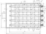
- FIG. 2 is a transverse sectional plan view for illustrating the manufacturing method for a glass article according to the first embodiment of the present invention.
- FIG. 3 is a transverse sectional plan view for illustrating a manufacturing method for a glass article according to a second embodiment of the present invention.
- a glass melting furnace 1 is configured as an electric melting furnace, and comprises a melting chamber 3 capable of accommodating a molten glass 2 .
- the glass melting furnace 1 is configured to heat a glass raw material 4 continuously supplied onto the molten glass 2 in the melting chamber 3 to successively melt the glass raw material 4 , and is also configured to cause the molten glass 2 to continuously flow outside the melting chamber 3 .
- the melting chamber 3 is formed of a refractory material, and has a rectangular sectional shape in plan view.
- the melting chamber 3 comprises: a front wall 3 a located at an upstream end and a rear wall 3 b located at a downstream end in a flowing direction D of the glass raw material 4 in the melting chamber 3 (hereinafter simply represented as “flowing direction D”); a pair of side walls 3 c and 3 d ; a ceiling wall 3 e ; and a bottom wall 3 f.
- Screw feeders 5 each serving as a supply unit configured to supply the glass raw material 4 are mounted to the front wall 3 a in parallel.
- five screw feeders 5 are arranged in parallel in a width direction perpendicular to the flowing direction D (hereinafter simply represented as “width direction”).
- Each of the screw feeders 5 is inserted into an opening 3 aa formed in the front wall 3 a without forming a gap.
- the amount of the glass raw material 4 to be supplied from each of the screw feeders 5 can be freely adjusted.
- a distance S 1 between central axes 5 a of screw feeders 5 and 5 , which are adjacent to each other along the width direction, is set so that, when an opening width W 1 of a distal end of each of the screw feeders 5 is used as a standard, the relationship of W 1 ⁇ S 1 ⁇ 10 ⁇ W 1 is satisfied.
- each of the “gap 6 ” and “gap 7 ” as used herein means a portion in which particles of the glass raw material 4 are melted and are not present on the surface of the molten glass 2 .
- the “portion in which the glass raw material 4 before melting is present” means a portion in which the particles of the glass raw material 4 are present on the surface of the molten glass 2 . A discrimination procedure therefor is described later.
- An outflow port 3 ba configured to cause the molten glass 2 to flow outside is formed on the rear wall 3 b.
- a plurality of sheet-shaped electrodes 8 each configured to heat the molten glass 2 through application of a current are mounted to each of the pair of side walls 3 c and 3 d under the state in which the plurality of electrodes 8 are immersed in the molten glass 2 .
- the pair of side walls 3 c and 3 d are located so as to be spaced apart from each other at a distance S 2 in the width direction.
- a plurality of rod-shaped electrodes 9 each configured to heat the molten glass 2 through application of a current are mounted to the bottom wall 3 f under the state in which the plurality of electrodes 9 are immersed in the molten glass 2 .
- energy (heat energy imparted to the molten glass 2 ) generated with the electrodes 8 and 9 may be adjusted by adjusting a voltage applied to the electrodes 8 and 9 .
- the glass raw materials 4 on the molten glass 2 are indirectly heated to be melted. With this, a fresh molten glass 2 is successively generated.
- Each of the plurality of rod-shaped electrodes 9 has a rod-shaped electrode 9 serving as its pair for application of a current, and the rod-shaped electrodes 9 forming a pair form an electrode pair 10 (in FIG. 2 , the rod-shaped electrodes 9 forming a pair are connected with a long dashed short dashed line).
- eight electrode pairs 10 are arranged along each of five expected flow passages P, and one rod-shaped electrode 9 and the other rod-shaped electrode 9 forming each pair of the eight electrode pairs 10 are arranged so as to be spaced apart from each other in the width direction.
- the one rod-shaped electrode 9 and the other rod-shaped electrode 9 are arranged so that the expected flow passage P passes between these electrodes. Further, in this embodiment, when the surface of the molten glass 2 is seen from the direction of plan view, the overall width of the glass raw material 4 supplied from each of the screw feeders 5 along the width direction is set to fall within the distance between the one rod-shaped electrode 9 and the other rod-shaped electrode 9 .
- a distance S 3 from the front wall 3 a to the electrode pair 10 closest to the front wall 3 a (hereinafter represented as “closest electrode pair 10 a ”) along the flowing direction D is set to be shorter than each of inter-electrode distances R 1 to R 7 between the electrode pairs 10 , which are adjacent to each other along the flowing direction D.
- the distances are set in that manner in order to avoid the stacking of the glass raw materials 4 in the vicinity of the screw feeders 5 , to thereby eliminate a risk in that the supply of a fresh glass raw material onto the molten glass 2 is inhibited by the glass raw materials 4 having been stacked on each other.
- the distance S 3 is preferably set within the range of from 100 mm to 2,500 mm.
- the inter-electrode distances R 1 to R 7 between the electrode pairs 10 may be the same or different from each other. Moreover, the inter-electrode distances R 1 to R 7 between the electrode pairs 10 are each preferably set within the range of from 100 mm to 1,500 mm.
- the following steps are performed.
- the composition of the glass article is not particularly limited, but the glass article to be manufactured in this embodiment is formed of alkali-free glass.
- the glass raw materials 4 are melted through heating only with the electrodes 8 and the electrodes 9 each immersed in the molten glass 2 in the melting chamber 3 .
- the molten glass 2 is heated only with the electrodes 8 and the electrodes 9 , and thus the glass raw materials 4 on the molten glass 2 are indirectly heated to be melted.
- the glass raw materials 4 are heated only with the electrodes 8 and the electrodes 9 after the continuous generation of the molten glass 2 is started.
- the glass raw materials 4 may be heated with, for example, burners (illustration thereof is omitted) mounted to the side walls 3 c and 3 d.
- the glass raw materials 4 supplied onto the molten glass 2 in the supply step are melted through heating only with the electrodes 8 and the electrodes 9 each immersed in the molten glass 2 in the melting step, and thus the meandering of the glass raw materials 4 on the molten glass 2 can be prevented.
- a width dimension W 2 of the gap can be maintained within an appropriate range. Therefore, according to this method, a state in which the glass raw materials 4 are dispersed on the molten glass 2 is achieved, and hence variation in quality of the molten glass 2 can be reduced.
- the meandering of the glass raw materials 4 on the molten glass 2 can be prevented, and hence inappropriate variation in molten state of the molten glass 2 can be suppressed. Further, when the gap 6 is formed, the removal of bubbles in the molten glass 2 can be promoted. As a result, the quality of a glass article to be manufactured can be improved.
- the atmosphere in the glass melting furnace 1 is dry as compared to the case of using combustion with a burner in combination. Therefore, moisture in the atmosphere can be prevented from being dissolved in the molten glass 2 , and thus the ⁇ -OH value of the glass article to be obtained can be reduced. With this, compaction at the time of heating the glass article to be obtained can be reduced, and a glass article suitable as a glass substrate for a display can be obtained.
- the width dimension W 2 of the gap 6 is preferably adjusted to 700 mm or less, and a width dimension W 3 of the gap 7 is preferably adjusted to 1,300 mm or less.
- the width dimension W 2 is preferably adjusted to 10 mm or more, and the width dimension W 3 is preferably adjusted to 100 mm or more.
- the width dimensions W 2 and W 3 may each be adjusted, for example, by changing at least one of: the supply amount of the glass raw material 4 by each of the screw feeders 5 ; the distance S 1 between the screw feeders 5 ; the opening width W 1 of each of the screw feeders 5 ; or energy generated with the electrodes 8 and 9 .
- the measurement methods for the width dimensions W 2 and W 3 are described later.
- a distance L 1 from the glass raw material 4 located on a most upstream side to the glass raw material 4 located on a most downstream side in the flowing direction D is preferably adjusted so that the relationship of L 1 ⁇ 0.65L 2 is satisfied.
- the “distance L 2 ” as used herein refers to the length of the surface of the molten glass 2 along the flowing direction D.
- the distance L 1 is preferably set to 0.95L 2 or less.
- the distance L 1 may be adjusted, for example, by changing at least one of: the supply amount of the glass raw material 4 by each of the screw feeders 5 ; or energy generated with the electrodes 8 and 9 .
- the distance L 1 may also be adjusted by changing the distribution of energy generated with the electrodes 9 in the flowing direction D. The measurement method for the distance L 1 is described later.
- the alkali-free glass has higher viscosity than alkali-containing glass. Therefore, when the alkali-free glass is melted, bubbles are liable to remain in the molten glass. That is, when the present invention is applied to the melting of the alkali-free glass, an improving effect on the quality of the glass article becomes remarkable. Accordingly, the glass article is preferably formed of the alkali-free glass.
- the “alkali-free glass” as used herein refers to glass substantially free of an alkali component (alkali metal oxide), and specifically refers to glass having a weight ratio of the alkali component of 3,000 ppm or less. In the present invention, the weight ratio of the alkali component is preferably 1,000 ppm or less, more preferably 500 ppm or less, most preferably 300 ppm or less.
- a manufacturing method for a glass article according to a second embodiment of the present invention is described below.
- the second embodiment only a difference from the first embodiment is described.
- the same reference symbols are assigned in the drawing referred to in the description of the second embodiment, and overlapping description thereof is omitted.
- the manufacturing method for a glass article according to the second embodiment differs from that of the first embodiment in that the one electrode 9 and the other electrode 9 forming each pair of the electrode pairs 10 are arranged so as to be spaced apart from each other not in the width direction but in the flowing direction D (in FIG. 3 , the electrodes 9 forming a pair are connected with a long dashed short dashed line). Also by the manufacturing method for a glass article according to the second embodiment, the same main action and effect as in the first embodiment can be obtained.
- the manufacturing method for a glass article according to the present invention is not limited to the modes described in the above-mentioned embodiments.
- the screw feeders 5 are used for supplying the glass raw materials 4 in each of the above-mentioned embodiments
- a pusher capable of pushing the glass raw materials 4 from an outside to an inside of the melting chamber 3 (front wall 3 a ) may be used.
- the five supply units are used, it is only required to use a plurality of supply units, and for example, two to six supply units may be used.
- electrodes having different shapes are used in combination by arranging the rod-shaped electrodes 9 and the sheet-shaped electrodes 8 in each of the above-mentioned embodiments, only electrodes having the same shape may be used. In addition, block-shaped electrodes may be used.
- the presence or absence of the glass raw material before melting is determined by the following procedure.
- An image is picked up with an image pickup unit (e.g., a camera) configured to collect the surface of the molten glass 2 (including the portion covered with the glass raw material 4 before melting) in the field of view.
- an image pickup unit e.g., a camera
- the image having been picked up may be corrected as described in WO 2013/100069 A1.
- the brightness serving as a standard in the item (2) of the above-mentioned procedure changes depending on the glass melting furnace, and hence is required to be set for every glass melting furnace.
- the brightness serving as a standard is set by the following procedure.
- An image is picked up with an image pickup unit configured to collect the surface of the molten glass 2 (including the portion covered with the glass raw material 4 before melting) in the field of view.
- the brightness at each collection position is obtained through use of the image of the item (a).
- a relationship between the number of particles of the glass raw material and the brightness is established based on the results obtained in the item (d), and the brightness at which the ratio of the area of the glass raw material remaining unmelted is 30% is determined and used as a standard.
- width dimensions W 2 and W 3 are each measured by the following procedure.
- the distance L 1 is measured by the following procedure.
- each glass substrate was formed of alkali-free glass in accordance with a glass substrate for a display (product name: OA-11) manufactured by Nippon Electric Glass Co., Ltd.
- the rate of occurrence of defects was calculated by dividing the number of glass substrates in which a defect was detected by the number of the glass substrates having been manufactured.
- the width W 2 of the gap was changed by changing the opening width W 1 of a distal end of the screw feeder 5 .
- a burner was additionally mounted to an upper portion of the melting chamber, and the glass raw materials were melted through heating with the burner in combination with the electrodes.
- the test conditions and test results are shown in Table 1.
- the symbol “ ⁇ ” in the “Formation of gap” of Table 1 represents the case in which the glass raw materials supplied from the plurality of screw feeders extend along the flowing direction without joining with each other in the course of their flowing, and thus the gap is formed.
- the symbol “x” in the “Formation of gap” of Table 1 represents the case in which the glass raw materials supplied from the plurality of screw feeders meander to join with each other in the course of their flowing, and thus the gap is not formed.
- the symbol “ ⁇ ” represents the case in which the rate of occurrence of defects is low, and a satisfactory result is obtained
- the symbol “x” represents the case in which the rate of occurrence of defects is high, and an unacceptable result is obtained.
- the quality of the glass article can be improved by the manufacturing method for a glass article according to the present invention.
Landscapes
- Chemical & Material Sciences (AREA)
- Engineering & Computer Science (AREA)
- Materials Engineering (AREA)
- Organic Chemistry (AREA)
- Chemical Kinetics & Catalysis (AREA)
- Electrochemistry (AREA)
- Glass Melting And Manufacturing (AREA)
- Glass Compositions (AREA)
Abstract
Description
- Patent Literature 1: JP 5282619 B2
(c) The collected samples are each poured into a mold and cooled, followed by being cut, to thereby produce a plurality of samples.
(d) With respect to an arbitrary region measuring 10 mm by 10 mm on a cut surface of each sample, the ratio of the area of the glass raw material remaining unmelted is calculated. In addition, the brightness at each collection position is obtained through use of the image of the item (a).
(e) A relationship between the number of particles of the glass raw material and the brightness is established based on the results obtained in the item (d), and the brightness at which the ratio of the area of the glass raw material remaining unmelted is 30% is determined and used as a standard.
(b) Through use of the image of the item (a), a portion at which the width of the portion in which the glass
(b) Through use of the image of the item (a), with regard to the portion in which the glass
| TABLE 1 | ||||||
| Rate of | ||||||
| Heating | Formation | Width W2 | Distance | occurrence | ||
| conditions | of gap | of gap | L1 | of defects | ||
| Division | Example 1 | Only with | ∘ | 10 mm | 0.8L2 | ∘ |
| electrode | ||||||
| Example 2 | Only with | ∘ | 100 mm | 0.8L2 | ∘ | |
| electrode | ||||||
| Example 3 | Only with | ∘ | 300 mm | 0.8L2 | ∘ | |
| electrode | ||||||
| Example 4 | Only with | ∘ | 600 mm | 0.8L2 | ∘ | |
| electrode | ||||||
| Comparative | Combination | x | — | 0.5L2 | x | |
| Example | with burner | |||||
- 1 glass melting furnace
- 2 molten glass
- 3 melting chamber
- 3 a front wall
- 3 b rear wall
- 3 c side wall
- 3 d side wall
- 3 e ceiling wall
- 3 f bottom wall
- 4 glass raw material
- 5 screw feeder
- 6 gap
- 8 electrode
- 9 electrode
- 10 electrode pair
- 10 a closest electrode pair
- P expected flow passage
- R1 to R7 inter-electrode distance
- S3 distance
Claims (3)
Applications Claiming Priority (4)
| Application Number | Priority Date | Filing Date | Title |
|---|---|---|---|
| JP2017175770A JP6975401B2 (en) | 2017-09-13 | 2017-09-13 | Manufacturing method of glass articles |
| JP2017-175770 | 2017-09-13 | ||
| JPJP2017-175770 | 2017-09-13 | ||
| PCT/JP2018/030575 WO2019054126A1 (en) | 2017-09-13 | 2018-08-17 | Glass article manufacturing method |
Publications (2)
| Publication Number | Publication Date |
|---|---|
| US20210122657A1 US20210122657A1 (en) | 2021-04-29 |
| US11225428B2 true US11225428B2 (en) | 2022-01-18 |
Family
ID=65723632
Family Applications (1)
| Application Number | Title | Priority Date | Filing Date |
|---|---|---|---|
| US16/645,054 Active US11225428B2 (en) | 2017-09-13 | 2018-08-17 | Glass article manufacturing method |
Country Status (6)
| Country | Link |
|---|---|
| US (1) | US11225428B2 (en) |
| JP (1) | JP6975401B2 (en) |
| KR (1) | KR102553505B1 (en) |
| CN (1) | CN111051254B (en) |
| TW (1) | TWI778123B (en) |
| WO (1) | WO2019054126A1 (en) |
Families Citing this family (2)
| Publication number | Priority date | Publication date | Assignee | Title |
|---|---|---|---|---|
| KR102894088B1 (en) | 2020-04-29 | 2025-12-01 | 주식회사 엘지에너지솔루션 | Battery module and battery pack including the same |
| JP2024047915A (en) * | 2022-09-27 | 2024-04-08 | Agc株式会社 | Glass melting apparatus and glass manufacturing method |
Citations (13)
| Publication number | Priority date | Publication date | Assignee | Title |
|---|---|---|---|---|
| US3885945A (en) | 1974-03-20 | 1975-05-27 | Owens Corning Fiberglass Corp | Method of and apparatus for electrically heating molten glass |
| US3961126A (en) * | 1974-06-03 | 1976-06-01 | Owens-Corning Fiberglas Corporation | Apparatus and method for increasing electric power in an electric glass-melting furnace |
| JPS5926931A (en) | 1982-07-30 | 1984-02-13 | Nippon Electric Glass Co Ltd | Electrical smelting method |
| US4432780A (en) * | 1982-08-27 | 1984-02-21 | Owens-Corning Fiberglas Corporation | Glass fiber scrap reclamation |
| US4531218A (en) * | 1983-06-17 | 1985-07-23 | Owens-Corning Fiberglas Corporation | Glass melting furnace |
| JPH01164735A (en) | 1987-12-18 | 1989-06-28 | Nippon Sheet Glass Co Ltd | Method for melting glass |
| JPH05282619A (en) | 1992-03-31 | 1993-10-29 | Sankyo Seiki Mfg Co Ltd | Magnetic head |
| JPH09208228A (en) | 1996-01-31 | 1997-08-12 | Toshiba Glass Co Ltd | Electrically-heated glass melting furnace |
| US6085551A (en) * | 1997-03-14 | 2000-07-11 | Beteiligungen Sorg Gmbh & Co. Kg | Method and apparatus for manufacturing high melting point glasses with volatile components |
| JP2003183031A (en) | 2001-12-18 | 2003-07-03 | Nippon Electric Glass Co Ltd | Electric melting furnace for manufacturing glass fiber and method of melting glass for glass fiber |
| JP2004091232A (en) | 2002-08-30 | 2004-03-25 | Nippon Sheet Glass Co Ltd | Method for recycling glass waste and melting furnace used therefor |
| US20090044567A1 (en) * | 2007-08-16 | 2009-02-19 | William Weston Johnson | Method and apparatus for controlling the level of a molten material in a glass manufacturing system |
| JP5282619B2 (en) | 2009-03-25 | 2013-09-04 | 日本電気硝子株式会社 | Glass melting furnace |
Family Cites Families (8)
| Publication number | Priority date | Publication date | Assignee | Title |
|---|---|---|---|---|
| JPH0421795Y2 (en) * | 1988-05-09 | 1992-05-19 | ||
| GB9206928D0 (en) * | 1992-03-30 | 1992-05-13 | Pilkington Plc | Glass melting |
| JPH11100214A (en) * | 1997-09-26 | 1999-04-13 | Nippon Electric Glass Co Ltd | Glass melting furnace |
| FR2991759B1 (en) * | 2012-06-12 | 2014-06-20 | Saint Gobain Isover | GLASS FUSION INSTALLATION |
| JP5864690B2 (en) * | 2013-09-30 | 2016-02-17 | AvanStrate株式会社 | Glass substrate manufacturing method, glass substrate manufacturing apparatus, and molten glass processing apparatus |
| US9611163B2 (en) * | 2014-03-05 | 2017-04-04 | Owens-Brockway Glass Container Inc. | Process and apparatus for refining molten glass |
| TW201711967A (en) * | 2015-08-26 | 2017-04-01 | 美商.康寧公司 | Glass melting system and method for increased homogeneity |
| JP2017065965A (en) * | 2015-09-30 | 2017-04-06 | Hoya株式会社 | Device for supplying glass raw material, apparatus for manufacturing glass raw material melt, method for supplying glass raw material, method for manufacturing glass and method for manufacturing glass component |
-
2017
- 2017-09-13 JP JP2017175770A patent/JP6975401B2/en active Active
-
2018
- 2018-08-17 WO PCT/JP2018/030575 patent/WO2019054126A1/en not_active Ceased
- 2018-08-17 CN CN201880056597.8A patent/CN111051254B/en active Active
- 2018-08-17 KR KR1020197037634A patent/KR102553505B1/en active Active
- 2018-08-17 US US16/645,054 patent/US11225428B2/en active Active
- 2018-09-04 TW TW107130903A patent/TWI778123B/en active
Patent Citations (14)
| Publication number | Priority date | Publication date | Assignee | Title |
|---|---|---|---|---|
| US3885945A (en) | 1974-03-20 | 1975-05-27 | Owens Corning Fiberglass Corp | Method of and apparatus for electrically heating molten glass |
| JPS50133214A (en) | 1974-03-20 | 1975-10-22 | ||
| US3961126A (en) * | 1974-06-03 | 1976-06-01 | Owens-Corning Fiberglas Corporation | Apparatus and method for increasing electric power in an electric glass-melting furnace |
| JPS5926931A (en) | 1982-07-30 | 1984-02-13 | Nippon Electric Glass Co Ltd | Electrical smelting method |
| US4432780A (en) * | 1982-08-27 | 1984-02-21 | Owens-Corning Fiberglas Corporation | Glass fiber scrap reclamation |
| US4531218A (en) * | 1983-06-17 | 1985-07-23 | Owens-Corning Fiberglas Corporation | Glass melting furnace |
| JPH01164735A (en) | 1987-12-18 | 1989-06-28 | Nippon Sheet Glass Co Ltd | Method for melting glass |
| JPH05282619A (en) | 1992-03-31 | 1993-10-29 | Sankyo Seiki Mfg Co Ltd | Magnetic head |
| JPH09208228A (en) | 1996-01-31 | 1997-08-12 | Toshiba Glass Co Ltd | Electrically-heated glass melting furnace |
| US6085551A (en) * | 1997-03-14 | 2000-07-11 | Beteiligungen Sorg Gmbh & Co. Kg | Method and apparatus for manufacturing high melting point glasses with volatile components |
| JP2003183031A (en) | 2001-12-18 | 2003-07-03 | Nippon Electric Glass Co Ltd | Electric melting furnace for manufacturing glass fiber and method of melting glass for glass fiber |
| JP2004091232A (en) | 2002-08-30 | 2004-03-25 | Nippon Sheet Glass Co Ltd | Method for recycling glass waste and melting furnace used therefor |
| US20090044567A1 (en) * | 2007-08-16 | 2009-02-19 | William Weston Johnson | Method and apparatus for controlling the level of a molten material in a glass manufacturing system |
| JP5282619B2 (en) | 2009-03-25 | 2013-09-04 | 日本電気硝子株式会社 | Glass melting furnace |
Non-Patent Citations (3)
| Title |
|---|
| International Preliminary Report on Patentability and Written Opinion of the International Searching Authority dated Mar. 17, 2020 in International (PCT) Application No. PCT/JP2018/030575. |
| International Search Report dated Nov. 13, 2018 in International (PCT) Application No. PCT/JP2018/030575. |
| Office Action dated Oct. 15, 2021 in corresponding Chinese Application No. 201880056597.8 with English translation of Search Report. |
Also Published As
| Publication number | Publication date |
|---|---|
| US20210122657A1 (en) | 2021-04-29 |
| JP2019052052A (en) | 2019-04-04 |
| CN111051254B (en) | 2022-08-02 |
| TWI778123B (en) | 2022-09-21 |
| CN111051254A (en) | 2020-04-21 |
| TW201920006A (en) | 2019-06-01 |
| KR102553505B1 (en) | 2023-07-10 |
| KR20200052249A (en) | 2020-05-14 |
| JP6975401B2 (en) | 2021-12-01 |
| WO2019054126A1 (en) | 2019-03-21 |
Similar Documents
| Publication | Publication Date | Title |
|---|---|---|
| US11613487B2 (en) | Method for producing glass article | |
| US20110197633A1 (en) | Method for manufacturing glass film | |
| TWI840469B (en) | Glass manufacturing apparatus and methods | |
| US11225428B2 (en) | Glass article manufacturing method | |
| TWI787409B (en) | Method for manufacturing glass objects | |
| KR101971755B1 (en) | Apparatus for producing molten glass, method for producing molten glass, and method for producing plate glass using said apparatus and method | |
| KR101798292B1 (en) | Method for making glass substrate for display | |
| US11530152B2 (en) | Method for manufacturing glass article, and melting furnace | |
| US20160122222A1 (en) | Feeder | |
| KR102196157B1 (en) | Manufacturing method for molten glass and manufacturing method for sheet glass using same | |
| JP7090844B2 (en) | Manufacturing method of glass articles and glass substrate group | |
| JP7374186B2 (en) | Apparatus and method for mitigating electrochemical attack of precious metal components in glass making processes | |
| JP7610796B2 (en) | Method for manufacturing glass articles | |
| CN117776492A (en) | Glass melting method and method of manufacturing glass articles | |
| KR20230135043A (en) | Method of manufacturing glass articles |
Legal Events
| Date | Code | Title | Description |
|---|---|---|---|
| AS | Assignment |
Owner name: NIPPON ELECTRIC GLASS CO., LTD., JAPAN Free format text: ASSIGNMENT OF ASSIGNORS INTEREST;ASSIGNORS:TSUKAMOTO, AKIYUKI;TENYAMA, KAZUYUKI;SIGNING DATES FROM 20200110 TO 20200115;REEL/FRAME:052037/0558 |
|
| FEPP | Fee payment procedure |
Free format text: ENTITY STATUS SET TO UNDISCOUNTED (ORIGINAL EVENT CODE: BIG.); ENTITY STATUS OF PATENT OWNER: LARGE ENTITY |
|
| STPP | Information on status: patent application and granting procedure in general |
Free format text: FINAL REJECTION MAILED |
|
| STPP | Information on status: patent application and granting procedure in general |
Free format text: RESPONSE AFTER FINAL ACTION FORWARDED TO EXAMINER |
|
| STPP | Information on status: patent application and granting procedure in general |
Free format text: NOTICE OF ALLOWANCE MAILED -- APPLICATION RECEIVED IN OFFICE OF PUBLICATIONS |
|
| STPP | Information on status: patent application and granting procedure in general |
Free format text: PUBLICATIONS -- ISSUE FEE PAYMENT VERIFIED |
|
| STCF | Information on status: patent grant |
Free format text: PATENTED CASE |
|
| MAFP | Maintenance fee payment |
Free format text: PAYMENT OF MAINTENANCE FEE, 4TH YEAR, LARGE ENTITY (ORIGINAL EVENT CODE: M1551); ENTITY STATUS OF PATENT OWNER: LARGE ENTITY Year of fee payment: 4 |