US11224788B2 - Vibration-damping end caps for ball bats - Google Patents
Vibration-damping end caps for ball bats Download PDFInfo
- Publication number
- US11224788B2 US11224788B2 US16/667,818 US201916667818A US11224788B2 US 11224788 B2 US11224788 B2 US 11224788B2 US 201916667818 A US201916667818 A US 201916667818A US 11224788 B2 US11224788 B2 US 11224788B2
- Authority
- US
- United States
- Prior art keywords
- sprung
- base portion
- bat
- mass
- mass portion
- Prior art date
- Legal status (The legal status is an assumption and is not a legal conclusion. Google has not performed a legal analysis and makes no representation as to the accuracy of the status listed.)
- Active
Links
Images


Classifications
-
- A—HUMAN NECESSITIES
- A63—SPORTS; GAMES; AMUSEMENTS
- A63B—APPARATUS FOR PHYSICAL TRAINING, GYMNASTICS, SWIMMING, CLIMBING, OR FENCING; BALL GAMES; TRAINING EQUIPMENT
- A63B60/00—Details or accessories of golf clubs, bats, rackets or the like
- A63B60/54—Details or accessories of golf clubs, bats, rackets or the like with means for damping vibrations
-
- A—HUMAN NECESSITIES
- A63—SPORTS; GAMES; AMUSEMENTS
- A63B—APPARATUS FOR PHYSICAL TRAINING, GYMNASTICS, SWIMMING, CLIMBING, OR FENCING; BALL GAMES; TRAINING EQUIPMENT
- A63B59/00—Bats, rackets, or the like, not covered by groups A63B49/00 - A63B57/00
- A63B59/50—Substantially rod-shaped bats for hitting a ball in the air, e.g. for baseball
- A63B59/56—Substantially rod-shaped bats for hitting a ball in the air, e.g. for baseball characterised by the head
-
- A—HUMAN NECESSITIES
- A63—SPORTS; GAMES; AMUSEMENTS
- A63B—APPARATUS FOR PHYSICAL TRAINING, GYMNASTICS, SWIMMING, CLIMBING, OR FENCING; BALL GAMES; TRAINING EQUIPMENT
- A63B60/00—Details or accessories of golf clubs, bats, rackets or the like
- A63B60/06—Handles
- A63B60/16—Caps; Ferrules
-
- A—HUMAN NECESSITIES
- A63—SPORTS; GAMES; AMUSEMENTS
- A63B—APPARATUS FOR PHYSICAL TRAINING, GYMNASTICS, SWIMMING, CLIMBING, OR FENCING; BALL GAMES; TRAINING EQUIPMENT
- A63B2102/00—Application of clubs, bats, rackets or the like to the sporting activity ; particular sports involving the use of balls and clubs, bats, rackets, or the like
- A63B2102/18—Baseball, rounders or similar games
- A63B2102/182—Softball
-
- A—HUMAN NECESSITIES
- A63—SPORTS; GAMES; AMUSEMENTS
- A63B—APPARATUS FOR PHYSICAL TRAINING, GYMNASTICS, SWIMMING, CLIMBING, OR FENCING; BALL GAMES; TRAINING EQUIPMENT
- A63B2209/00—Characteristics of used materials
Definitions
- a ball bat such as a baseball or softball bat
- the impact causes vibration in the bat that batters may experience as a painful sting in their hands. Vibration may be more severe when the ball impacts the bat away from a center of percussion in the barrel (sometimes referred to as the “sweet spot”). If the vibration is especially severe, it may injure a batter.
- batters may wear padded gloves or use a thick cushioned grip on the bat handle. But some padded gloves and thick grips reduce tactile gnosis, and a thick grip may add unnecessary weight to a ball bat. It is desirable to dampen vibrations in a ball bat without reducing tactile gnosis and without adding unnecessary weight.
- Representative embodiments of the present technology include an end-cap assembly configured to be attached to a distal end of a barrel of a ball bat.
- the end-cap assembly includes a sprung-mass portion, a base portion, and one or more flexible members connecting the sprung-mass portion to the base portion.
- the sprung-mass portion is movable relative to the base portion along one or more directions, such as one or more directions transverse to the longitudinal axis of the ball bat or along the longitudinal axis of the bat.
- the base portion is configured to be attached to the distal end of the barrel.
- a ball bat may include a handle with a knob, a barrel attached to the handle, and an end-cap assembly attached to the barrel, the end-cap assembly including a sprung-mass portion, a base portion, and one or more flexible members connecting the sprung-mass portion to the base portion to allow the sprung-mass portion to move relative to the distal end of the ball bat or the base portion.
- the sprung-mass portion and the base portion are connected to each other by only the one or more flexible members.
- the one or more flexible members include a partial or complete ring of flexible material positioned around the sprung-mass portion and between the sprung-mass portion and the base portion.
- the one or more flexible members include a plurality of ribs extending radially inwardly from the base portion.
- the one or more flexible members may extend longitudinally between the base portion and the sprung-mass portion.
- the sprung-mass portion includes a hub, and the one or more flexible members includes a plurality of serpentine ribs extending between the hub and the base portion.
- the sprung-mass portion is spaced apart from the base portion along the longitudinal axis of the bat to form a gap between the sprung-mass portion and the base portion.
- an end-cap assembly includes a sprung-mass portion and one or more flexible members extending from the sprung-mass portion to connect the end-cap assembly to the barrel of a ball bat.
- the one or more flexible members may enable movement of the sprung-mass portion relative to the barrel of the ball bat.
- FIG. 1 illustrates a ball bat that may include an end-cap assembly according to embodiments of the present technology.
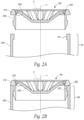
- FIGS. 2A and 2B illustrate cross-sectional views of a distal end of a ball bat and an end-cap assembly configured in accordance with embodiments of the present technology.
- FIG. 2C illustrates a top view of the end-cap assembly shown in FIGS. 2A and 2B .
- FIG. 2D illustrates a perspective cross-sectional view of an end-cap assembly configured in accordance with an embodiment of the present technology.
- FIGS. 3A, 3B, and 3C illustrate a top view, a bottom view, and a side cross-sectional view, respectively, of an end-cap assembly configured in accordance with an embodiment of the present technology.
- FIGS. 4A-4E illustrate a top view, a side view, a bottom view, a bottom perspective view, and a side cross-sectional view, respectively, of an end-cap assembly configured in accordance with an embodiment of the present technology.
- FIGS. 5A-5C illustrate a side perspective view, a bottom perspective view, and a side cross-sectional view, respectively, of an end-cap assembly configured in accordance with an embodiment of the present technology.
- FIGS. 6A-6D illustrate a top view, a side view, a side cross-sectional view, and an exploded side cross-sectional view, respectively, of an end-cap assembly configured in accordance with an embodiment of the present technology.
- FIGS. 7A, 7B, and 7C illustrate a perspective exploded view, a perspective cross-sectional assembled view, and a schematic partially-assembled view, respectively, of an end-cap assembly configured in accordance with an embodiment of the present technology.
- the present technology is directed to vibration-damping end caps for ball bats, and associated systems and methods.
- Various embodiments of the technology will now be described. The following description provides specific details for a thorough understanding and enabling description of these embodiments. One skilled in the art will understand, however, that the invention may be practiced without many of these details. Additionally, some well-known structures or functions, such as those common to ball bats, may not be shown or described in detail so as to avoid unnecessarily obscuring the relevant description of the various embodiments. Accordingly, embodiments of the present technology may include additional elements or exclude some of the elements described below with reference to FIGS. 1-7C , which illustrate examples of the technology.
- FIG. 1 illustrates a ball bat 100 extending along a longitudinal axis x and having a barrel 110 attached to a handle 120 .
- a radial axis y is also illustrated and is understood to be any radial direction perpendicular to the x-axis.
- the handle 120 may include a knob 140 , while an end-cap assembly 150 may be retained on or within the bat 100 at a distal end 160 opposite the knob 140 and the handle 120 .
- the end-cap assembly 150 may be attached to the distal end 160 , for example, and it may also generally cover the distal end 160 or close off an open end of the barrel 110 at the distal end 160 .
- the bat 100 may have any suitable dimensions.
- the bat 100 may have an overall length of 20 to 40 inches, or 26 to 34 inches.
- the overall barrel diameter may be 2.0 to 3.0 inches, or 2.25 to 2.75 inches.
- typical ball bats may have diameters of 2.25, 2.625, or 2.75 inches.
- Bats having various combinations of these overall lengths and barrel diameters, or any other suitable dimensions, are contemplated herein. Bats suitable for use in baseball or softball or other similar activities are contemplated herein.
- the specific preferred combination of bat dimensions is generally dictated by the user of the bat 100 , and may vary greatly between users.
- FIGS. 2A and 2B illustrate cross-sectional views of the distal end 160 of the ball bat and an end-cap assembly 150 configured in accordance with embodiments of the present technology.
- FIG. 2A is an exploded view illustrating the end-cap assembly 150 and the distal end 160 of a ball bat.
- FIG. 2B is an assembled view illustrating the end-cap assembly 150 attached to the distal end 160 of the ball bat.
- end-cap assemblies configured in accordance with embodiments of the present technology include a sprung-mass mechanism that suspends all or part of the mass of the end-cap assembly on or in the distal end 160 of the ball bat.
- an end-cap assembly 150 may include a sprung-mass portion 200 connected to a base portion 210 via a flexible member 220 (or one or more flexible members 220 , in accordance with embodiments of the present technology).
- the one or more flexible members may also provide a force or forces that tend to bias the sprung-mass portion to be centered (such as concentric) with the base portion.
- the base portion 210 (or the end-cap assembly 150 as a whole) may be molded, bonded, pressed, or otherwise locked in the distal end 160 of the bat such that it stays attached to the bat during use.
- a ridge or lip 230 protruding inwardly and extending around all or part of the wall 240 of the bat engages a corresponding groove or recess 250 circumscribing the base portion 210 of the end-cap assembly 150 .
- the base portion 210 functions as a retention ring to hold the remainder of the end-cap assembly 150 in or on the distal end 160 of the bat.
- the base portion 210 supports and suspends the sprung-mass portion 200 via the flexible member 220 .
- the sprung-mass portion 200 may have any suitable shape, for example, a cone, a disk, or any other configuration having mass.
- the sprung-mass portion 200 is concentrically positioned within the base portion 210 , separated from the base portion 210 by the flexible member 220 .
- the flexible member 220 includes a partial or complete ring of flexible material (such as an elastomeric material) around the sprung-mass portion 200 .
- the flexible member 220 may include any material or shape suitable for movably suspending the sprung-mass portion 200 relative to the base portion 210 .
- a sprung-mass portion such as the sprung-mass portion 200 shown in FIGS. 2A and 2B , may be movable relative to a base portion, such as the base portion 210 shown in FIGS. 2A and 2B , via a flexible member 220 (or one or more flexible members).
- the sprung-mass portion of an end-cap assembly may move relative to the distal end 160 of the ball bat.
- the sprung-mass portion may move along the longitudinal axis x (see FIGS. 1 and 2B ), transverse to the longitudinal axis x (such as perpendicular to the longitudinal axis x along the radial axis y, see FIGS. 1 and 2B ), along a direction that includes components of motion along the longitudinal axis and transverse to the longitudinal axis, or along other directions relative to the distal end 160 , such as general side-to-side movement relative to the distal end 160 (or relative to a base portion if a base portion is implemented).
- the sprung-mass portion may be generally constrained along the longitudinal axis x (for example, to minimize movement of the sprung-mass portion along the longitudinal axis x) but allowed to move transversely to the longitudinal axis x, such as along the radial axis y.
- the impulse force from a bat-ball collision may be in the range of thousands of pounds for approximately one or two milliseconds.
- the force of the collision with the ball causes the bat to change speed during the batter's swing as the ball compresses and changes direction.
- the bat may change speed for a short period of time, such as 0.0007 seconds, by a measure of approximately 300 g (g-force), or by other quantities (which may be large).
- the sprung-mass portion of the end-cap assembly When the product of the mass of the sprung-mass portion of the end-cap assembly and the change in speed of the bat is greater than the spring force suspending the sprung-mass portion (provided by, for example, one or more flexible members, such as the flexible member 220 ), the sprung-mass portion of the end-cap assembly will move relative to the distal end 160 . The motion of the sprung-mass portion will lag behind the motion of the ball bat (or the sprung-mass portion may stay generally stationary relative to the ball bat) until the product of the mass of the sprung-mass portion of the end-cap assembly and the change in speed of the bat is less than or equal to the spring force suspending the sprung-mass portion.
- the sprung-mass portion will oscillate relative to the bat depending on the characteristics of the material suspending the sprung-mass portion, which will dissipate some of the vibrational energy (for example, in the form of heat) from the impact, until the sprung-mass portion returns to its original resting position. In other words, the sprung-mass portion moves relative to the bat to dampen shock and vibration from the impact between the bat and the ball.
- FIG. 2C illustrates a top view of the end-cap assembly 150 shown in FIGS. 2A and 2B .
- the flexible member 220 may be formed by overmolding an elastomeric material onto the sprung-mass portion 200 and the base portion 210 , thereby connecting the sprung-mass portion 200 to the base portion 210 via the flexible member 220 .
- the flexible member 220 may have a Shore hardness rating of approximately 70A or less (such as Shore 45A), or the flexible member 220 may have other hardness ratings, depending on, for example, the mass of the sprung-mass portion 200 and the characteristics of vibration sought to be reduced.
- the flexible member 220 may be harder, such as approximately Shore 60D.
- FIG. 2D illustrates a perspective cross-sectional view of an end-cap assembly 260 configured in accordance with another embodiment of the present technology.
- the end-cap assembly 260 may be generally similar to the end-cap assembly 150 illustrated in FIGS. 2A-2C , but the flexible member 270 may include a bellows shape 280 to further reduce stress and stiffness at the junction between the sprung-mass portion 200 and the base portion 210 .
- the junction between the sprung-mass portion 200 and the base portion 210 including the flexible member 270 , may take other forms or shapes suitable for facilitating relative movement between the sprung-mass portion 200 and the base portion 210 .
- End-cap assemblies configured in accordance with embodiments of the present technology (including assemblies described herein) may be formed as unitized structures in which the sprung-mass portion (such as the sprung-mass portion 200 , or other sprung-mass portions), the base portion (such as the base portion 210 , or other base portions, if a base portion is implemented), and the flexible member (such as the flexible member 220 or the flexible member 270 , or other flexible members) are integrally formed.
- end-cap assemblies may be formed from separate components brought together.
- end-cap assemblies configured in accordance with embodiments of the present technology are disclosed herein, however, the present technology generally contemplates any end-cap assembly in which a sprung mass is suspended relative to (such as in or on) a distal end of a ball bat by one or more flexible members that facilitate movement of the sprung mass relative to the distal end of the bat.
- End-cap assemblies configured in accordance with embodiments of the present technology may be formed such that the mass of the sprung-mass portion (such as the sprung-mass portion 200 ) is at least 5 percent of the overall mass of the end-cap assembly or up to 99 percent (such as 95 percent or more) of the overall mass of the end-cap assembly, or other percentages of the overall mass of the end-cap assembly.
- end-cap assemblies may weigh approximately 0.8 ounces (26.7 grams), while the sprung-mass portion may weigh between 0.04 ounces and 0.79 ounces.
- end-cap assemblies may weigh other amounts, and the sprung-mass portions may weigh other amounts.
- FIGS. 3A, 3B, and 3C illustrate a top view, a bottom view, and a side cross-sectional view, respectively, of an end-cap assembly 300 configured in accordance with another embodiment of the present technology.
- a base portion 310 may be configured to be mounted or otherwise restrained in or on the distal end 160 of a bat in a manner similar to the base portion 210 described above with regard to FIGS. 2A-2D .
- the base portion 310 supports a sprung-mass portion 320 that is suspended from the base portion 310 with one or more flexible members 330 .
- the flexible members 330 may be in the form of ribs extending radially inwardly from the base portion 310 and—in some embodiments—longitudinally (along the bat's x-axis) between the base portion 310 and the sprung-mass portion 320 .
- a gap 340 is provided between the base portion 310 and the sprung-mass portion 320 , such that the base portion 310 and the sprung-mass portion 320 are spaced apart from each other along the longitudinal axis of the bat (which is equivalent to the longitudinal axis of the end-cap assembly) and connected to each other only by the flexible members 330 .
- the sprung-mass portion 320 is generally isolated from the base portion 310 so that the sprung-mass portion 320 can move relative to the base portion 310 and the remainder of the ball bat.
- the sprung-mass portion 320 may move in a similar manner as the sprung-mass portion 200 described above for FIGS. 2A-2D to reduce vibration.
- the flexible members 330 or the sprung-mass portion 320 may be formed with a material having a hardness rating that is less than a hardness rating of a material forming the base portion 310 .
- the flexible members 330 may be soft and flexible enough to allow the sprung-mass portion 320 to compress toward the base portion 310 during installation of the end-cap assembly 300 (end-cap assemblies may be pressed into the distal end of the bat).
- a tool or stiffening element may be positioned in or near the gap 340 to prevent damage to the flexible members 330 during installation.
- FIGS. 4A-4E illustrate a top view, a side view, a bottom view, a bottom perspective view, and a side cross-sectional view, respectively, of an end-cap assembly 400 configured in accordance with another embodiment of the present technology.
- a base portion 410 may be configured to be mounted or otherwise restrained in or on the distal end 160 of a bat in a manner similar to the base portions described above.
- the base portion 410 supports a sprung-mass portion 420 that is flexibly suspended relative to the base portion 410 with one or more flexible members 430 .
- the sprung-mass portion 420 may include a hub 440 extending toward the knob of the ball bat and positioned concentrically within the base portion 410 .
- the flexible members 430 may be in the form of curved ribs (such as serpentine ribs) that curve inwardly from the base portion 410 to the hub 440 .
- the flexible members 430 allow the sprung-mass portion 420 to move relative to other components of the end-cap assembly or the distal end (e.g., transverse to the bat's longitudinal x-axis, such as perpendicular to the x-axis, along the radial y-axis, or other motion).
- the flexible members 430 may be sufficiently stiff to limit axial movement along the bat's longitudinal axis x.
- a gap 450 may be located between the base portion 410 and the sprung-mass portion 420 , such that the base portion 410 and the sprung-mass portion 420 are spaced apart from each other along the longitudinal axis x of the bat and connected to each other only by the flexible members 430 .
- the gap 450 may be minimal to limit movement of the sprung-mass portion 420 along the longitudinal x-axis of the bat (while still allowing movement transverse to the longitudinal x-axis, such as radial movement along the y-axis or other side-to-side movement), which in turn may help prevent overstressing the flexible members 430 during installation of the end-cap assembly 400 into the distal end 160 of the bat.
- one or more optional axial support nubs 460 positioned on the base portion 410 and extending along the longitudinal x-axis of the bat toward the sprung-mass portion 420 may partially fill portions of the gap 450 to further limit movement of the sprung-mass portion 420 along the longitudinal x-axis.
- similar nubs 460 may be implemented in the gap 340 described above with regard to FIGS. 3A-3C .
- FIGS. 5A-5C illustrate a side perspective view, a bottom perspective view, and a side cross-sectional view, respectively, of an end-cap assembly 500 configured in accordance with another embodiment of the present technology.
- a sprung-mass portion 510 may include a hub 520 (which may be similar to the hub 440 described above with regard to FIGS. 4A-4E ) extending toward the knob end of a bat.
- One or more flexible members 530 (such as a plurality of flexible members 530 ) may extend outwardly from the hub 520 .
- the flexible members 530 may include curved ribs (such as serpentine ribs) extending from the hub 520 as shown in FIGS.
- the flexible members 530 may hold the end-cap assembly 500 in the distal end 160 of the bat by extending underneath, and wider than, an opening created by the lip 230 of the wall 240 of the bat.
- the flexible members 530 enable movement of the sprung-mass portion 510 relative to the distal end 160 , for example, movement transverse (such as perpendicular) to the longitudinal x-axis of the bat (or other movement), to provide vibration damping to the bat in a manner similar to other sprung-mass portions described herein.
- the flexible members 530 may be bonded, adhered, mechanically fastened, or otherwise attached to the bat, with or without the implementation of a lip or groove in the ball bat. Accordingly, embodiments of the present technology include end-cap assemblies that do not require a base portion. In some embodiments, the sprung mass may constitute nearly the entire mass of the end-cap assembly 500 .
- FIGS. 6A-6D illustrate a top view, a side view, a side cross-sectional view, and an exploded side cross-sectional view, respectively, of an end-cap assembly 600 configured in accordance with another embodiment of the present technology, in which the assembly includes separate pieces assembled together.
- a base portion 610 may be configured to be mounted or otherwise restrained in or on the distal end 160 of a bat in a manner similar to the base portions described above.
- a sprung-mass portion 620 may include a connecting portion 630 positioned to extend concentrically into the base portion 610 .
- a retention washer 640 may restrain (such as lock) the connecting portion 630 of the sprung-mass portion 620 to a corresponding connecting portion 650 of the base portion 610 to hold the sprung-mass portion 620 in the base portion 610 while allowing movement of the sprung-mass portion 620 relative to the base portion 610 (in a manner similar to other sprung-mass portions described herein).
- the connecting portion 630 may be cylindrical and it may include one or more beveled edges or lips for engaging the retention washer 640 .
- One or more flexible members such as a flexible member 660 may be positioned between the connecting portion 630 of the sprung-mass portion 620 and the connecting portion 650 of the base portion 610 to enable dampened movement between the sprung-mass portion 620 and the base portion 610 .
- the one or more flexible members may also provide a force or forces that tend to bias the sprung-mass portion 620 to be centered and concentric with the base portion 610 .
- the flexible member 660 may include an O-ring (made of foam or another suitable elastomeric material) as shown in FIGS.
- the flexible member 660 may include a J-spring, one or more serpentine ribs, or another element suitable for providing flexibility between the sprung-mass portion 620 and the base portion 610 .
- a J-spring may include a molded or stamped ring made of a resilient material (such as polyethylene, polypropylene, TPU, or a metallic spring material such as spring steel, beryllium copper, or another material) with a J-shaped cross section (for example, resembling a curled washer) suitable for providing the centering force provided by the one or more flexible members 660 .
- FIGS. 7A, 7B, and 7C illustrate a perspective exploded view, a perspective cross-sectional assembled view, and a schematic partially-assembled view, respectively, of an end-cap assembly 700 configured in accordance with another embodiment of the present technology, in which the assembly includes separate pieces assembled together.
- a base portion 710 may be configured to be mounted or otherwise restrained in or on the distal end 160 of a bat in a manner similar to the base portions described above.
- a sprung-mass portion 720 is connected to the base portion 710 .
- the sprung-mass portion 720 may be connected to the base portion 710 by one or more hooks or other connectors or connections (such as one or more cantilever hooks, compressive hooks, bayonet-finger connections, traps, ball and socket joints, annular snap joints, heat staking, riveting, spin-welding, vibrational welding, interference fit, adhesive, or other suitable manners of attachment).
- the sprung-mass portion 720 (only a schematic view is shown) may have a flange portion 730 , and the base portion 710 may have a locating feature 740 and a locking feature 750 .
- the flange portion 730 may fit under the locating feature 740 and snap under the locking feature 750 .
- the sprung-mass portion 720 may be connected to the base portion 710 in any suitable manner.
- the base portion 710 includes a domed interior portion 760 that is configured to face a hollow interior of a ball bat.
- the domed interior portion 760 may include one or more cutouts 770 extending along the longitudinal axis x and around part of the curvature of the domed interior portion 760 .
- the cutouts 770 form one or more flexible members 780 between the cutouts 770 .
- the flexible members 780 between the cutouts 770 may be in the form of J-hooks that are integral with the base portion 710 .
- the flexible members 780 function similarly to other flexible members described herein such that they allow the sprung-mass portion 720 to move relative to the remainder of the base portion 710 and the ball bat to dampen vibration.
- the sprung mass may constitute nearly the entire mass (such as 95% or more) of the end-cap assembly.
- Other embodiments in which that may be achieved include an end cap molded from a flexible foam material and bonded to the bat frame, or a rigid end cap sized to leave a gap between the bat wall and the end cap, whereby the foam or elastomeric material is positioned in the gap to function as a flexible member.
- End-cap assemblies configured in accordance with embodiments of the present technology may be formed as integral or unitary pieces, or as multiple pieces attached together. End-cap assemblies or components thereof configured in accordance with embodiments of the present technology may be formed with any suitable resilient, elastomeric, or flexible material, such as polyurethane, polyolefins, polyethylene (PE), polypropylene (PP), polymethylpentene (PMP), polybutene-1 (PB-1), polyolefin elastomers (POE), polyisobutylene (PIB), ethylene propylene rubber (EPR), ethylene propylene diene monomer rubber (EPDM rubber), thermoplastic elastomers (TPE), thermoplastic rubber (TPR), other rubbers, styrene-butadiene rubber (SBR), natural rubber (NR), isoprene (IR), neoprene (CR), nitrile (NBR), silicone, polybutylene terephthalate (PBT), acrylonitrile butad
- embodiments of the present technology include providing vibration damping without adding excess weight or requiring a special grip or glove.
- Many bats already implement standard end caps.
- Embodiments of the present technology implement vibration damping into end caps, such that embodiments of the present technology do not add significant complication or additional parts.
- the present technology uses mass similar to that which is otherwise traditionally fixed to the end of a bat as a movable sprung mass to function as a vibration damper.
- End caps configured in accordance with embodiments of the present technology may also limit bat performance to help maintain compliance with league regulations (such as regulations associated with Bat-Ball Coefficient of Restitution or “BBCOR”, Batted-Ball Speed or “BBS”, or Bat Performance Factor or “BPF”).
- league regulations such as regulations associated with Bat-Ball Coefficient of Restitution or “BBCOR”, Batted-Ball Speed or “BBS”, or Bat Performance Factor or “BPF”.
- BCFOR Bat-Ball Coefficient of Restitution
- BVS Batted-Ball Speed
- BPF Bat Performance Factor
- the sprung mass of the end cap has a natural frequency greater than 1000 Hertz, only the portion of the energy moving out of phase for a one-millisecond impact (the time the ball is generally in contact with the bat) will act against propelling or rebounding the ball.
- an end-cap assembly having a sprung mass with a natural frequency of 2000 Hertz may result in only half of the vibration cycles moving out of phase of the ball during the one-millisecond impact.
- the sprung mass delays and reduces vibration, and it may also limit performance to assist in meeting performance regulations.
- the sprung mass may help limit bat performance in other ways. For example, during the short time the ball is in contact with the bat (which may be approximately one millisecond), the momentum of the sprung mass is not acting on the ball. This slight loss of momentum lowers the impact power of the bat, which results in a lower batted-ball speed. Accordingly, a batter using an end cap configured in accordance with some embodiments of the present technology may experience a small decrease in batted ball speed but will experience a corresponding reduction in bat vibration (particularly when the ball does not impact the sweet spot).
- the mass of the sprung-mass portions may be selected to tune the damping effect to a given bat or style of play.
- the sprung-mass portions may include recesses or other regions positioned and configured to receive interchangeable weights to customize the amount of sprung mass.
- one or more additional manners of attachment may be used to secure the end-cap assemblies or their component parts to the bat to resist removal of the end-cap assemblies or their component parts from the bat.
Abstract
Description
Claims (6)
Priority Applications (2)
| Application Number | Priority Date | Filing Date | Title |
|---|---|---|---|
| US16/667,818 US11224788B2 (en) | 2019-10-29 | 2019-10-29 | Vibration-damping end caps for ball bats |
| CA3093835A CA3093835A1 (en) | 2019-10-29 | 2020-09-21 | Vibration-damping end caps for ball bats |
Applications Claiming Priority (1)
| Application Number | Priority Date | Filing Date | Title |
|---|---|---|---|
| US16/667,818 US11224788B2 (en) | 2019-10-29 | 2019-10-29 | Vibration-damping end caps for ball bats |
Publications (2)
| Publication Number | Publication Date |
|---|---|
| US20210121754A1 US20210121754A1 (en) | 2021-04-29 |
| US11224788B2 true US11224788B2 (en) | 2022-01-18 |
Family
ID=75585472
Family Applications (1)
| Application Number | Title | Priority Date | Filing Date |
|---|---|---|---|
| US16/667,818 Active US11224788B2 (en) | 2019-10-29 | 2019-10-29 | Vibration-damping end caps for ball bats |
Country Status (2)
| Country | Link |
|---|---|
| US (1) | US11224788B2 (en) |
| CA (1) | CA3093835A1 (en) |
Citations (151)
| Publication number | Priority date | Publication date | Assignee | Title |
|---|---|---|---|---|
| US1026990A (en) | 1910-10-27 | 1912-05-21 | Harrison Matson | Bat. |
| US1030982A (en) | 1911-11-28 | 1912-07-02 | David C Dinger | Detachable weight for base-ball bats. |
| US1499128A (en) | 1922-05-27 | 1924-06-24 | Jr William A Shroyer | Baseball bat |
| US1603904A (en) | 1926-04-13 | 1926-10-19 | Cohn Edward | Reenforced bat |
| US2099521A (en) | 1936-07-17 | 1937-11-16 | Harold W Herkimer | Baseball bat |
| US3116926A (en) | 1962-04-16 | 1964-01-07 | Charles W Owens | Weighted baseball bat |
| US3392976A (en) | 1965-10-23 | 1968-07-16 | Hayes Thomas | Adjustable baseball bat |
| US3508748A (en) | 1968-01-18 | 1970-04-28 | Robert S Strimel | Detachable weight for baseball bats |
| US3521883A (en) | 1967-11-27 | 1970-07-28 | Frank G Hamilton | Baseball bat with training weight |
| US3578801A (en) | 1968-12-30 | 1971-05-18 | Raymond Piazza | Practice baseball bat |
| US3703290A (en) | 1971-03-08 | 1972-11-21 | Aluminum Co Of America | Ball bat construction |
| US3727295A (en) | 1971-09-15 | 1973-04-17 | Nl Industries Inc | Method of manufacturing foam filled metal bat |
| US3801098A (en) | 1971-09-15 | 1974-04-02 | Nl Industries Inc | Metal baseball bat |
| US3830496A (en) | 1971-10-14 | 1974-08-20 | Amf Corp | Bat |
| US3834697A (en) | 1973-05-14 | 1974-09-10 | Namara J Mc | Removable weight for practicing with athletic implements |
| US3861682A (en) | 1972-03-06 | 1975-01-21 | Hirokazu Fujii | Baseball bat |
| US3876204A (en) | 1972-04-19 | 1975-04-08 | Aluminum Co Of America | Hollow ball bat with dampening means |
| US3941380A (en) | 1972-07-31 | 1976-03-02 | Patentex S.A. | Tennis rackets and similar implements with vibration damper |
| US4038719A (en) | 1973-09-24 | 1977-08-02 | Bennett John F | Handle for tools and sporting equipment |
| US4200285A (en) | 1977-12-07 | 1980-04-29 | Petitti Angelo Jr | Racquet weight system |
| US4248425A (en) | 1979-04-16 | 1981-02-03 | James D. Easton, Inc. | Hollow bat and method of making |
| US4260150A (en) | 1979-08-17 | 1981-04-07 | Tabet Michael A | Weight for a ball bat |
| US4505479A (en) | 1982-12-28 | 1985-03-19 | Souders Roger B | Weighted bat with weight securing means |
| US4541631A (en) | 1983-10-03 | 1985-09-17 | Sasse Howard A | Golf club |
| US4609198A (en) | 1983-11-08 | 1986-09-02 | Tarr Robert G | Racket handle assembly having vibration dampening characteristics |
| US4627635A (en) | 1983-09-20 | 1986-12-09 | Koleda Michael T | Vibration damping units and vibration damped products |
| US4690405A (en) | 1983-10-19 | 1987-09-01 | Frolow Jack L | Tennis racket |
| US4811947A (en) | 1986-02-19 | 1989-03-14 | Yamaha Corporation | Vibration absorber for a racket |
| US4819935A (en) | 1985-04-12 | 1989-04-11 | Dirksing John L | Training bat for ball games |
| US4826167A (en) | 1988-01-05 | 1989-05-02 | Lo Pi Tuan | Racket having a cushioning shaft portion |
| US4875679A (en) | 1986-12-22 | 1989-10-24 | Societe Skis Rossignol S.A. | Tennis racket |
| US4909509A (en) | 1987-05-13 | 1990-03-20 | Louis Boschian | Vibration dampers for tennis rackets |
| US4948131A (en) | 1988-05-14 | 1990-08-14 | Kabushiki Kaisha Sigel | Vibration dampening racket |
| US4951948A (en) | 1989-04-17 | 1990-08-28 | Peng Jung C | Shock absorbing bat |
| US5039096A (en) | 1990-05-02 | 1991-08-13 | Dennis Chen | Shock absorbing racket |
| US5092594A (en) | 1991-02-21 | 1992-03-03 | Yea Tay Enterprise Co., Ltd. | Shock absorbing structures of a game racket handle |
| US5104123A (en) | 1990-06-08 | 1992-04-14 | Somar Corporation | Metal bat for use in baseball |
| US5131652A (en) | 1991-01-25 | 1992-07-21 | Peng Jung Ching | Shock absorbing racket handle |
| US5141228A (en) | 1991-04-19 | 1992-08-25 | Soong Tsai C | Shock absorbing string post for sports rackets |
| US5180163A (en) | 1991-04-22 | 1993-01-19 | Lanctot Paul A | Baseball bat |
| US5219164A (en) | 1991-05-31 | 1993-06-15 | Peng Jung Ching | Shock absorbing baseball bat |
| US5236198A (en) | 1990-05-02 | 1993-08-17 | Dunlop Limited | Games racket frame |
| US5242724A (en) | 1991-12-11 | 1993-09-07 | You Chin San | Shock-absorbing racket frame made from fiber reinforced plastic material |
| US5277421A (en) | 1993-04-23 | 1994-01-11 | John Rewolinski | Weighted practice bat |
| US5282618A (en) | 1992-06-25 | 1994-02-01 | Bonny Sports Corp. | Racket with improved shock-absorbing means |
| US5303917A (en) | 1992-04-13 | 1994-04-19 | Uke Alan K | Bat for baseball or softball |
| US5314180A (en) | 1989-08-28 | 1994-05-24 | Toray Industries, Inc. | Sports instrument and impact-absorbing element to be attached to sports equipment |
| US5322280A (en) | 1993-06-28 | 1994-06-21 | Jan Sports Products Corp. | Racket handle |
| US5362046A (en) | 1993-05-17 | 1994-11-08 | Steven C. Sims, Inc. | Vibration damping |
| US5380003A (en) | 1993-01-15 | 1995-01-10 | Lanctot; Paul A. | Baseball bat |
| US5421572A (en) * | 1993-07-30 | 1995-06-06 | Mackay, Jr.; Jack W. | Full barrel aluminum baseball bat and end cap |
| US5465967A (en) | 1994-10-31 | 1995-11-14 | Boeckenhaupt; Herbert | Universal grip with adjustable backweighting capability |
| US5511777A (en) | 1994-02-03 | 1996-04-30 | Grover Products Co. | Ball bat with rebound core |
| US5593158A (en) | 1995-12-21 | 1997-01-14 | Jas D. Easton, Inc. | Shock attenuating ball bat |
| US5624114A (en) | 1993-08-06 | 1997-04-29 | Kelsey; Douglas A. | Ball bat shock damper |
| US5655980A (en) | 1995-06-07 | 1997-08-12 | Roush Anatrol, Inc. | Vibration damping device for sporting implements |
| US5692971A (en) | 1996-03-06 | 1997-12-02 | Williams; Danny R. | Shock absorbing insert and other sporting goods improvements |
| US5722908A (en) | 1996-02-02 | 1998-03-03 | Lisco, Inc. | Composite bat with metal barrel area and method of fabrication |
| US5759113A (en) | 1996-06-21 | 1998-06-02 | Minnesota Mining And Manufacturing Company | Vibration damped golf clubs and ball bats |
| US5772541A (en) | 1997-05-01 | 1998-06-30 | Jas D. Easton, Inc. | Vibration dampened hand-held implements |
| US5785617A (en) | 1993-07-30 | 1998-07-28 | Hillerich & Bradsby Co. | Full barrel ball bat with end cap |
| US5842933A (en) * | 1996-12-19 | 1998-12-01 | Lewis; William H. | Implement grip with built-in shock absorber |
| US5937843A (en) | 1999-01-15 | 1999-08-17 | Troncoso; Vincent F. | Archery vibration dampening and shock dampening device |
| US5944617A (en) | 1995-11-20 | 1999-08-31 | Pendulum Corporation | Vibration absorbing material for handles of sporting equipment |
| US5954602A (en) * | 1998-10-02 | 1999-09-21 | Demarini Sports, Inc. | Bat end plug and method for making the same |
| US5964672A (en) | 1998-01-20 | 1999-10-12 | Bianchi; Jean-Claude | Vibration damper |
| US5980937A (en) | 1994-09-30 | 1999-11-09 | Bracco Research S.A. | Liposomes with enhanced entrapment capacity and their use in imaging |
| US6007439A (en) | 1997-04-14 | 1999-12-28 | Hillerich & Bradsby Co. | Vibration dampener for metal ball bats and similar impact implements |
| US6007440A (en) | 1998-03-27 | 1999-12-28 | Bender; Donald A. | Laminated ball bat |
| US6022281A (en) | 1996-01-03 | 2000-02-08 | Nolan; Timothy J. | Baseball bat and practice device combination |
| US6024657A (en) | 1997-10-14 | 2000-02-15 | Bettencourt, Jr.; Manuel J. | Batting practice device |
| US6042485A (en) | 1998-01-28 | 2000-03-28 | Harrison Sports, Inc. | Vibration damping device |
| US6053827A (en) | 1997-02-20 | 2000-04-25 | Hillerich & Bradsby Co. | Metal bat with pressurized bladder in hitting zone and method of making same |
| US6056655A (en) | 1996-02-02 | 2000-05-02 | Spalding Sports Worldwide, Inc. | Composite bat with metal barrel area and method of fabrication |
| US6077178A (en) | 1997-12-15 | 2000-06-20 | Brandt; Richard A. | Striking implement |
| US6117028A (en) | 1998-12-17 | 2000-09-12 | You; Chin-San | Shock absorbing device for use in ballgame goods having tubular rod-shaped body |
| US6176795B1 (en) | 1998-08-24 | 2001-01-23 | Kevin A. Schullstrom | Aluminum bat with improved core insert |
| US6234922B1 (en) | 1998-07-06 | 2001-05-22 | Craig C. White | Fielding practice bat |
| US6254498B1 (en) | 1996-12-11 | 2001-07-03 | Matthew A. Tyner | Instructional device with adjustable ball-striking sleeve |
| US6254502B1 (en) | 1995-07-14 | 2001-07-03 | Sport Fun, Inc. | Weighting system for sports balls and hitting implements |
| US6257220B1 (en) | 1999-11-17 | 2001-07-10 | Mathew Mcpherson | Bow handle damper |
| US6280353B1 (en) | 1999-07-29 | 2001-08-28 | Scott A. Brundage | Training baseball bat and method |
| US20010034276A1 (en) | 2000-02-28 | 2001-10-25 | Brown Michael Dennis | Speed and power bat |
| US6344007B1 (en) | 1996-02-02 | 2002-02-05 | Spalding Sports Worldwide, Inc. | Bat with high moment of inertia to weight ratio and method of fabrication |
| US20020094888A1 (en) | 2001-01-16 | 2002-07-18 | Lachance James L. | Sports swing development device |
| US6461259B1 (en) | 2000-09-13 | 2002-10-08 | Kuang Tsu Li | Table tennis bat with adjusting gravity mechanism |
| US6530852B2 (en) | 2000-03-07 | 2003-03-11 | Jaime Rios | Bat structure |
| US6540627B1 (en) | 2002-01-02 | 2003-04-01 | Jose E. Leal | Adjustable power bat |
| US20030232671A1 (en) * | 2002-06-13 | 2003-12-18 | Jon Hebreo | Object striking implement vibration damping |
| US20040038758A1 (en) | 2002-08-23 | 2004-02-26 | Wilson Sporting Goods Co. | Performance adjusting attachment for a ball bat and method of using same |
| US6702698B2 (en) | 2002-04-02 | 2004-03-09 | Wilson Sporting Goods Co. | Bat with composite handle |
| US6709352B1 (en) | 2001-11-14 | 2004-03-23 | Joel N. Albin | Metal base ball bat |
| US6729983B1 (en) | 1999-11-22 | 2004-05-04 | Worth, Inc. | Tubular sports implement with internal structural bridge |
| US6821218B2 (en) | 2002-11-01 | 2004-11-23 | American Trim, Llc | Ball bat with inflatable grip |
| US20040248676A1 (en) | 2003-06-04 | 2004-12-09 | Taylor James Z. | End cap and weight for sports equipment having a hollow shaft |
| US6863628B1 (en) | 2000-03-20 | 2005-03-08 | Richard A. Brandt | Vibration damping striking implement |
| US6872157B2 (en) | 2002-02-05 | 2005-03-29 | Sting Free Company | Sting minimizing grip for a hand held swinging athletic contact making article |
| US6875137B2 (en) | 2003-05-08 | 2005-04-05 | Hoonforsythe Technologies Llc | Reconfigurable ball bat and method |
| US20050096159A1 (en) | 2003-11-04 | 2005-05-05 | Houston David J. | A training device used with a sports stick having a hollow handle |
| US6905429B2 (en) | 2003-05-08 | 2005-06-14 | Hoonforsythe Technologies Llc | Baseball bat with replaceable barrel |
| US6969330B1 (en) | 2001-09-06 | 2005-11-29 | Worth, Llc | Polymer shell bat |
| US6974396B2 (en) | 2002-01-11 | 2005-12-13 | Quickswing, Inc. | Batting aid device |
| US20060025246A1 (en) | 2004-05-17 | 2006-02-02 | Forney Jeffrey A | Swing training bat |
| US7014580B2 (en) | 2003-05-08 | 2006-03-21 | Hoon/Forsythe Technologies, Llc | Reconfigurable ball bat and method |
| US7044871B2 (en) | 2004-04-02 | 2006-05-16 | Ce Composites Baseball Inc. | Tubular baseball bats with full length core shafts |
| US7056240B2 (en) | 2003-05-13 | 2006-06-06 | Michael Brock | Training bat having moveable internal weight and method |
| US7097578B2 (en) | 2002-04-02 | 2006-08-29 | Wilson Sporting Goods Co. | Bat having a flexible handle |
| US7232387B1 (en) | 2005-04-01 | 2007-06-19 | Rawlings Sporting Goods Company, Inc. | Tamper resistant end cap for a bat |
| US7264098B2 (en) * | 2004-06-18 | 2007-09-04 | Mcpherson Mathew A | Harmonic damper for handheld instruments |
| US20070254751A1 (en) | 2006-04-28 | 2007-11-01 | Wilson Phil B | A Practice Bat |
| US20070281806A1 (en) | 2006-06-05 | 2007-12-06 | Veronica Pui Chung Wong | Fabric diving stick |
| US20080009363A1 (en) | 2006-07-06 | 2008-01-10 | Sean Solodovnick | Weighted grip assembly for a golf club |
| US7361107B2 (en) | 2004-07-29 | 2008-04-22 | Easton Sports, Inc. | Ball bat exhibiting optimized performance via selective placement of interlaminar shear control zones |
| US7377866B2 (en) | 2006-02-15 | 2008-05-27 | Thu Van Nguyen | Multi-component bat having threaded connection and assembly process |
| US7410433B2 (en) | 2002-04-02 | 2008-08-12 | Wilson Sporting Goods Co. | Bat handle with optimal damping |
| US7442135B2 (en) | 2004-07-29 | 2008-10-28 | Easton Sports, Inc. | Ball bat including a focused flexure region |
| US20080280738A1 (en) | 2007-05-11 | 2008-11-13 | John Brennan | Physical therapy rehabilitation apparatus |
| US20090131194A1 (en) | 2007-11-16 | 2009-05-21 | Keough David B | Weighted golf club grips and shafts |
| US7572197B2 (en) | 2006-01-03 | 2009-08-11 | Easton Sports, Inc. | Multi-piece ball bat connected via a flexible joint |
| US20090253539A1 (en) | 2008-04-02 | 2009-10-08 | Lovine Robert John | Weighted end cap for lacrosse stick |
| US7749114B2 (en) | 2008-04-22 | 2010-07-06 | True Temper Sports, Inc. | Composite bat |
| US7794340B2 (en) | 2006-01-23 | 2010-09-14 | Quickswing, Inc. | Adjustable length training bat |
| US20100267523A1 (en) | 2009-04-17 | 2010-10-21 | William T. Wilkinson | Universal multidirectional exerciser for exercising hand, wrist and forearm in multiple planes of motion with adjustable resistance |
| US7906191B2 (en) | 1997-11-14 | 2011-03-15 | William F. Pratt | Wavy composite structures |
| US20110143870A1 (en) | 2009-12-10 | 2011-06-16 | Gregory Schulte | Adjustable Sports Bat Plug Weight |
| US7985149B2 (en) | 2008-11-17 | 2011-07-26 | Nippon Shaft Co., Ltd. | Bat for baseball or softball |
| US8075418B2 (en) | 2006-04-17 | 2011-12-13 | Farhad Fred Jahangiri | Energy absorbing device for sporting equipment |
| US8226505B2 (en) | 2009-10-27 | 2012-07-24 | Hillerich & Bradsby Co. | Vibration dampening ball bat |
| US20120214622A1 (en) | 2011-02-22 | 2012-08-23 | HeavySwing, LLC. | Unbalanced weighted apparatus with a heavy end and a light end |
| US8371154B2 (en) | 2009-06-29 | 2013-02-12 | Richard A. Brandt | Compression measurement device |
| US8425353B2 (en) | 2010-11-19 | 2013-04-23 | Nike, Inc. | Customizable bat |
| US20130196795A1 (en) | 2012-02-01 | 2013-08-01 | Christopher Shocklee | Modular bat and system |
| US20130196769A1 (en) | 2012-02-01 | 2013-08-01 | Christopher Shocklee | System for selecting components of a modular bat |
| US8512175B2 (en) | 2010-11-02 | 2013-08-20 | Wilson Sporting Goods Co. | Ball bat including a barrel portion having separate proximal and distal members |
| US8632428B2 (en) | 2009-12-22 | 2014-01-21 | Hillerich & Bradsby Co. | Ball bat with internal impact dampening means |
| US8795108B2 (en) | 2008-12-23 | 2014-08-05 | Easton Baseball/Softball Inc. | Ball bat with governed performance |
| US20140274493A1 (en) | 2013-03-15 | 2014-09-18 | Tood A. Heussner | Adjustable Moment of Inertia Bat |
| US8852032B1 (en) | 2012-06-07 | 2014-10-07 | Jerry Barnes | Bat swing training machine |
| US8992352B1 (en) | 2012-01-13 | 2015-03-31 | Vyatek Sports, Inc. | Variable launch control bat |
| US20150157909A1 (en) * | 2013-12-09 | 2015-06-11 | Thu Van Nguyen | Vibration damper end knob for baseball and softball bats |
| US20150196816A1 (en) * | 2014-01-16 | 2015-07-16 | Easton Sports, Inc. | Ball bat with a fused end cap |
| US9101810B2 (en) | 2010-11-29 | 2015-08-11 | Baden Sports, Inc. | Bat having variable properties relative to a swing axis |
| US9186562B1 (en) | 2012-01-24 | 2015-11-17 | Plasticomp, Inc. | Sports gear achieving specified performance criteria and the corresponding methods of making |
| US9242156B2 (en) | 2013-01-24 | 2016-01-26 | Wilson Sporting Goods Co. | Tapered isolating element for a ball bat and system for using same |
| US20160089586A1 (en) | 2014-09-25 | 2016-03-31 | Baron Bats LLC | Adjustable weight sports bat system |
| US9427640B2 (en) | 2014-04-11 | 2016-08-30 | Easton Baseball/Softball Inc. | Ball bat including a stiffening element in the barrel |
| US9457247B2 (en) | 2012-12-07 | 2016-10-04 | Bps Diamond Sports Corp. | Bat with bifurcated internal cavities |
| US9511267B2 (en) | 2013-01-24 | 2016-12-06 | Wilson Sporting Goods Co. | Bat customization system |
| US20170100650A1 (en) | 2015-10-07 | 2017-04-13 | Easton Baseball / Softball Inc. | Ball bat with adjustable-weight end cap |
| US20180361215A1 (en) * | 2017-06-14 | 2018-12-20 | Xiamen Pheasant Hi-Tech Aluminum Co., Ltd. | Shock and vibration absorbing system for baseball and softball bats |
| US10745076B2 (en) * | 2015-04-01 | 2020-08-18 | Zephyros, Inc. | Vibration damping insert |
-
2019
- 2019-10-29 US US16/667,818 patent/US11224788B2/en active Active
-
2020
- 2020-09-21 CA CA3093835A patent/CA3093835A1/en active Pending
Patent Citations (168)
| Publication number | Priority date | Publication date | Assignee | Title |
|---|---|---|---|---|
| US1026990A (en) | 1910-10-27 | 1912-05-21 | Harrison Matson | Bat. |
| US1030982A (en) | 1911-11-28 | 1912-07-02 | David C Dinger | Detachable weight for base-ball bats. |
| US1499128A (en) | 1922-05-27 | 1924-06-24 | Jr William A Shroyer | Baseball bat |
| US1603904A (en) | 1926-04-13 | 1926-10-19 | Cohn Edward | Reenforced bat |
| US2099521A (en) | 1936-07-17 | 1937-11-16 | Harold W Herkimer | Baseball bat |
| US3116926A (en) | 1962-04-16 | 1964-01-07 | Charles W Owens | Weighted baseball bat |
| US3392976A (en) | 1965-10-23 | 1968-07-16 | Hayes Thomas | Adjustable baseball bat |
| US3521883A (en) | 1967-11-27 | 1970-07-28 | Frank G Hamilton | Baseball bat with training weight |
| US3508748A (en) | 1968-01-18 | 1970-04-28 | Robert S Strimel | Detachable weight for baseball bats |
| US3578801A (en) | 1968-12-30 | 1971-05-18 | Raymond Piazza | Practice baseball bat |
| US3703290A (en) | 1971-03-08 | 1972-11-21 | Aluminum Co Of America | Ball bat construction |
| US3727295A (en) | 1971-09-15 | 1973-04-17 | Nl Industries Inc | Method of manufacturing foam filled metal bat |
| US3801098A (en) | 1971-09-15 | 1974-04-02 | Nl Industries Inc | Metal baseball bat |
| US3830496A (en) | 1971-10-14 | 1974-08-20 | Amf Corp | Bat |
| US3861682A (en) | 1972-03-06 | 1975-01-21 | Hirokazu Fujii | Baseball bat |
| US3876204A (en) | 1972-04-19 | 1975-04-08 | Aluminum Co Of America | Hollow ball bat with dampening means |
| US3941380A (en) | 1972-07-31 | 1976-03-02 | Patentex S.A. | Tennis rackets and similar implements with vibration damper |
| US3834697A (en) | 1973-05-14 | 1974-09-10 | Namara J Mc | Removable weight for practicing with athletic implements |
| US4038719A (en) | 1973-09-24 | 1977-08-02 | Bennett John F | Handle for tools and sporting equipment |
| US4200285A (en) | 1977-12-07 | 1980-04-29 | Petitti Angelo Jr | Racquet weight system |
| US4248425A (en) | 1979-04-16 | 1981-02-03 | James D. Easton, Inc. | Hollow bat and method of making |
| US4260150A (en) | 1979-08-17 | 1981-04-07 | Tabet Michael A | Weight for a ball bat |
| US4505479A (en) | 1982-12-28 | 1985-03-19 | Souders Roger B | Weighted bat with weight securing means |
| US4627635A (en) | 1983-09-20 | 1986-12-09 | Koleda Michael T | Vibration damping units and vibration damped products |
| US4541631A (en) | 1983-10-03 | 1985-09-17 | Sasse Howard A | Golf club |
| US4690405A (en) | 1983-10-19 | 1987-09-01 | Frolow Jack L | Tennis racket |
| US4609198A (en) | 1983-11-08 | 1986-09-02 | Tarr Robert G | Racket handle assembly having vibration dampening characteristics |
| US4819935A (en) | 1985-04-12 | 1989-04-11 | Dirksing John L | Training bat for ball games |
| US4811947A (en) | 1986-02-19 | 1989-03-14 | Yamaha Corporation | Vibration absorber for a racket |
| US4875679A (en) | 1986-12-22 | 1989-10-24 | Societe Skis Rossignol S.A. | Tennis racket |
| US4909509A (en) | 1987-05-13 | 1990-03-20 | Louis Boschian | Vibration dampers for tennis rackets |
| US4826167A (en) | 1988-01-05 | 1989-05-02 | Lo Pi Tuan | Racket having a cushioning shaft portion |
| US4948131A (en) | 1988-05-14 | 1990-08-14 | Kabushiki Kaisha Sigel | Vibration dampening racket |
| US4951948A (en) | 1989-04-17 | 1990-08-28 | Peng Jung C | Shock absorbing bat |
| US5314180A (en) | 1989-08-28 | 1994-05-24 | Toray Industries, Inc. | Sports instrument and impact-absorbing element to be attached to sports equipment |
| US5039096A (en) | 1990-05-02 | 1991-08-13 | Dennis Chen | Shock absorbing racket |
| US5236198A (en) | 1990-05-02 | 1993-08-17 | Dunlop Limited | Games racket frame |
| US5104123A (en) | 1990-06-08 | 1992-04-14 | Somar Corporation | Metal bat for use in baseball |
| US5131652A (en) | 1991-01-25 | 1992-07-21 | Peng Jung Ching | Shock absorbing racket handle |
| US5092594A (en) | 1991-02-21 | 1992-03-03 | Yea Tay Enterprise Co., Ltd. | Shock absorbing structures of a game racket handle |
| US5141228A (en) | 1991-04-19 | 1992-08-25 | Soong Tsai C | Shock absorbing string post for sports rackets |
| US5180163A (en) | 1991-04-22 | 1993-01-19 | Lanctot Paul A | Baseball bat |
| US5219164A (en) | 1991-05-31 | 1993-06-15 | Peng Jung Ching | Shock absorbing baseball bat |
| US5242724A (en) | 1991-12-11 | 1993-09-07 | You Chin San | Shock-absorbing racket frame made from fiber reinforced plastic material |
| US5303917A (en) | 1992-04-13 | 1994-04-19 | Uke Alan K | Bat for baseball or softball |
| US5282618A (en) | 1992-06-25 | 1994-02-01 | Bonny Sports Corp. | Racket with improved shock-absorbing means |
| US5380003A (en) | 1993-01-15 | 1995-01-10 | Lanctot; Paul A. | Baseball bat |
| US5277421A (en) | 1993-04-23 | 1994-01-11 | John Rewolinski | Weighted practice bat |
| US5362046A (en) | 1993-05-17 | 1994-11-08 | Steven C. Sims, Inc. | Vibration damping |
| US5322280A (en) | 1993-06-28 | 1994-06-21 | Jan Sports Products Corp. | Racket handle |
| US5494280A (en) | 1993-07-30 | 1996-02-27 | Mackay, Jr.; Jack W. | Concave end cap with cone load for bats |
| US5785614A (en) | 1993-07-30 | 1998-07-28 | Hillerich & Bradsby Co. | Full barrel ball bat with end cap |
| US5421572A (en) * | 1993-07-30 | 1995-06-06 | Mackay, Jr.; Jack W. | Full barrel aluminum baseball bat and end cap |
| US5931750A (en) | 1993-07-30 | 1999-08-03 | Hillerich & Bradsby Co. | Full barrel ball bat with end cap |
| US5785617A (en) | 1993-07-30 | 1998-07-28 | Hillerich & Bradsby Co. | Full barrel ball bat with end cap |
| US5624114A (en) | 1993-08-06 | 1997-04-29 | Kelsey; Douglas A. | Ball bat shock damper |
| US5511777A (en) | 1994-02-03 | 1996-04-30 | Grover Products Co. | Ball bat with rebound core |
| US5980937A (en) | 1994-09-30 | 1999-11-09 | Bracco Research S.A. | Liposomes with enhanced entrapment capacity and their use in imaging |
| US5465967A (en) | 1994-10-31 | 1995-11-14 | Boeckenhaupt; Herbert | Universal grip with adjustable backweighting capability |
| US5655980A (en) | 1995-06-07 | 1997-08-12 | Roush Anatrol, Inc. | Vibration damping device for sporting implements |
| US6254502B1 (en) | 1995-07-14 | 2001-07-03 | Sport Fun, Inc. | Weighting system for sports balls and hitting implements |
| US5944617A (en) | 1995-11-20 | 1999-08-31 | Pendulum Corporation | Vibration absorbing material for handles of sporting equipment |
| US5593158A (en) | 1995-12-21 | 1997-01-14 | Jas D. Easton, Inc. | Shock attenuating ball bat |
| US6022281A (en) | 1996-01-03 | 2000-02-08 | Nolan; Timothy J. | Baseball bat and practice device combination |
| US5722908A (en) | 1996-02-02 | 1998-03-03 | Lisco, Inc. | Composite bat with metal barrel area and method of fabrication |
| US6344007B1 (en) | 1996-02-02 | 2002-02-05 | Spalding Sports Worldwide, Inc. | Bat with high moment of inertia to weight ratio and method of fabrication |
| US6056655A (en) | 1996-02-02 | 2000-05-02 | Spalding Sports Worldwide, Inc. | Composite bat with metal barrel area and method of fabrication |
| US5692971A (en) | 1996-03-06 | 1997-12-02 | Williams; Danny R. | Shock absorbing insert and other sporting goods improvements |
| US5759113A (en) | 1996-06-21 | 1998-06-02 | Minnesota Mining And Manufacturing Company | Vibration damped golf clubs and ball bats |
| US6254498B1 (en) | 1996-12-11 | 2001-07-03 | Matthew A. Tyner | Instructional device with adjustable ball-striking sleeve |
| US5842933A (en) * | 1996-12-19 | 1998-12-01 | Lewis; William H. | Implement grip with built-in shock absorber |
| US6053827A (en) | 1997-02-20 | 2000-04-25 | Hillerich & Bradsby Co. | Metal bat with pressurized bladder in hitting zone and method of making same |
| US6007439A (en) | 1997-04-14 | 1999-12-28 | Hillerich & Bradsby Co. | Vibration dampener for metal ball bats and similar impact implements |
| US5772541A (en) | 1997-05-01 | 1998-06-30 | Jas D. Easton, Inc. | Vibration dampened hand-held implements |
| US6024657A (en) | 1997-10-14 | 2000-02-15 | Bettencourt, Jr.; Manuel J. | Batting practice device |
| US7906191B2 (en) | 1997-11-14 | 2011-03-15 | William F. Pratt | Wavy composite structures |
| US6077178A (en) | 1997-12-15 | 2000-06-20 | Brandt; Richard A. | Striking implement |
| US5964672A (en) | 1998-01-20 | 1999-10-12 | Bianchi; Jean-Claude | Vibration damper |
| US6042485A (en) | 1998-01-28 | 2000-03-28 | Harrison Sports, Inc. | Vibration damping device |
| US6007440A (en) | 1998-03-27 | 1999-12-28 | Bender; Donald A. | Laminated ball bat |
| US6386999B2 (en) | 1998-07-06 | 2002-05-14 | Craig C. White | Method of using a forming grid with a fielding practice bat |
| US6234922B1 (en) | 1998-07-06 | 2001-05-22 | Craig C. White | Fielding practice bat |
| US6176795B1 (en) | 1998-08-24 | 2001-01-23 | Kevin A. Schullstrom | Aluminum bat with improved core insert |
| US5954602A (en) * | 1998-10-02 | 1999-09-21 | Demarini Sports, Inc. | Bat end plug and method for making the same |
| US6117028A (en) | 1998-12-17 | 2000-09-12 | You; Chin-San | Shock absorbing device for use in ballgame goods having tubular rod-shaped body |
| US5937843A (en) | 1999-01-15 | 1999-08-17 | Troncoso; Vincent F. | Archery vibration dampening and shock dampening device |
| US6280353B1 (en) | 1999-07-29 | 2001-08-28 | Scott A. Brundage | Training baseball bat and method |
| US6257220B1 (en) | 1999-11-17 | 2001-07-10 | Mathew Mcpherson | Bow handle damper |
| US6729983B1 (en) | 1999-11-22 | 2004-05-04 | Worth, Inc. | Tubular sports implement with internal structural bridge |
| US20010034276A1 (en) | 2000-02-28 | 2001-10-25 | Brown Michael Dennis | Speed and power bat |
| US6530852B2 (en) | 2000-03-07 | 2003-03-11 | Jaime Rios | Bat structure |
| US6863628B1 (en) | 2000-03-20 | 2005-03-08 | Richard A. Brandt | Vibration damping striking implement |
| US6461259B1 (en) | 2000-09-13 | 2002-10-08 | Kuang Tsu Li | Table tennis bat with adjusting gravity mechanism |
| US6569042B2 (en) | 2001-01-16 | 2003-05-27 | Lachance James L. | Sports swing development device |
| US20020094888A1 (en) | 2001-01-16 | 2002-07-18 | Lachance James L. | Sports swing development device |
| US7033291B1 (en) | 2001-09-06 | 2006-04-25 | Worth, Llc | Polymer shell bat |
| US6969330B1 (en) | 2001-09-06 | 2005-11-29 | Worth, Llc | Polymer shell bat |
| US6709352B1 (en) | 2001-11-14 | 2004-03-23 | Joel N. Albin | Metal base ball bat |
| US6540627B1 (en) | 2002-01-02 | 2003-04-01 | Jose E. Leal | Adjustable power bat |
| US6974396B2 (en) | 2002-01-11 | 2005-12-13 | Quickswing, Inc. | Batting aid device |
| US6872157B2 (en) | 2002-02-05 | 2005-03-29 | Sting Free Company | Sting minimizing grip for a hand held swinging athletic contact making article |
| US6743127B2 (en) | 2002-04-02 | 2004-06-01 | Wilson Sporting Goods Co. | Bat with composite handle |
| US7410433B2 (en) | 2002-04-02 | 2008-08-12 | Wilson Sporting Goods Co. | Bat handle with optimal damping |
| US7097578B2 (en) | 2002-04-02 | 2006-08-29 | Wilson Sporting Goods Co. | Bat having a flexible handle |
| US6945886B2 (en) | 2002-04-02 | 2005-09-20 | Wilson Sporting Goods Co. | Bat with composite handle |
| US6702698B2 (en) | 2002-04-02 | 2004-03-09 | Wilson Sporting Goods Co. | Bat with composite handle |
| US6767297B2 (en) | 2002-06-13 | 2004-07-27 | Jas. D. Easton, Inc. | Object striking implement vibration damping |
| US6994641B2 (en) | 2002-06-13 | 2006-02-07 | Jas. D. Easton, Inc. | Object striking implement vibration damping |
| US20030232671A1 (en) * | 2002-06-13 | 2003-12-18 | Jon Hebreo | Object striking implement vibration damping |
| US20040038758A1 (en) | 2002-08-23 | 2004-02-26 | Wilson Sporting Goods Co. | Performance adjusting attachment for a ball bat and method of using same |
| US6821218B2 (en) | 2002-11-01 | 2004-11-23 | American Trim, Llc | Ball bat with inflatable grip |
| US6875137B2 (en) | 2003-05-08 | 2005-04-05 | Hoonforsythe Technologies Llc | Reconfigurable ball bat and method |
| US7014580B2 (en) | 2003-05-08 | 2006-03-21 | Hoon/Forsythe Technologies, Llc | Reconfigurable ball bat and method |
| US6905429B2 (en) | 2003-05-08 | 2005-06-14 | Hoonforsythe Technologies Llc | Baseball bat with replaceable barrel |
| US7056240B2 (en) | 2003-05-13 | 2006-06-06 | Michael Brock | Training bat having moveable internal weight and method |
| US20040248676A1 (en) | 2003-06-04 | 2004-12-09 | Taylor James Z. | End cap and weight for sports equipment having a hollow shaft |
| US20050096159A1 (en) | 2003-11-04 | 2005-05-05 | Houston David J. | A training device used with a sports stick having a hollow handle |
| US7044871B2 (en) | 2004-04-02 | 2006-05-16 | Ce Composites Baseball Inc. | Tubular baseball bats with full length core shafts |
| US7320653B2 (en) | 2004-04-02 | 2008-01-22 | Ce Composites Baseball Inc. | Tubular baseball bats with full length core shafts |
| US20060025246A1 (en) | 2004-05-17 | 2006-02-02 | Forney Jeffrey A | Swing training bat |
| US7264098B2 (en) * | 2004-06-18 | 2007-09-04 | Mcpherson Mathew A | Harmonic damper for handheld instruments |
| US7527570B2 (en) | 2004-07-29 | 2009-05-05 | Easton Sports, Inc. | Ball bat exhibiting optimized performance via selective placement of interlaminar shear control zones |
| US7361107B2 (en) | 2004-07-29 | 2008-04-22 | Easton Sports, Inc. | Ball bat exhibiting optimized performance via selective placement of interlaminar shear control zones |
| US7896763B2 (en) | 2004-07-29 | 2011-03-01 | Easton Sports, Inc. | Ball bat exhibiting optimized performance via selective placement of interlaminar shear control zones |
| US7442135B2 (en) | 2004-07-29 | 2008-10-28 | Easton Sports, Inc. | Ball bat including a focused flexure region |
| US7442134B2 (en) | 2004-07-29 | 2008-10-28 | Easton Sports, Inc. | Ball bat including an integral shock attenuation region |
| US7232387B1 (en) | 2005-04-01 | 2007-06-19 | Rawlings Sporting Goods Company, Inc. | Tamper resistant end cap for a bat |
| US7572197B2 (en) | 2006-01-03 | 2009-08-11 | Easton Sports, Inc. | Multi-piece ball bat connected via a flexible joint |
| US7794340B2 (en) | 2006-01-23 | 2010-09-14 | Quickswing, Inc. | Adjustable length training bat |
| US7377866B2 (en) | 2006-02-15 | 2008-05-27 | Thu Van Nguyen | Multi-component bat having threaded connection and assembly process |
| US8075418B2 (en) | 2006-04-17 | 2011-12-13 | Farhad Fred Jahangiri | Energy absorbing device for sporting equipment |
| US20070254751A1 (en) | 2006-04-28 | 2007-11-01 | Wilson Phil B | A Practice Bat |
| US20070281806A1 (en) | 2006-06-05 | 2007-12-06 | Veronica Pui Chung Wong | Fabric diving stick |
| US20080009363A1 (en) | 2006-07-06 | 2008-01-10 | Sean Solodovnick | Weighted grip assembly for a golf club |
| US20080280738A1 (en) | 2007-05-11 | 2008-11-13 | John Brennan | Physical therapy rehabilitation apparatus |
| US20090131194A1 (en) | 2007-11-16 | 2009-05-21 | Keough David B | Weighted golf club grips and shafts |
| US20090253539A1 (en) | 2008-04-02 | 2009-10-08 | Lovine Robert John | Weighted end cap for lacrosse stick |
| US7749114B2 (en) | 2008-04-22 | 2010-07-06 | True Temper Sports, Inc. | Composite bat |
| US7985149B2 (en) | 2008-11-17 | 2011-07-26 | Nippon Shaft Co., Ltd. | Bat for baseball or softball |
| US8795108B2 (en) | 2008-12-23 | 2014-08-05 | Easton Baseball/Softball Inc. | Ball bat with governed performance |
| US20100267523A1 (en) | 2009-04-17 | 2010-10-21 | William T. Wilkinson | Universal multidirectional exerciser for exercising hand, wrist and forearm in multiple planes of motion with adjustable resistance |
| US8371154B2 (en) | 2009-06-29 | 2013-02-12 | Richard A. Brandt | Compression measurement device |
| US8226505B2 (en) | 2009-10-27 | 2012-07-24 | Hillerich & Bradsby Co. | Vibration dampening ball bat |
| US20110143870A1 (en) | 2009-12-10 | 2011-06-16 | Gregory Schulte | Adjustable Sports Bat Plug Weight |
| US8632428B2 (en) | 2009-12-22 | 2014-01-21 | Hillerich & Bradsby Co. | Ball bat with internal impact dampening means |
| US8715118B2 (en) | 2010-11-02 | 2014-05-06 | Wilson Sporting Goods Co. | Ball bat including a barrel portion having separate proximal and distal members |
| US8512175B2 (en) | 2010-11-02 | 2013-08-20 | Wilson Sporting Goods Co. | Ball bat including a barrel portion having separate proximal and distal members |
| US8512174B2 (en) | 2010-11-02 | 2013-08-20 | Wilson Sporting Goods Co. | Ball bat including a barrel portion having separate proximal and distal members |
| US8425353B2 (en) | 2010-11-19 | 2013-04-23 | Nike, Inc. | Customizable bat |
| US9101810B2 (en) | 2010-11-29 | 2015-08-11 | Baden Sports, Inc. | Bat having variable properties relative to a swing axis |
| WO2012115813A1 (en) | 2011-02-22 | 2012-08-30 | Rockhill Gerald Keith | An unbalanced weighted apparatus with a heavy end and a light end |
| US20120214622A1 (en) | 2011-02-22 | 2012-08-23 | HeavySwing, LLC. | Unbalanced weighted apparatus with a heavy end and a light end |
| US8992352B1 (en) | 2012-01-13 | 2015-03-31 | Vyatek Sports, Inc. | Variable launch control bat |
| US9186562B1 (en) | 2012-01-24 | 2015-11-17 | Plasticomp, Inc. | Sports gear achieving specified performance criteria and the corresponding methods of making |
| US20130196795A1 (en) | 2012-02-01 | 2013-08-01 | Christopher Shocklee | Modular bat and system |
| US20130196769A1 (en) | 2012-02-01 | 2013-08-01 | Christopher Shocklee | System for selecting components of a modular bat |
| US8852032B1 (en) | 2012-06-07 | 2014-10-07 | Jerry Barnes | Bat swing training machine |
| US9457247B2 (en) | 2012-12-07 | 2016-10-04 | Bps Diamond Sports Corp. | Bat with bifurcated internal cavities |
| US9242156B2 (en) | 2013-01-24 | 2016-01-26 | Wilson Sporting Goods Co. | Tapered isolating element for a ball bat and system for using same |
| US9511267B2 (en) | 2013-01-24 | 2016-12-06 | Wilson Sporting Goods Co. | Bat customization system |
| US20140274493A1 (en) | 2013-03-15 | 2014-09-18 | Tood A. Heussner | Adjustable Moment of Inertia Bat |
| US20150157909A1 (en) * | 2013-12-09 | 2015-06-11 | Thu Van Nguyen | Vibration damper end knob for baseball and softball bats |
| US20150196816A1 (en) * | 2014-01-16 | 2015-07-16 | Easton Sports, Inc. | Ball bat with a fused end cap |
| US9427640B2 (en) | 2014-04-11 | 2016-08-30 | Easton Baseball/Softball Inc. | Ball bat including a stiffening element in the barrel |
| US20160089586A1 (en) | 2014-09-25 | 2016-03-31 | Baron Bats LLC | Adjustable weight sports bat system |
| US10745076B2 (en) * | 2015-04-01 | 2020-08-18 | Zephyros, Inc. | Vibration damping insert |
| US20170100650A1 (en) | 2015-10-07 | 2017-04-13 | Easton Baseball / Softball Inc. | Ball bat with adjustable-weight end cap |
| US20180361215A1 (en) * | 2017-06-14 | 2018-12-20 | Xiamen Pheasant Hi-Tech Aluminum Co., Ltd. | Shock and vibration absorbing system for baseball and softball bats |
Non-Patent Citations (7)
| Title |
|---|
| Adair, Robert K., "The Physics of Baseball," Perennial; 2002, p. 80. |
| ASTM F1881, Standard Test Methods for Measuring Baseball Bat Performance Factor, Jun. 2009. |
| ASTM F1890, Standard Test Methods for Measuring Softball Bat Performance Factor, Jan. 2018. |
| ASTM F2219, Standard Test Methods for Measuring High-Speed Bat Performance, Jun. 2014. |
| Demarini, Vizion Limited Edition Adjustable Slowpitch Bat, 2015. |
| Russell, Daniel A., "Physics of Baseball & Softball Bats—Forces Between Bat and Ball," Penn State University College of Engineering, Graduate Program in Acoustics, available at https://www.acs.psu.edu/drussell/bats/impulse.html, originally posted Jan. 10, 2002, web page visited Oct. 29, 2019. |
| Watts, Robert G., Bahill, A. Terry; "Keep Your Eye on the Ball," W.H. Freeman and Company; 1990; p. 86. |
Also Published As
| Publication number | Publication date |
|---|---|
| CA3093835A1 (en) | 2021-04-29 |
| US20210121754A1 (en) | 2021-04-29 |
Similar Documents
| Publication | Publication Date | Title |
|---|---|---|
| US7757310B2 (en) | Impact protection device | |
| JP2004520992A (en) | Two-stage rebound cushion for body mounting | |
| US7676890B2 (en) | Vibration dampening handle for a powered apparatus | |
| JP5645057B2 (en) | Lightweight hand grip and manufacturing method thereof | |
| US7264098B2 (en) | Harmonic damper for handheld instruments | |
| JP5864980B2 (en) | Rebound stopper for strut assembly for vehicle suspension system | |
| US8756766B2 (en) | Vibration dampening handle for a powered apparatus | |
| JP3826313B2 (en) | Grip end bottom weight and weight structure for grip end bottom | |
| US5964672A (en) | Vibration damper | |
| US11224788B2 (en) | Vibration-damping end caps for ball bats | |
| US6994641B2 (en) | Object striking implement vibration damping | |
| US6293878B1 (en) | Tennis racket with vibration damping member | |
| JP2003106370A (en) | Damping device | |
| JP6601584B1 (en) | Golf club and weight member for golf club | |
| JP4473621B2 (en) | Iron type golf club head and iron type golf club set | |
| JP5426355B2 (en) | Hydraulic shock absorber | |
| US20050263308A1 (en) | Damping structure for pneumatic tool | |
| US7014579B1 (en) | Shock absorbing device for racket | |
| JP2004052939A (en) | Dynamic damper and tennis racket equipped with the same | |
| EP1398443A2 (en) | Buffer arrangement, in particular for deadening the shocks of a window or door wing closing against an abutment member | |
| KR101677113B1 (en) | a shock absorbing device for a golf clubs | |
| JP2002293174A (en) | Vibration damping structure for trolley wire | |
| GB2604360A (en) | An Aid For Fitness Training | |
| JP5956119B2 (en) | Buffer member for hose | |
| JP2004060696A (en) | Vibration damping device for handlebar |
Legal Events
| Date | Code | Title | Description |
|---|---|---|---|
| FEPP | Fee payment procedure |
Free format text: ENTITY STATUS SET TO UNDISCOUNTED (ORIGINAL EVENT CODE: BIG.); ENTITY STATUS OF PATENT OWNER: LARGE ENTITY |
|
| AS | Assignment |
Owner name: EASTON DIAMOND SPORTS, LLC, CALIFORNIA Free format text: ASSIGNMENT OF ASSIGNORS INTEREST;ASSIGNORS:CHAUVIN, DEWEY;HUNT, LINDA;MONTGOMERY, IAN;REEL/FRAME:050957/0108 Effective date: 20191104 |
|
| AS | Assignment |
Owner name: ARES CAPITAL CORPORATION, NEW YORK Free format text: SECURITY INTEREST;ASSIGNORS:RAWLINGS SPORTING GOODS COMPANY, INC.;EASTON DIAMOND SPORTS, LLC;REEL/FRAME:054887/0669 Effective date: 20201231 Owner name: ACF FINCO I LP, NEW YORK Free format text: SECURITY INTEREST;ASSIGNORS:RAWLINGS SPORTING GOODS COMPANY, INC.;EASTON DIAMOND SPORTS, LLC;REEL/FRAME:054887/0746 Effective date: 20201231 |
|
| STPP | Information on status: patent application and granting procedure in general |
Free format text: FINAL REJECTION MAILED |
|
| STPP | Information on status: patent application and granting procedure in general |
Free format text: RESPONSE AFTER FINAL ACTION FORWARDED TO EXAMINER |
|
| STPP | Information on status: patent application and granting procedure in general |
Free format text: RESPONSE AFTER FINAL ACTION FORWARDED TO EXAMINER |
|
| STPP | Information on status: patent application and granting procedure in general |
Free format text: NOTICE OF ALLOWANCE MAILED -- APPLICATION RECEIVED IN OFFICE OF PUBLICATIONS |
|
| STPP | Information on status: patent application and granting procedure in general |
Free format text: PUBLICATIONS -- ISSUE FEE PAYMENT VERIFIED |
|
| STCF | Information on status: patent grant |
Free format text: PATENTED CASE |