US11223260B2 - Molded coil body with coil and semiannular busbars integrally connected with coils in the molded coil body - Google Patents
Molded coil body with coil and semiannular busbars integrally connected with coils in the molded coil body Download PDFInfo
- Publication number
- US11223260B2 US11223260B2 US16/475,727 US201716475727A US11223260B2 US 11223260 B2 US11223260 B2 US 11223260B2 US 201716475727 A US201716475727 A US 201716475727A US 11223260 B2 US11223260 B2 US 11223260B2
- Authority
- US
- United States
- Prior art keywords
- coil
- coils
- bus bar
- stator
- teeth
- Prior art date
- Legal status (The legal status is an assumption and is not a legal conclusion. Google has not performed a legal analysis and makes no representation as to the accuracy of the status listed.)
- Active
Links
Images


Classifications
-
- H—ELECTRICITY
- H02—GENERATION; CONVERSION OR DISTRIBUTION OF ELECTRIC POWER
- H02K—DYNAMO-ELECTRIC MACHINES
- H02K15/00—Methods or apparatus specially adapted for manufacturing, assembling, maintaining or repairing of dynamo-electric machines
- H02K15/04—Methods or apparatus specially adapted for manufacturing, assembling, maintaining or repairing of dynamo-electric machines of windings, prior to mounting into machines
- H02K15/0407—Windings manufactured by etching, printing or stamping the complete coil
-
- B—PERFORMING OPERATIONS; TRANSPORTING
- B21—MECHANICAL METAL-WORKING WITHOUT ESSENTIALLY REMOVING MATERIAL; PUNCHING METAL
- B21D—WORKING OR PROCESSING OF SHEET METAL OR METAL TUBES, RODS OR PROFILES WITHOUT ESSENTIALLY REMOVING MATERIAL; PUNCHING METAL
- B21D22/00—Shaping without cutting, by stamping, spinning, or deep-drawing
- B21D22/02—Stamping using rigid devices or tools
-
- B—PERFORMING OPERATIONS; TRANSPORTING
- B22—CASTING; POWDER METALLURGY
- B22D—CASTING OF METALS; CASTING OF OTHER SUBSTANCES BY THE SAME PROCESSES OR DEVICES
- B22D25/00—Special casting characterised by the nature of the product
- B22D25/02—Special casting characterised by the nature of the product by its peculiarity of shape; of works of art
-
- H—ELECTRICITY
- H02—GENERATION; CONVERSION OR DISTRIBUTION OF ELECTRIC POWER
- H02K—DYNAMO-ELECTRIC MACHINES
- H02K1/00—Details of the magnetic circuit
- H02K1/06—Details of the magnetic circuit characterised by the shape, form or construction
- H02K1/12—Stationary parts of the magnetic circuit
- H02K1/14—Stator cores with salient poles
- H02K1/146—Stator cores with salient poles consisting of a generally annular yoke with salient poles
-
- H—ELECTRICITY
- H02—GENERATION; CONVERSION OR DISTRIBUTION OF ELECTRIC POWER
- H02K—DYNAMO-ELECTRIC MACHINES
- H02K1/00—Details of the magnetic circuit
- H02K1/06—Details of the magnetic circuit characterised by the shape, form or construction
- H02K1/22—Rotating parts of the magnetic circuit
- H02K1/27—Rotor cores with permanent magnets
- H02K1/2706—Inner rotors
- H02K1/272—Inner rotors the magnetisation axis of the magnets being perpendicular to the rotor axis
- H02K1/274—Inner rotors the magnetisation axis of the magnets being perpendicular to the rotor axis the rotor consisting of two or more circumferentially positioned magnets
- H02K1/2753—Inner rotors the magnetisation axis of the magnets being perpendicular to the rotor axis the rotor consisting of two or more circumferentially positioned magnets the rotor consisting of magnets or groups of magnets arranged with alternating polarity
- H02K1/276—Magnets embedded in the magnetic core, e.g. interior permanent magnets [IPM]
-
- H—ELECTRICITY
- H02—GENERATION; CONVERSION OR DISTRIBUTION OF ELECTRIC POWER
- H02K—DYNAMO-ELECTRIC MACHINES
- H02K15/00—Methods or apparatus specially adapted for manufacturing, assembling, maintaining or repairing of dynamo-electric machines
- H02K15/0056—Manufacturing winding connections
-
- H—ELECTRICITY
- H02—GENERATION; CONVERSION OR DISTRIBUTION OF ELECTRIC POWER
- H02K—DYNAMO-ELECTRIC MACHINES
- H02K15/00—Methods or apparatus specially adapted for manufacturing, assembling, maintaining or repairing of dynamo-electric machines
- H02K15/0056—Manufacturing winding connections
- H02K15/0062—Manufacturing the terminal arrangement per se; Connecting the terminals to an external circuit
-
- H—ELECTRICITY
- H02—GENERATION; CONVERSION OR DISTRIBUTION OF ELECTRIC POWER
- H02K—DYNAMO-ELECTRIC MACHINES
- H02K21/00—Synchronous motors having permanent magnets; Synchronous generators having permanent magnets
- H02K21/12—Synchronous motors having permanent magnets; Synchronous generators having permanent magnets with stationary armatures and rotating magnets
- H02K21/14—Synchronous motors having permanent magnets; Synchronous generators having permanent magnets with stationary armatures and rotating magnets with magnets rotating within the armatures
- H02K21/16—Synchronous motors having permanent magnets; Synchronous generators having permanent magnets with stationary armatures and rotating magnets with magnets rotating within the armatures having annular armature cores with salient poles
-
- H—ELECTRICITY
- H02—GENERATION; CONVERSION OR DISTRIBUTION OF ELECTRIC POWER
- H02K—DYNAMO-ELECTRIC MACHINES
- H02K3/00—Details of windings
- H02K3/04—Windings characterised by the conductor shape, form or construction, e.g. with bar conductors
- H02K3/18—Windings for salient poles
-
- H—ELECTRICITY
- H02—GENERATION; CONVERSION OR DISTRIBUTION OF ELECTRIC POWER
- H02K—DYNAMO-ELECTRIC MACHINES
- H02K3/00—Details of windings
- H02K3/04—Windings characterised by the conductor shape, form or construction, e.g. with bar conductors
- H02K3/26—Windings characterised by the conductor shape, form or construction, e.g. with bar conductors consisting of printed conductors
-
- H—ELECTRICITY
- H02—GENERATION; CONVERSION OR DISTRIBUTION OF ELECTRIC POWER
- H02K—DYNAMO-ELECTRIC MACHINES
- H02K3/00—Details of windings
- H02K3/46—Fastening of windings on the stator or rotor structure
- H02K3/52—Fastening salient pole windings or connections thereto
- H02K3/521—Fastening salient pole windings or connections thereto applicable to stators only
- H02K3/522—Fastening salient pole windings or connections thereto applicable to stators only for generally annular cores with salient poles
-
- H—ELECTRICITY
- H01—ELECTRIC ELEMENTS
- H01F—MAGNETS; INDUCTANCES; TRANSFORMERS; SELECTION OF MATERIALS FOR THEIR MAGNETIC PROPERTIES
- H01F41/00—Apparatus or processes specially adapted for manufacturing or assembling magnets, inductances or transformers; Apparatus or processes specially adapted for manufacturing materials characterised by their magnetic properties
- H01F41/02—Apparatus or processes specially adapted for manufacturing or assembling magnets, inductances or transformers; Apparatus or processes specially adapted for manufacturing materials characterised by their magnetic properties for manufacturing cores, coils, or magnets
- H01F41/04—Apparatus or processes specially adapted for manufacturing or assembling magnets, inductances or transformers; Apparatus or processes specially adapted for manufacturing materials characterised by their magnetic properties for manufacturing cores, coils, or magnets for manufacturing coils
-
- H—ELECTRICITY
- H02—GENERATION; CONVERSION OR DISTRIBUTION OF ELECTRIC POWER
- H02K—DYNAMO-ELECTRIC MACHINES
- H02K2203/00—Specific aspects not provided for in the other groups of this subclass relating to the windings
- H02K2203/09—Machines characterised by wiring elements other than wires, e.g. bus rings, for connecting the winding terminations
Definitions
- a technique disclosed herein relates to a coil molding attached to a stator of a motor, a method of manufacturing the same, the motor, and a method of assembling the stator.
- Cost reduction of the motors may be achieved through assembling cost reduction or the like.
- the motor assembling cost is increased mainly due to stator manufacturing cost, particularly a process of winding a coil and a process of connecting the coil and a bus bar, each of which needs dedicated equipment.
- PTL 1 discloses a conventional technique that does not include any solution to this problem.
- Disclosed herein is a technique devised in view of such problems. It is an object of the present disclosure to provide a coil molding manufactured at low cost, and a method of manufacturing the coil molding.
- the technique disclosed herein adopts, as a stator coil of a motor, at least either a plurality of coils or a coil molding including a coil and a bus bar molded integrally.
- the present disclosure provides a coil molding attached to a stator of a motor, the coil molding including a coil wound around each of teeth of the stator, and a bus bar connected to the coil and molded integrally with the coil, the bus bar having a substantially semiannular shape when viewed from a central axis of the motor.
- This configuration includes the coil and the bus bar molded integrally, and thus eliminates a process of winding the coil and a process of connecting the coil and the bus bar for reduction in motor manufacturing cost.
- the present disclosure provides another coil molding including a set of coils wound respectively around a plurality of teeth, the set of coils being molded integrally with each other.
- This configuration includes the plurality of coils molded integrally, and thus eliminates a process of winding the coils and a process of connecting the coils for reduction in motor manufacturing cost.
- the present disclosure provides a motor including a cover case accommodating a shaft, a rotor provided in contact with an outer circumference of the shaft, and a stator disposed outside the rotor and constantly spaced apart from the rotor.
- the stator includes a stator core having a substantially annular shape, a plurality of teeth provided at equal intervals along an inner circumference of the stator core, slots each provided between the teeth, and the coil molding attached to the teeth and disposed in the slots.
- This configuration achieves the motor including the coil molding manufactured without a process of winding coils and a process of connecting the coil and a bus bar or connecting the coils, for reduction in motor manufacturing cost.
- the present disclosure facilitates a manufacture process of a motor, particularly of a stator, through elimination of a process of winding coils and a process of connecting the coil and a bus bar or connecting the coils, for reduction in motor manufacturing cost.
- FIG. 1A is a top view of a motor according to an exemplary embodiment.
- FIG. 1B is a side view of the motor according to the exemplary embodiment.
- FIG. 1C is a sectional view taken along line 1 C- 1 C′ indicated in FIG. 1B .
- FIG. 2 is a perspective view of a U-phase coil molding including coils and bus bars integrated in the motor according to the exemplary embodiment.
- FIG. 3 is a perspective view of a V-phase coil molding in the motor according to the exemplary embodiment.
- FIG. 4 is a perspective view of a W-phase coil molding in the motor according to the exemplary embodiment.
- FIG. 5 is a perspective view of a U, V, and W-phase coil molding combined in the motor according to the exemplary embodiment.
- FIG. 6A is an explanatory view on a method of manufacturing a coil molding in the motor according to the exemplary embodiment.
- FIG. 6B is another explanatory view on the method of manufacturing the coil molding in the motor according to the exemplary embodiment.
- FIG. 6C is still another explanatory view on the method of manufacturing the coil molding in the motor according to the exemplary embodiment.
- FIG. 7A is an explanatory view on a method of assembling a stator in the motor according to the exemplary embodiment.
- FIG. 7B is a different explanatory view on the method of assembling the stator in the motor according to the exemplary embodiment.
- FIG. 7C is a different explanatory view on the method of assembling the stator in the motor according to the exemplary embodiment.
- FIG. 7D is a different explanatory view on the method of assembling the stator in the motor according to the exemplary embodiment.
- FIG. 7E is a different explanatory view on the method of assembling the stator in the motor according to the exemplary embodiment.
- FIG. 7F is a different explanatory view on the method of assembling the stator in the motor according to the exemplary embodiment.
- FIG. 8 is an enlarged view of part of the coil molding depicted in FIG. 2 .
- FIG. 9 is a perspective view of a coil molding according to a modification example.
- FIG. 1A is a top view of a motor according to the exemplary embodiment.
- FIG. 1B is a side view of the motor according to the exemplary embodiment.
- FIG. 1C is a sectional view taken along line 1 C- 1 C′ indicated in FIG. 1B . None of these figures depicts a cover case or the like.
- Motor 1 includes rotor 3 , shaft 2 , stator 4 , coils U 11 to U 41 , V 12 to V 42 , W 11 to W 41 , and bus bars 51 to 54 , which are accommodated in a cover case (not depicted).
- the following description refers to a Z-axis direction that is parallel to a longitudinal direction (vertical to a drawing sheet) of shaft 2 as depicted in FIG. 1A .
- the following description also refers to an X-axis direction and a Y-axis direction that are perpendicular to the Z-axis direction (parallel to the drawing sheet).
- the X-axis direction is perpendicular to the Y-axis direction.
- integration means a state of a single object including a plurality of components mechanically connected by means of bolting, caulking, or the like, a single object including components electrically connected by means of material joining such as covalent bonding, ionic bonding, or metallic bonding, or an object including all components electrically connected by means of material joining such as melting.
- Rotor 3 is in contact with an outer circumference of shaft 2 .
- Rotor 3 includes magnets 31 facing stator 4 and having N-poles and S-poles alternately disposed along the outer circumference of shaft 2 .
- the present exemplary embodiment adopts neodymium magnets as magnets 31 included in rotor 3 , although magnets 31 may be modified appropriately in accordance with motor output or the like in terms of material, shape, and quality of the material.
- Stator 4 includes stator core 41 having a substantially annular shape, a plurality of teeth 42 provided at equal intervals along an inner circumference of stator core 41 , and slots 43 each provided between adjacent teeth 42 .
- Stator 4 is disposed outside rotor 3 so as to be constantly spaced apart from rotor 3 in the Z-axis direction.
- Stator core 41 is prepared by stacking electromagnetic steel sheets containing silicon or the like and subsequently punching the electromagnetic steel sheets.
- Rotor 3 according to the present exemplary embodiment has totally ten magnetic poles including five N-poles and five S-poles each facing stator 4 . There are provided twelve slots 43 .
- the present disclosure should not be particularly limited to the number of magnetic poles of rotor 3 or the number of slots 43 , but is applicable to any combination of a different number of magnetic poles and a different number of slots.
- Stator 4 has twelve coils U 11 to U 41 , V 12 to V 42 , W 11 to W 41 .
- Each of coils U 11 to U 41 , V 12 to V 42 , W 11 to W 41 is attached to a corresponding one of teeth 42 , and is disposed in a corresponding one of slots 43 when viewed in the Z-axis direction.
- Coils U 11 to U 41 , V 12 to V 42 , W 11 to W 41 thus have concentrated winding relatively to teeth 42 .
- coils U 11 to U 41 , V 12 to V 42 , W 11 to W 41 are integrated with bus bars 51 , 52 , 53 , respectively.
- Reference mark UPQ, VPQ, WPQ denoting a coil includes a first letter indicating a phase (a U-phase, a V-phase, or a W-phase in the present exemplary embodiment) of motor 1 .
- a second letter indicates a coil array order in the corresponding phase.
- a third letter indicates a coil winding direction, and the present exemplary embodiment provides 1 indicating a clockwise direction and 2 indicating a counterclockwise direction.
- Coil U 11 accordingly corresponds to a coil having a first coil array order in the U-phase and a clockwise winding direction.
- Coil V 42 corresponds to a coil having a fourth coil array order in the V-phase and a counterclockwise winding direction.
- the expression “clockwise” indicates right-handed rotation and the expression “counterclockwise” indicates left-handed rotation when viewed from a center of motor 1 .
- coils U 11 , U 41 are coils in the U-phase
- coils U 22 , U 32 are coils in a U-bar phase (generating a magnetic field opposite to a magnetic field of a U-phase coil).
- the following description will generically call these coils as U-phase coils unless otherwise specified.
- coils V 12 to V 42 and coils W 11 to W 41 will be generically called V-phase coils and W-phase coils, respectively.
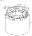
- FIG. 2 is a perspective view of a U-phase coil molding including the coils and the bus bars integrated in the motor according to the exemplary embodiment.
- Coils U 11 to U 41 and bus bars 51 , 54 are integrated to configure coil molding 61 .
- the following description may refer to a first end, provided with bus bar 51 , of coil molding 61 as an “upper” end and a second opposite end as a “lower” end in the Z-axis direction.
- Bus bar 51 in coil molding 61 is a tabular member having a substantially semiannular shape when viewed in the Z-axis direction.
- Bus bar 51 has ends respectively integrated with lead parts U 11 a , U 32 a of coils U 11 , U 32 .
- Bus bar 51 has lead part 51 b electrically connected to a power source (in the U-phase; not depicted).
- Bus bar 54 is a tabular member having a substantially annular shape when viewed in the Z-axis direction.
- Bus bar 54 has the plurality of lead parts 54 a .
- Coils U 22 , U 41 respectively have lead parts U 22 a , U 41 a integrated with lead parts 54 a , 54 a of bus bar 54 .
- Bus bar 54 has potential corresponding to neutral point potential of motor 1 .
- a set of coils U 11 , U 22 are directly integrated with each other without bus bars 51 , 54 being interposed.
- Another set of coils U 32 , U 41 are directly integrated with each other similarly to coils U 11 , U 22 .
- coil U 11 and coil U 22 having opposite winding directions generate magnetic flux opposite to each other.
- Coil U 32 and coil U 41 similarly generate magnetic flux opposite to each other.
- Coils U 11 to U 41 and bus bars 51 , 54 are each made of a copper material. Coils U 11 to U 41 are each made of copper wire having a rectangular section.
- FIG. 3 is a perspective view of V-phase coil molding 62 in the motor according to the exemplary embodiment.
- FIG. 4 is a perspective view of W-phase coil molding 63 in the motor according to the exemplary embodiment.
- bus bar 52 is a tabular member having a substantially semiannular shape when viewed in the Z-axis direction.
- Bus bar 52 has ends respectively integrated with lead parts V 12 a , V 31 a of coils V 12 , V 31 .
- Bus bar 52 has lead part 52 b electrically connected to a power source (in the V-phase; not depicted).
- the set of adjacent coils V 12 , V 21 are directly integrated with each other similarly to coils U 11 , U 22 and the like.
- the other set of adjacent coils V 31 , V 42 are directly integrated with each other.
- Coils V 12 to V 42 and bus bar 52 are each made of a copper material. Coils V 12 to V 42 are each made of copper wire having a rectangular section.
- bus bar 53 is a tabular member having a substantially semiannular shape when viewed in the Z-axis direction.
- Bus bar 53 has ends respectively integrated with lead parts W 11 a , W 32 a of coils W 11 , W 32 .
- Bus bar 53 has lead part 53 b electrically connected to a power source (in the W-phase; not depicted).
- a set of adjacent coils W 11 , W 22 are integrated with each other similarly to coils U 11 , U 22 and the like.
- Another set of adjacent coils W 32 , W 41 are similarly integrated with each other.
- Coils W 11 to W 41 and bus bar 53 are each made of a copper material. Coils W 11 to W 41 are each made of copper wire having a rectangular section.
- FIG. 5 is a perspective view of U, V, and W-phase coil molding 64 combined in the motor according to the exemplary embodiment.
- coil molding 64 having the respective phases can be integrated with bus bars 51 to 54 .
- this may lead to complication in shape and difficulty in formation of the coil molding. For example, it may be difficult to remove a copper material from a casting mold, as to be described later. This may also lead to decrease in assembly aligning margin during assembling coil moldings 61 to 63 to stator 4 .
- U-phase coils include coils U 11 to U 41 integrated with bus bars 51 , 54 to configure coil molding 61
- V-phase coils include two types of coils, namely, the set of adjacent coils V 12 , V 21 integrated to configure coil molding 62 a (see FIG. 3 and FIG. 7C ) and the other set of adjacent coils V 31 , V 42 integrated to configure coil molding 62 b (see FIG. 3 and FIG. 7C )
- W-phase coils include two types of integrated coils similarly to the V-phase coils.
- Coils V 12 to V 42 and bus bars 52 , 54 , as well as coils W 11 to W 41 and bus bars 53 , 54 , are electrically connected through joining by fusing, for example.
- Coil molding 64 depicted in FIG. 5 includes aligned coil moldings 61 to 63 in the respective phases (see FIG. 7D ).
- Coil groups and the bus bars form integral structures having variations not limited to the above, but can be obviously modified appropriately in accordance with specifications of motor 1 , capacity of assembly equipment for stator 4 or the coils, and the like.
- V-phase coil moldings 62 a , 62 b and W-phase coil moldings 63 a , 63 b can be formed in manners similarly to the following manner.
- the following casting mold needs to have a cavity having a shape corresponding to all the coils and all the bus bars incorporated together.
- FIG. 6A , FIG. 6B , and FIG. 6C are explanatory views on a method of manufacturing coil molding 61 in the motor according to the exemplary embodiment.
- Coils U 11 to U 41 and bus bars 51 , 54 are integrally molded by casting copper.
- casting mold 70 has inner cavity 71 shaped correspondingly to integrated coils U 11 to U 41 , bus bars 51 , 54 , and lead parts of coils U 11 to U 41 and bus bars 51 , 54 .
- Molten copper is pressurized and poured into cavity 71 , and the copper is cooled to be solidified to obtain coil molding 61 as depicted in FIG. 6B .
- Coil molding 61 is subsequently removed from casting mold 70 , and insulating treatment is applied to an entire surface of coil molding 61 to provide insulating coating 80 as depicted in FIG. 6C .
- the insulating treatment is executed to electrically insulate coil molding 61 from stator 4 .
- the insulating treatment may be executed through electrodeposition coating or the like, but the present disclosure is not particularly limited to this case.
- a metallic material for casting may not be copper, and may be selected from aluminum, zinc, magnesium, iron, steel use stainless (SUS), brass, and the like.
- the method of manufacturing a molded product is not limited to casting, but can adopt any other technique.
- the molded product can be carved out of a solid material selected from copper, aluminum, zinc, magnesium, iron, SUS, brass, and the like.
- separately molded components may be joined together through cold pressure welding, welding, or the like.
- FIG. 7A to FIG. 7F are explanatory views on the method of assembling stator 4 in the motor according to the exemplary embodiment.
- coil molding 61 and four teeth 42 FIG. 7A ).
- Teeth 42 are respectively attached to four coils U 11 to U 41 in coil molding 61 ( FIG. 7B ).
- V-phase coil moldings 62 a , 62 b and W-phase coil moldings 63 a , 63 b , and teeth 42 are respectively attached to coils V 12 to W 41 ( FIG. 7C ).
- Coil moldings 61 to 63 b provided with teeth 42 are subsequently aligned at predetermined positions to be combined and form an annular shape.
- Stator core 41 is prepared ( FIG. 7D ).
- Coil molding 64 including aligned coil moldings 61 to 63 b is attached to stator core 41 ( FIG. 7E ).
- the both ends of bus bar 52 and lead parts 54 a , 54 a of bus bar 54 are respectively joined to four lead parts of V-phase coil moldings 62 a , 62 b .
- the both ends of bus bar 53 and lead parts 54 a , 54 a of bus bar 54 are respectively joined to four lead parts of W-phase coil moldings 63 a , 63 b to complete assembly of stator 4 ( FIG. 7F ).
- Bus bars 52 to 54 and coil moldings 62 a to 63 b in the V and W phases may be joined subsequently to the process depicted in FIG. 7D .
- the present exemplary embodiment provides coil molding 61 including coils U 11 to U 41 and bus bars 51 , 54 molded integrally.
- the present exemplary embodiment thus achieves elimination of a process of winding the coils and a process of connecting the coils and the bus bars.
- Motor 1 including the coil molding thus obtained achieves reduction in manufacturing cost for motor 1 .
- coil U 11 and coil U 22 corresponding the U-phase and the U-bar phase, respectively, are directly integrated with each other.
- This configuration eliminates connecting wire between these phases.
- This configuration also eliminates a connection process between connecting wire and the coils.
- Coil U 32 , coil U 41 , coils V 21 to V 42 , and coils W 11 to W 41 similarly need neither connecting wire nor a process of connecting the connecting wire.
- insulating treatment can be applied to the surfaces of coil moldings 61 to 63 b at one time, achieving simplification of the process.
- At least either the coil and the bus bar or a plurality of coils are molded integrally. This facilitates handling coil moldings 61 to 63 b provided with teeth 42 , and achieves reduction in assembling cost for stator 4 .
- Coils U 11 to U 41 , V 12 to V 42 , and W 11 to W 41 are each made of copper wire having a rectangular section, and can thus be disposed in slots 43 without any gaps. This leads to improvement in space factor of the coils. This configuration accordingly enables reduction in size of motor 1 and improvement in torque density.
- the present exemplary embodiment provides coil molding 61 that is attached to stator 4 of motor 1 and includes coils U 11 to U 41 wound respectively around the plurality of teeth 42 of stator 4 and bus bars 51 , 54 connected to coils U 11 to U 41 and molded integrally with coils U 11 to U 41 , bus bars 51 , 54 each having a substantially semiannular shape when viewed from the central axis of motor 1 .
- This configuration achieves elimination of a process of winding the coils and a process of connecting the coils and the bus bars for reduction in manufacturing cost for motor 1 .
- the present exemplary embodiment provides coil molding 61 including the set of coils U 11 , U 22 wound respectively around the plurality of teeth 42 , the set of coils U 11 , U 22 being molded integrally with each other.
- This configuration achieves elimination of a process of winding the coils and a process of connecting the coils for reduction in manufacturing cost for motor 1 .
- Integrally molded coils U 11 , U 22 are each preferred to have a natural number of turns.
- the set of integrally molded coils U 11 , U 22 may include first coil U 11 having a clockwise winding direction when viewed from the center of the motor, and second coil U 22 having a counterclockwise winding direction when viewed from the center of the motor.
- the set of coils U 11 , U 22 and at least one of bus bars 51 , 54 are preferred to be molded integrally.
- the set of integrally molded coils U 11 , U 22 may be disposed adjacent to each other.
- the present exemplary embodiment provides motor 1 including the cover case accommodating shaft 2 , rotor 3 provided in contact with the outer circumference of shaft 2 , and stator 4 disposed outside rotor 3 and constantly spaced apart from rotor 3 .
- Stator 4 includes stator core 41 having a substantially annular shape, the plurality of teeth 42 provided at equal intervals along the inner circumference of stator core 41 , slots 43 each provided between adjacent teeth 42 , and coil molding 61 attached to teeth 42 and disposed in slots 43 .
- This configuration achieves motor 1 including coil molding 61 manufactured without a process of winding coils or a process of connecting the coil and a bus bar or connecting the coils, for reduction in manufacturing cost for motor 1 .
- the present exemplary embodiment further provides a method of manufacturing coil molding 61 , the method including: preparing casting mold 70 having inner cavity 71 shaped correspondingly to integration between at least one of coils U 11 to U 41 and at least one of bus bars 51 , 54 ; pouring, into cavity 71 , a single molten metallic material selected from copper, aluminum, zinc, magnesium, iron, steel use stainless (SUS), and brass; cooling casting mold 70 to solidify the metallic material in cavity 71 ; removing the solidified metallic material from casting mold 70 to obtain coil molding 61 ; and applying insulating treatment to an entire surface of coil molding 61 .
- This configuration achieves elimination of a process of winding the coils and a process of connecting the coils and the bus bars for reduction in manufacturing cost for motor 1 .
- the present exemplary embodiment also provides a method of manufacturing coil molding 61 , the method including: preparing casting mold 70 having inner cavity 71 shaped correspondingly to integration of at least one set of adjacent coils U 11 , U 22 ; pouring, into cavity 71 , a single molten metallic material selected from copper, aluminum, zinc, magnesium, iron, steel use stainless (SUS), and brass; cooling casting mold 70 to solidify the metallic material in cavity 71 ; removing the solidified metallic material from casting mold 70 to obtain coil molding 61 ; and applying insulating treatment to an entire surface of coil molding 61 .
- This configuration achieves elimination of a process of winding the coils and a process of connecting the coils for reduction in manufacturing cost for motor 1 .
- the present exemplary embodiment further provides a method of assembling a stator, the method including: preparing coil molding 61 ; attaching teeth 42 of stator 4 to coils U 11 to U 41 of coil molding 61 ; attaching coil molding 61 provided with teeth 42 to stator core 41 ; and joining coil molding 61 and bus bar 53 not integrated with coil molding 61 .
- bus bars 51 , 54 each have a plane being parallel to the central axis and having a sectional shape
- coils U 11 to U 41 facing each other with teeth 42 being interposed each have a section being vertical to the central axis and having a shape that may be different from the sectional shape of bus bars 51 , 54 .
- At least one of coils Ulf to U 41 and at least one of bus bars 51 , 54 may be integrated with each other by material joining.
- FIG. 8 is an enlarged view of part of the coil molding depicted in FIG. 2 .
- coils U 11 to U 41 , V 12 to V 42 , and W 11 to W 41 each have a natural number of winding times (hereinafter, called a number of turns).
- coil U 11 includes winding wire having three turns and then extending from above toward coil U 22 to be integrated with coil U 22 .
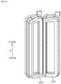
- FIG. 9 is a perspective view of a coil molding according to a modification example.
- the winding wire of coil U 11 may alternatively have two turns and then extend from below to be integrated. That is, each coil may have 2.5 turns.
- Such a configuration slightly decreases the number of turns of the coil for each one of the teeth.
- This configuration reduces the numbers of turns for two coils, in other words, wire length of the coils. This leads to material cost reduction.
- This configuration also decreases winding density above the coils. This leads to increase in space margin above the coils. This configuration facilitates joining by fusing or the like.
- the above exemplary embodiment exemplifies the structure including adjacent coils directly integrated with each other.
- This structure achieves decrease in contact point with the bus bar and increase in space above the coils.
- This structure is effectively applied for reduction in the number or disposition density of the lead parts.
- the present disclosure is not particularly limited to this case.
- the above exemplary embodiment exemplifies integration of the coil having the clockwise winding direction and the coil having the counterclockwise winding direction.
- coils each having the clockwise winding direction or coils each having the counterclockwise winding direction may be integrated with each other. Disposition of these coils may be modified appropriately in accordance with the number of poles, the number of slots, or the like of motor 1 .
- the coil having the clockwise winding direction and the coil having the counterclockwise winding direction may be disposed to be spaced apart from each other with a bus bar being interposed.
- the exemplary embodiment as well as the modification example exemplify the coil molding including the plurality of coils molded integrally with the plurality of bus bars.
- a plurality of coils and a single bus bar for example, coils U 11 to U 41 and bus bar 51 , may be molded integrally.
- a single coil such as coil U 11 and bus bar 51 may be molded integrally with each other.
- the above exemplary embodiment provides three as the number of turns of each of coils U 11 to U 41 , V 12 to V 42 , and W 11 to W 41 .
- the present disclosure is not particularly limited to this case.
- the number of turns may be changed appropriately in accordance with performance specification of motor 1 or the like.
- coils U 11 , U 22 molded integrally in coil molding 61 may each have a number of turns calculated by multiplying a natural number by a number obtained through adding an integer more than or equal to one and 1 ⁇ 2.
- the present disclosure provides a coil molding having an improved space factor of a coil in a stator.
- the coil molding also achieves elimination of a process of winding the coil and a process of connecting the coil and a bus bar.
- the present disclosure is thus useful for achievement of high efficiency and low cost for a motor.
Abstract
Description
- PTL 1: Unexamined German Patent Publication No. 102012212637
-
- 1: motor
- 2: shaft
- 3: rotor
- 4: stator
- 31: magnet
- 41: stator core
- 42: teeth
- 43: slot
- 51, 52, 53, 54: bus bar
- 61, 62, 62 a, 62 b, 63, 63 a, 63 b, 64: coil molding
- 70: casting mold
- 71: cavity
- 80: insulating coating
- U11, U22, U32, U41, V12, V21, V31, V42, W11, W22, W32, W41: coil
- U11 a, U22 a, U32 a, U41 a, V12 a, V31 a, W11 a, W32 a, 51 b, 52 b, 53 b, 54 a: lead part
Claims (12)
Applications Claiming Priority (4)
| Application Number | Priority Date | Filing Date | Title |
|---|---|---|---|
| JP2017-006957 | 2017-01-18 | ||
| JP2017006957 | 2017-01-18 | ||
| JPJP2017-006957 | 2017-01-18 | ||
| PCT/JP2017/039707 WO2018135086A1 (en) | 2017-01-18 | 2017-11-02 | Molded coil body, method for producing same, motor, and method for assembling stator |
Publications (2)
| Publication Number | Publication Date |
|---|---|
| US20200212770A1 US20200212770A1 (en) | 2020-07-02 |
| US11223260B2 true US11223260B2 (en) | 2022-01-11 |
Family
ID=62908113
Family Applications (1)
| Application Number | Title | Priority Date | Filing Date |
|---|---|---|---|
| US16/475,727 Active US11223260B2 (en) | 2017-01-18 | 2017-11-02 | Molded coil body with coil and semiannular busbars integrally connected with coils in the molded coil body |
Country Status (5)
| Country | Link |
|---|---|
| US (1) | US11223260B2 (en) |
| EP (1) | EP3573215A4 (en) |
| JP (1) | JP7016001B2 (en) |
| CN (1) | CN110199458B (en) |
| WO (1) | WO2018135086A1 (en) |
Families Citing this family (11)
| Publication number | Priority date | Publication date | Assignee | Title |
|---|---|---|---|---|
| DE102018215986A1 (en) | 2018-09-19 | 2020-03-19 | Fraunhofer-Gesellschaft zur Förderung der angewandten Forschung e.V. | Production of a helix, permanent shape for a helix and helix |
| DE102018215972A1 (en) * | 2018-09-19 | 2020-03-19 | Fraunhofer-Gesellschaft zur Förderung der angewandten Forschung e.V. | Method and tool for producing a coil and coil produced therewith |
| WO2020071532A1 (en) * | 2018-10-04 | 2020-04-09 | 三菱電機株式会社 | Method for manufacturing coil component, method for manufacturing electric machine, coil component, and electric machine |
| JP7373827B2 (en) * | 2019-02-19 | 2023-11-06 | 株式会社アスター | Coil zygote and method for manufacturing the coil zygote |
| JP7376902B2 (en) * | 2019-02-19 | 2023-11-09 | 株式会社アスター | Coil zygote and method for manufacturing the coil zygote |
| WO2020246406A1 (en) * | 2019-06-06 | 2020-12-10 | 日本電産株式会社 | Stator, motor, and method of manufacturing stator |
| DE102019212850A1 (en) * | 2019-08-27 | 2021-03-04 | Volkswagen Aktiengesellschaft | Casting tool for cast electrotechnical coils |
| DE102019213232A1 (en) * | 2019-09-02 | 2021-03-04 | Fraunhofer-Gesellschaft zur Förderung der angewandten Forschung e.V. | GROUP OF ROTATING ELECTRIC MACHINERY AND METHOD OF MANUFACTURING ROTATING ELECTRIC MACHINERY |
| CN111756144A (en) * | 2020-07-03 | 2020-10-09 | 苏州达思灵电机有限公司 | Laminated gap-bridge-connected flat-wire doubly salient excitation motor stator |
| KR20220028784A (en) * | 2020-08-31 | 2022-03-08 | 현대모비스 주식회사 | Coil assembly and motor having the same |
| KR20230012816A (en) | 2021-07-16 | 2023-01-26 | 현대자동차주식회사 | Casting coil for motor assembly, manufacturing method thereof and the motor assembly |
Citations (25)
| Publication number | Priority date | Publication date | Assignee | Title |
|---|---|---|---|---|
| EP1035630A2 (en) | 1999-03-09 | 2000-09-13 | Toyota Jidosha Kabushiki Kaisha | Rotating electric machine and method for connecting coils of rotating electric machine |
| JP2004336969A (en) | 2003-05-12 | 2004-11-25 | Fuji Heavy Ind Ltd | Casting device |
| US20050236921A1 (en) * | 2004-04-26 | 2005-10-27 | Denso Corporation | Concentrated winding stator coil for an electric rotary machine |
| US20050236922A1 (en) * | 2004-04-26 | 2005-10-27 | Denso Corporation | Concentrated winding stator coil for an electric rotary machine |
| US20050248228A1 (en) * | 2004-04-21 | 2005-11-10 | Denso Corporation | Concentrated winding stator coil for an electric rotary machine |
| US20060138883A1 (en) | 2004-12-28 | 2006-06-29 | Hitachi, Ltd. | Motor for electric power steering and method for manufacturing the same |
| EP1729398A2 (en) | 2005-05-30 | 2006-12-06 | Hitachi, Ltd. | Production method for rotating electric machine and stator coils, and electric power steering motor |
| JP2007267463A (en) | 2006-03-28 | 2007-10-11 | Hitachi Ltd | Rotating electric machine and manufacturing method for rotary electric machine |
| US20080201935A1 (en) | 2007-02-26 | 2008-08-28 | Hitachi, Ltd. | Manufacturing Method for Rotary Electric Machine and Stator |
| JP2010016970A (en) | 2008-07-03 | 2010-01-21 | Toyota Motor Corp | Concentrated winding stator and manufacturing method thereof |
| US20100052461A1 (en) * | 2006-11-30 | 2010-03-04 | Kei Sasaki | Insulating member and stator |
| JP2010110122A (en) | 2008-10-30 | 2010-05-13 | Toyota Motor Corp | Rotating electrical machine |
| US20110068647A1 (en) * | 2008-05-16 | 2011-03-24 | Mitsubishi Electric Corporation | Rotary electric machine |
| EP2387135A2 (en) | 2010-05-10 | 2011-11-16 | Fraunhofer-Gesellschaft zur Förderung der angewandten Forschung | Electrotechnical cast coil, method for producing such a coil and electric machines using such coils |
| US20110297474A1 (en) * | 2009-02-23 | 2011-12-08 | Nidec Corporation | Stator, bus bar unit, motor, and power steering device |
| CN102577035A (en) | 2010-10-14 | 2012-07-11 | 丰田自动车株式会社 | Motor |
| JP2014007829A (en) | 2012-06-22 | 2014-01-16 | Aisin Aw Co Ltd | Stator and manufacturing method therefor |
| DE102012212637A1 (en) | 2012-07-18 | 2014-01-23 | Fraunhofer-Gesellschaft zur Förderung der angewandten Forschung e.V. | Casting electrical coil |
| WO2014111179A2 (en) | 2013-01-18 | 2014-07-24 | Volkswagen Aktiengesellschaft | Electrotechnical coil and/or coil winding, method for the production thereof and electrical appliance |
| DE102013205240A1 (en) | 2013-03-25 | 2014-09-25 | Robert Bosch Gmbh | Rotor or stator for an electric machine and method for its manufacture |
| JP2014207860A (en) | 2014-06-03 | 2014-10-30 | 日本電産株式会社 | Motor, and power steering device |
| JP2015002614A (en) | 2013-06-14 | 2015-01-05 | アイシン・エィ・ダブリュ株式会社 | Coil casting device and coil casting method |
| EP2833520A1 (en) | 2012-07-03 | 2015-02-04 | Aisin Aw Co., Ltd. | Stator |
| JP2016028550A (en) | 2014-07-01 | 2016-02-25 | ダイキン工業株式会社 | Armature |
| JP2017158384A (en) | 2016-03-04 | 2017-09-07 | 住友重機械工業株式会社 | Stator, motor, and method of manufacturing stator |
Family Cites Families (3)
| Publication number | Priority date | Publication date | Assignee | Title |
|---|---|---|---|---|
| JP4789676B2 (en) * | 2006-03-29 | 2011-10-12 | トヨタ自動車株式会社 | Terminal module for rotating electric machine and rotating electric machine |
| US7723879B2 (en) * | 2006-12-12 | 2010-05-25 | Nidec Corporation | Motor having multiple busbar plates and wire for the same |
| JP5691968B2 (en) * | 2011-09-26 | 2015-04-01 | トヨタ自動車株式会社 | Rotating electric machine stator |
-
2017
- 2017-11-02 US US16/475,727 patent/US11223260B2/en active Active
- 2017-11-02 JP JP2018562886A patent/JP7016001B2/en active Active
- 2017-11-02 WO PCT/JP2017/039707 patent/WO2018135086A1/en unknown
- 2017-11-02 CN CN201780083417.0A patent/CN110199458B/en active Active
- 2017-11-02 EP EP17893300.8A patent/EP3573215A4/en active Pending
Patent Citations (34)
| Publication number | Priority date | Publication date | Assignee | Title |
|---|---|---|---|---|
| EP1035630A2 (en) | 1999-03-09 | 2000-09-13 | Toyota Jidosha Kabushiki Kaisha | Rotating electric machine and method for connecting coils of rotating electric machine |
| JP2000324739A (en) | 1999-03-09 | 2000-11-24 | Toyota Motor Corp | Electric rotating machine and connection method of coils of electric rotating machine |
| JP2004336969A (en) | 2003-05-12 | 2004-11-25 | Fuji Heavy Ind Ltd | Casting device |
| US20050248228A1 (en) * | 2004-04-21 | 2005-11-10 | Denso Corporation | Concentrated winding stator coil for an electric rotary machine |
| US20050236921A1 (en) * | 2004-04-26 | 2005-10-27 | Denso Corporation | Concentrated winding stator coil for an electric rotary machine |
| US20050236922A1 (en) * | 2004-04-26 | 2005-10-27 | Denso Corporation | Concentrated winding stator coil for an electric rotary machine |
| US20060138883A1 (en) | 2004-12-28 | 2006-06-29 | Hitachi, Ltd. | Motor for electric power steering and method for manufacturing the same |
| JP2006187175A (en) | 2004-12-28 | 2006-07-13 | Hitachi Ltd | Electric power steering motor and manufacturing method therefor |
| EP1729398A2 (en) | 2005-05-30 | 2006-12-06 | Hitachi, Ltd. | Production method for rotating electric machine and stator coils, and electric power steering motor |
| JP2007267463A (en) | 2006-03-28 | 2007-10-11 | Hitachi Ltd | Rotating electric machine and manufacturing method for rotary electric machine |
| US7855484B2 (en) * | 2006-11-30 | 2010-12-21 | Toyota Jidosha Kabushiki Kaisha | Insulating member and stator |
| US20100052461A1 (en) * | 2006-11-30 | 2010-03-04 | Kei Sasaki | Insulating member and stator |
| US20080201935A1 (en) | 2007-02-26 | 2008-08-28 | Hitachi, Ltd. | Manufacturing Method for Rotary Electric Machine and Stator |
| JP2008211880A (en) | 2007-02-26 | 2008-09-11 | Hitachi Ltd | Manufacturing method for rotating electrical machines and stators |
| US20110068647A1 (en) * | 2008-05-16 | 2011-03-24 | Mitsubishi Electric Corporation | Rotary electric machine |
| JP2010016970A (en) | 2008-07-03 | 2010-01-21 | Toyota Motor Corp | Concentrated winding stator and manufacturing method thereof |
| JP2010110122A (en) | 2008-10-30 | 2010-05-13 | Toyota Motor Corp | Rotating electrical machine |
| US20110297474A1 (en) * | 2009-02-23 | 2011-12-08 | Nidec Corporation | Stator, bus bar unit, motor, and power steering device |
| EP2387135A2 (en) | 2010-05-10 | 2011-11-16 | Fraunhofer-Gesellschaft zur Förderung der angewandten Forschung | Electrotechnical cast coil, method for producing such a coil and electric machines using such coils |
| CN102577035A (en) | 2010-10-14 | 2012-07-11 | 丰田自动车株式会社 | Motor |
| US20120217836A1 (en) | 2010-10-14 | 2012-08-30 | Toyota Jidosha Kabushiki Kaisha | Motor |
| EP2827476A1 (en) | 2012-06-22 | 2015-01-21 | Aisin Aw Co., Ltd. | Stator and method for manufacturing stator |
| JP2014007829A (en) | 2012-06-22 | 2014-01-16 | Aisin Aw Co Ltd | Stator and manufacturing method therefor |
| US20150155750A1 (en) | 2012-06-22 | 2015-06-04 | Aisin Aw Co., Ltd. | Stator and manufacturing method of stator |
| EP2833520A1 (en) | 2012-07-03 | 2015-02-04 | Aisin Aw Co., Ltd. | Stator |
| US20150162793A1 (en) | 2012-07-03 | 2015-06-11 | Aisin Aw Co., Ltd. | Stator |
| DE102012212637A1 (en) | 2012-07-18 | 2014-01-23 | Fraunhofer-Gesellschaft zur Förderung der angewandten Forschung e.V. | Casting electrical coil |
| WO2014111179A2 (en) | 2013-01-18 | 2014-07-24 | Volkswagen Aktiengesellschaft | Electrotechnical coil and/or coil winding, method for the production thereof and electrical appliance |
| DE102013205240A1 (en) | 2013-03-25 | 2014-09-25 | Robert Bosch Gmbh | Rotor or stator for an electric machine and method for its manufacture |
| JP2015002614A (en) | 2013-06-14 | 2015-01-05 | アイシン・エィ・ダブリュ株式会社 | Coil casting device and coil casting method |
| JP2014207860A (en) | 2014-06-03 | 2014-10-30 | 日本電産株式会社 | Motor, and power steering device |
| JP2016028550A (en) | 2014-07-01 | 2016-02-25 | ダイキン工業株式会社 | Armature |
| US20170155296A1 (en) | 2014-07-01 | 2017-06-01 | Daikin Industries, Ltd. | Armature, rotating electric machine, cross-flow fan, and method for manufacturing pair of teeth of armature |
| JP2017158384A (en) | 2016-03-04 | 2017-09-07 | 住友重機械工業株式会社 | Stator, motor, and method of manufacturing stator |
Non-Patent Citations (7)
| Title |
|---|
| Communication pursuant to Article 94(3) EPC dated Nov. 19, 2020 for the related European Patent Application No. 17893300.8. |
| Communication pursuant to Article 94(3) EPC dated Sep. 14, 2021 for the related European Patent Application No. 17893300.8. |
| English Translation of Chinese Search Report dated Dec. 11, 2020 for the related Chinese Patent Application No. 201780083417.0. |
| Groninger Met al : "Casting production of coils for electrical machines", Electric Drives Production Conference (EDPC), 2011 1st International, IEEE, Sep. 28, 2011 (Sep. 28, 2011), pp. 159-161, XP032000385. |
| International Search Report of PCT application No. PCT/JP2017/039707 dated Jan. 16, 2018. |
| M. GRONINGER ; F. HORCH ; A. KOCK ; H. PLETEIT ; B. PONICK ; D. SCHMIDT ; F.-J. WOSTMANN: "Casting production of coils for electrical machines", ELECTRIC DRIVES PRODUCTION CONFERENCE (EDPC), 2011 1ST INTERNATIONAL, IEEE, 28 September 2011 (2011-09-28), pages 159 - 161, XP032000385, ISBN: 978-1-4577-1371-2, DOI: 10.1109/EDPC.2011.6085534 |
| The Extended European Search Report dated Sep. 18, 2019 for the related European Patent Application No. 17893300.8. |
Also Published As
| Publication number | Publication date |
|---|---|
| JPWO2018135086A1 (en) | 2019-11-07 |
| EP3573215A1 (en) | 2019-11-27 |
| EP3573215A4 (en) | 2019-11-27 |
| JP7016001B2 (en) | 2022-02-21 |
| CN110199458A (en) | 2019-09-03 |
| US20200212770A1 (en) | 2020-07-02 |
| WO2018135086A1 (en) | 2018-07-26 |
| CN110199458B (en) | 2021-09-07 |
Similar Documents
| Publication | Publication Date | Title |
|---|---|---|
| US11223260B2 (en) | Molded coil body with coil and semiannular busbars integrally connected with coils in the molded coil body | |
| JP5944066B2 (en) | PERMANENT MAGNET MOTOR, DRIVE DEVICE INTEGRATED PERMANENT MAGNET MOTOR AND MANUFACTURING METHOD FOR PERMANENT MAGNET MOTOR | |
| JP4783012B2 (en) | Electric power steering motor and manufacturing method thereof | |
| US10615671B2 (en) | Stator and method for manufacturing stator | |
| JP5480106B2 (en) | Rotating electric machine | |
| US11190073B2 (en) | Motor having increased passage for refrigerant for cooling coils | |
| JP2007202263A (en) | Electric power steering motor | |
| JP2018068090A (en) | Synchronous reluctance type rotary electric machine | |
| US10965198B2 (en) | Coil and motor using same | |
| CN107615630A (en) | Armature core, armature and linear motor | |
| JP5998871B2 (en) | Rotating electric machine stator | |
| US10992198B2 (en) | Motor | |
| EP3573218B1 (en) | Connection structure for coil and bus bar, and motor having same | |
| JP5183894B2 (en) | Iron core around which winding is wound, rotating electric machine, and linear motor | |
| US20210344242A1 (en) | Coil device | |
| CN112868164A (en) | Coil mounting structure | |
| JP2014082935A (en) | Stator of rotary electric machine, and rotary electric machine having the same | |
| WO2021241113A1 (en) | Coil, stator comprising same, and motor | |
| EP4300774A1 (en) | Rotating electrical machine | |
| JP2010288398A (en) | Stator of motor | |
| JP6735782B2 (en) | Motor bus ring structure | |
| JP2020065441A (en) | Motor bus ring structure | |
| JP2015231261A (en) | Three-phase induction motor |
Legal Events
| Date | Code | Title | Description |
|---|---|---|---|
| FEPP | Fee payment procedure |
Free format text: ENTITY STATUS SET TO UNDISCOUNTED (ORIGINAL EVENT CODE: BIG.); ENTITY STATUS OF PATENT OWNER: LARGE ENTITY |
|
| AS | Assignment |
Owner name: PANASONIC INTELLECTUAL PROPERTY MANAGEMENT CO., LTD., JAPAN Free format text: ASSIGNMENT OF ASSIGNORS INTEREST;ASSIGNORS:YOSHIKAWA, YUICHI;NUKADA, KEIICHIRO;YAMAUCHI, HIROKAZU;AND OTHERS;SIGNING DATES FROM 20190508 TO 20190509;REEL/FRAME:051154/0895 |
|
| STPP | Information on status: patent application and granting procedure in general |
Free format text: NON FINAL ACTION MAILED |
|
| STPP | Information on status: patent application and granting procedure in general |
Free format text: RESPONSE TO NON-FINAL OFFICE ACTION ENTERED AND FORWARDED TO EXAMINER |
|
| STPP | Information on status: patent application and granting procedure in general |
Free format text: FINAL REJECTION MAILED |
|
| STPP | Information on status: patent application and granting procedure in general |
Free format text: RESPONSE AFTER FINAL ACTION FORWARDED TO EXAMINER |
|
| STPP | Information on status: patent application and granting procedure in general |
Free format text: ADVISORY ACTION MAILED |
|
| STPP | Information on status: patent application and granting procedure in general |
Free format text: DOCKETED NEW CASE - READY FOR EXAMINATION |
|
| STPP | Information on status: patent application and granting procedure in general |
Free format text: NOTICE OF ALLOWANCE MAILED -- APPLICATION RECEIVED IN OFFICE OF PUBLICATIONS |
|
| STPP | Information on status: patent application and granting procedure in general |
Free format text: PUBLICATIONS -- ISSUE FEE PAYMENT RECEIVED |
|
| STPP | Information on status: patent application and granting procedure in general |
Free format text: PUBLICATIONS -- ISSUE FEE PAYMENT VERIFIED |
|
| STCF | Information on status: patent grant |
Free format text: PATENTED CASE |