US11220078B2 - Ball hitch tip out plug, triangle leg tip out plug, combination, and tip out plug tool - Google Patents
Ball hitch tip out plug, triangle leg tip out plug, combination, and tip out plug tool Download PDFInfo
- Publication number
- US11220078B2 US11220078B2 US16/608,659 US201816608659A US11220078B2 US 11220078 B2 US11220078 B2 US 11220078B2 US 201816608659 A US201816608659 A US 201816608659A US 11220078 B2 US11220078 B2 US 11220078B2
- Authority
- US
- United States
- Prior art keywords
- plug
- receiver
- cavity
- dimensioned
- tire mold
- Prior art date
- Legal status (The legal status is an assumption and is not a legal conclusion. Google has not performed a legal analysis and makes no representation as to the accuracy of the status listed.)
- Expired - Fee Related
Links
Images


Classifications
-
- B—PERFORMING OPERATIONS; TRANSPORTING
- B29—WORKING OF PLASTICS; WORKING OF SUBSTANCES IN A PLASTIC STATE IN GENERAL
- B29D—PRODUCING PARTICULAR ARTICLES FROM PLASTICS OR FROM SUBSTANCES IN A PLASTIC STATE
- B29D30/00—Producing pneumatic or solid tyres or parts thereof
- B29D30/06—Pneumatic tyres or parts thereof (e.g. produced by casting, moulding, compression moulding, injection moulding, centrifugal casting)
- B29D30/72—Side-walls
-
- B—PERFORMING OPERATIONS; TRANSPORTING
- B29—WORKING OF PLASTICS; WORKING OF SUBSTANCES IN A PLASTIC STATE IN GENERAL
- B29D—PRODUCING PARTICULAR ARTICLES FROM PLASTICS OR FROM SUBSTANCES IN A PLASTIC STATE
- B29D30/00—Producing pneumatic or solid tyres or parts thereof
- B29D30/06—Pneumatic tyres or parts thereof (e.g. produced by casting, moulding, compression moulding, injection moulding, centrifugal casting)
- B29D30/0601—Vulcanising tyres; Vulcanising presses for tyres
- B29D30/0606—Vulcanising moulds not integral with vulcanising presses
-
- B—PERFORMING OPERATIONS; TRANSPORTING
- B29—WORKING OF PLASTICS; WORKING OF SUBSTANCES IN A PLASTIC STATE IN GENERAL
- B29C—SHAPING OR JOINING OF PLASTICS; SHAPING OF MATERIAL IN A PLASTIC STATE, NOT OTHERWISE PROVIDED FOR; AFTER-TREATMENT OF THE SHAPED PRODUCTS, e.g. REPAIRING
- B29C33/00—Moulds or cores; Details thereof or accessories therefor
- B29C33/42—Moulds or cores; Details thereof or accessories therefor characterised by the shape of the moulding surface, e.g. ribs or grooves
- B29C33/424—Moulding surfaces provided with means for marking or patterning
- B29C33/428—For altering indicia, e.g. data, numbers
-
- B—PERFORMING OPERATIONS; TRANSPORTING
- B29—WORKING OF PLASTICS; WORKING OF SUBSTANCES IN A PLASTIC STATE IN GENERAL
- B29D—PRODUCING PARTICULAR ARTICLES FROM PLASTICS OR FROM SUBSTANCES IN A PLASTIC STATE
- B29D30/00—Producing pneumatic or solid tyres or parts thereof
- B29D30/06—Pneumatic tyres or parts thereof (e.g. produced by casting, moulding, compression moulding, injection moulding, centrifugal casting)
- B29D30/0601—Vulcanising tyres; Vulcanising presses for tyres
- B29D30/0662—Accessories, details or auxiliary operations
-
- B—PERFORMING OPERATIONS; TRANSPORTING
- B29—WORKING OF PLASTICS; WORKING OF SUBSTANCES IN A PLASTIC STATE IN GENERAL
- B29C—SHAPING OR JOINING OF PLASTICS; SHAPING OF MATERIAL IN A PLASTIC STATE, NOT OTHERWISE PROVIDED FOR; AFTER-TREATMENT OF THE SHAPED PRODUCTS, e.g. REPAIRING
- B29C33/00—Moulds or cores; Details thereof or accessories therefor
- B29C33/30—Mounting, exchanging or centering
- B29C33/306—Exchangeable mould parts, e.g. cassette moulds, mould inserts
-
- B—PERFORMING OPERATIONS; TRANSPORTING
- B29—WORKING OF PLASTICS; WORKING OF SUBSTANCES IN A PLASTIC STATE IN GENERAL
- B29D—PRODUCING PARTICULAR ARTICLES FROM PLASTICS OR FROM SUBSTANCES IN A PLASTIC STATE
- B29D30/00—Producing pneumatic or solid tyres or parts thereof
- B29D30/06—Pneumatic tyres or parts thereof (e.g. produced by casting, moulding, compression moulding, injection moulding, centrifugal casting)
- B29D30/0601—Vulcanising tyres; Vulcanising presses for tyres
- B29D30/0606—Vulcanising moulds not integral with vulcanising presses
- B29D2030/0607—Constructional features of the moulds
-
- B—PERFORMING OPERATIONS; TRANSPORTING
- B29—WORKING OF PLASTICS; WORKING OF SUBSTANCES IN A PLASTIC STATE IN GENERAL
- B29D—PRODUCING PARTICULAR ARTICLES FROM PLASTICS OR FROM SUBSTANCES IN A PLASTIC STATE
- B29D30/00—Producing pneumatic or solid tyres or parts thereof
- B29D30/06—Pneumatic tyres or parts thereof (e.g. produced by casting, moulding, compression moulding, injection moulding, centrifugal casting)
- B29D30/72—Side-walls
- B29D2030/726—Decorating or marking the sidewalls before tyre vulcanization
Definitions
- This invention relates to mold assemblies, and more particularly to mold inserts designed for installation and removal from a mold, such as a tire mold.
- a cured tire requires certain manufacturing information to be molded into a sidewall of the tire.
- federal regulations specify the information that is required to be included on the tire. For example, one part of that required information relates to the curing press in which the tire was vulcanized, and a second part of the required information relates to the week and year that the tire was vulcanized (referred to as the Department of Transportation date code). If the information is provided in incorrect locations on the tire, the sidewall will not conform with the specified format.
- the plug arrangement or plug assembly for a tire mold includes a receiver or jacket having a first face with an irregular shaped cavity extending inwardly therefrom to a first surface.
- a fastener secures the receiver to an associated tire mold.
- a securing member extends from the receiver into the cavity.
- a plug is contoured and dimensioned for mating receipt in the receiver cavity and retained therein by engagement with the securing member.
- the first surface of the receiver includes a first opening extending therethrough dimensioned to receive the fastener.
- the plug includes a recess extending inwardly from a perimeter edge of the plug and the recess is dimensioned to receive the securing member therein.
- the securing member is secured to and extends perpendicularly outward from the first surface of the receiver, and the recess extends in a direction substantially perpendicular to the securing member.
- Another embodiment of the plug has an angled surface provided on a rear face of the plug that faces the first surface of the jacket.
- the angled surface extends inwardly from a first end of the plug, and the plug includes another angled surface extending inwardly from a second end of the plug.
- the securing member preferably includes a spherical portion at a distal end of a stem that is connected to the receiver first surface.
- the spherical portion has a greater cross-sectional dimension than a cross-sectional dimension of the stem.
- the plug includes a recess extending inwardly from a perimeter edge of the plug and dimensioned to receive the stem therein, and the spherical portion of the securing member has a greater cross-sectional dimension than undercut shoulders that define the recess and prevent inadvertent removal of the plug from the jacket/receiver.
- the plug includes first and second angled surfaces that extend inwardly from opposite, first and second ends, respectively, of the plug toward a central planar portion.
- the cavity has a D-shaped perimeter
- the plug has a similarly contoured, D-shaped perimeter.
- a plug assembly for a tire mold includes a jacket/receiver having a first surface with an irregular shaped cavity extending inwardly therefrom, the first surface including a slot.
- a fastener secures the receiver to an associated tire mold.
- a plug is contoured and dimensioned for mating receipt in the receiver cavity, the plug including a protrusion extending from a first surface thereof and dimensioned for receipt in the receiver slot.
- a wall extends above the first surface of the receiver adjacent the slot serving as a fulcrum point for tipping the plug relative to the receiver when received therein.
- the wall preferably extends perpendicular to the slot.
- the protrusion preferably has a triangular shape.
- An outer perimeter of the plug and an inner perimeter of the cavity are dimensioned for a friction fit that retains the plug in the receiver.
- the slot is formed along an edge of the receiver, and the protrusion is formed along an edge of the plug whereby the plug is capable of receipt in the receiver in only a single orientation when the protrusion faces the receiver first surface.
- a combination of plug assemblies for a tire mold includes a first receiver having a first face with an irregular shaped cavity extending inwardly therefrom to a cavity first surface.
- a first fastener secures the first receiver to an associated tire mold.
- a first securing member extends from the receiver into the cavity.
- a first plug is contoured and dimensioned for mating receipt in the first receiver cavity and retained therein by engagement with the first securing member.
- a second receiver has a first surface with an irregular shaped cavity, and the first surface including a slot.
- a second fastener secures the second receiver to the associated tire mold.
- a second plug is contoured and dimensioned for mating receipt in the second receiver cavity, the second plug including a protrusion extending from a first surface thereof and dimensioned for receipt in the second receiver slot.
- At least one of the first plug and the first receiver has a conformation that precludes mating engagement with the second receiver and the second plug, respectively.
- a plug removal tool has an enlarged, first end to facilitate gripping by an associated user, and a second end that includes a pointed tip for engaging the plug mounted to the associated tire mold.
- the pointed tip is preferably urged outwardly from the tool by a biasing member.
- a polymer material surrounds the pointed tip that minimizes potential damage to the associated tire mold when using the plug removal tool.
- One benefit of the present disclosure is the provision of jackets/receivers for tire mold inserts to be designed to prevent the plug from being installed improperly in the tire mold, or to prevent a plug being incorrectly mounted in its associated receiver.
- Another advantage relates to the ease of installing and removing the plugs.
- Yet another benefit is associated with eliminating the potential for damaging the sidewall of the tire mold.
- a still further advantage is the design of plugs that can be installed/removed without the use of a hammer.
- FIG. 1 is a perspective view of a first receiver/jacket of a plug arrangement/plug assembly.
- FIG. 2 is a top plan view of the receiver/jacket of FIG. 1 .
- FIG. 3 is another top plan view showing a retainer received in one of the openings for securing a plug in the receiver.
- FIG. 4 is a front elevational view of the receiver/jacket of FIG. 1 .
- FIG. 5 is a first end view taken generally from the left-hand side thereof.
- FIG. 6 is a second end view taken generally from the right-hand side thereof.
- FIG. 7 is an elevational view of a retainer member that is dimensioned for receipt in one of the openings of the first receiver/jacket of FIG. 1 .
- FIG. 8 is a top view of the retainer member of FIG. 7 .
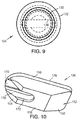
- FIG. 9 is a bottom view thereof.
- FIG. 10 is a perspective view of a first embodiment of a plug member for receipt in the receiver/jacket of FIG. 1 and retained by the retainer member of FIG. 7 .
- FIG. 11 is a top plan view of the plug member of FIG. 10 .
- FIG. 12 is a front view thereof.
- FIG. 13 is an end view taken from the left-hand side thereof.
- FIG. 14 is an end view taken from the right-hand side thereof.
- FIG. 15 is a cross-sectional view.
- FIG. 16 is a perspective view of a second receiver/jacket of a plug arrangement/plug assembly.
- FIG. 17 is another perspective view of the second receiver/jacket of FIG. 16 .
- FIG. 18 is a top plan view of the receiver/jacket of FIGS. 16-17 .
- FIG. 19 is a front elevational view thereof.
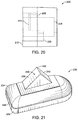
- FIG. 20 is a first end view taken generally from the right-hand side thereof.
- FIG. 21 is a perspective view of a second embodiment of a plug member for receipt in the receiver/jacket of FIGS. 16-20 and retained by a friction fit therein.
- FIG. 22 is a front view of the second plug member of FIG. 21 .
- FIG. 23 is a top plan view thereof.
- FIG. 24 is an end view taken generally from the right-hand side of FIG. 23 .
- FIGS. 25 and 26 are perspective views illustrating an alternative embodiment of the second receiver/jacket.
- FIGS. 27-31 are views of an alternative plug.
- FIGS. 32 and 33 show a preferred tool used for installation and removal of the plugs.
- FIGS. 1-15 there is shown a first embodiment of a plug assembly 100 that includes a receiver/jacket 102 ( FIGS. 1-6 ), a retainer member 104 ( FIGS. 7-9 ), and a first plug member 106 ( FIGS. 10-15 ).
- the receiver/jacket 102 of the plug assembly 100 is dimensioned for receipt in an associated recess of a mold such as a tire mold (not shown).
- the receiver/jacket 102 has a defined perimeter shape dimensioned for receipt in the associated similarly shaped recess of the tire mold.
- the receiver/jacket 102 as an outer, generally oval-shaped perimeter wall 110 , a base wall 112 , a wall/surface 114 , and a recess or cavity 116 defined by the wall 114 and a first surface 118 .
- the wall 114 has an irregular perimeter shape. Particularly the wall forms a generally D-shaped cavity 116 for reasons which will be described in greater detail below.
- Extending through the base wall 112 are first and second openings 120 , 122 .
- the first opening 120 is dimensioned to receive a fastener 124 ( FIG.
- the second opening 122 also extends from the first surface 118 and through the base wall 112 .
- the second opening 122 is dimensioned to receive the retainer 104 ( FIGS. 7-9 ), and particularly a stem 130 of the retainer. Shoulder 132 of the retainer 104 is dimensioned so that the shoulder cannot pass through the second opening 122 . Further, the retainer 104 includes an enlarged head 134 that preferably has a generally spherical or ball shape that interconnects with the shoulder 132 via reduced dimension neck 136 . A portion of the stem 130 is externally threaded so that a tool slot 138 in the head 134 can receive a tool (such as a flat blade of a conventional screwdriver—not shown) to advance the stem into threaded engagement with the second opening 122 .
- a tool such as a flat blade of a conventional screwdriver—not shown
- FIGS. 10-15 illustrate the removable, first plug 106 in greater detail.
- the first plug 106 has a generally D-shaped outer perimeter 150 that is dimensioned for a removable, press or friction fit in the cavity 116 of the receiver/jacket 102 .
- a first or rear face 152 includes first and second angled surfaces 154 , 156 extending inwardly from respective first and second ends of the plug 106 .
- Each of the angled surfaces 154 , 156 merge into planar surface 158 that is generally centrally located on the rear face 152 of the plug 106 .
- the plug 106 further includes a recess 170 that extends inwardly from the perimeter 150 of the plug, and the recess is dimensioned to receive the enlarged spherical head 134 of the retainer 104 therein.
- the angled surface 154 is oriented generally parallel to surface 118 that forms the cavity in the receiver/jacket 102 , and the recess 170 receives the spherical head 134 and reduced dimension neck 136 of the retainer 104 is dimensioned for sliding receipt beneath a U-shaped undercut edge 172 that partially forms the recess.
- the curved, first end of the plug is advanced into the cavity of the receiver/jacket 102 , and the undercut edge 172 is slidably received over the neck 136 and the enlarged spherical head 134 prevents inadvertent removal of the plug outwardly from the receiver/jacket cavity in a direction perpendicular to surface 118 thereof, i.e., in a direction parallel to the axis of the retainer stem 130 .
- the contour of the recess 170 includes partial spheroidal portions 174 that conform to the outer surface of the enlarged spherical head 134 of the retainer 104 ( FIGS. 13-14 ).
- the plug 106 has been tilted so that planar surface 158 of the plug is disposed in planar, mating contact with the surface 118 of the receiver/jacket.
- the curved end of the plug 106 mates with the curved end of the recess 116 in the receiver/jacket 102 (that is, the plug can only be inserted into the jacket recess in one direction whereby the curved ends are aligned).
- any desired indicia e.g., date information such as numerical representations of the day/month/year can be provided (e.g., engraved) on the second face 178 of the plug 106 so that the desired information is formed in the surface of the molded product (e.g. tire). Since the mold will be used for an extended period of time, it is then necessary to periodically remove the plug 106 so that the information provided by the indicia and molded into the product is kept up-to-date.
- the first plug 106 may be removed weekly and a new first plug with up-to-date indicia installed before the production run of a particular week.
- FIGS. 16-20 show a second receiver/jacket 200 that is provided for use in connection with the mold (not shown).
- the second receiver/jacket 200 has an external perimeter 202 that mates with a suitably shaped recess (not shown) in the mold (not shown).
- the second receiver/jacket 200 is secured in the mold recess via a fastener (e.g., a fastener such as a threaded cap screw) configured for receipt through opening 204 in a recessed surface 206 that forms, at least in part, the lower boundary of a cavity 208 that is generally D-shaped and receives a correspondingly D-shaped second plug (to be described further below).
- a fastener e.g., a fastener such as a threaded cap screw
- the support member 212 Extending upwardly from the recess surface 206 toward outer face 210 is a support member 212 .
- the support member 212 is generally centrally located along one side of the cavity 208 and generally bisects the cavity in a longitudinal direction.
- the support member 212 includes an upper, planar surface 214 that includes chamfered edges 216 , 218 on opposite ends thereof. Additionally, a channel 220 extends along the opposite side of the cavity 208 and is recessed further than surface 206 .
- a second plug 230 ( FIGS. 21-24 ) has an external perimeter 232 that is generally D-shaped for mating receipt in the cavity 208 of the second receiver/jacket 200 .
- the second plug 230 includes a lower, first face 234 that is intended to face into the cavity of the second receiver/jacket 200 .
- a protrusion 236 extends outwardly from the face 234 and is dimensioned for receipt in the channel 220 .
- the protrusion 236 has a generally triangular-shaped contour defined by angled faces 238 , 240 and a vertex 242 defined by the intersection of these angled faces ( FIG. 22 ).
- the vertex 242 in combination with the chamfered edges 216 , 218 of the support member 212 allow for a selective pivoting or rocking of the second plug 230 when a downward force is applied to an upper, second face 244 of the second plug.
- the protrusion also angles inwardly from a perimeter edge 202 of the second plug 230 as particularly illustrated in FIG. 24 , again to facilitate insertion and removal of the second plug from the associated receiver 200 .
- the D-shaped perimeter 232 of the second plug 230 only permits a singular orientation of the second plug into the D-shaped cavity 208 second receiver/jacket 200 .
- the protrusion 236 is aligned over the channel 220 in this orientation and the face 234 of the second plug abuts against surface 214 of the support member 212 .
- Dimensioning of the outer perimeter 232 of the second plug 230 in the cavity 208 provides a tight friction fit that retains the second plug in place.
- the second face 244 of the second plug may also be provided with indicia thereon (in reverse) that will provide additional, required information on the molded product (e.g. tire).
- this additional information may relate to identifying information of the particular mold whereby the manufacturer can determine the particular mold in which a specific tire was vulcanized.
- FIGS. 25-26 show a revised second receiver or jacket 200 ′.
- like reference numerals with a primed suffix (′) will be used to refer to like components (e.g., second receiver 200 ′ in FIGS. 25-26 correlate to the description of the first embodiment of the second receiver/jacket 200 set forth in connection with FIGS. 16-20 ) and the previous description applies to the second embodiment of FIGS. 25-26 unless specifically noted otherwise.
- New reference numerals will be used to identify new components/features.
- the primary change is associated with the support member 214 ′ and the elevation of a portion 276 of the recess surface 206 ′.
- the second plug By raising the recess surface portion 276 , the second plug will not be permitted to tilt or pivot on the support member 214 ′ in a direction toward the opening 204 ′. Specifically, the second plug will tip out in only one direction, i.e., along the chamfer 218 ′ (since chamfer 216 of FIGS. 16-20 has been eliminated by raising the height of portion 276 of the recess surface 206 ′). In substantially all other respects, the second embodiment of the second receiver 200 ′ is the same.
- FIGS. 27-31 A second embodiment of an alternative plug is shown in FIGS. 27-31 and is substantially similar to the first embodiment of the plug, and particularly similar to FIGS. 10-15 .
- the removable plug 106 ′ has a generally D-shaped outer perimeter 150 ′ that is likewise dimensioned for a removable, press or friction fit in the cavity 116 of the receiver/jacket 102 .
- a primary difference is the modification or elimination of angled surface 154 as used in the embodiment of FIGS. 10-15 . Instead, the surface 154 ′ extends generally perpendicular (i.e., is not as acutely angled) from planar surface 158 ′.
- Surface 156 ′ is still angled in the same manner as the earlier embodiment, and extends inwardly from its associated end of the plug 106 ′.
- Planar surface 158 ′ is generally centrally located on the rear face 152 ′ of the plug 106 ′.
- the plug 106 ′ further includes a recess 170 ′ that extends inwardly from the perimeter 150 of the plug, and the recess is dimensioned to receive the enlarged spherical head 134 of the retainer 104 therein.
- the alternative plug 106 ′ of FIGS. 27-31 is structurally and functionally similar to that shown and described in connection with FIGS. 10-14 .
- the tip out plug tool 250 includes a first end 252 and a distal second end 254 .
- the first end 252 includes a bulbous member 256 that is adapted to facilitate gripping of the tool 250 by a user while controlling the distal second end 254 of the tool.
- the bulbous member 256 may also be advantageously employed as a mallet for providing a striking force to another object.
- the bulbous number 256 is formed from a thermoplastic such as polyoxymethylene (POM) more commonly referred to as acetyl, polyacetyl, or polyformaldehyde to prevent damage to the mold if the bulbous member is used as a mallet.
- the distal second end 254 of the tool 250 preferably includes a biased or spring-loaded center punch.
- the spring-loaded center punch includes an end tip 258 formed from the POM described above or another similar material that minimizes scratching and/or damage to the mold, such as brass for example.
- the pointed tip 258 is preferably located on a striking surface of the center punch and at the very end where the tip is adapted to engage the upper surface of the first plug or the second plug and thereby minimize any slipping of the end tip relative to the first or second plug when employing the tool to remove one of the plugs from their respective receiver/jacket.
- the first and second plug assemblies described above and their associated jacket/receivers are designed to make installation and removal of the plugs easier and faster.
- Current style plugs are removed with a hammer and punch which can lead to damaging the sidewall of the tire mold, for example.
- the first and second plugs described above are designed to be installed and removed without a hammer and punch thus substantially reducing the potential for damaging the sidewall of the tire mold.
- the first and second plugs are also designed to prevent the plug from being installed improperly in the tire mold.
- the first plug assembly includes the receiver/jacket with a corresponding D-shaped cavity to receive the D-shaped first plug.
- the first receiver/jacket includes a first opening and an adjacent second opening formed therethrough in a bottom surface.
- the first opening receives a fastener to attach the receiver/jacket to a tire mold.
- the second opening is adapted to receive and secure a retaining member within the cavity of the first receiver/jacket.
- a taper is preferably formed on an opposite end of the lower surface of the first plug to facilitate removal of the first plug from the first receiver/jacket.
- the second plug assembly includes a second receiver/jacket also having a D-shaped opening to receive the correspondingly shaped D-shaped second plug.
- the second receiver/jacket and the second plug are designed to provide a friction fit to facilitate retention of the second plug within the cavity of the second receiver/jacket.
- the second receiver/jacket includes an opening formed therethrough in a bottom surface that is adapted to receive a fastener for attaching the second receiver/jacket to a tire mold.
- a channel is formed in a bottom surface of the cavity to limit the orientation of the receiver and plug relative to one another to a single orientation and thereby minimize a likelihood of improperly inserting the second plug in an undesired orientation relative to the second receiver/jacket.
- the support member is formed in the surface of the receiver/jacket.
- the support member is located within the cavity and provides a fulcrum point for tipping the triangular-shaped plug portion relative to the receiver/jacket to facilitate removal of the plug from the receiver/jacket.
- the second plug includes an upper surface for engraving desired indicia thereon. Adjacent one edge of the lower face of the second plug is a triangular-shaped protrusion. The triangular-shaped protrusion is received in the channel formed in the cavity of the receiver/jacket.
- Each of the first and second plugs minimize the potential that one of the plugs and receivers/jackets will be improperly inserted into its desired location of the tire mold. This assures that the date code plug will be inserted into the proper location in the mold while the curing press information will be likewise inserted into its proper location in the tire mold.
- the first and second receivers/jackets of the first and second plugs will not readily accept the other style of plug. Moreover, by providing a plug tool for installation and removal of the plugs, excessive force or hammering will be avoided.
Landscapes
- Engineering & Computer Science (AREA)
- Mechanical Engineering (AREA)
- Moulds For Moulding Plastics Or The Like (AREA)
- Heating, Cooling, Or Curing Plastics Or The Like In General (AREA)
Abstract
Description
Claims (22)
Priority Applications (1)
| Application Number | Priority Date | Filing Date | Title |
|---|---|---|---|
| US16/608,659 US11220078B2 (en) | 2017-04-26 | 2018-04-26 | Ball hitch tip out plug, triangle leg tip out plug, combination, and tip out plug tool |
Applications Claiming Priority (3)
| Application Number | Priority Date | Filing Date | Title |
|---|---|---|---|
| US201762490311P | 2017-04-26 | 2017-04-26 | |
| PCT/US2018/029592 WO2018200828A1 (en) | 2017-04-26 | 2018-04-26 | Ball hitch tip out plug, triangle leg tip out plug, combination, and tip out plug tool |
| US16/608,659 US11220078B2 (en) | 2017-04-26 | 2018-04-26 | Ball hitch tip out plug, triangle leg tip out plug, combination, and tip out plug tool |
Publications (2)
| Publication Number | Publication Date |
|---|---|
| US20200180250A1 US20200180250A1 (en) | 2020-06-11 |
| US11220078B2 true US11220078B2 (en) | 2022-01-11 |
Family
ID=63920097
Family Applications (1)
| Application Number | Title | Priority Date | Filing Date |
|---|---|---|---|
| US16/608,659 Expired - Fee Related US11220078B2 (en) | 2017-04-26 | 2018-04-26 | Ball hitch tip out plug, triangle leg tip out plug, combination, and tip out plug tool |
Country Status (8)
| Country | Link |
|---|---|
| US (1) | US11220078B2 (en) |
| EP (1) | EP3615293B1 (en) |
| JP (1) | JP7100060B2 (en) |
| KR (1) | KR102509806B1 (en) |
| CN (1) | CN110785273B (en) |
| MX (1) | MX2019012816A (en) |
| RS (2) | RS20191388A1 (en) |
| WO (1) | WO2018200828A1 (en) |
Families Citing this family (2)
| Publication number | Priority date | Publication date | Assignee | Title |
|---|---|---|---|---|
| JP7293041B2 (en) * | 2019-08-20 | 2023-06-19 | Toyo Tire株式会社 | Tire mold and tire manufacturing method |
| CN118176106A (en) * | 2021-11-04 | 2024-06-11 | 倍耐力轮胎股份公司 | Method and actuating device for applying an insert to a vulcanization mold and process for producing wheel tires using the vulcanization mold |
Citations (19)
| Publication number | Priority date | Publication date | Assignee | Title |
|---|---|---|---|---|
| US1567402A (en) * | 1922-05-17 | 1925-12-29 | Century Rubber Works | Tire mold |
| US2296016A (en) * | 1940-11-12 | 1942-09-15 | Akron Standard Mold Co | Tire mold |
| US2679663A (en) * | 1950-02-01 | 1954-06-01 | Goodrich Co B F | Marking of molded articles |
| US3100318A (en) * | 1959-04-07 | 1963-08-13 | Firestone Tire & Rubber Co | Mold identification plug |
| US3407499A (en) | 1966-06-06 | 1968-10-29 | American Toy And Furniture Co | Tapping tool |
| US3734448A (en) * | 1971-04-29 | 1973-05-22 | Freeman Supply Co | Quick change indicia for patterns and the like |
| JPS5041615A (en) * | 1973-03-02 | 1975-04-16 | ||
| US4547139A (en) | 1984-12-17 | 1985-10-15 | The Goodyear Tire & Rubber Company | Tire mold |
| US5939002A (en) | 1997-04-16 | 1999-08-17 | Michelin Recherche Et Technique S.A. | Apparatus and process for changing a sidewall insert of a tire mold |
| EP1136217A2 (en) | 2000-03-14 | 2001-09-26 | Société de Technologie Michelin | Quick release device for a tire mold plate |
| US6308929B1 (en) * | 1998-10-22 | 2001-10-30 | Klaus A. Wieder | Mold insert |
| US6942476B2 (en) | 2002-08-15 | 2005-09-13 | The Goodyear Tire & Rubber Company | Method and apparatus for changing tire identification means via magnetic inserts |
| JP2006001224A (en) | 2004-06-21 | 2006-01-05 | Yokohama Rubber Co Ltd:The | Mold for rubber vulcanization |
| CN101314249A (en) | 2007-05-29 | 2008-12-03 | 东洋橡胶工业株式会社 | Tire tread vulcanization mold |
| US7883326B1 (en) | 2010-01-27 | 2011-02-08 | The Goodyear Tire & Rubber Company | Apparatus and assembly for interchanging indicia of tire molds |
| US20110180200A1 (en) | 2010-01-27 | 2011-07-28 | James Richard Parmelee | Method for interchanging indicia of tire molds |
| DE102010017251A1 (en) * | 2010-06-07 | 2011-12-08 | Continental Reifen Deutschland Gmbh | Device for vulcanization of vehicle tire, has replaceable plunger for embossing characters in side wall of tire preform and demountable from side panel of mold without loosening panel from components of mold |
| US20170014883A1 (en) | 2015-07-17 | 2017-01-19 | Edgy Tools LLC | Hand-held punch tool |
| US9597849B2 (en) | 2013-08-05 | 2017-03-21 | Compagnie Generale Des Etablissements Michelin | Mold for tire having a removable annular insert |
Family Cites Families (17)
| Publication number | Priority date | Publication date | Assignee | Title |
|---|---|---|---|---|
| US3739662A (en) * | 1971-01-15 | 1973-06-19 | Matthews J & Co | Retread tire marking method and apparatus |
| CA1076012A (en) * | 1978-05-23 | 1980-04-22 | William Reichenbach | Tire plug for tubeless tires |
| US5288449A (en) * | 1992-06-24 | 1994-02-22 | Mauro Charles R | Device and method for personalizing tires |
| EP0576892B1 (en) * | 1992-07-02 | 1996-01-10 | Compagnie Generale Des Etablissements Michelin-Michelin & Cie | Tire mould, manufacturing process for such a mould and tire molding process using such a mould |
| KR100540244B1 (en) | 2003-06-25 | 2006-01-10 | 한국타이어 주식회사 | Dial Joiner of Tire Mold |
| JP2005161546A (en) * | 2003-11-28 | 2005-06-23 | Yokohama Rubber Co Ltd:The | Tire vulcanization mold |
| BRPI0721852B1 (en) | 2007-07-11 | 2018-05-22 | Pirelli Tyre S.P.A. | APPARATUS AND PROCESS FOR MOLDING AND TREATING TIRES |
| JP2011031519A (en) | 2009-08-03 | 2011-02-17 | Bridgestone Corp | Mold for vulcanization |
| CN201592499U (en) * | 2009-09-28 | 2010-09-29 | 青岛联鑫机械有限公司 | Tyre wall plate of tyre segmental mold |
| CN102299434A (en) * | 2010-06-25 | 2011-12-28 | 上海市闸北区和田路小学 | Reinforced connector |
| JP5576415B2 (en) * | 2012-02-14 | 2014-08-20 | パナソニック株式会社 | Film-in-mold injection mold apparatus and molding method using the same |
| FR3009228B1 (en) * | 2013-08-05 | 2015-08-21 | Michelin & Cie | PNEUMATIC MOLD COMPRISING AN ANNULAR INSERT IN SEVERAL PARTS |
| JP6179921B2 (en) * | 2013-09-09 | 2017-08-16 | 東洋ゴム工業株式会社 | Indicating stamp plate, tire vulcanizing mold and tire |
| KR101570803B1 (en) * | 2014-02-19 | 2015-11-20 | 주식회사 엠케이테크놀로지 | Tread of the tire mold |
| FR3020593B1 (en) * | 2014-04-30 | 2016-12-23 | Michelin & Cie | MOLD ELEMENT FOR PNEUMATIC MOLD COMPRISING A MARKING |
| CN205044059U (en) * | 2015-08-13 | 2016-02-24 | 昆山明炜精密模具有限公司 | Injection mold |
| CN105082405B (en) * | 2015-08-13 | 2017-07-28 | 青岛金科模具有限公司 | The tire-mold side plate of fast changeable type block |
-
2018
- 2018-04-26 RS RS20191388A patent/RS20191388A1/en unknown
- 2018-04-26 JP JP2019558596A patent/JP7100060B2/en not_active Expired - Fee Related
- 2018-04-26 CN CN201880042498.4A patent/CN110785273B/en not_active Expired - Fee Related
- 2018-04-26 WO PCT/US2018/029592 patent/WO2018200828A1/en not_active Ceased
- 2018-04-26 US US16/608,659 patent/US11220078B2/en not_active Expired - Fee Related
- 2018-04-26 KR KR1020197033809A patent/KR102509806B1/en active Active
- 2018-04-26 MX MX2019012816A patent/MX2019012816A/en unknown
- 2018-04-26 RS RS20220189A patent/RS63005B1/en unknown
- 2018-04-26 EP EP18790092.3A patent/EP3615293B1/en not_active Not-in-force
Patent Citations (21)
| Publication number | Priority date | Publication date | Assignee | Title |
|---|---|---|---|---|
| US1567402A (en) * | 1922-05-17 | 1925-12-29 | Century Rubber Works | Tire mold |
| US2296016A (en) * | 1940-11-12 | 1942-09-15 | Akron Standard Mold Co | Tire mold |
| US2679663A (en) * | 1950-02-01 | 1954-06-01 | Goodrich Co B F | Marking of molded articles |
| US3100318A (en) * | 1959-04-07 | 1963-08-13 | Firestone Tire & Rubber Co | Mold identification plug |
| US3407499A (en) | 1966-06-06 | 1968-10-29 | American Toy And Furniture Co | Tapping tool |
| US3734448A (en) * | 1971-04-29 | 1973-05-22 | Freeman Supply Co | Quick change indicia for patterns and the like |
| JPS5041615A (en) * | 1973-03-02 | 1975-04-16 | ||
| US4547139A (en) | 1984-12-17 | 1985-10-15 | The Goodyear Tire & Rubber Company | Tire mold |
| US5939002A (en) | 1997-04-16 | 1999-08-17 | Michelin Recherche Et Technique S.A. | Apparatus and process for changing a sidewall insert of a tire mold |
| US6308929B1 (en) * | 1998-10-22 | 2001-10-30 | Klaus A. Wieder | Mold insert |
| EP1136217A2 (en) | 2000-03-14 | 2001-09-26 | Société de Technologie Michelin | Quick release device for a tire mold plate |
| US6315539B1 (en) * | 2000-03-14 | 2001-11-13 | Michelin Rechereche Et Technique S.A. | Quick release device for a tire mold plate |
| US6942476B2 (en) | 2002-08-15 | 2005-09-13 | The Goodyear Tire & Rubber Company | Method and apparatus for changing tire identification means via magnetic inserts |
| JP2006001224A (en) | 2004-06-21 | 2006-01-05 | Yokohama Rubber Co Ltd:The | Mold for rubber vulcanization |
| CN101314249A (en) | 2007-05-29 | 2008-12-03 | 东洋橡胶工业株式会社 | Tire tread vulcanization mold |
| US7670124B2 (en) | 2007-05-29 | 2010-03-02 | Toyo Tire & Rubber Co., Ltd. | Metal mold for vulcanizing tire treads |
| US7883326B1 (en) | 2010-01-27 | 2011-02-08 | The Goodyear Tire & Rubber Company | Apparatus and assembly for interchanging indicia of tire molds |
| US20110180200A1 (en) | 2010-01-27 | 2011-07-28 | James Richard Parmelee | Method for interchanging indicia of tire molds |
| DE102010017251A1 (en) * | 2010-06-07 | 2011-12-08 | Continental Reifen Deutschland Gmbh | Device for vulcanization of vehicle tire, has replaceable plunger for embossing characters in side wall of tire preform and demountable from side panel of mold without loosening panel from components of mold |
| US9597849B2 (en) | 2013-08-05 | 2017-03-21 | Compagnie Generale Des Etablissements Michelin | Mold for tire having a removable annular insert |
| US20170014883A1 (en) | 2015-07-17 | 2017-01-19 | Edgy Tools LLC | Hand-held punch tool |
Non-Patent Citations (2)
| Title |
|---|
| First Notification of Office Action dated May 19, 2021 issued by China National Intellectual Property Administration for Application No. 201880042498.4 (with English explanation). |
| PCT/US2018/029592 International Search Report, Written Opinion, dated Aug. 27, 2018. |
Also Published As
| Publication number | Publication date |
|---|---|
| RS20191388A1 (en) | 2020-05-29 |
| US20200180250A1 (en) | 2020-06-11 |
| CN110785273B (en) | 2022-04-08 |
| EP3615293A4 (en) | 2021-01-20 |
| KR102509806B1 (en) | 2023-03-13 |
| EP3615293A1 (en) | 2020-03-04 |
| MX2019012816A (en) | 2020-01-14 |
| WO2018200828A1 (en) | 2018-11-01 |
| CN110785273A (en) | 2020-02-11 |
| RS63005B1 (en) | 2022-03-31 |
| EP3615293B1 (en) | 2022-01-05 |
| KR20190141185A (en) | 2019-12-23 |
| JP2020517499A (en) | 2020-06-18 |
| JP7100060B2 (en) | 2022-07-12 |
Similar Documents
| Publication | Publication Date | Title |
|---|---|---|
| CN102666141B (en) | Anti-skid stud | |
| US11220078B2 (en) | Ball hitch tip out plug, triangle leg tip out plug, combination, and tip out plug tool | |
| US20070258795A1 (en) | Parts attaching structure | |
| US20080080937A1 (en) | Cutting Tool Having Cutting Insert Secured By Non-Penetrating Abutment of a Threaded Fastener | |
| JPH067837B2 (en) | Implant for osteosynthesis device and its attachment device | |
| JPH0631504A (en) | Cutting tool with insert and spacer | |
| GB2082245A (en) | Angle or ball joint | |
| US5516241A (en) | Holder blade | |
| US5960682A (en) | Plug wrench | |
| CZ298864B6 (en) | Unitary, plastic, snap-on overcap of a container | |
| CN102422030A (en) | Fastener | |
| EP0338280B1 (en) | Writing instrument assembly and assembly method | |
| US20160013584A1 (en) | Structure of network connector | |
| US20110158769A1 (en) | Tanged screw thread insert with improved removability | |
| US10307832B2 (en) | Dynamic clamping mechanism | |
| US1927844A (en) | Socket wrench | |
| US3400443A (en) | Method of at least partially removing a tire stud from a tire | |
| CN110854606A (en) | Buckle structure and casing | |
| EP0193679B1 (en) | Snap-in anchor for denture | |
| US5083841A (en) | Wheel cover mounting assembly | |
| JP4479972B2 (en) | Small flag wrench, small flag wrench wrench member and small flag wrench knob member | |
| US2031880A (en) | Bottle stopper | |
| US20010053318A1 (en) | Male screw | |
| JP3049187U (en) | Screwdriver bit with screw head holder and screw head holder | |
| JPH0871809A (en) | Grooving tool, tool holder, and throw-away tip |
Legal Events
| Date | Code | Title | Description |
|---|---|---|---|
| FEPP | Fee payment procedure |
Free format text: ENTITY STATUS SET TO UNDISCOUNTED (ORIGINAL EVENT CODE: BIG.); ENTITY STATUS OF PATENT OWNER: LARGE ENTITY |
|
| STPP | Information on status: patent application and granting procedure in general |
Free format text: NON FINAL ACTION MAILED |
|
| STPP | Information on status: patent application and granting procedure in general |
Free format text: RESPONSE TO NON-FINAL OFFICE ACTION ENTERED AND FORWARDED TO EXAMINER |
|
| AS | Assignment |
Owner name: COOPER TIRE & RUBBER COMPANY, OHIO Free format text: ASSIGNMENT OF ASSIGNORS INTEREST;ASSIGNORS:REIGLE, STEVE;ACKERMAN, CHRIS;BADERTSCHER, BRETT;AND OTHERS;REEL/FRAME:056639/0676 Effective date: 20170517 |
|
| STPP | Information on status: patent application and granting procedure in general |
Free format text: FINAL REJECTION MAILED |
|
| STPP | Information on status: patent application and granting procedure in general |
Free format text: RESPONSE AFTER FINAL ACTION FORWARDED TO EXAMINER |
|
| STPP | Information on status: patent application and granting procedure in general |
Free format text: NOTICE OF ALLOWANCE MAILED -- APPLICATION RECEIVED IN OFFICE OF PUBLICATIONS |
|
| STPP | Information on status: patent application and granting procedure in general |
Free format text: PUBLICATIONS -- ISSUE FEE PAYMENT VERIFIED |
|
| STCF | Information on status: patent grant |
Free format text: PATENTED CASE |
|
| AS | Assignment |
Owner name: GOODYEAR TIRE & RUBBER COMPANY, THE, OHIO Free format text: ASSIGNMENT OF ASSIGNORS INTEREST;ASSIGNOR:COOPER TIRE & RUBBER COMPANY;REEL/FRAME:062354/0046 Effective date: 20221116 |
|
| FEPP | Fee payment procedure |
Free format text: MAINTENANCE FEE REMINDER MAILED (ORIGINAL EVENT CODE: REM.); ENTITY STATUS OF PATENT OWNER: LARGE ENTITY |
|
| LAPS | Lapse for failure to pay maintenance fees |
Free format text: PATENT EXPIRED FOR FAILURE TO PAY MAINTENANCE FEES (ORIGINAL EVENT CODE: EXP.); ENTITY STATUS OF PATENT OWNER: LARGE ENTITY |
|
| STCH | Information on status: patent discontinuation |
Free format text: PATENT EXPIRED DUE TO NONPAYMENT OF MAINTENANCE FEES UNDER 37 CFR 1.362 |
|
| FP | Lapsed due to failure to pay maintenance fee |
Effective date: 20260111 |