US11219477B2 - Instrument for attaching to a bone anchor and instrument for use in distraction and/or retraction, in particular for orthopedic surgery or neurosurgery, more specifically for spinal surgery - Google Patents
Instrument for attaching to a bone anchor and instrument for use in distraction and/or retraction, in particular for orthopedic surgery or neurosurgery, more specifically for spinal surgery Download PDFInfo
- Publication number
- US11219477B2 US11219477B2 US16/577,961 US201916577961A US11219477B2 US 11219477 B2 US11219477 B2 US 11219477B2 US 201916577961 A US201916577961 A US 201916577961A US 11219477 B2 US11219477 B2 US 11219477B2
- Authority
- US
- United States
- Prior art keywords
- arm
- head
- instrument
- section
- blade
- Prior art date
- Legal status (The legal status is an assumption and is not a legal conclusion. Google has not performed a legal analysis and makes no representation as to the accuracy of the status listed.)
- Active, expires
Links
Images


Classifications
-
- A—HUMAN NECESSITIES
- A61—MEDICAL OR VETERINARY SCIENCE; HYGIENE
- A61B—DIAGNOSIS; SURGERY; IDENTIFICATION
- A61B17/00—Surgical instruments, devices or methods, e.g. tourniquets
- A61B17/56—Surgical instruments or methods for treatment of bones or joints; Devices specially adapted therefor
- A61B17/58—Surgical instruments or methods for treatment of bones or joints; Devices specially adapted therefor for osteosynthesis, e.g. bone plates, screws, setting implements or the like
- A61B17/88—Osteosynthesis instruments; Methods or means for implanting or extracting internal or external fixation devices
- A61B17/8872—Instruments for putting said fixation devices against or away from the bone
-
- A—HUMAN NECESSITIES
- A61—MEDICAL OR VETERINARY SCIENCE; HYGIENE
- A61B—DIAGNOSIS; SURGERY; IDENTIFICATION
- A61B17/00—Surgical instruments, devices or methods, e.g. tourniquets
- A61B17/02—Surgical instruments, devices or methods, e.g. tourniquets for holding wounds open; Tractors
- A61B17/0206—Surgical instruments, devices or methods, e.g. tourniquets for holding wounds open; Tractors with antagonistic arms as supports for retractor elements
-
- A—HUMAN NECESSITIES
- A61—MEDICAL OR VETERINARY SCIENCE; HYGIENE
- A61B—DIAGNOSIS; SURGERY; IDENTIFICATION
- A61B17/00—Surgical instruments, devices or methods, e.g. tourniquets
- A61B17/02—Surgical instruments, devices or methods, e.g. tourniquets for holding wounds open; Tractors
- A61B17/0218—Surgical instruments, devices or methods, e.g. tourniquets for holding wounds open; Tractors for minimally invasive surgery
-
- A—HUMAN NECESSITIES
- A61—MEDICAL OR VETERINARY SCIENCE; HYGIENE
- A61B—DIAGNOSIS; SURGERY; IDENTIFICATION
- A61B17/00—Surgical instruments, devices or methods, e.g. tourniquets
- A61B17/56—Surgical instruments or methods for treatment of bones or joints; Devices specially adapted therefor
- A61B17/58—Surgical instruments or methods for treatment of bones or joints; Devices specially adapted therefor for osteosynthesis, e.g. bone plates, screws, setting implements or the like
- A61B17/68—Internal fixation devices, including fasteners and spinal fixators, even if a part thereof projects from the skin
- A61B17/70—Spinal positioners or stabilisers ; Bone stabilisers comprising fluid filler in an implant
- A61B17/7074—Tools specially adapted for spinal fixation operations other than for bone removal or filler handling
- A61B17/7076—Tools specially adapted for spinal fixation operations other than for bone removal or filler handling for driving, positioning or assembling spinal clamps or bone anchors specially adapted for spinal fixation
- A61B17/7077—Tools specially adapted for spinal fixation operations other than for bone removal or filler handling for driving, positioning or assembling spinal clamps or bone anchors specially adapted for spinal fixation for moving bone anchors attached to vertebrae, thereby displacing the vertebrae
-
- A—HUMAN NECESSITIES
- A61—MEDICAL OR VETERINARY SCIENCE; HYGIENE
- A61B—DIAGNOSIS; SURGERY; IDENTIFICATION
- A61B1/00—Instruments for performing medical examinations of the interior of cavities or tubes of the body by visual or photographical inspection, e.g. endoscopes; Illuminating arrangements therefor
- A61B1/32—Devices for opening or enlarging the visual field, e.g. of a tube of the body
-
- A—HUMAN NECESSITIES
- A61—MEDICAL OR VETERINARY SCIENCE; HYGIENE
- A61B—DIAGNOSIS; SURGERY; IDENTIFICATION
- A61B17/00—Surgical instruments, devices or methods, e.g. tourniquets
- A61B17/00234—Surgical instruments, devices or methods, e.g. tourniquets for minimally invasive surgery
- A61B2017/00353—Surgical instruments, devices or methods, e.g. tourniquets for minimally invasive surgery one mechanical instrument performing multiple functions, e.g. cutting and grasping
-
- A—HUMAN NECESSITIES
- A61—MEDICAL OR VETERINARY SCIENCE; HYGIENE
- A61B—DIAGNOSIS; SURGERY; IDENTIFICATION
- A61B17/00—Surgical instruments, devices or methods, e.g. tourniquets
- A61B17/02—Surgical instruments, devices or methods, e.g. tourniquets for holding wounds open; Tractors
- A61B17/025—Joint distractors
- A61B2017/0256—Joint distractors for the spine
-
- A—HUMAN NECESSITIES
- A61—MEDICAL OR VETERINARY SCIENCE; HYGIENE
- A61B—DIAGNOSIS; SURGERY; IDENTIFICATION
- A61B17/00—Surgical instruments, devices or methods, e.g. tourniquets
- A61B17/32—Surgical cutting instruments
- A61B17/3209—Incision instruments
- A61B17/3211—Surgical scalpels, knives; Accessories therefor
- A61B2017/32113—Surgical scalpels, knives; Accessories therefor with extendable or retractable guard or blade
-
- A—HUMAN NECESSITIES
- A61—MEDICAL OR VETERINARY SCIENCE; HYGIENE
- A61B—DIAGNOSIS; SURGERY; IDENTIFICATION
- A61B17/00—Surgical instruments, devices or methods, e.g. tourniquets
- A61B17/56—Surgical instruments or methods for treatment of bones or joints; Devices specially adapted therefor
- A61B17/58—Surgical instruments or methods for treatment of bones or joints; Devices specially adapted therefor for osteosynthesis, e.g. bone plates, screws, setting implements or the like
- A61B17/88—Osteosynthesis instruments; Methods or means for implanting or extracting internal or external fixation devices
- A61B17/92—Impactors or extractors, e.g. for removing intramedullary devices
- A61B2017/922—Devices for impaction, impact element
- A61B2017/924—Impact element driving means
- A61B2017/925—Impact element driving means a spring
Definitions
- the application relates to an instrument for attaching to a bone anchor, more specifically to a retractor blade for attaching to a bone anchor, and to an instrument for use in distraction and/or retraction, in particular for orthopedic surgery or neurosurgery, more specifically for spinal surgery.
- Distraction and compression steps during spinal surgery are well-known in the art.
- cages, pedicle screws and rods are often used for providing stability to the spinal segments.
- the vertebrae are distracted, i.e., their distance relative to each other is increased. This is accomplished by using, for example, distraction pliers that engage two adjacent pedicle screws along a rod captured therein and spread them apart from each other. Thereby, the intervertebral space is enlarged.
- Documents DE 10 2016 110 706 A1 and US 2016/0106408 A1 describe instruments for use in spinal surgery that can be used for distraction and tissue retraction.
- MIS minimally invasive surgery
- known techniques for distraction and/or retraction in some cases may involve difficulties in attaching or holding the instruments while performing distraction and/or retraction steps.
- an instrument for attaching to a bone anchor includes an elongate portion and an end portion for connecting to a head of a bone anchoring element.
- the end portion is configured to accommodate at least a portion of the head of the bone anchoring element, and includes a first section configured to permit placement of the instrument onto and removal of the instrument from the head, and that further includes a second section that is configured to prevent removal of the instrument from the head.
- the instrument is a retractor blade.
- the retractor blade is not limited to the function of retracting soft tissue or muscles, but the term retractor blade also includes the possibilities that the blade can be adapted to be used for distraction, compression, and other steps in surgery.
- An advantage of the instrument, and more specifically the retractor blade is that it is attachable to a preferably spherically-shaped head of a bone anchoring element. Hence, the surgical steps can be carried out while the instrument that is used for carrying out the surgical steps is safely attached. Also, the visibility at the surgical site is improved if the retractor blade is attachable to a head of a bone anchoring element that protrudes out of the bone, compared to the case in which a polyaxial receiving part is connected to the bone anchoring element.
- an instrument for distraction and/or retraction includes at least two retractor blades that are mountable to respective arms attached to a frame, such as a positioning rod.
- the retractor blade or the instrument can be attached to the heads, in particular to the spherically-shaped heads of pedicle screws or other bone screws that are inserted into the pedicles or bone parts, prior to mounting the receiving parts for polyaxially connecting the screws to a rod.
- the retractor blade is designed such that the step of locating the head of the screw and attaching the retractor blade to the head is more easily facilitated. Therefore, the retractor blade or the instrument is suitable even under surgical conditions with poor visibility and little available space, such as in the case of minimally invasive surgery. Moreover, the attachment is also secure, where unwanted detachment is impeded.
- the retractor blade and instrument is not limited to MIS, but can also be used for open surgery.
- the attachment of the head to the end portion of the retractor blade is assisted by a spring force.
- the attachment step may include a vertical and thereafter a lateral movement of the end portion of the retractor blade relative to the head.
- the detachment step may include a lateral movement and thereafter a vertical movement of the end portion of the retractor blade relative to the head. This increases the safety against inadvertent removal of the retractor blade.
- the retractor blades are mounted to the arms of the instrument in such a manner that blade portions of the first retractor blade and the second retractor blade form a predefined angle, for example an angle of about 90° or exactly 90°.
- the predetermined angle formed by the retractor blades ensures that soft tissue can be retracted in a simple manner to enlarge the space and enhance the visibility at the surgical site.
- the retractor blade includes a seat for pivotably holding the head. This allows adapting of the orientation of the retractor blade to positions of the screw.
- the retractor blade is pivotable in a single plane relative to the arm of the instrument to allow adjustments of the position of the arm and the frame with respect to the retractor blade.
- the retractor blade may be locked relative to the arm at a desired angle. This allows adapting of the orientation of the retractor blade relative to the arm to cope with varying geometrical situations at the surgical site.
- the arms of the instrument can assume a straight configuration or an angled configuration, each of which may be locked. This allows the frame to assume an angle with respect to a plane defined by the portions of the arms, respectively, that are mounted to the retractor blades. By means of this, the frame can be held at a position that is closer to a patient's body during surgery.
- a third retractor blade is provided for the instrument that may be arranged on the frame between the arms and that may be movable in a direction substantially perpendicular to the direction in which the arms can move relative to each other on the frame.
- At least the first and second retractor blades, and preferably also the third retractor blade include blade portions that can be interchanged with other blade portions of different sizes, in particular of different lengths. This permits adapting of the instrument to specific situations and dimensions at the surgical site.
- the retractor blades can also be monolithic.
- the length of the retractor blades is adjustable.
- Embodiments of the invention also include bone anchoring elements having a shank for anchoring in bone and a head, wherein the head is preferably a spherical segment-shaped head.
- a method for distraction and/or retraction in particular for orthopedic surgery or neurosurgery, more specifically for spinal surgery, includes the steps of inserting shanks of a first and a second bone anchoring element in bone, for example in the pedicles of vertebrae, mounting the first retractor blade to a head of the first bone anchoring element by inserting the head into an end portion of the first retractor blade, mounting the second retractor blade to a head of the second bone anchoring element by inserting the head into an end portion of the second retractor blade, attaching a first arm to the first retractor blade and a second arm to the second retractor blade, wherein the first and the second arms are mounted on a frame, and optionally attaching a third retractor blade to the frame.
- the retractor blades are pivoted in a single plane with respect to the arms and may optionally be fixed at a specific pivot angle.
- the method may further include a step of distracting two vertebrae by moving the first retractor blade relative to the second retractor blade, thereby also retracting soft tissue with blade portions of the retractor blades.
- the instrument is removed from the bone anchoring elements.
- a receiving part for polyaxially coupling the bone anchoring element to a rod is mounted onto the head of the bone anchoring element.
- the first retractor blade and the second retractor blade can also synonymously be designated as a first distractor blade and a second distractor blade. Their function may be retraction of soft tissue and/or distraction of vertebrae or other bone parts.
- the invention is not limited to the instrument for attaching to a bone anchor being a retractor blade.
- the instrument can be used in general for providing attachment to a bone anchor in the course of manipulation during surgery.
- FIG. 1 shows a perspective view of an embodiment of an instrument for attaching to a bone anchor in the form of a retractor blade.
- FIG. 2 shows a perspective exploded view of the instrument of FIG. 1 .
- FIG. 3 shows the instrument of FIGS. 1 and 2 attached to bone anchoring elements in the form of pedicle screws inserted into vertebrae.
- FIG. 4 shows a perspective view of the instrument of FIG. 3 , seen from an opposite side of the spinal column.
- FIG. 5 shows a perspective exploded view of a retractor blade of the instrument of FIGS. 1 and 2 .
- FIGS. 6 a to 6 c show perspective views of different embodiments of retractor blades with blade portions having different lengths.
- FIG. 7 shows a perspective view from a bottom of an end portion of the retractor blade of FIGS. 5 and 6 a to 6 c.
- FIG. 8 shows a perspective view from a top of the end portion of FIG. 7 .
- FIG. 9 shows a top view of the end portion of FIGS. 7 and 8 .
- FIG. 10 shows a cross-sectional view of the end portion of FIGS. 7 to 9 , the cross-section taken along line A-A in FIG. 9 .
- FIG. 11 shows a cross-sectional view of an arm of the instrument of FIGS. 1 and 2 .
- FIG. 12 shows a perspective exploded view of a third retractor blade of the instrument of FIGS. 1 and 2 .
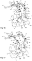
- FIGS. 13 and 14 show steps of attaching the retractor blades of the instrument of FIGS. 1 and 2 to pedicle screws inserted into the pedicles of adjacent vertebrae.
- FIGS. 15 a to 15 d show cross-sectional views of steps of attaching the end portion of a retractor blade of the instrument of FIGS. 1 and 2 to a bone anchoring element, in particular to a pedicle screw, that has been inserted into a pedicle.
- FIG. 16 shows a perspective of a step of attaching the arms and the frame to the retractor blades of the instrument of FIGS. 1 and 2 .
- FIG. 17 shows a perspective view of a step of only retracting tissue with the instrument of FIGS. 1 and 2 .
- FIG. 18 shows a step of attaching the third retractor blade of the instrument of FIGS. 1 and 2 to the frame between the arms, and retracting tissue to allow for better access to the intervertebral space.
- FIG. 19 shows a step of distracting adjacent vertebrae while the retractor blades of the instrument of FIGS. 1 and 2 are fixedly connected to the arms.
- FIG. 20 shows a perspective exploded view of another embodiment of the instrument.
- FIG. 21 shows a perspective view of the instrument of FIG. 20 in an assembled state.
- FIG. 22 shows a detail of FIG. 21 .
- FIG. 23 shows a cross-sectional view of a portion of the instrument of FIGS. 20 and 21 , the cross-section taken in a plane that is perpendicular to a lengthwise extension of a positioning member and that extends through a lengthwise extension of the first arm.
- FIG. 24 shows a cross-sectional view of a portion of the instrument of FIGS. 20 and 21 , the cross-section taken in a plane that is parallel to the lengthwise extension of the positioning member, that is perpendicular to the lengthwise extension of the first arm, and that extends through a center of a connection between a first arm portion and a second arm portion of the first arm.
- FIGS. 25 a to 25 c show different cross-sectional views of the connection between the first arm portion and the second arm portion, in three different pivot positions of the first arm portion relative to the second arm portion, wherein the cross-section is taken in a plane parallel to the positioning member and further away from the positioning member towards a second mounting portion, compared to the cross-section of FIG. 24 .
- an instrument includes a first retractor blade 10 and a second retractor blade 10 ′ that are configured to be connected to bone anchoring elements, for example, bone anchoring elements 100 , 100 ′ as shown in FIGS. 3 and 4 .
- the retractor blades 10 , 10 ′ shown with the instrument each forms an embodiment of an instrument itself for attaching to a bone anchor, according to aspects of the invention.
- Each bone anchoring element 100 , 100 ′ includes a shank 101 that is configured to be anchored in bone, for example in the pedicle of a vertebra, and which may be threaded, and a head 102 that has preferably a spherically-shaped outer surface portion.
- the first retractor blade 10 and the second retractor blade 10 ′ are connectable to a first arm 30 and a second arm 30 ′, respectively, which are attached to a frame that may be a positioning rod 50 , that permits positioning of the first and second arms 30 , 30 ′ relative to each other.
- the second arm 30 ′ is fixedly mounted with a first mounting portion 31 to an end of the positioning rod 50 .
- the first arm 30 is slideably mounted with its first mounting portion 31 on the positioning rod.
- a displacement mechanism 60 is provided for displacing the first arm 30 along the positioning rod 50 .
- second mounting portions 32 are provided for connecting the first and the second retractor blades 10 , 10 ′ to the first and the second arms 30 , 30 ′, respectively.
- a third retractor blade 80 can be mounted to the positioning rod 50 , for example, between the first arm 30 and the second arm 30 ′.
- the first arm 30 and the second arm 30 ′ extend substantially perpendicularly to the positioning rod 50 , towards or away from the same side of the positioning rod 50 .
- the first retractor blade 10 and the second retractor blade 10 ′ respectively extend away from the first arm 30 and the second arm 30 ′ towards the same side or direction, and form an angle of substantially 90°, preferably 90°, with a plane spanned by the positioning rod 50 and the arms 30 , 30 ′ when they are in a straight configuration.
- the first and second retractor blades 10 , 10 ′ are identical. The retractor blades will be described with additional reference to FIGS. 5 to 10 , referring only to the first retractor blade 10 .
- the first retractor blade 10 includes an elongate portion in the form of a blade portion 1 that has a substantially elongate rectangular contour with a rear side 2 and a front side 3 opposite to the rear side 2 .
- the rear side 2 may be flat or slightly convex and the front side 3 may be flat or slightly concave. If the rear side 2 and the front side 3 are convex or concave, respectively, a smooth retraction of soft tissue may be possible with reduced risk of injuring the tissue.
- the blade portion 1 includes an upper end 1 a that is directed towards the arm 30 and an opposite lower end 1 b .
- an attachment portion 4 extends substantially perpendicularly to a longitudinal direction of the elongate blade portion 1 .
- the attachment portion 4 may have a circular segment-shaped outer contour.
- a post 5 extends away from the upper end 1 a of the blade portion 1 .
- the post 5 may have a threaded portion 6 that may be provided at a distance from the free end 5 a of the post 5 .
- the threaded portion 6 serves for cooperating with a fixation nut described below.
- a substantially cylindrical section 7 is provided that serves for pivotably coupling the first and second retractor blades 10 , 10 ′ to the first and second arms 30 , 30 ′, respectively.
- the cylinder axis C of the cylindrical section 7 extends perpendicular to the thread axis T of the threaded portion 6 .
- the cylindrical section 7 is oriented relative to the blade portion 2 in such a manner that a transverse axis t going through the center of the cylindrical section 7 and being perpendicular to the cylinder axis C extends substantially perpendicularly to the long side of the blade portion 1 .
- a spring element or portion such as a leaf spring 8 , may be mounted to the rear side 2 of the blade portion 1 close to the lower end 1 b .
- the spring portion 8 may be arranged substantially at the center of the short side of the elongate blade portion 1 .
- the spring portion 8 includes an upper first end 8 a and a lower second end 8 b , and is curved between the upper end 8 a and the lower end 8 b .
- the spring portion 8 may be attached to the blade portion 2 , for example, with a screw 9 engaging a threaded hole 11 in the rear side 2 .
- the lower end 8 b of the spring portion 8 is free and extends beyond the lower end 1 b of the blade portion 1 and away from the rear side.
- the threaded hole 11 may be provided in an elongate recess 12 that accommodates and guides an upper portion of the spring portion 8 .
- An end portion 13 of the retractor blades 10 , 10 ′ serves to connect the retractor blades 10 , 10 ′ to the heads 102 of the bone anchoring elements 100 , 100 ′, respectively.
- the end portion 13 is configured to accommodate at least a portion of the head 102 of the bone anchoring element 100 , 100 ′.
- the end portion 13 includes an upper face 13 a and a lower end 13 b , and a substantially sleeve-shaped portion 14 adjacent to the lower end 13 b .
- the sleeve-shaped portion 14 includes a first section 14 a and a second section 14 b .
- the second section 14 b includes a surface that forms a seat 15 for pivotably holding the head 102 .
- the surface forming the seat 15 may be spherical-segment-shaped, tapering towards the lower end 13 b , so that when the head 102 is inserted, it is prevented from being removed from the second section 14 b through the lower end 13 b .
- the surface forming the seat 15 may have any other shape that allows pivoting of the head 102 , for example a conical shape.
- a middle axis or seat axis I of the seat may be substantially parallel to the thread axis T when the end portion 13 is mounted to the blade portion 1 .
- the first section 14 a is arranged laterally from the second section 14 b in relation to the seat axis I.
- a lower opening 16 includes a first portion 16 a associated with the first section 14 a and a second portion 16 b associated with the second section 14 b .
- a minimum inner width da at the first portion 16 a of the opening 16 is greater than a maximum outer width E of the head 102 .
- a minimum inner width db at the second portion 16 b of the opening 16 which can form a bottom of the seat 15 , is smaller than the maximum outer width E of the head 102 .
- the portions 16 a and 16 b of the opening 16 each forms a segment of a circle, wherein the radius of the first portion 16 a is greater than the radius of the second portion 16 b.
- the first section 14 a and the second section 14 b may each have conically widening portions 17 a , 17 b , respectively adjacent to the lower end 13 b for facilitating insertion and pivoting of the bone anchoring element 100 , 100 ′.
- Adjacent to the upper face 13 a there is an attachment portion 18 that may have a shape that is adapted to a lower end 1 b of the blade portion 1 .
- the blade portion 1 may be thickened adjacent to its lower end 1 b to a shape that substantially corresponds to the shape of the attachment portion 18 .
- the attachment portion 18 may have a substantially rectangular contour 18 b in a first section that is oriented towards the second section 14 b , and may have a circular segment-shaped section 18 a that is oriented towards the first section 14 a .
- a lower side 18 c of the attachment portion 18 that is directed towards the sleeve-shaped portion 14 may be upwardly inclined and widened.
- a post 19 that may have an oval cross section is provided for connecting the end portion 18 to the lower end 1 b of the blade portion, which includes a corresponding oval-shaped hole.
- the connection may be a press-fit connection.
- a curved recess 20 is provided in the first section 14 a of the sleeve-shaped portion 14 , which starts from the attachment portion 18 and extends steeply towards the lower end 13 b and continues less steeply until it reaches an outer end of the first section 14 a .
- an inserted head 102 is permitted to extend out of the first section 14 a , as can be seen, for example, in FIG. 15 c .
- a second recess 21 may be provided in the second section 14 b . Recess 21 is slightly slanted between the attachment portion 18 and the lower end 13 b .
- Recess 21 may allow the head 102 to extend at least partially therethrough when the head 102 pivots in the seat 15 . Furthermore, between the first section 14 a and the second section 14 b at a distance from the lower end 13 b , a longitudinally extending recess 22 is provided at the inner wall of the sleeve-shaped section 14 between the first section 14 a and the second section 14 b that provides space for moving the head 102 of the bone anchoring element 100 , 100 ′ from the first section 14 a laterally into the second section 14 b .
- the longitudinal recess 22 may end at a distance from the lower end 13 b and at a distance from the smallest width of the seat 15 .
- a lower surface of the attachment portion 18 forms an abutment 23 for an inserted head 102 , limiting upward movement of the head 102 in the direction of or parallel to the seat axis I.
- the end portion 13 is connected to the blade portion 1 in such an orientation that the first section 14 a is facing towards the spring portion 8 .
- the spring portion 8 extends into the first recess 20 .
- the spring portion 8 extends to a distance from an upper edge 24 of the first section 14 a , as shown in FIG. 15 a , for example.
- a plurality of retractor blades 10 may be provided that can be used interchangeably with the instrument and that differ in terms of the length of their respective blade portions 1 , 1 ′, 1 ′′.
- the second mounting portion 32 of the first arm 30 includes an elongate through hole 33 , an inner contour of which corresponds substantially to the outer contour of the cylindrical section 7 of the retractor blade 10 in such a manner that the cylindrical section 7 can be guided into the through hole 33 and accommodated therein.
- the through hole 33 is elongate, pivoting of the cylindrical section 7 in the through hole 33 is limited to pivoting in a single plane that is defined by the thread axis T and the transverse axis t shown in FIG. 5 .
- the orientation of the long sides of the elongate through hole 33 with respect to the longitudinal axis a of the first arm 30 when the first arm 30 is in a straight configuration is in the example shown about 45° inclined towards the second arm 30 ′.
- the blade portion 1 of the first retractor blade is oriented at an angle of approximately 45° outward and away from the second arm 30 ′.
- the second mounting portion 32 of the second arm 30 ′ includes in a similar manner an elongate through hole 33 ′, the orientation of which is, however, mirror symmetrical to the orientation of the elongate through hole 33 , so that the planes extending through the centers and parallel to the long sides of the elongate through holes 33 , 33 ′ form a predefined angle, for example an angle of approximately 90°, preferably 90°.
- the blade portions 1 of the first retractor blade 10 and the second retractor blade 10 ′ from a predefined angle ⁇ , for example, an angle of approximately 90°, which is open towards the positioning rod 50 as depicted in FIG. 1 .
- ⁇ for example, an angle of approximately 90°
- the orientation of the through holes may be such that an angle greater or smaller than 90° between the blade portions 1 of the first retractor blade 10 and the second retractor blade 10 ′ may be achieved.
- each through hole 33 , 33 ′ from an upper side of the second mounting portion 32 to a lower side may be such that the threaded portion 6 of the post 5 extends out of the mounting portion 32 , as depicted in FIG. 16 .
- An outer surface of the mounting portion 32 may be spherically shaped.
- An upper surface 4 a of the attachment portion 4 around the post 5 may have a corresponding spherical shape to form an abutment for the second mounting portion 32 .
- a nut 34 is provided that can be screwed onto the threaded portion 6 of the post 5 to press the mounting portion 32 against the attachment portion 4 , thereby locking the cylindrical section 7 in the through hole 33 , 33 ′ (see also FIG. 11 ).
- the nut 34 may be a cover nut that may have a spherical underside 34 a that slides on the spherical outer surface of the mounting portion 32 .
- Each of the first and second arms 30 , 30 ′ includes a first arm portion 35 adjacent to the second mounting portion 32 and a second arm portion 36 adjacent to the first mounting portion 31 that is attached to the positioning rod 50 .
- the first arm portion 35 and the second arm portion 36 are connected to each other via a hinge 37 , for example, a screw extending through an eyelets as shown in FIGS. 2 and 11 , that provides a pivot axis perpendicular to the arm axis a defined by the first arm portion 35 .
- the extension portion 39 abuts along its length against an upper surface of the second arm portion 36 .
- This straight configuration can be fixed by screwing the connection screw 42 fully into the threaded hole 41 until it abuts against an upper side of the extension portion 39 .
- the connection screw 42 is only partially screwed into the threaded hole 41 so that there is play to allow for a pivoting motion of the second arm portion 36 relative to the first arm portion 35 .
- the second arm portion 36 can be pivoted downward.
- the angled configuration is not fixable. Thereby, it is possible, that an optimum angle can be achieved. This means that during surgery, the positioning rod 50 and the second arm portions 36 can be positioned closer to a patient's body surface.
- the first mounting portion 31 of the first arm 30 includes a passage 43 that extends substantially perpendicularly to the arm axis a when the arm 30 is in a straight configuration.
- the passage 43 is configured to slidably receive the positioning rod 50 therein.
- the passage 43 has a cross section, for example, a rectangular cross section, that allows receipt of the positioning rod in a form-fit manner to prevent rotation of the arm 30 around the positioning rod 50 .
- the positioning rod 50 may have a substantially rectangular cross section.
- a ratchet structure 51 is provided on the positioning rod 50 (shown in FIG. 4 and FIG. 11 ) that permits an incremental movement of the first arm 30 relative to the second arm 30 ′ using the displacement mechanism 60 .
- the ratchet structure 51 may include, for example, triangular or rounded teeth or any other structure that permits incremental movement along the rod axis.
- the displacement mechanism 60 includes an engagement member 61 .
- the engagement member 61 has a hook-like front portion 61 a that is configured to engage the ratchet structure 51 .
- the engagement member 61 is hingedly attached to a holding frame 62 , which is connected to the first mounting portion 31 of the first arm 30 and therefore, can slide with the first mounting portion 31 along the positioning rod 50 .
- a spring 63 is provided to urge the engagement member 61 with the engagement portion 61 a into the valleys of the ratchet structure 51 . By means of this, in the resting position of the engagement member 61 , the hook-like portion 61 a engages the ratchet structure 51 .
- a rear portion 61 b of the engagement member 61 opposite to the engagement portion 61 a is configured to be pushed against the spring force, so that the engagement member 61 pivots around the pivot axis 64 that extends through lateral eyelets 65 of the engagement member 61 . Consequently, pushing the engagement member 61 against the spring force of the spring 63 moves the hook-like front portion 61 a out of engagement with the ratchet structure 51 and permits sliding movement of the first arm 30 along the axis of the positioning rod 50 .
- the sliding movement of the first arm 30 along the positioning rod 50 can be effected in two ways.
- a first way the rear portion 61 b of the engagement member 61 is pushed against the spring force by hand through a user.
- the front portion 61 a is consequently out of engagement with the ratchet structure 51 as long as the rear portion 61 b is pushed.
- This allows continuous sliding movement of the first arm 30 .
- a second way an incremental movement in steps corresponding to the distance of the peaks or valleys of the ratchet structure 51 is enabled.
- a rotary mechanism 66 is provided that includes, for example, a gear or other circumferential ratchet structure 67 that cooperates with the ratchet structure 51 on the positioning rod 50 .
- the gear 67 is operatively connected to the engagement member 61 and urges the spring 63 back every incremental rotational step.
- the engagement member 61 a is released from engagement with the ratchet structure 51 every rotational step.
- a handle 68 may be provided for effecting the rotation.
- Third retractor blade 80 includes a blade portion 81 with a front side 82 that faces the front sides 3 of the blade portions 1 of the first retractor blade 10 and the second retractor blade 10 ′ in a mounted state on the positioning rod 50 .
- the front face 82 may be concave.
- the blade portion 81 is elongate and may have a substantially rectangular contour.
- a mounting post 83 is provided at approximately a center of a surface of the upper end 81 a .
- the mounting post 83 is configured to be received in a mounting portion of a third arm 90 , as explained below.
- a transverse pin 84 that is to be received in a groove is provided.
- the mounting post 83 may have a ring shaped projection 85 that may be received in the mounting portion of the third arm 90 and secured there, for example, by a set screw 86 .
- the third arm 90 includes at one end a mounting portion 91 that has through hole 92 for receiving the post 83 of the third blade 80 .
- a groove 93 extends in a direction parallel to the center axis of the mounting post 83 to receive the transverse pin 84 .
- the blade portion 81 can be mounted to the third arm 90 in a correct orientation.
- the third arm 90 further includes an elongate hole 94 that serves for positioning the blade portion 81 relative to the positioning rod 50 at a variable distance in a direction perpendicular to the rod axis.
- the third arm 90 further includes a second mounting portion 95 , as shown in greater detail in FIG. 2 , that includes a through hole 96 to slidably receive therein the positioning rod 50 .
- a threaded hole 97 is provided that receives a clamping screw 98 , a head 98 a of which has a greater outer width than the transverse width of the elongate through hole 94 .
- An end portion 94 a of the elongate through hole is broadened so as to permit passing through of the head 98 a of the clamping screw 98 .
- the third arm 90 is guided relative to the second mounting portion 95 , for example, via guide grooves 97 a .
- the pre-assembled third arm 90 with the mounted retractor blade 80 can be attached to the second mounting portion 95 by guiding the head 98 a of the clamping screw 98 through the enlarged portion 94 a of the elongate hole 94 . Then, the third arm 90 with the blade portion 81 attached thereto can slide with the elongate recess 94 along the clamping screw 98 , in particular, the third arm 90 and the blade portion 81 can be pulled backward, away from the first and second retractor blades 10 , 10 ′, until the blade portion 81 is at a suitable distance from the positioning rod 50 .
- a handle for example, in the form of an upwardly bent hook 99 , may be provided that is attachable to the third arm 90 via a clamping screw 99 a that engages a threaded hole 99 b and extends through a through hole 99 c of the hook portion.
- the blade portion 81 may optionally have a rearward extension (not shown) at the lower end 81 b that extends away from the blade portions 1 of the first and second retractor blades 10 , 10 ′ and that may have a hook-like function for engaging and retracting soft tissue.
- the connection between the retractor blade 80 and the mounting portion 91 allows to quickly and safely attach and detach various blade portions that may differ in size, in particular, in length or other characteristics.
- the parts and portions of the instrument may be made of any material, preferably, however of titanium or stainless steel or any body-compatible metal alloy or plastic material.
- the blade portions 1 and the end portions, as well as the blade portion 81 should be made of body compatible material, such as titanium or other body compatible metals or metal alloys or of body compatible plastics, such as polyether ether ketone (PEEK).
- body compatible material such as titanium or other body compatible metals or metal alloys or of body compatible plastics, such as polyether ether ketone (PEEK).
- FIGS. 13 to 19 Use of the instrument will be described with reference to FIGS. 13 to 19 .
- the pedicle screws 100 , 100 ′ have been inserted into the pedicles of adjacent vertebrae 500 , 500 ′.
- the intervertebral disk 600 is to be removed and replaced by a cage in order to stabilize the spinal motion segment associated with the vertebrae 500 , 500 ′.
- the first retractor blade 10 and the second retractor blade 10 ′ are placed onto the heads 102 of the bone anchoring elements 100 , 100 ′, respectively.
- FIG. 13 the first retractor blade 10 and the second retractor blade 10 ′ are placed onto the heads 102 of the bone anchoring elements 100 , 100 ′, respectively.
- the head enters the first section 14 a of the end portion 13 through the first opening section 16 a and abuts against the inner side of the spring portion 8 ( FIG. 15 b ).
- an increasing force is exerted by the spring portion 8 onto the head 102 that contributes to urging the head 102 into the second section 14 b of the end portion, or, in other words, to moving the end portion 13 laterally relative to the head 102 so that the head comes into the second section 14 b .
- Due to the shape of the recess 22 the head 102 easily moves into the seat 15 with the aid of the spring portion 8 . As shown in FIG.
- the retractor blade 10 is moved outwards relative to the head to fix the retractor blade to the bone.
- the first and second retractor blades 10 , 10 ′ are still rotatable and pivotable around the head 102 as the seat 15 provides a polyaxial connection.
- the positioning rod 50 with the first and the second arms 30 , 30 ′ mounted thereon and optionally the first mounting portion 95 of the third retractor blade 80 mounted between the first and second arms 30 , 30 ′, is attached to the retractor blades 10 , 10 ′.
- the first and second retractor blades 10 , 10 ′ are oriented such that their cylindrical sections 7 can be inserted into the through holes 33 , 33 ′.
- the blade portions 1 of the first and second retractor blades 10 , 10 ′ will also form a corresponding predefined angle, correspondingly 90° for example, with respect to each other.
- the nuts 34 are screwed onto the threaded portions 6 of posts 5 but not yet tightened. Consequently, as shown by the arrows in FIG. 17 , due to the cylindrical sections 7 received in the through holes 33 , 33 ′, the first and second retractor blades 10 , 10 ′ are pivotable in a single plane.
- the first and second retractor blades 10 , 10 ′ can pivot in that single plane and the blade portions 1 can pivot outwards in their V-orientation relative to each other, as indicated by the curved arrows.
- the retractor blades 10 , 10 ′ are also pivotable relative to the heads 102 . Thereby, forces acting onto the bone are minimized or reduced.
- the first and second retractor blades 10 , 10 ′ are used for retraction of tissue.
- the third retractor blade 80 which has been mounted to the arm 90 in an orientation such that its front surface 82 faces towards the blade portions 1 of the first and second retractor blades 10 , 10 ′, is placed on the mounting portion 95 to attach the third retractor blade 80 to the positioning rod 50 .
- the head 98 a of the clamping screw 98 is guided through the enlarged end 94 a of the elongate through hole 94 and moved laterally relative to the elongate through hole 94 so that the arm cannot be removed.
- the handle 99 the third retractor blade 80 is drawn backwards, thereby retracting soft tissue from the surgical site.
- the position of the third retractor blade 80 is fixed by tightening the clamping screw 98 .
- the nuts 34 are tightened to lock the angular position of the first and second retractor blades 10 , 10 ′.
- the arm 30 can be displaced relative to the arm 30 ′ with the displacement mechanism 60 to perform distraction on the vertebrae 500 , 500 ′.
- the retractor blades 10 , 10 ′ can be pivotable relative to the heads 102 . Thereby, forces acting onto the bone can be reduced.
- the third retractor blade 80 has been removed again.
- the third retractor blade can stay on the positioning rod 50 .
- the distance between the first and second arms 30 , 30 ′ is increased, the intervertebral space between the vertebrae 500 , 500 ′ may be enlarged. Thereby, it is possible to remove the intervertebral disk and to insert a cage.
- first and second retractor blades 10 , 10 ′ are removed. Thereafter polyaxial receiving parts may be placed onto the heads 102 of the pedicle screws and a spinal fixation rod may be inserted into the receiving parts and fixed thereto.
- first and second arms 30 , 30 ′ are in the straight configuration. If the situation at the surgical site requires it, the connection screws 42 may be loosened to permit the second arm portions 36 , together with the positioning rod 50 , to assume an angled configuration relative to the first arm portions 35 , as shown, for example, in FIG. 11 .
- FIGS. 20 to 25 c Another embodiment of the instrument will be explained, referring to FIGS. 20 to 25 c .
- the instrument of FIGS. 20 to 25 c differs from the instrument of the embodiment described before in the construction and functionality of the arms. All other parts are identical or very similar to those of the previously described embodiments. Identical or very similar parts and portions are marked with the same reference numerals, and the descriptions thereof will not be repeated.
- the instrument includes a first arm 300 and a second arm 300 ′.
- the first arm 300 is associated with the first mounting portion 31 that is connected to the holding frame 62 ′ of the displacement mechanism 60 .
- the holding frame 62 ′ is very similar to the holding frame 62 of the previous embodiments, but holds the displacement mechanism along opposite sides of the positioning member 50 that are adjacent to and on either side of the ratchet structure 51 .
- the second arm 300 ′ is associated with the first mounting portion 31 that is fixedly connected to the positioning member 50 at an end of the positioning member.
- Each of the first and second arms 300 , 300 ′ includes a first arm portion 350 adjacent to the second mounting portion 320 which receives the blades 10 , 10 ′ and a second arm portion 360 adjacent to the first mounting portion 31 that is attached to the positioning rod 50 .
- the first arm portion 350 and the second arm portion 360 are connected to each other via a connection structure 400 .
- the connection structure 400 is configured to permit a pivoting or rotation of the first arm portion 350 relative to the second arm portion 360 .
- additional degrees of freedom for positioning of the first and second retractor blades 10 , 10 ′ can be realized.
- the connection between the first and second retractor blades for example, does not need to be pivotable.
- the second mounting portion 320 includes a through-hole 330 that extends perpendicular to a longitudinal extension of the first arm portion 350 , and serves for receiving respective portions of the retractor blades 10 , 10 ′ as in the previous embodiments.
- the retractor blades 10 , 10 ′ can be clicked into the second mounting portions 320 , respectively, and held therein in a single angular position.
- the second arm portion 360 includes a passage 410 that is configured to receive a connection pin 420 therethrough.
- the cross-section of the second arm portion 360 is, in a region adjacent the free end 360 a , substantially elongate with opposite circular short edges, obtained, for example, by cutting opposite and parallel flat faces into a cylindrical projection.
- the connection pin 420 includes a head portion 421 and, adjacent thereto, an unthreaded portion 422 with a reduced width, followed by a threaded portion 423 and a tip portion 424 .
- the passage 410 is adapted to receive the head portion 421 and a part of the unthreaded portion 422 of the connection pin 420 .
- FIGS. 23 and 24 which depict views of the cross-section of the connection pin that are rotated by 90° from one another, the head 421 of the connection pin 420 is mirror-symmetrical and not rotatable in the passage 410 .
- the connection between the second arm portion 360 and the pin 420 is a form-fit connection.
- connection structure 400 further includes a connection body 430 that has a substantially cylindrical upper side 431 , with the cylinder axis being perpendicular to the longitudinal axis of the positioning member 50 . Otherwise, the connection body 430 may be substantially cuboid-shaped and may have a slanted front face 432 that faces towards the second mounting portion 320 .
- the connection body 430 includes a cylindrical bore 433 that is open towards the second arm portion 360 and closed at its opposite end, and that serves for receiving the second arm portion 360 partially therein. As best seen in FIGS. 25 a to 25 c , the cylindrical bore 433 has a size such that the connection body 430 can pivot relative to the second arm portion 360 .
- the passage 410 is located in the bore 433 .
- the connection body 430 includes a bottom transverse through-bore 434 that extends from a side of the connection body opposite the cylindrical surface 431 into the bore 433 .
- an opening 435 is formed in the connection body 430 that permits the connection pin 420 to extend therethrough and protrude out of the cylindrical upper surface 431 .
- the opening 435 is mirror-symmetrical but not rotationally symmetrical. In the direction perpendicular to the longitudinal axis of the positioning member 50 , as shown in FIG.
- the opening 435 holds the connection pin 420 so that it cannot pivot relative to the connection body 430 about an axis that is parallel to the longitudinal axis of the positioning member 50 .
- the opening 435 is conically widening towards the cylindrical upper surface 431 , so that the connection body 430 can pivot relative to the second arm portion 360 about an axis that is perpendicular to the longitudinal axis of the positioning member 50 . Since the connection body 430 is a part of the first arm portion 350 , the first arm portion 350 can also pivot relative to the second arm portion 360 about the same axis.
- connection pin 420 has a length such that the unthreaded portion 422 protrudes out of the cylindrical surface 431 when the connection pin 420 is received.
- connection body 430 further includes an engagement structure in the form of a groove structure 436 including a plurality of, in the embodiment shown three, substantially parallel grooves that extend in the lengthwise direction of the first arm portion 350 , formed in the cylindrical surface 431 .
- Corresponding parallel indication grooves 437 may be provided in the inclined surface 432 which may assist a user in adjusting the first arm portions 350 to a desired pivot position.
- the connection structure 400 further includes an adjustment member 440 and a fixation member 450 .
- a corresponding engagement structure at the adjustment member 440 provides an engagement between the connection body 430 and the adjustment member 440 configured to permit adjustment to various engagement positions.
- the adjustment member 440 includes a cylindrical lower surface 441 matching the cylindrical surface 431 of the connection body 430 , with an engagement structure in the form of a projection or rib and groove structure 442 extending parallel to the cylinder axis and having a central projection 442 a .
- the projection and groove structure 442 is configured to cooperate with the groove structure 436 to adjust a pivot position of the connection body 430 relative to the second arm portion 360 .
- the central projection 442 a can assume three positions.
- a zero position is defined when the central projection 442 a engages the central groove ( FIG. 25 b ).
- the first arm portion 350 and the second arm portion 360 are aligned in such a manner that the central bore 330 of the second mounting portion 320 is perpendicular to the longitudinal axis of the positioning member 50 .
- Second and third pivot positions are defined by the central projection 442 a engaging the grooves to the right and to the left of the central groove, respectively, of the groove structure, so that the first arm portion 350 is pivoted in one direction or the other direction, respectively.
- the pivot angle may be around ⁇ 5°.
- the bore axis of the retractor blade receiving bore 330 of the second mounting portion 320 is also pivoted.
- the adjustment member 440 further includes, opposite to the cylindrical surface 441 , a substantially tubular connection portion 443 with a collar 443 a , wherein the tubular connection portion 443 is receivable in the fixation member 450 and rotatable relative thereto.
- the fixation member 450 is a nut member including a lower part 451 that is configured to cooperate with and press onto an outer slanted surface 444 of the adjustment member 440 , and an upper part 452 that is configured to cooperate with the threaded portion 423 of the connection pin 420 .
- connection pin 420 when the connection pin 420 extends through a first arm portion 350 and a second arm portion 360 and protrudes out of the connection body 430 , the adjustment member 440 engages the cylindrical surface 431 , and the fixation member 450 rotatably holds the adjustment member 440 and engages the threaded portion 423 of the connection pin 420 .
- the connection pin 420 preferably has a length such that it may protrude out of the fixation member 450 .
- connection body 430 can pivot relative to the adjustment member 440 as depicted in FIGS. 25 a and 25 c .
- the cylindrical surfaces of the connection body 430 and of the adjustment member 440 slide along each other, until the central projection 442 a snaps into one of the grooves of the groove structure 436 .
- the respective pivot position is fixed by tightening the fixation member 450 , which presses onto the slanted surface 444 of the adjustment member 440 , which in turn firmly engages the central projection 442 a with one of the grooves of the groove structure 436 .
- the pivot position is fixed.
- the above described embodiments have robust structures and are easy to operate. Various positions of the retractor blades can be adjusted.
- the engagement structures can also further be designed to provide more refined positions.
- the retractor blades can be adjusted independently from each other.
- the shape of the blade portions or of the retractor blades as a whole may be different.
- the spring force may be generated by a spring other than a leaf spring.
- the displacement mechanism may be constructed in a different manner.
- the third retractor blade may be omitted.
- the frame can be shaped other than in the form of a positioning rod. Any shape that allows a displacement of the first arm 30 relative to the second arm 30 ′ may be conceivable.
- the instrument may also be used for performing other surgical steps in the procedure, for example for compressing vertebrae or bone parts towards each other.
- the retractor blades may be mounted, for example, to the arms in a 180° rotated configuration.
Abstract
Description
Claims (17)
Priority Applications (1)
| Application Number | Priority Date | Filing Date | Title |
|---|---|---|---|
| US16/577,961 US11219477B2 (en) | 2018-09-21 | 2019-09-20 | Instrument for attaching to a bone anchor and instrument for use in distraction and/or retraction, in particular for orthopedic surgery or neurosurgery, more specifically for spinal surgery |
Applications Claiming Priority (5)
| Application Number | Priority Date | Filing Date | Title |
|---|---|---|---|
| US201862734485P | 2018-09-21 | 2018-09-21 | |
| EP18196118 | 2018-09-21 | ||
| EP18196118.6 | 2018-09-21 | ||
| EP18196118.6A EP3626189B1 (en) | 2018-09-21 | 2018-09-21 | Instrument for attaching to a bone anchor and instrument for use in distraction and/or retraction, in particular for orthopedic or neurosurgery, more specifically for spinal surgery |
| US16/577,961 US11219477B2 (en) | 2018-09-21 | 2019-09-20 | Instrument for attaching to a bone anchor and instrument for use in distraction and/or retraction, in particular for orthopedic surgery or neurosurgery, more specifically for spinal surgery |
Publications (2)
| Publication Number | Publication Date |
|---|---|
| US20200093529A1 US20200093529A1 (en) | 2020-03-26 |
| US11219477B2 true US11219477B2 (en) | 2022-01-11 |
Family
ID=63678558
Family Applications (1)
| Application Number | Title | Priority Date | Filing Date |
|---|---|---|---|
| US16/577,961 Active 2040-02-20 US11219477B2 (en) | 2018-09-21 | 2019-09-20 | Instrument for attaching to a bone anchor and instrument for use in distraction and/or retraction, in particular for orthopedic surgery or neurosurgery, more specifically for spinal surgery |
Country Status (2)
| Country | Link |
|---|---|
| US (1) | US11219477B2 (en) |
| EP (1) | EP3626189B1 (en) |
Families Citing this family (4)
| Publication number | Priority date | Publication date | Assignee | Title |
|---|---|---|---|---|
| CN111671554B (en) * | 2020-05-26 | 2020-12-22 | 常州集硕医疗器械有限公司 | Cervical vertebra minimally invasive expansion type intervertebral fusion system |
| US11350922B1 (en) | 2021-02-03 | 2022-06-07 | Warsaw Orthopedic, Inc. | Modular surgical instrument system and method for shank-based retraction and distraction |
| US11432852B1 (en) | 2021-03-22 | 2022-09-06 | Warsaw Orthopedic, Inc. | Screw shank based tissue retraction |
| US20230240671A1 (en) * | 2022-01-31 | 2023-08-03 | Nuvasive, Inc. | Surgical retraction system |
Citations (8)
| Publication number | Priority date | Publication date | Assignee | Title |
|---|---|---|---|---|
| US8636655B1 (en) | 2010-01-19 | 2014-01-28 | Ronald Childs | Tissue retraction system and related methods |
| WO2015137976A1 (en) | 2014-03-14 | 2015-09-17 | Wright Medical Technology, Inc. | Orthopedic compression/distraction device |
| US9307972B2 (en) * | 2011-05-10 | 2016-04-12 | Nuvasive, Inc. | Method and apparatus for performing spinal fusion surgery |
| US20160106408A1 (en) | 2014-10-21 | 2016-04-21 | Globus Medical, Inc. | Orthopedic Tools for Implantation |
| EP3023065A1 (en) | 2014-11-24 | 2016-05-25 | Aesculap Ag | Pedicle screw system and spinal column-stabilizing system |
| US9414828B2 (en) * | 2014-05-01 | 2016-08-16 | Blackstone Medical, Inc. | Integrated retractor-distractor system for use with modular bone screws |
| US20170143323A1 (en) | 2015-08-18 | 2017-05-25 | Globus Medical, Inc. | Devices and systems for surgical retraction |
| DE102016110706A1 (en) | 2016-06-10 | 2017-12-14 | Fehling Instruments Gmbh & Co. Kg | Spreader for spine surgery |
Family Cites Families (2)
| Publication number | Priority date | Publication date | Assignee | Title |
|---|---|---|---|---|
| EP2764840B1 (en) | 2013-02-11 | 2017-05-03 | Biedermann Technologies GmbH & Co. KG | Coupling assembly for coupling a rod to a bone anchoring element and bone anchoring device with such a coupling assembly |
| EP3278750B1 (en) | 2016-08-04 | 2018-12-12 | Biedermann Technologies GmbH & Co. KG | Polyaxial bone anchoring device and system of an instrument and a polyaxial bone anchoring device |
-
2018
- 2018-09-21 EP EP18196118.6A patent/EP3626189B1/en active Active
-
2019
- 2019-09-20 US US16/577,961 patent/US11219477B2/en active Active
Patent Citations (9)
| Publication number | Priority date | Publication date | Assignee | Title |
|---|---|---|---|---|
| US8636655B1 (en) | 2010-01-19 | 2014-01-28 | Ronald Childs | Tissue retraction system and related methods |
| US9307972B2 (en) * | 2011-05-10 | 2016-04-12 | Nuvasive, Inc. | Method and apparatus for performing spinal fusion surgery |
| WO2015137976A1 (en) | 2014-03-14 | 2015-09-17 | Wright Medical Technology, Inc. | Orthopedic compression/distraction device |
| EP2934354A1 (en) | 2014-03-14 | 2015-10-28 | Wright Medical Technology, Inc. | Orthopedic compression/distraction device |
| US9414828B2 (en) * | 2014-05-01 | 2016-08-16 | Blackstone Medical, Inc. | Integrated retractor-distractor system for use with modular bone screws |
| US20160106408A1 (en) | 2014-10-21 | 2016-04-21 | Globus Medical, Inc. | Orthopedic Tools for Implantation |
| EP3023065A1 (en) | 2014-11-24 | 2016-05-25 | Aesculap Ag | Pedicle screw system and spinal column-stabilizing system |
| US20170143323A1 (en) | 2015-08-18 | 2017-05-25 | Globus Medical, Inc. | Devices and systems for surgical retraction |
| DE102016110706A1 (en) | 2016-06-10 | 2017-12-14 | Fehling Instruments Gmbh & Co. Kg | Spreader for spine surgery |
Non-Patent Citations (1)
| Title |
|---|
| Extended European Search Report for Application No. 18196118.6, dated Mar. 14, 2019, 9 pages. |
Also Published As
| Publication number | Publication date |
|---|---|
| EP3626189B1 (en) | 2023-05-24 |
| EP3626189A1 (en) | 2020-03-25 |
| US20200093529A1 (en) | 2020-03-26 |
Similar Documents
| Publication | Publication Date | Title |
|---|---|---|
| US11219477B2 (en) | Instrument for attaching to a bone anchor and instrument for use in distraction and/or retraction, in particular for orthopedic surgery or neurosurgery, more specifically for spinal surgery | |
| US11849978B2 (en) | Constrained motion bone screw assembly | |
| USRE49410E1 (en) | Rod reducer, compressor, distractor system | |
| US8100828B2 (en) | Distraction and retraction system for spinal surgery | |
| US9820779B2 (en) | Spinal stabilization system | |
| EP2713915B1 (en) | Minimally invasive spinal fixation system including vertebral alignment features | |
| EP2467076B1 (en) | Transverse rod connector | |
| US20070208228A1 (en) | Surgical retractors and methods of minimally invasive surgery | |
| US20080021285A1 (en) | Surgical retractor for use with minimally invasive spinal stabilization systems and methods of minimally invasive surgery | |
| US9138264B2 (en) | Laminoplasty rod system | |
| US10973552B2 (en) | Surgical system for bone screw insertion and rod reduction | |
| US20220133364A1 (en) | Polyaxial Bone Screw With Increased Angulation | |
| US11737791B2 (en) | System and instrument for correcting a position of bones, bone parts, or vertebrae | |
| EP3900656A1 (en) | Single level fusion systems | |
| EP3482703A1 (en) | Distraction and compression assembly, in particular for bone surgery | |
| US11931081B2 (en) | Monoaxial-uniplanar hybrid screw | |
| US20210290274A1 (en) | Spinal Implant And Methods Of Use Thereof |
Legal Events
| Date | Code | Title | Description |
|---|---|---|---|
| FEPP | Fee payment procedure |
Free format text: ENTITY STATUS SET TO UNDISCOUNTED (ORIGINAL EVENT CODE: BIG.); ENTITY STATUS OF PATENT OWNER: LARGE ENTITY |
|
| AS | Assignment |
Owner name: BIEDERMANN MOTECH GMBH & CO. KG, GERMANY Free format text: ASSIGNMENT OF ASSIGNORS INTEREST;ASSIGNORS:BIEDERMANN, TIMO;DANDANOPOULOS, DIMOSTHENIS;REEL/FRAME:050982/0391 Effective date: 20191029 |
|
| AS | Assignment |
Owner name: BIEDERMANN TECHNOLOGIES GMBH & CO. KG, GERMANY Free format text: ASSIGNMENT OF ASSIGNORS INTEREST;ASSIGNOR:BIEDERMANN MOTECH GMBH & CO. KG;REEL/FRAME:051359/0105 Effective date: 20191125 |
|
| STPP | Information on status: patent application and granting procedure in general |
Free format text: NON FINAL ACTION MAILED |
|
| STPP | Information on status: patent application and granting procedure in general |
Free format text: RESPONSE TO NON-FINAL OFFICE ACTION ENTERED AND FORWARDED TO EXAMINER |
|
| STPP | Information on status: patent application and granting procedure in general |
Free format text: NOTICE OF ALLOWANCE MAILED -- APPLICATION RECEIVED IN OFFICE OF PUBLICATIONS |
|
| STPP | Information on status: patent application and granting procedure in general |
Free format text: AWAITING TC RESP., ISSUE FEE NOT PAID |
|
| STPP | Information on status: patent application and granting procedure in general |
Free format text: PUBLICATIONS -- ISSUE FEE PAYMENT RECEIVED |
|
| STPP | Information on status: patent application and granting procedure in general |
Free format text: PUBLICATIONS -- ISSUE FEE PAYMENT VERIFIED |
|
| STCF | Information on status: patent grant |
Free format text: PATENTED CASE |