US11217841B2 - System and method for thermally managing battery - Google Patents
System and method for thermally managing battery Download PDFInfo
- Publication number
- US11217841B2 US11217841B2 US16/422,362 US201916422362A US11217841B2 US 11217841 B2 US11217841 B2 US 11217841B2 US 201916422362 A US201916422362 A US 201916422362A US 11217841 B2 US11217841 B2 US 11217841B2
- Authority
- US
- United States
- Prior art keywords
- coolant
- battery
- heat exchange
- heat
- temperature
- Prior art date
- Legal status (The legal status is an assumption and is not a legal conclusion. Google has not performed a legal analysis and makes no representation as to the accuracy of the status listed.)
- Active, expires
Links
Images

Classifications
-
- H—ELECTRICITY
- H01—ELECTRIC ELEMENTS
- H01M—PROCESSES OR MEANS, e.g. BATTERIES, FOR THE DIRECT CONVERSION OF CHEMICAL ENERGY INTO ELECTRICAL ENERGY
- H01M10/00—Secondary cells; Manufacture thereof
- H01M10/60—Heating or cooling; Temperature control
- H01M10/65—Means for temperature control structurally associated with the cells
- H01M10/657—Means for temperature control structurally associated with the cells by electric or electromagnetic means
- H01M10/6572—Peltier elements or thermoelectric devices
-
- H—ELECTRICITY
- H01—ELECTRIC ELEMENTS
- H01M—PROCESSES OR MEANS, e.g. BATTERIES, FOR THE DIRECT CONVERSION OF CHEMICAL ENERGY INTO ELECTRICAL ENERGY
- H01M10/00—Secondary cells; Manufacture thereof
- H01M10/60—Heating or cooling; Temperature control
- H01M10/61—Types of temperature control
- H01M10/617—Types of temperature control for achieving uniformity or desired distribution of temperature
-
- H—ELECTRICITY
- H01—ELECTRIC ELEMENTS
- H01M—PROCESSES OR MEANS, e.g. BATTERIES, FOR THE DIRECT CONVERSION OF CHEMICAL ENERGY INTO ELECTRICAL ENERGY
- H01M10/00—Secondary cells; Manufacture thereof
- H01M10/60—Heating or cooling; Temperature control
- H01M10/62—Heating or cooling; Temperature control specially adapted for specific applications
- H01M10/625—Vehicles
-
- H—ELECTRICITY
- H01—ELECTRIC ELEMENTS
- H01M—PROCESSES OR MEANS, e.g. BATTERIES, FOR THE DIRECT CONVERSION OF CHEMICAL ENERGY INTO ELECTRICAL ENERGY
- H01M10/00—Secondary cells; Manufacture thereof
- H01M10/60—Heating or cooling; Temperature control
- H01M10/65—Means for temperature control structurally associated with the cells
- H01M10/656—Means for temperature control structurally associated with the cells characterised by the type of heat-exchange fluid
- H01M10/6561—Gases
- H01M10/6563—Gases with forced flow, e.g. by blowers
-
- H—ELECTRICITY
- H01—ELECTRIC ELEMENTS
- H01M—PROCESSES OR MEANS, e.g. BATTERIES, FOR THE DIRECT CONVERSION OF CHEMICAL ENERGY INTO ELECTRICAL ENERGY
- H01M2220/00—Batteries for particular applications
- H01M2220/20—Batteries in motive systems, e.g. vehicle, ship, plane
-
- Y—GENERAL TAGGING OF NEW TECHNOLOGICAL DEVELOPMENTS; GENERAL TAGGING OF CROSS-SECTIONAL TECHNOLOGIES SPANNING OVER SEVERAL SECTIONS OF THE IPC; TECHNICAL SUBJECTS COVERED BY FORMER USPC CROSS-REFERENCE ART COLLECTIONS [XRACs] AND DIGESTS
- Y02—TECHNOLOGIES OR APPLICATIONS FOR MITIGATION OR ADAPTATION AGAINST CLIMATE CHANGE
- Y02E—REDUCTION OF GREENHOUSE GAS [GHG] EMISSIONS, RELATED TO ENERGY GENERATION, TRANSMISSION OR DISTRIBUTION
- Y02E60/00—Enabling technologies; Technologies with a potential or indirect contribution to GHG emissions mitigation
- Y02E60/10—Energy storage using batteries
Definitions
- the present disclosure relates to a system and method for thermally managing a battery.
- Lithium batteries applied to hybrid electric vehicles (HEVs), plug-in hybrid electric vehicles (PHEVs), and electric vehicles (EVs) are advantageous in terms of output and energy density, compared with existing nickel-metal hydride (Ni-MH) batteries.
- Thermal management of a battery is important to prevent a degradation of a lifespan and an output.
- an air cooling-type cooling system for forcibly blowing air toward a battery by means of a cooling fan or a water cooling-type cooling system using water or oil is used.
- a battery heating system for heating a battery using a heater core, a surface type heater is applied.
- the water cooling-type cooling system has a very complicated structure for excellent cooling performance.
- the existing water cooling-type cooling system is associated with a vehicle air-conditioning system, resulting in a very complicated overall structure, and thus, it is required to check an overall layout and performance of the existing water cooling-type cooling system in respect to a vehicle air-conditioning system when designed.
- the present disclosure provides a system and method for thermally managing a battery capable of simplifying an overall layout by unifying a cooling system and a heating system without the necessity of associating with a vehicle air-conditioning system, and considerably improving cooling and heating efficiency of a battery by effectively cooling or heating a coolant heat-exchanged with a battery using the Peltier effect of a thermoelectric element.
- a system for thermally managing a battery includes: a thermal manager performing a thermal management of a battery by means of a coolant; a coolant circulation line being connected to the thermal manager; and a heat exchanger being installed to the coolant circulation line.
- the heat exchanger may include: a heat exchange member being installed to the coolant circulation line to cool or heat the coolant; a thermoelectric element being attached to the heat exchange member; and a heat sink being attached to the thermoelectric element.
- thermoelectric elements may be symmetrically attached to the heat exchange member and a pair of heat sinks may be attached to the thermoelectric elements such that the pair of heat sinks may be symmetrically disposed with respect to the heat exchange member.
- thermoelectric element may have a first surface in contact with the heat exchange member and a second surface in contact with the heat sink, and a polarity change switch changing polarity may be connected to the thermoelectric element.
- the system may further include: a first temperature sensor being installed to the battery to detect a temperature of the battery, and a second temperature sensor being installed to the coolant circulation line to detect a temperature of the coolant.
- the system may further include: a cooling fan being disposed to face the heat sink.
- the heat exchange member may include a plurality of heat exchange plates being spaced apart from one another at a predetermined interval, and a heat exchange tube penetrating through the plurality of heat exchange plates, and the coolant moves through the heat exchange tube.
- the heat exchange tube may be a straight tube.
- a plurality of inner fins are formed on an inner surface of the heat exchange tube.
- the heat exchange member may include a serpentine heat exchange tube being connected to the coolant circulation line and a heat exchange block covering an outer surface of the serpentine heat exchange tube.
- the heat exchange member may include a heat exchange duct being connected to the coolant circulation line, and a grid frame in which a plurality of grid flow channels are formed at a uniform interval may be installed inside the heat exchange duct.
- the heat exchange duct may have an inlet, through which a coolant is introduced, and an outlet, through which the coolant is discharged, formed at both end portions thereof, and may have a structure bent to have a U shape.
- the inlet and the outlet of the heat exchange duct may have a cross-sectional area smaller than that of the heat exchange duct, and the inlet and the outlet may be connected to one end and the other end of the heat exchange duct by the medium of expansion type connection portions.
- a baffle having a plurality of small through holes may be installed within the expansion type connection portions.
- a system for thermally managing a battery includes: a thermal manager allowing a coolant to flow therein to cool or heat a battery and having an inlet through which the coolant is introduced and an outlet through which the coolant is discharged; a coolant circulation line connecting the inlet and the outlet of the thermal manager; a coolant circulation pump pumping the coolant to the thermal manager; and a heat exchanger having a thermoelectric element being installed to the coolant circulation line to cool or heat the coolant by changing polarity.
- the battery may be a battery installed in any one of a hybrid electric vehicle (HEV), a plug-in hybrid electric vehicle (PHEV), a fuel cell electric vehicle (FCEV), and an electric vehicle (EV).
- HEV hybrid electric vehicle
- PHEV plug-in hybrid electric vehicle
- FCEV fuel cell electric vehicle
- EV electric vehicle
- a method of thermally managing a battery including a thermal manager having a coolant which exchanges heat with a battery and flows in the thermal manager, a coolant circulation line being connected to the thermal manager, and a heat exchanger being installed to the coolant circulation line, having a thermoelectric element, and cooling or heating the coolant by changing polarity, comprises measuring a temperature of the battery; performing selectively a cooling operation of the thermoelectric element to cool the coolant when the measured temperature of the battery exceeds an upper limit threshold value of the battery; and performing selectively a heating operation of the thermoelectric element to heat the coolant when the measured temperature of the battery is lower than a lower limit threshold value of the battery.
- a temperature of the battery and a temperature of the coolant may be measured, and when the measured temperature of the battery exceeds the upper limit threshold value of the battery and the measured temperature of the coolant is lower than that of the battery, the coolant may be cooled by a cooling operation of the thermoelectric element and the coolant may be pumped to the thermal manager.
- a temperature of the battery and a temperature of the coolant may be measured, and when the measured temperature of the battery exceeds the upper limit threshold value of the battery and the measured temperature of the coolant is higher than that of the battery, pumping the coolant to the thermal manager may be interrupted and the coolant may be cooled by a cooling operation of the thermoelectric element.
- a temperature of the battery and a temperature of the coolant may be measured, and when the measured temperature of the battery is lower than a lower limit threshold value of the battery and the measured temperature of the coolant is higher than that of the battery, the coolant may be heated by a heating operation of the thermoelectric element and the coolant may be pumped to the thermal manager.
- a temperature of the battery and a temperature of the coolant may be measured, and when the measured temperature of the battery is lower than the lower limit threshold value of the battery and the measured temperature of the coolant is lower than that of the battery, pumping the coolant to the thermal manager may be interrupted and the coolant may be heated by a heating operation of the thermoelectric element.
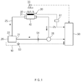
- FIG. 1 is a view illustrating a configuration of a system for thermally managing a battery according to an exemplary form of the present disclosure
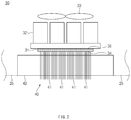
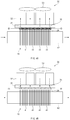
- FIG. 2 is a side view illustrating a heat exchanger according to a first form applied to a system for thermally managing a battery of the present disclosure
- FIG. 3 is a perspective view illustrating a heat exchanger (without a cooling pan) according to a first exemplary form of the present disclosure of FIG. 2 ;
- FIGS. 4A and 4B are views illustrating a state in which a thermoelectric element of a heat exchanger cools or heats a coolant by converting polarity according to the first exemplary form of the present disclosure of FIG. 2 , wherein FIG. 4A is a view illustrating a state in which a coolant is cooled by the thermoelectric element and FIG. 4B is a view illustrating a state in which a coolant is heated by the thermoelectric element;
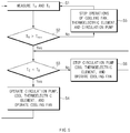
- FIG. 5 is a flow chart illustrating a cooling logic in a method for thermally managing a battery according to an exemplary form of the present disclosure
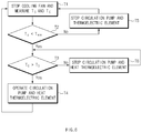
- FIG. 6 is a flow chart illustrating a heating logic in the method for thermally managing a battery according to an exemplary form of the present disclosure
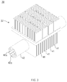
- FIG. 7 is a side view illustrating a heat exchanger according to a second exemplary form of the present disclosure applied to a system for thermally managing a battery of the present disclosure
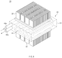
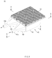
- FIG. 8 is a perspective view illustrating a heat exchanger according to the second exemplary form of FIG. 7 ;
- FIG. 9 is a perspective view illustrating a heat exchanger according to a third exemplary form of the present disclosure applied to a system for thermally managing a battery of the present disclosure
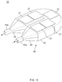
- FIG. 10 is a perspective view illustrating a state in which a heat sink and a cooling pan are removed from the heat exchanger according to the third exemplary form of FIG. 9 ;
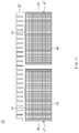
- FIG. 11 is a cross-sectional view taken along line A-A of FIG. 9 ;
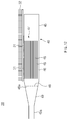
- FIG. 12 is a cross-sectional view taken along line B-B of FIG. 9 .
- FIGS. 1 through 4A and 4B are views illustrating a system for thermally managing a battery according to an exemplary form of the present disclosure.
- a system for thermally managing a battery includes a thermal manager 20 performing thermal management on a battery 10 , a coolant circulation line 25 connected to the thermal manager 20 , and a heat exchanger 30 installed to the coolant circulation line 25 .
- the thermal manager 20 is in contact with a battery 10 and has a coolant flowing circuit (not shown) therein.
- a coolant flowing in the coolant flowing circuit of the thermal manager 20 may exchange heat with the battery 10 to cool or heat the battery 10 , thereby appropriately performing thermal management on the battery 10 .
- the thermal manager 20 in contact with the battery 10 allows the coolant to exchange heat with the battery 10 , thus performing thermal management on the battery 10 .
- the thermal manager 20 may be configured as a thermal jacket having a coolant flowing circuit therein.
- a coolant flowing circuit (not shown) may have a structure such as a serpentine flow path, or the like.
- the battery 10 may be a battery installed in any one of a hybrid electric vehicle (HEV), a plug-in hybrid electric vehicle (PHEV), and a fuel cell electric vehicle (FCEV), and an electric vehicle (EV).
- HEV hybrid electric vehicle
- PHEV plug-in hybrid electric vehicle
- FCEV fuel cell electric vehicle
- EV electric vehicle
- the thermal manager 20 may have an inlet 21 through which a coolant is introduced and an outlet 22 through which the coolant is discharged, and the inlet 21 and the outlet 22 communicate with the coolant flowing circuit (not shown).
- the coolant circulation line 25 connects the inlet 21 and the outlet 22 of the thermal manager 20 , and through the coolant circulation line 25 , a coolant may be introduced through the inlet 21 of the thermal manager 20 , exchange heat with the battery 10 , and subsequently discharged to the outlet 22 of the thermal manager 20 .
- a coolant circulation pump 26 pumping a coolant toward the inlet 21 of the thermal manager 20 is installed to the coolant circulation line 25 .
- the heat exchanger 30 is installed on one side of the coolant circulation line 25 , and particularly, the heat exchanger 30 may be disposed to be adjacent to the outlet 22 of the thermal manager 20 or may be disposed in the middle portion between the outlet 22 and the inlet 21 of the thermal manager 20 .
- the heat exchanger 30 includes a heat exchange member 40 installed to the coolant circulation line 25 , a thermoelectric element 31 attached to the heat exchange member 40 , a heat sink 32 attached to the thermoelectric element 31 , and a cooling fan 33 disposed to face the heat sink 32 .
- the heat exchange member 40 includes a plurality of heat exchanging plates 41 being spaced apart from one another by a predetermined small interval and a heat exchange tube 42 penetrating through the plurality of heat exchanging plates 41 .
- the plurality of heat exchanging plates 41 are disposed to be spaced apart from one another by a predetermined interval in the direction of moving a coolant.
- a flow path along which a coolant moves is formed within the heat exchange tube 42 .
- the heat exchange tube 42 may be formed as a straight tube penetrating through the plurality of heat exchanging plates 41 in a linear direction.
- a plurality of inner fins 42 a may be formed on an inner surface of the heat exchange tube 42 , and increase a contact area of a coolant when the coolant moves through the heat exchange tube 42 to further enhance heat exchanging efficiency.
- the heat exchange tube 42 may be manufactured separately from the coolant circulation line 25 and hermetically connected to the coolant circulation line 25 at both ends thereof. In one form, the heat exchange tube 42 may be integrally formed with the coolant circulation line 25 .
- thermoelectric element 31 may be attached to one side of the heat exchange member 40 .
- thermoelectric element 31 may be attached to the top of the heat exchanging plates 41 of the heat exchange member 40 .
- the thermoelectric element 31 may have a first surface 34 in direct contact with the heat exchange member 40 and a second surface 35 in contact with the heat sink 32 , and configured to perform a cooling operation and a heating operation on a coolant passing through the heat exchange member 40 using a Peltier effect.
- thermoelectric element 30 removes heat from the heat exchange member 40 to cool a coolant or transmits heat to the heat exchange member 40 to heat the coolant by the polarity change.
- the heat sink 32 is attached to the second surface 35 of the thermoelectric element 31 to outwardly dissipate heat transmitted from the thermoelectric element 31 (cooling operation of the thermoelectric element 31 ) or to transmit ambient heat to the thermoelectric element 31 (heating operation of the thermoelectric element 31 ).
- the cooling fan 33 is disposed to face the heat sink 32 .
- the cooling fan 33 is configured to operate to forcibly blow cooling air to the heat sink 32 when a coolant is to be cooled through a cooling operation of the thermoelectric element 31 , and stop operation when the coolant is to be heated through a heating operation of the thermoelectric element 31 .
- thermoelectric element 31 The cooling operation and heating operation of the thermoelectric element 31 will be described in detail with reference to FIGS. 4A and 4B .
- thermoelectric element 31 may be performed to decrease a temperature of the coolant in order to more effectively cool the battery 20 when the battery 20 is overheated by an ambient environment and/or during charging or discharging.
- polarity of the thermoelectric element 31 is connected as illustrated in FIG. 4A , an endothermic reaction occurs on the first surface 34 of the thermoelectric element 31 and an exothermic reaction occurs on the second surface 35 of the thermoelectric element 31 .
- heat of the coolant passing through the heat exchange member 40 is absorbed to the first surface 34 of the thermoelectric element 31 and subsequently released from the second surface 35 , and thereafter, dissipated through the heat sink 32 , whereby the coolant moving through the heat exchange member 40 is cooled, and the coolant cooled thusly may be introduced to the thermal manager 20 so as to be exchange heat with the battery 10 to cool the battery 10 .
- heat dissipation efficiency may be further increased through the operation of the cooling fan 33 .
- thermoelectric element 31 may be performed to increase a temperature of the coolant in order to effectively heat the battery 20 in a low temperature environment or the like.
- polarity of the thermoelectric element 31 is changed to be opposite to that of the case of FIG. 4A as illustrated in FIG. 4B , an exothermic reaction occurs on the first surface 32 of the thermoelectric element 31 and an endothermic reaction occurs on the second surface 35 of the thermoelectric element 31 .
- ambient heat may be absorbed to the second surface 35 of the thermoelectric element 31 through the heat sink 32 and subsequently released from the first surface 34 of the thermoelectric element 31 , and thereafter, the released heat is transmitted to the heat exchange member 40 , whereby a coolant moving through the heat exchange member 40 is heated, and the coolant heated thusly is introduced to the thermal manager 20 so as to be heat-exchanged with the battery 10 to heat the battery 10 .
- the operation of the cooling fan 33 is stopped.
- a controller 50 controlling operations of the polarity change switch 51 , the coolant circulation pump 26 , and the cooling fan 33 is provided.
- a first temperature sensor 53 detecting a temperature TB of the battery 10 is installed in the battery, and a second temperature sensor 54 detecting a temperature TC of the coolant is installed in the middle of the coolant circulation line 25 .
- the second temperature sensor 54 is installed to be in the proximity of the inlet 21 of the thermal manager 20 in the coolant circulation line 25 , to precisely extract a correlation between the temperature TB of the battery 10 and the temperature TC of the coolant, whereby the battery 10 may be effectively cooled or heated.
- the controller 50 is connected to the first and second temperature sensors 53 and 54 , and the temperature TB of the battery 10 detected by the first and second temperature sensors 53 and 54 and the temperature TC of the coolant are transmitted to the controller 50 .
- the controller 50 may appropriately control cooling or heating of the coolant by the thermoelectric element 31 .
- FIGS. 5 and 6 are views illustrating a method for thermally managing a battery.
- a temperature TB of the battery 10 and a temperature TC of a coolant are measured by the first and second temperature sensors 53 and 54 .
- Tmax an upper limit threshold value of the battery 10
- the thermoelectric element 31 performs a cooling operation to cool the coolant moving through the heat exchange member 40 of the heat exchanger 30 as illustrated in FIG.
- thermoelectric element 31 performs a heating operation to heat the coolant moving through the heat exchange member 40 of the heat exchanger 30 as illustrated in FIG. 6 .
- thermoelectric element 31 is selectively switched according to an overheated or overcooled state of the battery 10 to cool or heat the coolant heat-exchanged with the battery 10 , thereby effectively cooling or heating the battery 10 .
- FIG. 5 is a flow chart illustrating a battery cooling logic according to an exemplary form.
- a temperature TB of the battery 10 and a temperature TC of a coolant TC are measured by the first and second temperature sensors 53 and 54 in step S 1 , and it is determined whether the temperature TB of the battery 10 exceeds the upper limit threshold value (Tmax) of the battery 10 in step S 2 .
- the upper limit threshold value (Tmax) is an allowable uppermost value of the battery 10 not disrupting driving of the battery 10 .
- the battery 10 when the temperature TB of the battery 10 exceeds the upper limit threshold value (Tmax) of the battery 10 , the battery 10 is in an overheated state, so the battery 10 is required to be cooled.
- the temperature TB of the battery 10 does not exceed the upper limit threshold value (Tmax)
- the battery 10 is not required to be cooled, and thus, operations of the cooling fan 33 , the thermoelectric element 31 , and the coolant circulation pump 26 are stopped in step S 5 .
- thermoelectric element 31 is cooled and the coolant circulation pump 25 and the cooling fan 33 are operated to cool the battery 10 in step S 4 . Accordingly, the coolant is cooled through the cooling operation of the thermoelectric element 31 and the operation of the cooling fan 33 , and the cooled coolant is pumped to the thermal manager 20 by an operation of the coolant circulation pump 25 to cool the battery 10 .
- step S 4 the process is returned to step S 1 to repeat the foregoing process.
- step S 6 the process is returned to step S 3 .
- FIG. 6 is a flow chart illustrating a method for heating a battery according to an exemplary form of the present disclosure.
- a temperature TB of the battery 10 and a temperature TC of a coolant are measured by the first and second temperature sensors 53 and 54 in step T 1 and it is determined whether the temperature TB of the battery 10 is lower than a lower limit threshold value Tmin of the battery 10 in step T 2 .
- the lower limit threshold value Tmin is an allowable lowermost value of the battery 10 not disrupting driving of the battery 10 .
- the temperature TB of the battery 10 is lower than lower limit threshold value Tmin of the battery 10 , it means that the battery 10 is in an overcooled state, and thus, the battery 10 is required to be heated.
- the battery 10 is not required to be heated, and thus, operations of the thermoelectric element 31 and the coolant circulation pump 26 are stopped in step T 5 .
- the coolant circulation pump 25 is operated and the thermoelectric element 31 is heated to heat the battery 10 in step T 4 . Accordingly, the coolant is heated through the heating operation of the thermoelectric element 31 and the operation of the cooling fan 33 , and the coolant heated thusly is pumped to the thermal manager 20 through the operation of the coolant circulation pump 25 to heat the battery 10 .
- step T 4 the process is returned to step T 1 to repeat the foregoing process.
- step S 3 When it is determined that the temperature TC of the coolant is lower than the temperature TB of the battery 10 in step S 3 , the operation of the coolant circulation pump 25 is stopped to prevent the coolant from being introduced to the inlet 21 of the thermal manager 20 and a heating operation of the thermoelectric element 31 is performed in step T 6 . Accordingly, since the coolant circulation pump 25 is stopped, the coolant having a low temperature is prevented from being pumped to the thermal manager 20 and heated through the heating operation of the thermoelectric element 31 . After step T 6 , the process is returned to step T 3 .
- FIGS. 7 and 8 illustrate a heat exchanger 30 according to a second exemplary form applied to a system for thermally managing a battery of the present disclosure.
- the heat exchanger 30 includes a heat exchange member 40 installed in the middle of the coolant circulation line 25 to exchange heat with a coolant, a thermoelectric element 31 attached to the heat exchange member 40 , a heat sink 32 attached to the thermoelectric element 31 , and a cooling fan 33 disposed to face the heat sink 32 .
- the heat exchange member 40 includes a serpentine heat exchange tube 44 connected to the coolant circulation line 25 and a heat exchange block 43 provided to cover an outer surface of the serpentine heat exchange tube 44 .
- the serpentine heat exchange tube 44 is formed to have a serpentine shape bent/changing directions several times to increase a contact area of a coolant to enhance heat exchange efficiency.
- An inlet 44 a through which the coolant is introduced and an outlet 44 b through which the coolant is discharged are formed at both ends of the serpentine heat exchange tube 44 , and the inlet 44 a and the outlet 44 b of the serpentine heat exchange tube are connected to the coolant circulation line 25 .
- the serpentine heat exchange tube 44 may be manufactured separately from the coolant circulation line 25 and hermetically connected to the coolant circulation line 25 at both ends thereof. In one form, the serpentine heat exchange tube 44 may be integrally formed with the coolant circulation line 25 .
- inner fins may be provided on an inner surface of the serpentine heat exchange tube 44 to further increase the contact area of the coolant.
- the heat exchange block 43 is installed to cover an outer side of the serpentine heat exchange tube 44 , and in particular, the heat exchange block 43 may be formed of a material having high heat transfer coefficient to facilitate heat exchange.
- thermoelectric element 31 may be attached to one side of the heat exchange member 40 , and in particular, the thermoelectric element 31 may be attached to the heat exchange block 43 of the heat exchange member 40 .
- thermoelectric elements 31 are symmetrically attached to upper and lower surfaces of the heat exchange block 43 , and a pair of heat sinks 32 and a pair of cooling fans 33 are attached to the pair of thermoelectric elements 31 to correspond thereto, respectively, forming a symmetrical disposition with respect to the heat exchange block 43 .
- the coolant may be effectively cooled or heated by the thermoelectric elements 31 .
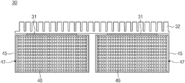
- FIGS. 9 through 12 illustrate a heat exchanger 30 according to a third exemplary form applied to a system for thermally managing a battery of the present disclosure.
- the heat exchanger 30 includes a heat exchange member 40 installed in the coolant circulation line 25 to exchange heat with a coolant, a thermoelectric element 31 attached to the heat exchange member 40 , a heat sink 32 attached to the thermoelectric element 31 , and a cooling fan 33 disposed to face the heat sink 32 .
- the heat exchange member 40 includes a heat exchange duct 45 connected in the middle of the coolant circulation line 25 .
- the heat exchange duct 45 has an inlet 45 a through which a coolant is introduced and an outlet 45 b through which the coolant is discharged, at both end portions thereof, and the inlet 45 a and the outlet 45 b of the heat exchange duct 45 have a cross-sectional area smaller than that of the heat exchange duct 45 .
- the inlet 45 a and the outlet 45 b are connected to one end and the other end of the heat exchange duct 45 by the medium of expansion type connection portions 49 , and each of the expansion type connection portions 49 have a tapered structure as illustrated in FIG. 12 .
- the heat exchange duct 45 is bent to have a U shape such that the inlet 45 a and the outlet 45 b are positioned in the same direction, and the coolant circulation line 25 is hermetically connected to the inlet 45 a and the outlet 45 b of the heat exchange duct 45 .
- a grid frame 47 is installed in an internal flow channel of the heat exchange duct 45 , and a plurality of grid flow channels 46 are formed at uniform intervals in vertical and horizontal directions in the grid frame 47 .
- Each of the grid flow channels 46 has a fine circular or quadrangular cross-section.
- two grid frames 47 are installed in the internal flow channel adjacent to the inlet 45 a of the heat exchange duct 45 and in the internal flow channel adjacent to the outlet 45 b of the heat exchange duct 45 , respectively.
- a coolant introduced through the inlet 45 a of the heat exchange duct 45 may pass through the grid flow channels 46 of the two grid frames 47 and is subsequently discharged through the outlet 45 b of the heat exchange duct 45 .
- the grid flow channels 46 may serve as heat exchange fins increasing a contact area of the coolant, and thus, heat exchange efficiency of the coolant may be increased.
- a baffle 48 having a plurality of small through holes 48 a is installed in the expansion type connection portion 49 .
- the small through holes 48 a of the baffle 48 are formed at uniform intervals, and thus, the inflow and outflow coolant may be uniformly distributed through the small through holes 48 a of the baffle 48 .
- thermoelectric element 31 may be attached to an upper surface or a lower surface of the heat exchange duct 45 , and in particular, a plurality of thermoelectric elements 31 may be uniformly attached to the upper surface or the lower surface of the heat exchange duct 45 to correspond to the U-shaped structure of the heat exchange duct 45 . Through the plurality of thermoelectric elements 31 , the coolant passing through the heat exchange duct 45 may be effectively cooled or heated.
- the thermal management of the battery may be effectively performed.
- thermoelectric element Since the coolant heat-exchanged with the battery is cooled or heated by using the Peltier effect of the thermoelectric element, a cooling structure and a heating structure for the battery may be unified, eliminating the necessity of association with a vehicle air-conditioning system, and thus, an overall layout may be very simplified, performance inspection may be simplified, and an overall weight may be effectively reduced.
- thermoelectric element since the coolant heat-exchanged with the battery is effectively cooled or heated by using the Peltier effect of the thermoelectric element, cooling and heating efficiency of the battery may be significantly enhanced.
- cooling and heating of the battery may be promptly switched by simply changing polarity of power applied to a thermoelectric element according to a temperature of the battery and a temperature of the coolant, controlling thereof may be simplified.
Landscapes
- Engineering & Computer Science (AREA)
- Manufacturing & Machinery (AREA)
- Chemical & Material Sciences (AREA)
- Chemical Kinetics & Catalysis (AREA)
- Electrochemistry (AREA)
- General Chemical & Material Sciences (AREA)
- Physics & Mathematics (AREA)
- Electromagnetism (AREA)
- Secondary Cells (AREA)
- Automation & Control Theory (AREA)
Abstract
Description
Claims (4)
Priority Applications (1)
| Application Number | Priority Date | Filing Date | Title |
|---|---|---|---|
| US16/422,362 US11217841B2 (en) | 2015-06-17 | 2019-05-24 | System and method for thermally managing battery |
Applications Claiming Priority (4)
| Application Number | Priority Date | Filing Date | Title |
|---|---|---|---|
| KR1020150085755A KR101836569B1 (en) | 2015-06-17 | 2015-06-17 | System and method for battery thermal management |
| KR10-2015-0085755 | 2015-06-17 | ||
| US14/943,918 US20160372806A1 (en) | 2015-06-17 | 2015-11-17 | System and method for thermally managing battery |
| US16/422,362 US11217841B2 (en) | 2015-06-17 | 2019-05-24 | System and method for thermally managing battery |
Related Parent Applications (1)
| Application Number | Title | Priority Date | Filing Date |
|---|---|---|---|
| US14/943,918 Division US20160372806A1 (en) | 2015-06-17 | 2015-11-17 | System and method for thermally managing battery |
Publications (2)
| Publication Number | Publication Date |
|---|---|
| US20190280356A1 US20190280356A1 (en) | 2019-09-12 |
| US11217841B2 true US11217841B2 (en) | 2022-01-04 |
Family
ID=57588505
Family Applications (2)
| Application Number | Title | Priority Date | Filing Date |
|---|---|---|---|
| US14/943,918 Abandoned US20160372806A1 (en) | 2015-06-17 | 2015-11-17 | System and method for thermally managing battery |
| US16/422,362 Active 2036-04-03 US11217841B2 (en) | 2015-06-17 | 2019-05-24 | System and method for thermally managing battery |
Family Applications Before (1)
| Application Number | Title | Priority Date | Filing Date |
|---|---|---|---|
| US14/943,918 Abandoned US20160372806A1 (en) | 2015-06-17 | 2015-11-17 | System and method for thermally managing battery |
Country Status (2)
| Country | Link |
|---|---|
| US (2) | US20160372806A1 (en) |
| KR (1) | KR101836569B1 (en) |
Cited By (2)
| Publication number | Priority date | Publication date | Assignee | Title |
|---|---|---|---|---|
| FR3140483A1 (en) | 2022-09-30 | 2024-04-05 | Airbus Helicopters | Electric energy generator equipped with a temperature regulation system cooperating with a fuel cell, and aircraft |
| US20250042221A1 (en) * | 2023-08-02 | 2025-02-06 | Hyundai Motor Company | Cooling apparatus and vehicle including the same |
Families Citing this family (21)
| Publication number | Priority date | Publication date | Assignee | Title |
|---|---|---|---|---|
| KR101734717B1 (en) * | 2015-12-11 | 2017-05-24 | 현대자동차주식회사 | Control Method Of Battery Module |
| US10910680B2 (en) * | 2016-01-27 | 2021-02-02 | Ford Global Technologies, Llc | Battery thermal management system including thermoelectric device |
| US10913369B2 (en) * | 2017-02-16 | 2021-02-09 | Ford Global Technologies, Llc | Charging energy recapture assembly and method |
| US9817074B1 (en) * | 2017-02-22 | 2017-11-14 | Bordrin Motor Corporation, Inc. | Method and apparatus for automatically computing work accuracy of a battery management system offline |
| CN107132865B (en) * | 2017-04-07 | 2020-03-27 | 上海蔚来汽车有限公司 | Active cooling power calibration method and system for energy storage unit of test vehicle |
| CN107453008B (en) * | 2017-09-14 | 2023-08-04 | 一汽-大众汽车有限公司 | Battery pack heating system for pure electric vehicle and control method thereof |
| BR112020005831A2 (en) * | 2017-10-06 | 2020-09-24 | Norma U.S. Holding Llc | thermal battery management tubing segment and assembly thereof |
| CN108054459B (en) * | 2017-11-02 | 2020-04-24 | 宁波吉利罗佑发动机零部件有限公司 | Thermal management system and thermal management method for vehicle battery pack |
| CN108091803B (en) * | 2018-01-18 | 2024-03-29 | 杭州捷能科技有限公司 | Integrated cooling heat-preserving battery system and control method thereof |
| KR101990592B1 (en) * | 2018-05-28 | 2019-06-18 | 한국기계연구원 | Phase change cooling module and battery pack using the same |
| WO2020004929A1 (en) * | 2018-06-29 | 2020-01-02 | 한국과학기술원 | Thermoelectric cooling method and device |
| CN111146517B (en) * | 2019-12-19 | 2020-12-01 | 珠海泰坦新动力电子有限公司 | Control method for battery formation into constant temperature equipment |
| KR102794057B1 (en) | 2020-01-30 | 2025-04-11 | 주식회사 엘지에너지솔루션 | Dehumidifier for Battery Pack and Battery Pack Comprising the same |
| CN111540927B (en) * | 2020-05-12 | 2021-06-04 | 郑州佛光发电设备有限公司 | Metal fuel cell system |
| KR102366924B1 (en) | 2020-07-22 | 2022-02-24 | 주식회사 신성일렉스 | System of solar type - obstacle light having battery cooling function |
| KR102686222B1 (en) * | 2020-10-16 | 2024-07-17 | 주식회사 엘지에너지솔루션 | Battery pack and vehicle comprising the same |
| KR20220052185A (en) | 2020-10-20 | 2022-04-27 | 현대자동차주식회사 | System and method for heating battery in vehicle using big data |
| CN115714220A (en) * | 2022-10-27 | 2023-02-24 | 中国第一汽车股份有限公司 | Battery thermal management system, battery assembly, electric vehicle and thermal management method |
| CN116387676A (en) * | 2023-02-21 | 2023-07-04 | 安徽明德源能科技有限责任公司 | Battery pack |
| CN118782971A (en) * | 2024-09-11 | 2024-10-15 | 南昌航空大学 | A high rate battery pack |
| CN119890527B (en) * | 2025-01-17 | 2025-10-14 | 武汉亿纬储能有限公司 | A battery pack |
Citations (13)
| Publication number | Priority date | Publication date | Assignee | Title |
|---|---|---|---|---|
| JP2000328981A (en) | 1999-05-21 | 2000-11-28 | Toyota Motor Corp | Engine control device |
| US20040135550A1 (en) | 2001-06-25 | 2004-07-15 | Hideo Nishihata | Temperature regulator of storage battery and vehicle including the same |
| US20060110657A1 (en) | 2004-11-15 | 2006-05-25 | William Stanton | Battery assembly for use in an uninterruptible power supply system and method |
| US20070248876A1 (en) * | 2005-11-03 | 2007-10-25 | Lg Chem , Ltd. | Sealed type heat exchanging system of battery pack |
| KR20080037159A (en) | 2006-10-25 | 2008-04-30 | 한라공조주식회사 | Automotive auxiliary air conditioning system using thermoelectric module |
| US20130078495A1 (en) | 2011-08-30 | 2013-03-28 | Tzu-Chin Chiu | Heating and cooling module for battery |
| JP2013084475A (en) | 2011-10-11 | 2013-05-09 | Toyota Industries Corp | Temperature control mechanism for battery |
| US20130183555A1 (en) * | 2012-01-17 | 2013-07-18 | Ford Global Technologies Llc | Cooling system for vehicle batteries |
| US20140090823A1 (en) | 2012-09-28 | 2014-04-03 | Behr Gmbh & Co. Kg | Heat exchanger |
| JP2014103734A (en) | 2012-11-19 | 2014-06-05 | Toyota Motor Corp | Thermoelectric generator |
| KR20140143816A (en) | 2012-04-04 | 2014-12-17 | 젠썸 인코포레이티드 | Temperature control systems with thermoelectric devices |
| US20150101354A1 (en) * | 2013-10-10 | 2015-04-16 | Hyundai Motor Company | Air conditioning system and method for high-voltage battery of vehicle |
| US20150244044A1 (en) * | 2014-02-25 | 2015-08-27 | Ford Global Technologies, Llc | Traction battery thermal plate manifold |
-
2015
- 2015-06-17 KR KR1020150085755A patent/KR101836569B1/en active Active
- 2015-11-17 US US14/943,918 patent/US20160372806A1/en not_active Abandoned
-
2019
- 2019-05-24 US US16/422,362 patent/US11217841B2/en active Active
Patent Citations (13)
| Publication number | Priority date | Publication date | Assignee | Title |
|---|---|---|---|---|
| JP2000328981A (en) | 1999-05-21 | 2000-11-28 | Toyota Motor Corp | Engine control device |
| US20040135550A1 (en) | 2001-06-25 | 2004-07-15 | Hideo Nishihata | Temperature regulator of storage battery and vehicle including the same |
| US20060110657A1 (en) | 2004-11-15 | 2006-05-25 | William Stanton | Battery assembly for use in an uninterruptible power supply system and method |
| US20070248876A1 (en) * | 2005-11-03 | 2007-10-25 | Lg Chem , Ltd. | Sealed type heat exchanging system of battery pack |
| KR20080037159A (en) | 2006-10-25 | 2008-04-30 | 한라공조주식회사 | Automotive auxiliary air conditioning system using thermoelectric module |
| US20130078495A1 (en) | 2011-08-30 | 2013-03-28 | Tzu-Chin Chiu | Heating and cooling module for battery |
| JP2013084475A (en) | 2011-10-11 | 2013-05-09 | Toyota Industries Corp | Temperature control mechanism for battery |
| US20130183555A1 (en) * | 2012-01-17 | 2013-07-18 | Ford Global Technologies Llc | Cooling system for vehicle batteries |
| KR20140143816A (en) | 2012-04-04 | 2014-12-17 | 젠썸 인코포레이티드 | Temperature control systems with thermoelectric devices |
| US20140090823A1 (en) | 2012-09-28 | 2014-04-03 | Behr Gmbh & Co. Kg | Heat exchanger |
| JP2014103734A (en) | 2012-11-19 | 2014-06-05 | Toyota Motor Corp | Thermoelectric generator |
| US20150101354A1 (en) * | 2013-10-10 | 2015-04-16 | Hyundai Motor Company | Air conditioning system and method for high-voltage battery of vehicle |
| US20150244044A1 (en) * | 2014-02-25 | 2015-08-27 | Ford Global Technologies, Llc | Traction battery thermal plate manifold |
Cited By (3)
| Publication number | Priority date | Publication date | Assignee | Title |
|---|---|---|---|---|
| FR3140483A1 (en) | 2022-09-30 | 2024-04-05 | Airbus Helicopters | Electric energy generator equipped with a temperature regulation system cooperating with a fuel cell, and aircraft |
| US20250042221A1 (en) * | 2023-08-02 | 2025-02-06 | Hyundai Motor Company | Cooling apparatus and vehicle including the same |
| US12496868B2 (en) * | 2023-08-02 | 2025-12-16 | Hyundai Motor Company | Cooling apparatus and vehicle including the same |
Also Published As
| Publication number | Publication date |
|---|---|
| US20160372806A1 (en) | 2016-12-22 |
| KR101836569B1 (en) | 2018-03-08 |
| KR20160148938A (en) | 2016-12-27 |
| US20190280356A1 (en) | 2019-09-12 |
Similar Documents
| Publication | Publication Date | Title |
|---|---|---|
| US11217841B2 (en) | System and method for thermally managing battery | |
| CN107785511B (en) | Battery modules, power battery packs and automobiles | |
| EP3849294B1 (en) | Cooling-heat dissipating case and heat dissipation control method | |
| KR100932214B1 (en) | Heat exchange system of battery pack using thermoelectric elements | |
| KR101428383B1 (en) | Device for cooling battery module of vehicle | |
| CN205028983U (en) | Power battery and car that has it | |
| CN103928729B (en) | A kind of electric automobile power battery group temperature control system based on heat pipe | |
| CN103959508B (en) | There is the battery system of the temperature control body comprising homoiothermic passage and bypass and comprise the motor vehicles of battery system | |
| TWI624102B (en) | Temperature-controlling/power-supplying system of battery pack | |
| KR101620185B1 (en) | Thermal managing unit and high-voltage battery | |
| CN207651636U (en) | A kind of automobile power cell packet heat management system and automobile | |
| CN105552474A (en) | Circular flow air cooling heat radiation device of power batteries | |
| CN105552268A (en) | Air-cooling battery box with cooling fins for multi-outlet electric vehicle batteries | |
| KR20170092982A (en) | Thermal management device for battery and Thermal management method for battery | |
| CN112510285A (en) | Heat dissipation method and device for vehicle battery module | |
| CN106410315A (en) | Two-way flow battery heat management system and battery heat adjustment method | |
| JP2021019369A5 (en) | ||
| CN117039269B (en) | Energy storage system and temperature control method thereof, and computer-readable storage medium | |
| CN219627381U (en) | High-power wireless charger and vehicle-mounted charging structure | |
| CN212412130U (en) | Power battery thermal management system with temperature adjustment function under cold and hot conditions | |
| CN217086707U (en) | Device for slowing down thermal runaway of battery pack | |
| CN205344440U (en) | Vehicle-mounted air-conditioning and heating device and vehicle | |
| CN108565374A (en) | Air-cooled battery case and the vehicle for including the air-cooled battery case | |
| CN215451537U (en) | Battery trays, battery packs and vehicles | |
| CN107020920A (en) | Vehicle-mounted air-conditioning and heating device, method, and vehicle |
Legal Events
| Date | Code | Title | Description |
|---|---|---|---|
| FEPP | Fee payment procedure |
Free format text: ENTITY STATUS SET TO UNDISCOUNTED (ORIGINAL EVENT CODE: BIG.); ENTITY STATUS OF PATENT OWNER: LARGE ENTITY |
|
| AS | Assignment |
Owner name: HYUNDAI MOTOR COMPANY, KOREA, REPUBLIC OF Free format text: ASSIGNMENT OF ASSIGNORS INTEREST;ASSIGNOR:HYUNDAI MOTOR COMPANY;REEL/FRAME:049581/0798 Effective date: 20190521 Owner name: KIA MOTORS CORPORATION, KOREA, REPUBLIC OF Free format text: ASSIGNMENT OF ASSIGNORS INTEREST;ASSIGNOR:HYUNDAI MOTOR COMPANY;REEL/FRAME:049581/0798 Effective date: 20190521 |
|
| STPP | Information on status: patent application and granting procedure in general |
Free format text: DOCKETED NEW CASE - READY FOR EXAMINATION |
|
| STPP | Information on status: patent application and granting procedure in general |
Free format text: NON FINAL ACTION MAILED |
|
| STPP | Information on status: patent application and granting procedure in general |
Free format text: RESPONSE TO NON-FINAL OFFICE ACTION ENTERED AND FORWARDED TO EXAMINER |
|
| STPP | Information on status: patent application and granting procedure in general |
Free format text: NOTICE OF ALLOWANCE MAILED -- APPLICATION RECEIVED IN OFFICE OF PUBLICATIONS |
|
| STPP | Information on status: patent application and granting procedure in general |
Free format text: PUBLICATIONS -- ISSUE FEE PAYMENT VERIFIED |
|
| STCF | Information on status: patent grant |
Free format text: PATENTED CASE |
|
| MAFP | Maintenance fee payment |
Free format text: PAYMENT OF MAINTENANCE FEE, 4TH YEAR, LARGE ENTITY (ORIGINAL EVENT CODE: M1551); ENTITY STATUS OF PATENT OWNER: LARGE ENTITY Year of fee payment: 4 |