US11217469B2 - Substrate transfer apparatus - Google Patents
Substrate transfer apparatus Download PDFInfo
- Publication number
- US11217469B2 US11217469B2 US16/874,015 US202016874015A US11217469B2 US 11217469 B2 US11217469 B2 US 11217469B2 US 202016874015 A US202016874015 A US 202016874015A US 11217469 B2 US11217469 B2 US 11217469B2
- Authority
- US
- United States
- Prior art keywords
- vacuum chamber
- vacuum
- arm unit
- unit
- support
- Prior art date
- Legal status (The legal status is an assumption and is not a legal conclusion. Google has not performed a legal analysis and makes no representation as to the accuracy of the status listed.)
- Active
Links
Images


Classifications
-
- H01L21/67742—
-
- H—ELECTRICITY
- H10—SEMICONDUCTOR DEVICES; ELECTRIC SOLID-STATE DEVICES NOT OTHERWISE PROVIDED FOR
- H10P—GENERIC PROCESSES OR APPARATUS FOR THE MANUFACTURE OR TREATMENT OF DEVICES COVERED BY CLASS H10
- H10P72/00—Handling or holding of wafers, substrates or devices during manufacture or treatment thereof
- H10P72/30—Handling or holding of wafers, substrates or devices during manufacture or treatment thereof for conveying, e.g. between different workstations
- H10P72/33—Handling or holding of wafers, substrates or devices during manufacture or treatment thereof for conveying, e.g. between different workstations into and out of processing chamber
- H10P72/3302—Mechanical parts of transfer devices
-
- B—PERFORMING OPERATIONS; TRANSPORTING
- B65—CONVEYING; PACKING; STORING; HANDLING THIN OR FILAMENTARY MATERIAL
- B65G—TRANSPORT OR STORAGE DEVICES, e.g. CONVEYORS FOR LOADING OR TIPPING, SHOP CONVEYOR SYSTEMS OR PNEUMATIC TUBE CONVEYORS
- B65G47/00—Article or material-handling devices associated with conveyors; Methods employing such devices
- B65G47/74—Feeding, transfer, or discharging devices of particular kinds or types
- B65G47/90—Devices for picking-up and depositing articles or materials
-
- H01L21/68707—
-
- H—ELECTRICITY
- H10—SEMICONDUCTOR DEVICES; ELECTRIC SOLID-STATE DEVICES NOT OTHERWISE PROVIDED FOR
- H10P—GENERIC PROCESSES OR APPARATUS FOR THE MANUFACTURE OR TREATMENT OF DEVICES COVERED BY CLASS H10
- H10P72/00—Handling or holding of wafers, substrates or devices during manufacture or treatment thereof
- H10P72/04—Apparatus for manufacture or treatment
- H10P72/0441—Apparatus for sealing, encapsulating, glassing, decapsulating or the like
-
- H—ELECTRICITY
- H10—SEMICONDUCTOR DEVICES; ELECTRIC SOLID-STATE DEVICES NOT OTHERWISE PROVIDED FOR
- H10P—GENERIC PROCESSES OR APPARATUS FOR THE MANUFACTURE OR TREATMENT OF DEVICES COVERED BY CLASS H10
- H10P72/00—Handling or holding of wafers, substrates or devices during manufacture or treatment thereof
- H10P72/04—Apparatus for manufacture or treatment
- H10P72/0451—Apparatus for manufacturing or treating in a plurality of work-stations
- H10P72/0464—Apparatus for manufacturing or treating in a plurality of work-stations characterised by the construction of the transfer chamber
-
- H—ELECTRICITY
- H10—SEMICONDUCTOR DEVICES; ELECTRIC SOLID-STATE DEVICES NOT OTHERWISE PROVIDED FOR
- H10P—GENERIC PROCESSES OR APPARATUS FOR THE MANUFACTURE OR TREATMENT OF DEVICES COVERED BY CLASS H10
- H10P72/00—Handling or holding of wafers, substrates or devices during manufacture or treatment thereof
- H10P72/06—Apparatus for monitoring, sorting, marking, testing or measuring
- H10P72/0606—Position monitoring, e.g. misposition detection or presence detection
-
- H—ELECTRICITY
- H10—SEMICONDUCTOR DEVICES; ELECTRIC SOLID-STATE DEVICES NOT OTHERWISE PROVIDED FOR
- H10P—GENERIC PROCESSES OR APPARATUS FOR THE MANUFACTURE OR TREATMENT OF DEVICES COVERED BY CLASS H10
- H10P72/00—Handling or holding of wafers, substrates or devices during manufacture or treatment thereof
- H10P72/70—Handling or holding of wafers, substrates or devices during manufacture or treatment thereof for supporting or gripping
- H10P72/76—Handling or holding of wafers, substrates or devices during manufacture or treatment thereof for supporting or gripping using mechanical means, e.g. clamps or pinches
- H10P72/7602—Handling or holding of wafers, substrates or devices during manufacture or treatment thereof for supporting or gripping using mechanical means, e.g. clamps or pinches the wafers being placed on a robot blade or gripped by a gripper for conveyance
-
- B—PERFORMING OPERATIONS; TRANSPORTING
- B65—CONVEYING; PACKING; STORING; HANDLING THIN OR FILAMENTARY MATERIAL
- B65G—TRANSPORT OR STORAGE DEVICES, e.g. CONVEYORS FOR LOADING OR TIPPING, SHOP CONVEYOR SYSTEMS OR PNEUMATIC TUBE CONVEYORS
- B65G47/00—Article or material-handling devices associated with conveyors; Methods employing such devices
- B65G47/74—Feeding, transfer, or discharging devices of particular kinds or types
- B65G47/90—Devices for picking-up and depositing articles or materials
- B65G47/904—Devices for picking-up and depositing articles or materials provided with rotary movements only
Definitions
- the present disclosure relates to a substrate transfer apparatus.
- Japanese Patent Application Publication No. 2013-77667 discloses a vacuum transfer apparatus in which a transfer robot is attached to a part of a wall of a vacuum chamber through an O-ring.
- the present disclosure provides a technique for suppressing a transfer error of a transfer robot even when a vacuum chamber is deformed.
- a vacuum transfer apparatus including: a vacuum chamber having a through-hole communicating with an outside; a transfer robot including an arm unit disposed in the vacuum chamber to support a substrate, a support unit configured to support the arm unit while passing through the through-hole with a gap between the support unit and the through-hole, and a base unit disposed at the outside of the vacuum chamber to support the support unit; and a bellows that surrounds a periphery of the support unit and is sealed and attached to the arm unit and an inner wall of the vacuum chamber around the through-hole.
- FIG. 1 shows an example of a schematic configuration of a vacuum transfer apparatus according to an embodiment
- FIGS. 2 and 3 show an example of a process of installing the vacuum transfer apparatus according to the embodiment.
- FIG. 4 shows an example of a measurement of the amount of lowering of a tip end of an arm unit according to the embodiment.
- FIG. 1 shows an example of a schematic configuration of a vacuum transfer apparatus 10 according to the embodiment.
- the vacuum transfer apparatus 10 according to the embodiment transfers a substrate in a depressurized state.
- a case where a semiconductor wafer (hereinafter, referred to as “wafer”) is used as an example of the substrate will be described as an example.
- the vacuum transfer apparatus 10 includes a vacuum chamber 20 .
- the vacuum chamber 20 has a flat box shape and a pressure therein can be decreased to a predetermined vacuum level by a vacuum pump (not shown).
- a through-hole 21 communicating with the outside is formed on the vacuum chamber 20 .
- an opening 22 is formed on a part of a wall forming a housing for the vacuum chamber 20 .
- the opening 22 is formed on a part of a wall forming a bottom surface of the vacuum chamber 20 .
- the opening 22 is sealed from the outside by a flat plate-shaped flange 23 .
- the flange 23 forms a part of a wall of a lower part of the vacuum chamber 20 .
- a through-hole 21 is formed in the flange 23 .
- the vacuum transfer apparatus 10 includes a transfer robot 30 .
- the transfer robot 30 is attached to the vacuum chamber 20 .
- the transfer robot 30 has an arm unit 31 , a support unit 32 , and a base unit 33 .
- the arm unit 31 is disposed in the vacuum chamber 20 .
- the arm unit 31 is configured as a multi-joint arm in which a plurality of arms 31 a is connected by joints 31 b .
- three arms 31 a are connected by the joints 31 b .
- the joints 31 b cause the arms 31 a to rotate in a horizontal direction.
- the arm unit 31 can be extended and contracted in the horizontal direction by rotating the arms 31 a through the joints 31 b and transfers the wafer W held by the leading arm 31 a.
- the arm unit 31 is supported by the support unit 32 .
- the support unit 32 is formed in a columnar shape to penetrate through the through-hole 21 .
- a predetermined gap is formed between the support unit 32 and a peripheral surface of the through-hole 21 .
- the arm unit 31 is supported by an upper end of the support unit 32 .
- a lower part of the support unit 32 is supported by the base unit 33 .
- the base unit 33 is disposed outside of the vacuum chamber 20 .
- the base unit 33 is fixed to a floor 72 by a bracket 71 .
- the base unit 33 is provided with a lifting mechanism 34 for raising and lowering the support unit 32 .
- the transfer robot 30 can raise and lower the arm unit 31 by raising and lowering the support unit 32 using the lifting mechanism 34 of the base unit 33 .
- a bellows 40 is disposed to surround a periphery of the support unit 32 .
- the bellows 40 has a lower end attached to an inner wall of the vacuum chamber 20 around the through-hole 21 and an upper end attached to the arm unit 31 .
- a gap between the lower end of the bellows 40 and the inner wall of the vacuum chamber 20 and a gap between the upper end of the bellows 40 and the arm unit 31 are respectively sealed by sealing members (not shown).
- the through-hole 21 is sealed by the bellows 40 and the arm unit 31 to prevent air from flowing into the vacuum chamber 20 through the through-hole 21 .
- the vacuum chamber 20 includes a transfer port 25 for transferring the wafer W.
- the transfer port 25 is connected to a processing chamber 50 through a bellows 51 .
- the processing chamber 50 includes a gate valve 52 .
- a gap between the bellows 51 and an outer wall of the vacuum chamber 20 and a gap between the bellows 51 and the gate valve 52 are respectively sealed by sealing members (not shown).
- the inner space of the processing chamber 50 can be depressurized to a predetermined vacuum level by a vacuum pump (not shown) and substrate processing is performed in the depressurized state.
- the substrate processing includes, e.g., film formation, etching, or the like.
- the substrate processing may be a processing that uses the plasma or a processing that does not use the plasma.
- the transfer robot 30 extends and contracts the arm unit 31 to transfer the wafer W from the transfer port 25 to the processing chamber 50 through the bellows 51 .
- the transfer robot 30 extends and contracts the arm unit 31 to transfer the wafer W from the transfer port 25 to the processing chamber 50 through the bellows 51 .
- the gate valve 52 is closed and the substrate processing is performed on the wafer W.
- the vacuum transfer apparatus 10 includes a controller 100 and a storage unit 101 .
- Each of the controller 100 and the storage unit 101 is, e.g., a computer.
- the storage unit 101 is configured to store various programs such as a control program for controlling the vacuum transfer apparatus 10 .
- the storage unit 101 is further configured to store various data such as processing conditions used in the program.
- the storage unit 101 stores correction information 101 a .
- the various programs and various data may be stored in a computer-readable storage medium (e.g., a hard disk, an optical disk such as a DVD or the like, a flexible disk, a semiconductor memory, or the like). Further, various programs and various data may be stored in another apparatus, and read out and used online through, e.g., a dedicated line.
- the controller 100 reads out the various programs such as the control program stored in the storage unit 101 and the like to control the operation of the vacuum transfer apparatus 10 .
- the controller 100 controls the operation of the arm unit 31 .
- the controller 100 controls the lifting mechanism 34 based on the correction information 101 a stored in the storage unit 101 .
- FIGS. 2 and 3 show an example of a process of installing the vacuum transfer apparatus 10 of the present embodiment.
- the base unit 33 of the transfer robot 30 is fixed to the flange 23 by a bracket 70 .
- the opening 22 of the vacuum chamber 20 has a size that allows the contracted arm unit 31 to pass therethrough.
- the transfer robot 30 is fixed to the vacuum chamber 20 by sealing the opening 22 with the flange 23 from the outside of the vacuum chamber 20 in a state where the arm unit 31 is passed through the opening 22 . Since the base unit 33 is fixed to the vacuum chamber 20 by the bracket 70 , the transfer robot 30 is moved together with the vacuum chamber 20 at the time of installing the vacuum transfer apparatus 10 .
- the transfer robot 30 can be arranged while maintaining the positional relationship between the transfer robot 30 and the vacuum chamber 20 .
- the transfer robot 30 can be positioned at a specific initial position relative to the vacuum chamber 20 .
- the base unit 33 is fixed to the vacuum chamber 20 by the bracket 70 , even if the vacuum chamber 20 and the transfer robot 30 are moved, it is possible to prevent the bellows 40 from being damaged by an excessive load.
- the base unit 33 is fixed to the floor 72 by the bracket 71 as shown in FIG. 3 . Accordingly, the arrangement position of the transport robot 30 is fixed. After the base unit 33 is fixed to the floor 72 by the bracket 71 , the bracket 70 is removed. By removing the bracket 70 , the transfer robot 30 is in a state where the base unit 33 is separated from the vacuum chamber 20 . Further, since the gap is present between the support unit 32 and the through-hole 21 , the support unit 32 is separated from the vacuum chamber 20 . Further, a portion where the base unit 33 is fixed to the floor 72 may be marked on the floor 72 . For example, in the case of replacing the transfer robot 30 , the base unit 33 is fixed to the floor 72 at the marked position on the floor 72 , so that the transfer robot 30 can be installed at the same position as that before the replacement.
- the vacuum chamber 20 and the processing chamber 50 are positionally aligned while being connected by a bracket 75 as shown in FIG. 2 .
- the bracket 75 is removed as shown in FIG. 3 .
- the vacuum chamber 20 and the processing chamber 50 are now connected by the bellows 51 . Accordingly, it is possible to suppress the stress caused by the deformation of the vacuum chamber 20 from being transmitted to the processing chamber 50 .
- the vacuum transfer apparatus 10 when the internal pressure of the vacuum chamber 20 is changed from an atmospheric pressure state to a vacuum state, the vacuum chamber 20 is deformed by the atmospheric pressure. Further, the temperature of the vacuum chamber 20 is changed by heat transferred from the substrate processing performed in the processing chamber 50 , and the vacuum chamber 20 is deformed by the temperature change.
- the vacuum transfer apparatus 10 when the vacuum chamber 20 is deformed, the stress caused by the deformation of the vacuum chamber 20 is transmitted to the transfer robot 30 , which may result in the changes in the position and the incline of the transfer robot 30 .
- the transfer position of the wafer W is changed even if the transfer robot 30 performs the same operation. Accordingly, a transfer error of the transfer robot 30 occurs.
- the number of the processing chambers 50 to be connected to the vacuum transfer apparatus 10 tends to increase and the size of the vacuum transfer apparatus 10 tends to increase.
- the increase in the size of the vacuum chamber 20 and the transfer robot 30 is necessary to transfer the wafer W in a vacuum state in a wider range.
- the increased size of the vacuum chamber 20 leads to an increase in the amount of deformation of the vacuum chamber 20 after evacuation, and the transfer error of the transfer robot 30 increases due to the deformation of the vacuum chamber 20 .
- the reduction in the amount of deformation of the vacuum chamber 20 by increasing a thickness of the wall of the vacuum chamber 20 is considered.
- the increase of a clearance between a transfer area of the transfer robot 30 and the inner wall of the vacuum chamber 20 is considered to prevent the arm unit 31 from colliding with the vacuum chamber 20 even if the transfer error increases.
- the increase of the height of the vacuum chamber 20 to increase the vertical movement range of the transfer robot 30 is considered.
- the vacuum transfer apparatus 10 has the problem in that the size of the vacuum chamber 20 is increased, thereby increasing the cost.
- the support unit 32 for supporting the arm unit 31 of the transfer robot 30 passes through the through-hole 21 with a gap between the support unit 32 and the through-hole 21 . Accordingly, the stress caused by the deformation of the vacuum chamber 20 is not transmitted to the support unit 32 , so that the position and the incline of the transfer robot 30 are not changed.
- the gap between the through-hole 21 and the support unit 32 is preferred to be greater than or equal to the amount of deformation of the vacuum chamber 20 . For example, the gap may be about several centimeters. As a result, the vacuum transfer apparatus 10 of the present embodiment can suppress the transfer error of the transfer robot 30 even when the vacuum chamber 20 is deformed.
- the bellows 40 is disposed to surround the periphery of the support unit 32 .
- the bellows 40 is sealed and attached to the arm unit 31 and the inner wall of the vacuum chamber 20 around the through-hole 21 . Therefore, the inside of the vacuum chamber 20 is blocked from the atmosphere and, thus, can be depressurized and maintained in a vacuum state. Further, since the bellows 40 is easily deformed, even if a portion of the vacuum chamber 20 to which one end of the bellows 40 is attached is deformed, the stress applied to a portion of the transfer robot 30 to which the other end of the bellows 40 is attached and the stress applied to the sealing portions at both ends of the bellows 40 are suppressed to be negligible.
- the vacuum transfer apparatus 10 of the present embodiment can maintain the vacuum state while suppressing the influence of the deformation of the vacuum chamber 20 on the transfer robot 30 .
- the transfer robot is attached to a part of a wall of the vacuum chamber through an O-ring as disclosed in Japanese Patent Application Publication No. 2013-77667, there is a trade-off relationship between a sealing performance and stress suppression due to a mechanism that absorbs the deformation of the vacuum chamber caused by the deformation of the O-ring.
- the base unit 33 is provided with the lifting mechanism 34 for vertically moving the support unit 32 .
- the lifting mechanism 34 is disposed on a vacuum side, e.g., inside the vacuum chamber 20 or the like, the lifting mechanism 34 may cause the generation of particles.
- the lifting mechanism 34 is disposed in the base unit 33 on an atmospheric pressure side, so that it becomes possible to suppress the particles caused by the lifting mechanism 34 from being generated in the vacuum chamber 20 even when the support unit 32 is vertically moved by the lifting mechanism 34 .
- the tip end of the arm unit 31 of the transfer robot 30 is lowered due to the influence of gravity.
- the amount of lowering of the tip end of the arm unit 31 is increased as the arm unit 31 is extended.
- correction information 101 a for correcting the lowering of the tip end of the arm unit 31 is stored in the storage unit 101 .
- the correction information 101 a is generated by extending and contracting the arm unit 31 of the transfer robot 30 under an atmospheric pressure state and measuring the position of the tip end of the arm unit 31 .
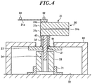
- FIG. 4 shows an example of the measurement of the lowering amount of the tip end of the arm unit 31 according to the embodiment.
- the transfer robot 30 is in the atmospheric pressure state without being attached to the vacuum chamber 20 .
- the transfer robot 30 is attached to a frame 90 that imitates the configuration of the lower part of the vacuum chamber 20 of the vacuum transfer apparatus 10 .
- the frame 90 is in the atmospheric pressure state.
- An opening 91 similar to the opening 22 is formed in the frame 90 .
- a marker 92 for position measurement is attached to multiple positions including the tip end of the arm unit 31 of the transfer robot 30 .
- the vertical positions of the markers 92 of the arm unit 31 are measured while extending and contracting the arm unit 31 of the transfer robot 30 , and the amount of lowering of the tip end of the arm unit 31 with respect to the amount of extension/contraction of the arm unit 31 is obtained.
- the correction information 101 a on the correction amount of the position of the tip end of the arm unit 31 with respect to the amount of extension/contraction of the arm unit 31 is generated from the amount of lowering of the tip end of the arm unit 31 with respect to the amount of extension/contraction of the arm unit 31 .
- the amount of lowering of the tip end of the arm unit 31 is stored as the correction amount in the correction information 101 a.
- the horizontal position of the tip end of the arm unit 31 is also changed as the tip end of the arm unit 31 is lowered.
- the change in the position of the tip end of the arm unit 31 due to the influence of gravity is greater in the vertical direction than in the horizontal direction. Therefore, in the present embodiment, the case of correcting the change in the vertical position is described.
- the present disclosure is not limited thereto and the change in the horizontal position may also be corrected.
- the amount of lowering of the tip end of the arm unit 31 together with the amount of change in the horizontal direction may be stored as the correction amount in the correction information 101 a .
- the position of the arm unit 31 in the horizontal direction may be corrected based on the stored amount of change in the horizontal direction.
- the lifting amount of the arm unit 31 required to correct the lowering of the tip end of the arm unit 31 may be stored as the correction amount in the correction information 101 a .
- the amount of lowering of the tip end of the arm unit 31 with respect to the amount of extension/contraction of the arm unit 31 may be measured in a state where the inside of the vacuum chamber 20 is set to the atmospheric pressure state after the transfer robot 30 is attached to the vacuum transfer apparatus 10 as shown in FIG. 1 .
- the transfer robot 30 is not affected by the deformation of the vacuum chamber 20 .
- the tip end of the arm unit 31 of the transfer robot 30 is lowered due to the influence of gravity even in the vacuum chamber 20 in a vacuum state as well as that in an atmospheric pressure state. Therefore, in the vacuum transfer apparatus 10 of the present embodiment, the correction information 101 a generated by measuring the lowering of the tip end of the arm unit 31 under the atmospheric pressure state can be used to correct the lowering of the tip end of the arm unit 31 in the vacuum chamber 20 maintained in the vacuum state.
- the controller 100 obtains the correction amount of the tip end of the arm unit 31 corresponding to the amount of extension/contraction of the arm unit 31 from the correction information 101 a stored in the storage unit 101 . Then, the controller 100 controls the lifting mechanism 34 to vertically move the arm unit 31 by the obtained correction amount. Therefore, the vacuum transfer apparatus 10 can correct the lowering of the tip end of the arm unit 31 due to the influence of gravity, which makes it possible to accurately control the arm unit 31 to a target position and to accurately transfer the substrate to a transfer position. Accordingly, the vacuum transfer apparatus 10 can reduce a clearance for the transfer position of the substrate, so that it is possible to suppress the increase in the size of the vacuum chamber 20 and the increase in cost.
- the vacuum transfer apparatus 10 of the present embodiment includes the vacuum chamber 20 , the transfer robot 30 , and the bellows 40 .
- the vacuum chamber 20 has the through-hole 21 communicating with the outside.
- the transfer robot 30 includes the arm unit 31 disposed in the vacuum chamber 20 to support the wafer W, the support unit 32 for supporting the arm unit 31 while passing through the through-hole 21 with a gap between the support unit 32 and the through-hole 21 , and the base unit 33 disposed at the outside of the vacuum chamber 20 to support the support unit 32 .
- the bellows 40 surrounds the periphery of the support unit 32 and is sealed and attached to the arm unit 31 and the inner wall of the vacuum chamber 20 around the through-hole 21 . Therefore, it becomes possible for the vacuum transfer apparatus 10 to suppress a transfer error of the transfer robot 30 even when the vacuum chamber 20 is deformed.
- the arm unit 31 may extend and contract in the horizontal direction.
- the base unit 33 includes the lifting mechanism 34 for vertically moving the support unit 32 .
- the vacuum transfer apparatus 10 may further include the storage unit 101 and the controller 100 .
- the storage unit 101 stores the correction information 101 a on the position of the tip end of the arm unit 31 with respect to the amount of extension/contraction of the arm unit 31 measured by extending and contracting the arm unit 31 under the atmospheric pressure state.
- the controller 100 controls the lifting mechanism 34 based on the correction information 101 a . Accordingly, it becomes possible for the vacuum transfer apparatus 10 to accurately control the arm unit 31 to the target position.
- the vacuum chamber 20 has the opening 22 formed on a part of the wall of the vacuum chamber 20 to communicate with the outside.
- the opening 22 is sealed by the flange 23 having the through-hole 21 .
- the transfer robot 30 can be attached to the vacuum chamber 20 in such a manner that the arm unit 31 enters into the vacuum chamber 20 through the opening 22 .
- the flange 23 by which the transfer robot 30 is fixed through a first fixing member (bracket 70 ), is attached to the vacuum chamber 20 to seal the opening 22 . Further, in the vacuum transfer apparatus 10 , after the transfer robot 30 is fixed to the floor by a second fixing member (bracket 71 ), the first fixing member is removed. Accordingly, the bellows 40 is prevented from being damaged when the vacuum transfer apparatus 10 is installed.
- the vacuum chamber 20 is connected to the processing chamber 50 through the bellows 51 , the processing chamber 50 being configured to perform substrate processing on the wafer W. Therefore, it becomes possible for the vacuum transfer apparatus 10 to suppress the stress caused by the deformation of the vacuum chamber 20 from being transmitted to the processing chamber 50 .
- the substrate is the wafer W
- the substrate is not limited thereto and may be other substrates such as a glass substrate and the like.
Landscapes
- Engineering & Computer Science (AREA)
- Mechanical Engineering (AREA)
- Robotics (AREA)
- Container, Conveyance, Adherence, Positioning, Of Wafer (AREA)
- Manipulator (AREA)
Abstract
Description
Claims (8)
Applications Claiming Priority (3)
| Application Number | Priority Date | Filing Date | Title |
|---|---|---|---|
| JP2019-093427 | 2019-05-17 | ||
| JPJP2019-093427 | 2019-05-17 | ||
| JP2019093427A JP2020188218A (en) | 2019-05-17 | 2019-05-17 | Vacuum transfer device |
Publications (2)
| Publication Number | Publication Date |
|---|---|
| US20200365438A1 US20200365438A1 (en) | 2020-11-19 |
| US11217469B2 true US11217469B2 (en) | 2022-01-04 |
Family
ID=73222954
Family Applications (1)
| Application Number | Title | Priority Date | Filing Date |
|---|---|---|---|
| US16/874,015 Active US11217469B2 (en) | 2019-05-17 | 2020-05-14 | Substrate transfer apparatus |
Country Status (2)
| Country | Link |
|---|---|
| US (1) | US11217469B2 (en) |
| JP (1) | JP2020188218A (en) |
Families Citing this family (3)
| Publication number | Priority date | Publication date | Assignee | Title |
|---|---|---|---|---|
| KR102931687B1 (en) * | 2021-09-28 | 2026-02-26 | 삼성디스플레이 주식회사 | Vacuum chamber having transferring unit for substrate |
| JP7785046B2 (en) | 2023-07-06 | 2025-12-12 | 株式会社安川電機 | robot |
| JP7707239B2 (en) * | 2023-07-06 | 2025-07-14 | 株式会社安川電機 | ROBOT AND SUBSTRATE TRANSFER DEVICE |
Citations (4)
| Publication number | Priority date | Publication date | Assignee | Title |
|---|---|---|---|---|
| US5522937A (en) * | 1994-05-03 | 1996-06-04 | Applied Materials, Inc. | Welded susceptor assembly |
| US6861614B1 (en) * | 1999-07-08 | 2005-03-01 | Nec Corporation | S system for the formation of a silicon thin film and a semiconductor-insulating film interface |
| JP2013077667A (en) | 2011-09-30 | 2013-04-25 | Hitachi High-Technologies Corp | Substrate transfer apparatus |
| US20180082879A1 (en) * | 2016-09-20 | 2018-03-22 | Wonik Ips Co., Ltd. | Substrate transfer apparatus and control method thereof |
-
2019
- 2019-05-17 JP JP2019093427A patent/JP2020188218A/en active Pending
-
2020
- 2020-05-14 US US16/874,015 patent/US11217469B2/en active Active
Patent Citations (4)
| Publication number | Priority date | Publication date | Assignee | Title |
|---|---|---|---|---|
| US5522937A (en) * | 1994-05-03 | 1996-06-04 | Applied Materials, Inc. | Welded susceptor assembly |
| US6861614B1 (en) * | 1999-07-08 | 2005-03-01 | Nec Corporation | S system for the formation of a silicon thin film and a semiconductor-insulating film interface |
| JP2013077667A (en) | 2011-09-30 | 2013-04-25 | Hitachi High-Technologies Corp | Substrate transfer apparatus |
| US20180082879A1 (en) * | 2016-09-20 | 2018-03-22 | Wonik Ips Co., Ltd. | Substrate transfer apparatus and control method thereof |
Also Published As
| Publication number | Publication date |
|---|---|
| JP2020188218A (en) | 2020-11-19 |
| US20200365438A1 (en) | 2020-11-19 |
Similar Documents
| Publication | Publication Date | Title |
|---|---|---|
| US11217469B2 (en) | Substrate transfer apparatus | |
| US11127614B2 (en) | Substrate transfer method and substrate transfer apparatus | |
| US11037810B2 (en) | Teaching method | |
| CN206022340U (en) | Substrate elevating lever actuator | |
| US20180068879A1 (en) | Front Opening Ring Pod | |
| US8943669B2 (en) | Assembly method for vacuum processing apparatus | |
| US10777439B1 (en) | Substrate processing apparatus | |
| TWI836026B (en) | Substrate lifting mechanism, substrate supporter and substrate processing device | |
| US10340175B2 (en) | Substrate transfer teaching method and substrate processing system | |
| JP2022058166A (en) | Reticle pod with anti-collision distance structure | |
| US20230117258A1 (en) | Substrate transfer apparatus and substrate transfer method | |
| US9310688B2 (en) | Processing apparatus and article manufacturing method using same | |
| KR20250108075A (en) | Substrate transfer system and image correction method | |
| JP5203102B2 (en) | Operation method of semiconductor processing equipment | |
| JP6296164B2 (en) | Robot system and transfer method | |
| JP7580228B2 (en) | Teaching apparatus, substrate transport apparatus, substrate processing apparatus, teaching method, and method for manufacturing electronic device | |
| KR102717514B1 (en) | Alignment apparatus, film forming apparatus, and adjusting method | |
| US8912513B2 (en) | Charged particle beam writing apparatus and charged particle beam writing method | |
| TW202132196A (en) | Substrate transfer method and apparatus | |
| JP7165806B2 (en) | SUBSTRATE PROCESSING APPARATUS, FACTOR PORT CLOSING UNIT AND METHOD OF MANUFACTURING SEMICONDUCTOR DEVICE | |
| JP5879234B2 (en) | Mask drawing apparatus and electron beam correction method | |
| US20230253223A1 (en) | Substrate processing apparatus and method for correcting positional displacement | |
| KR20250150482A (en) | Vacuum processing apparatus | |
| JP2024154175A (en) | Substrate transport mechanism control method and substrate processing system |
Legal Events
| Date | Code | Title | Description |
|---|---|---|---|
| FEPP | Fee payment procedure |
Free format text: ENTITY STATUS SET TO UNDISCOUNTED (ORIGINAL EVENT CODE: BIG.); ENTITY STATUS OF PATENT OWNER: LARGE ENTITY |
|
| STPP | Information on status: patent application and granting procedure in general |
Free format text: APPLICATION DISPATCHED FROM PREEXAM, NOT YET DOCKETED |
|
| AS | Assignment |
Owner name: TOKYO ELECTRON LIMITED, JAPAN Free format text: ASSIGNMENT OF ASSIGNORS INTEREST;ASSIGNOR:SATO, TAIKI;REEL/FRAME:053322/0153 Effective date: 20200713 |
|
| STPP | Information on status: patent application and granting procedure in general |
Free format text: DOCKETED NEW CASE - READY FOR EXAMINATION |
|
| STPP | Information on status: patent application and granting procedure in general |
Free format text: NON FINAL ACTION MAILED |
|
| STPP | Information on status: patent application and granting procedure in general |
Free format text: RESPONSE TO NON-FINAL OFFICE ACTION ENTERED AND FORWARDED TO EXAMINER |
|
| STPP | Information on status: patent application and granting procedure in general |
Free format text: NOTICE OF ALLOWANCE MAILED -- APPLICATION RECEIVED IN OFFICE OF PUBLICATIONS |
|
| STPP | Information on status: patent application and granting procedure in general |
Free format text: PUBLICATIONS -- ISSUE FEE PAYMENT VERIFIED |
|
| STCF | Information on status: patent grant |
Free format text: PATENTED CASE |
|
| MAFP | Maintenance fee payment |
Free format text: PAYMENT OF MAINTENANCE FEE, 4TH YEAR, LARGE ENTITY (ORIGINAL EVENT CODE: M1551); ENTITY STATUS OF PATENT OWNER: LARGE ENTITY Year of fee payment: 4 |