US11215836B2 - Deflector, display device, and method of manufacturing deflector - Google Patents
Deflector, display device, and method of manufacturing deflector Download PDFInfo
- Publication number
- US11215836B2 US11215836B2 US16/105,553 US201816105553A US11215836B2 US 11215836 B2 US11215836 B2 US 11215836B2 US 201816105553 A US201816105553 A US 201816105553A US 11215836 B2 US11215836 B2 US 11215836B2
- Authority
- US
- United States
- Prior art keywords
- support substrate
- curved
- holder
- fixing portion
- supported
- Prior art date
- Legal status (The legal status is an assumption and is not a legal conclusion. Google has not performed a legal analysis and makes no representation as to the accuracy of the status listed.)
- Active, expires
Links
- 238000004519 manufacturing process Methods 0.000 title claims description 9
- 239000000758 substrate Substances 0.000 claims abstract description 189
- 230000008878 coupling Effects 0.000 claims description 22
- 238000010168 coupling process Methods 0.000 claims description 22
- 238000005859 coupling reaction Methods 0.000 claims description 22
- 239000000463 material Substances 0.000 claims description 15
- 238000000034 method Methods 0.000 claims description 4
- 239000000109 continuous material Substances 0.000 claims 1
- 238000004026 adhesive bonding Methods 0.000 abstract description 9
- 230000003287 optical effect Effects 0.000 description 21
- 239000011347 resin Substances 0.000 description 18
- 229920005989 resin Polymers 0.000 description 18
- 230000008602 contraction Effects 0.000 description 17
- 239000010410 layer Substances 0.000 description 11
- 230000008859 change Effects 0.000 description 10
- 239000011295 pitch Substances 0.000 description 9
- 239000004952 Polyamide Substances 0.000 description 8
- 229920003229 poly(methyl methacrylate) Polymers 0.000 description 8
- 229920002647 polyamide Polymers 0.000 description 8
- 239000005020 polyethylene terephthalate Substances 0.000 description 8
- 229920000139 polyethylene terephthalate Polymers 0.000 description 8
- 239000004926 polymethyl methacrylate Substances 0.000 description 8
- 230000007613 environmental effect Effects 0.000 description 7
- 239000004417 polycarbonate Substances 0.000 description 4
- 229920000515 polycarbonate Polymers 0.000 description 4
- -1 polyethylene terephthalate Polymers 0.000 description 4
- 230000004907 flux Effects 0.000 description 3
- 229920003023 plastic Polymers 0.000 description 3
- 239000004033 plastic Substances 0.000 description 3
- 230000008569 process Effects 0.000 description 3
- VYPSYNLAJGMNEJ-UHFFFAOYSA-N Silicium dioxide Chemical compound O=[Si]=O VYPSYNLAJGMNEJ-UHFFFAOYSA-N 0.000 description 2
- 239000011230 binding agent Substances 0.000 description 2
- 230000000694 effects Effects 0.000 description 2
- 230000001788 irregular Effects 0.000 description 2
- 239000000178 monomer Substances 0.000 description 2
- 238000002834 transmittance Methods 0.000 description 2
- RTAQQCXQSZGOHL-UHFFFAOYSA-N Titanium Chemical compound [Ti] RTAQQCXQSZGOHL-UHFFFAOYSA-N 0.000 description 1
- 230000004075 alteration Effects 0.000 description 1
- 229910052782 aluminium Inorganic materials 0.000 description 1
- XAGFODPZIPBFFR-UHFFFAOYSA-N aluminium Chemical compound [Al] XAGFODPZIPBFFR-UHFFFAOYSA-N 0.000 description 1
- 239000012461 cellulose resin Substances 0.000 description 1
- 239000003086 colorant Substances 0.000 description 1
- 239000013078 crystal Substances 0.000 description 1
- 239000003822 epoxy resin Substances 0.000 description 1
- 239000000945 filler Substances 0.000 description 1
- 239000007788 liquid Substances 0.000 description 1
- 239000004973 liquid crystal related substance Substances 0.000 description 1
- 229910052751 metal Inorganic materials 0.000 description 1
- 239000002184 metal Substances 0.000 description 1
- 229920000058 polyacrylate Polymers 0.000 description 1
- 229920000647 polyepoxide Polymers 0.000 description 1
- 239000000377 silicon dioxide Substances 0.000 description 1
- 239000002356 single layer Substances 0.000 description 1
- 229910001220 stainless steel Inorganic materials 0.000 description 1
- 239000010935 stainless steel Substances 0.000 description 1
- 229920002803 thermoplastic polyurethane Polymers 0.000 description 1
- 239000010936 titanium Substances 0.000 description 1
- 229910052719 titanium Inorganic materials 0.000 description 1
Images


Classifications
-
- G—PHYSICS
- G02—OPTICS
- G02B—OPTICAL ELEMENTS, SYSTEMS OR APPARATUS
- G02B27/00—Optical systems or apparatus not provided for by any of the groups G02B1/00 - G02B26/00, G02B30/00
- G02B27/01—Head-up displays
- G02B27/017—Head mounted
- G02B27/0172—Head mounted characterised by optical features
-
- G—PHYSICS
- G02—OPTICS
- G02B—OPTICAL ELEMENTS, SYSTEMS OR APPARATUS
- G02B27/00—Optical systems or apparatus not provided for by any of the groups G02B1/00 - G02B26/00, G02B30/00
- G02B27/01—Head-up displays
- G02B27/017—Head mounted
- G02B27/0176—Head mounted characterised by mechanical features
-
- G—PHYSICS
- G02—OPTICS
- G02B—OPTICAL ELEMENTS, SYSTEMS OR APPARATUS
- G02B27/00—Optical systems or apparatus not provided for by any of the groups G02B1/00 - G02B26/00, G02B30/00
- G02B27/01—Head-up displays
- G02B27/0101—Head-up displays characterised by optical features
- G02B2027/011—Head-up displays characterised by optical features comprising device for correcting geometrical aberrations, distortion
-
- G—PHYSICS
- G02—OPTICS
- G02B—OPTICAL ELEMENTS, SYSTEMS OR APPARATUS
- G02B27/00—Optical systems or apparatus not provided for by any of the groups G02B1/00 - G02B26/00, G02B30/00
- G02B27/01—Head-up displays
- G02B27/0101—Head-up displays characterised by optical features
- G02B2027/013—Head-up displays characterised by optical features comprising a combiner of particular shape, e.g. curvature
-
- G—PHYSICS
- G02—OPTICS
- G02B—OPTICAL ELEMENTS, SYSTEMS OR APPARATUS
- G02B27/00—Optical systems or apparatus not provided for by any of the groups G02B1/00 - G02B26/00, G02B30/00
- G02B27/01—Head-up displays
- G02B27/0101—Head-up displays characterised by optical features
- G02B2027/0132—Head-up displays characterised by optical features comprising binocular systems
- G02B2027/0134—Head-up displays characterised by optical features comprising binocular systems of stereoscopic type
-
- G—PHYSICS
- G02—OPTICS
- G02B—OPTICAL ELEMENTS, SYSTEMS OR APPARATUS
- G02B27/00—Optical systems or apparatus not provided for by any of the groups G02B1/00 - G02B26/00, G02B30/00
- G02B27/01—Head-up displays
- G02B27/0149—Head-up displays characterised by mechanical features
- G02B2027/0169—Supporting or connecting means other than the external walls
-
- G—PHYSICS
- G02—OPTICS
- G02B—OPTICAL ELEMENTS, SYSTEMS OR APPARATUS
- G02B27/00—Optical systems or apparatus not provided for by any of the groups G02B1/00 - G02B26/00, G02B30/00
- G02B27/01—Head-up displays
- G02B27/017—Head mounted
- G02B27/0172—Head mounted characterised by optical features
- G02B2027/0174—Head mounted characterised by optical features holographic
-
- G—PHYSICS
- G02—OPTICS
- G02B—OPTICAL ELEMENTS, SYSTEMS OR APPARATUS
- G02B27/00—Optical systems or apparatus not provided for by any of the groups G02B1/00 - G02B26/00, G02B30/00
- G02B27/01—Head-up displays
- G02B27/017—Head mounted
- G02B2027/0178—Eyeglass type
-
- G—PHYSICS
- G02—OPTICS
- G02B—OPTICAL ELEMENTS, SYSTEMS OR APPARATUS
- G02B27/00—Optical systems or apparatus not provided for by any of the groups G02B1/00 - G02B26/00, G02B30/00
- G02B27/01—Head-up displays
- G02B2027/0192—Supplementary details
- G02B2027/0194—Supplementary details with combiner of laminated type, for optical or mechanical aspects
Definitions
- the disclosure relates to a deflector including a holographic element, a display device, and a method of manufacturing the deflector.
- JP-A-2015-191026 discloses a structure such that the holographic element is laminated on one face of a curved support substrate.
- JP-A-2015-191026 fails to disclose a structure such that the holographic element is fixed to a holder such as a holder for an eyeglasses frame.
- a holographic element 30 is laminated on a support substrate 20 including a curved portion 21 , a first flat portion 291 and a second flat portion 292 which are coupled to each other through a first bent portion 281 and a second bent portion 282 are provided in the curved portion 21 , and thus the first flat portion 291 and the second flat portion 292 are fixed to a first fixing portion 611 and a second fixing portion 612 of the holder 61 .
- the first bent portion 281 and the second bent portion 282 are located between the first fixing portion 611 and the second fixing portion 612 .
- This structure may cause the curved portion 21 to be heavily deformed between the first bent portion 281 and the second bent portion 282 in the support substrate 20 , when, for example, the support substrate 20 expands due to a change in environmental temperature.
- the holographic element 30 may also be heavily deformed as illustrated by the dashed line L 30 .
- the deformation may cause interference fringes 39 of the holographic element 30 to change from the state represented by the dotted line to the state represented by the solid line as illustrated in FIG. 19 , resulting in a significant change in diffraction angle.
- the disclosure provides a deflector, a display device, and a method of manufacturing the deflector, which are capable of suppressing the deformation of the holographic element.
- a deflector includes a support substrate including a curved portion that is curved along a first direction intersecting a thickness direction, the curved portion including a convex curved surface convex to a first side in the thickness direction, a holographic element laminated on at least one of a first surface and a second surface of the curved portion in the thickness direction, and configured to deflect and output light that is incident toward the curved portion, and a holder configured to hold the support substrate, wherein the holder includes a first fixing portion that overlaps with a first supported portion in the thickness direction and that fixed to the first supported portion, the first supported portion being a part of the curved portion on a first side in the first direction, and a second fixing portion that overlaps with a second supported portion an the thickness direction and that is fixed to the second supported portion, the second supported portion being a part of the curved portion on a second side in the first direction.
- the holographic element is laminated on the curved portion of the support substrate and configured to deflect and output light incident toward the curved portion.
- the first fixing portion and the second fixing portion of the holder overlap with the first supported portion and the second supported portion in the thickness direction and are fixed to the first supported portion and the second supported portion, respectively, the first supported portion and the second supported portion being spaced apart from each other in the first direction in the curved portion of the support substrate.
- the support substrate includes no bent portion between the first fixing portion and the second fixing portion of the holder (between the first supported portion and the second supported portion of the support substrate). Therefore, even when expansion or contraction occurs in the support substrate, the deformation of the support substrate in the first direction is suppressed by the holder. As a result, the deformation of the holographic element in the first direction is suppressed, thus making it hard to cause an incident such as a change in the diffraction angle of the holographic element in the first direction.
- an aspect such that the holder has a lower thermal expansion coefficient than the support substrate may be adopted. According to the aspect, even when expansion or contraction occurs in the support substrate due to a change in environmental temperature, the deformation of the support substrate is effectively suppressed by the holder.
- an aspect such that the holder has a higher elastic modulus than the support substrate may be adopted. According to the aspect, even when expansion or contraction occurs in the support substrate due to a change in environmental temperature, the deformation of the support substrate is effectively suppressed by the holder.
- an aspect may be adopted such that the first fixing portion is bent to overlap with a first side face that is a side face of the support substrate on the first side in the first direction and to be fixed to the first side face, and the second fixing portion is bent to overlap with a second side face that is a side face of the support substrate on the second side in the first direction and to be fixed to the second side face.
- the deformation of the support substrate is effectively suppressed by the holder.
- the support substrate in the first direction as a whole constitutes the curved portion may be adopted.
- the support substrate includes a first flat portion that is coupled to the curved portion on the first side in the first direction through a first bent portion, and the first fixing portion overlaps with the first supported portion and the first flat portion in the thickness direction and is fixed to the first supported portion and the first flat portion.
- the support substrate and the holder are fixed to each other through an overlapping part between the first fixing portion and the first flat portion.
- the support substrate includes a second flat portion that is coupled to the curved portion on the second side in the first direction through a second bent portion, and the second fixing portion overlaps with the second supported portion and the second flat portion in the thickness direction and is fixed to the second supported portion and the second flat portion.
- the support substrate and the holder are fixed to each other through an overlapping part between the second fixing portion and the second flat portion.
- the curved portion includes a central portion in the first direction, a width of the central portion in a second direction intersecting the first direction is longer than each of a width of the curved portion in the second direction on the first side in the first direction and a width of the curved portion in the second direction on the second side in the first direction, when viewed from the thickness direction.
- an aspect may be adopted such that a supporting film is laminated on a surface of the holographic element, the surface being on an opposite side to the support substrate in a region overlapping with the curved portion in the thickness direction.
- an aspect may be adopted such that a cover substrate is laminated on a surface of the supporting film, the surface being on an opposite side to the holographic element in a region overlapping with the curved portion in the thickness direction.
- an aspect such that the curved portion is curved along a second direction intersecting the first direction may be adopted.
- the holographic element deflects the light incident toward the curved portion in the first direction and the second direction.
- an aspect may be adopted such that the curved portion is curved along a second direction intersecting the first direction, the holographic element deflects the light incident toward the curved portion in the first direction and the second direction, the holder includes a third fixing portion configured to hold an end portion of the support substrate on a first side in the second direction intersecting both the first direction and the thickness direction and a fourth fixing portion configured to hold an end portion of the support substrate on a second side in the second direction, the third fixing portion overlaps with a third supported portion in the thickness direction and is fixed to the third supported portion, the third supported portion being a part of the curved portion on the first side in the second direction, and the fourth fixing portion overlaps with a fourth supported portion in the thickness direction and is fixed to the fourth supported portion, the fourth supported portion being a part of the curved portion on the second side in the second direction.
- the holographic element is configured to deflect and output in the first direction and the second direction the light incident toward the curved portion.
- the third fixing portion and the fourth fixing portion of the holder overlap with the third supported portion and the fourth supported portion in the thickness direction and are fixed to the third supported portion and the fourth supported portion, respectively, the third fixing portion and the fourth fixing portion being spaced apart from each other in the second direction in the curved portion of the support substrate.
- the support substrate includes no bent portion between the third fixing portion and the fourth fixing portion of the holder (between the third supported portion and the fourth supported portion of the support substrate), Therefore, even when expansion or contraction occurs in the support substrate, the deformation of the support substrate in the second direction is suppressed by the holder. As a result, the deformation of the holographic element in the second direction is suppressed, thus making it hard to cause an incident such that the diffraction angle of the holographic element in the second direction changes.
- One aspect of a display device includes the deflector to which the disclosure applies, and an image light projector configured to project image light from a second side in the thickness direction to the curved portion and from the first side in the first direction.
- the display device includes a frame configured to hold the support substrate and be mounted on the head of a viewer to position the holographic element in front of an eye of the viewer, and the holder is a part of the frame.
- the first direction is a left-and-right direction, and the thickness direction is a front-and-rear direction may be adopted.
- an aspect such that the first direction is an up-and-down direction, and the thickness direction is a front-and-rear direction may be adopted.
- One aspect of a method of manufacturing the deflector to which the disclosure applies includes forming a holographic material layer on the support substrate to form the holographic element, fixing a resulting support substrate to the holder, and performing interference exposure including illuminating the holographic material layer with an object beam and a reference beam.
- the deformation of the support substrate is suppressed by the holder.
- the deformation of the holographic element is suppressed, thus making it hard to cause an incident such that the diffraction angle of the holographic element changes.
- FIG. 1 illustrates an example of an appearance of a display device according to Exemplary Embodiment 1 of the disclosure.
- FIG. 2 illustrates an example of an optical system of the display device illustrated in FIG. 1 .
- FIG. 3 is a perspective view of a deflector according to Exemplary Embodiment 1 of the disclosure.
- FIG. 4 is a transverse sectional view of the deflector illustrated in FIG. 3 .
- FIG. 5 illustrates a holographic element included in the deflector illustrated in FIG. 3 .
- FIG. 6 illustrates a holographic element for a spherical wave.
- FIG. 7 is a transverse sectional view of a deflector according to Exemplary Embodiment 2 of the disclosure.
- FIG. 8 is a transverse sectional view of a deflector according to Exemplary Embodiment 3 of the disclosure.
- FIG. 9 is a transverse sectional view of a deflector according to Exemplary Embodiment 4 of the disclosure.
- FIG. 10 is a transverse sectional view of a deflector according to Exemplary Embodiment 5 of the disclosure.
- FIG. 11 is a transverse sectional view or a deflector according to Exemplary Embodiment 6 of the disclosure.
- FIG. 12 is a front view of a deflector according to Exemplary Embodiment 7 of the disclosure.
- FIG. 13 is a perspective view of a deflector according to Exemplary Embodiment 8 of the disclosure.
- FIG. 14 is a longitudinal sectional view of the deflector illustrated in FIG. 13 .
- FIG. 15 illustrates an example of an appearance of a display device according to Exemplary Embodiment 9 of the disclosure.
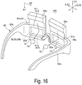
- FIG. 16 illustrates an example of an appearance of a display device according to Exemplary Embodiment 10 of the disclosure.
- FIG. 17 is a longitudinal sectional view of a deflector included in the display device illustrated in FIG. 16 .
- FIG. 18 is a transverse sectional view of a deflector included in a display device according to a reference example.
- FIG. 19 illustrates an issue in the reference example.
- a left-and-right direction (horizontal direction) is referred to as X
- an up-and-down direction as Y
- a front-and-rear direction as Z.
- FIG. 1 illustrates an example of an appearance of a display device 100 according to Exemplary Embodiment 1 of the disclosure.
- the display device 100 of Exemplary Embodiment 1 is configured to be a head mounted display device.
- the display device 100 includes a right-eye image light projector 50 a , right-eye holographic element 30 a that deflects image light emitted from the right-eye image light projector 50 a to make the image light enter a right eye Ea of a viewer, a left-eye image light projector 50 b , and a left-eye holographic element 30 b that deflects image light emitted from the left-eye image light projector 50 b to make the image light enter a left eye Eb of the viewer.
- the display device 100 has, for example, an eyeglasses shape.
- the display device 100 includes a frame 60 that holds the right-eye image light projector 50 a , the right-eye holographic element 30 a , the left-eye image light projector 50 b , and the left-eye holographic element 30 b , and the frame 60 is to be mounted on the head of the viewer.
- the frame 60 includes a right-eye holder 61 a that holds the right-eye holographic element 30 a and a left-eye holder 61 b that holds the left-eye holographic element 30 b .
- the frame 60 includes a right temple 62 a to be hooked to the right ear of the viewer and a left temple 62 b to be hooked to the left ear of the viewer, and the right-eye image light projector 50 a and the left-eye image light projector 50 b are attached to temples 62 a and 62 b , respectively.
- the right-eye holographic element 30 a is located in front of the right eye Ea
- the left-eye holographic element 30 b is located in front of the left eye Eb.
- FIG. 2 illustrates an example of an optical system of the display device 100 illustrated in FIG. 1 .
- a right-eye optical system 1 a between the right-eye image light projector 50 a and the right eye Ea and a left-eye optical system 1 b between the left-eye image light projector 50 b and the left eye Eb have the same basic configuration.
- FIG. 2 illustrates just the left-eye optical system 1 b , and explanation for the right-eye optical system 1 a is omitted.
- FIG. 2 also illustrates a beam at the center and beams at both ends of each angle of view of image light. To simplify the figure, the beams traveling after being reflected on a correction diffraction element 53 b are each represented by the central light beam of the corresponding angle of view, and the other beams are not illustrated.
- the left-eye image light projector 50 b includes an image light generator 51 b that emits image light L 0 and a projection optical system 52 b that projects the image light L 0 emitted from the image light generator 51 b .
- the left-eye image light projector 50 b includes the correction diffraction element 53 b and a correction optical system 54 b .
- An image generated by the image light generator 51 b passes through the projection optical system 52 b , the correction diffraction element 53 b , and the correction optical system 54 b to travel to the left-eye holographic element 30 b , and is then deflected toward the left eye Eb of the viewer by the left-eye holographic element 30 b.
- the image light generator 51 b includes a display panel such as an organic electroluminescent display device.
- the image light generator 51 b may be configured to include, as the display panel, a liquid crystal panel that modulates source light emitted from a light source (not illustrated).
- the projection optical system 52 b includes optical elements such as a lens and a mirror.
- the projection optical system 52 b has a function that controls an emission angle of the image light, and thus adjusts the beams of image light emitted at respective points on the image light generator 51 b to output collimated light fluxes having angles corresponding to the respective points.
- the correction diffraction element 53 b has the same basic configuration as the left-eye holographic element 30 b , and is formed from a reflective volume holographic element.
- the correction diffraction element 53 b corrects wavelength dependence of the left-eye holographic element 30 b for diffraction angles.
- the correction optical system 54 b includes optical elements such as a lens and a mirror.
- the correction optical system 54 b has a function that corrects an aberration of the image light L 0 such as distortion, thus effectively guiding the image light L 0 deflected by the correction diffraction element 53 b to the left-eye holographic element 30 b.
- the image light generator 51 b may include, for example, a light source, a scanning optical system that performs scanning with light flux emitted from the light source, and a light guide system.
- a laser device used as the light source emits light fluxes with light intensities modulated corresponding to the respective dots of an image to be displayed, and the scanning optical system performs two-dimensional scanning with modulated light emitted from the light source to generate the image.
- the left-eye holographic element 30 b is a refractive volume holographic element, and forms a partially transmissive combiner.
- natural light enters the left eye Eb through the left-eye holographic element 30 b , and accordingly the viewer recognizes an image in which image light L 0 a generated by the display device 100 is superimposed on the natural light (background).
- the left-eye holographic element 30 b is curved so that its convex curved surface is convex to a side opposite to the left eye Eb side of the viewer, and the left-eye image light projector 50 b projects the image light L 0 from the convex curved surface side of the left-eye holographic element 30 b.
- the left-eye holographic element 30 b , the left-eye holder 61 b , and a left-eye support substrate 20 b supported by the left-eye holder 61 b forms a left-eye deflector 10 b together, and the left-eye holographic element 30 b is laminated on one face of the left-eye support substrate 20 b in a thickness direction.
- the left-eye deflector 10 b described above and a right-eye deflector 10 a are symmetrically arranged and have the same basic configuration. Accordingly, in the following description, the left-eye deflector 10 b , the left-eye holder 61 b , the left-eye support substrate 20 b , and the left-eye holographic element 30 b are referred to as a deflector 10 , a holder 61 , a support substrate 20 , and a holographic element 30 , respectively, regardless of whether those are each for the left eye or the right eye.
- a first direction is referred to as X 1
- Y 1 a second direction
- the thickness direction of the support substrate 20 as Z 1 .
- one side in the first direction X 1 is referred to as X 1 a , the other side as X 1 b , one side in the second direction Y 1 as Y 1 a , the other side in the second direction Y 1 as Y 1 b , one side in the thickness direction Z 1 as Z 1 a , and the other side in the thickness direction Z 1 as Z 1 b .
- the first direction X 1 corresponds to an X direction left- and right direction, horizontal direction) in FIG. 1
- the second direction Y 1 corresponds to a Y direction (up-and-down direction) in FIG. 1
- the third direction Z 1 corresponds to a Z direction (front-and-rear direction) in FIG. 1
- the one side Z 1 a corresponds to a side opposite to the eye of the viewer
- the other side Z 1 b is located on a side with the eye of the viewer.
- FIG. 3 is a perspective view of the deflector 10 according to Exemplary Embodiment 1 of the disclosure
- FIG. 4 is a transverse sectional view of the deflector 10 illustrated in FIG. 3
- the deflector 10 of Exemplary Embodiment 1 includes the support substrate 20 that is light transmissive, the holographic element 30 that is laminated on the support substrate 20 , and the holder 61 that holds the support substrate 20 .
- the support substrate 20 includes a curved portion 21 that is curved along the first direction X 1 intersecting the thickness direction Z 1 , and the curved portion 21 includes a convex curved surface 210 convex to the one side Z 1 a in the thickness direction Z 1 .
- the holographic element 30 is laminated on a face (one side face 211 ) of the curved portion 21 on the one side Z 1 a in the thickness direction Z 1 or on a face (other side face 212 ) on the other side Z 1 b , and the holographic element 30 also deflects, in the first direction X 1 , light L incident toward the curved portion 21 from the other side Z 1 b in the thickness direction Z 1 , outputting the light L.
- the holographic element 30 is laminated on the one side face 211 made up of the convex curved surface 210 .
- the holographic element 30 is curved so that the convex curved surface is located on the one side Z 1 a in the thickness direction Z 1 .
- the curved portion 21 is also curved along the second direction Y 1 intersecting both the thickness direction Z 1 and the first direction X 1 .
- the holographic element 30 also deflects, in the second direction Y 1 , the light L incident toward the curved portion 21 from the other side Z 1 b in the thickness direction Z 1 , outputting the light L.
- a size in the first direction X 1 is larger than a size in the second direction Y 1 .
- a deflection angle range (diffraction angle range) in the first direction X 1 is wider than a deflection angle range (diffraction angle range) in the second direction Y 1 .
- the holder 61 in Exemplary Embodiment 1 is configured as follows.
- the holder 61 includes a first fixing portion 611 that supports a part of the support substrate 20 on the one side X 1 a in the first direction X 1 and a second fixing portion 612 that supports a part of the support substrate 20 on the other site X 1 b in the first direction X 1 .
- the holder 61 also includes a first coupling portion 613 that couples one end of the first fixing portion 611 and one end of the second fixing portion 612 on the one side Y 1 a in the second direction Y 1 and a second coupling portion 614 that couples the other end of the first fixing portion 611 and the other end of the second fixing portion 612 on the other side 1 b in the second direction Y 1 .
- the holder 61 includes an opening 610 surrounded by the first fixing portion 611 , the second fixing portion 612 , the first coupling portion 613 , and the second coupling portion 614 .
- the first fixing portion 611 overlaps with a first supported portion 216 that is a part of the curved portion 21 of the support substrate 20 on the one side X 1 a in the first direction X 1 from the other side Z 1 b in the thickness direction Z 1 , and is fixed to the first supported portion 216 by, for example, adhesive bonding.
- the second fixing portion 612 overlaps with a second supported portion 217 that is a part of the curved portion 21 of the support substrate 20 on the other side X 1 b in the first direction X 1 from the other side Z 1 b in the thickness direction Z 1 , and is fixed to the second supported portion 217 by, for example, adhesive bonding. Accordingly, the support substrate 20 is continuously curved between the first supported portion 216 and the second supported portion 217 (between the first fixing portion 611 and the second fixing portion 612 ), and thus includes no bent portion.
- the support substrate 20 in the first direction X 1 as a whole forms the curved portion 21 .
- the first supported portion 216 is an end portion of the curved portion 21 on the one side X 1 a in the first direction X 1
- the second supported portion 217 is an end portion of the curved portion 21 on the other side X 1 b in the first direction X 1 .
- the first supported portion 216 and the second supported portion 217 each form a part of the curved portion 21 as a whole, thus having a curved shape or a slanted shape as a whole.
- the first fixing portion 611 and the second fixing portion 612 each have a curved shape or a slanted shape as a whole, as with the first supported portion 216 and the second supported portion 217 .
- the first coupling portion 613 extends in the first direction X 1 at a position apart from the support substrate 20 on the one side Y 1 a in the second direction Y 1
- the second coupling portion 614 extends in the first direction X 1 at a position apart from the support substrate 20 on the other side Y 1 b in the second direction Y 1
- the first coupling portion 613 and the second coupling portion 614 may have a linear shape extending in the first direction X 1
- the first coupling portion 613 and the second coupling portion 614 are each curved along the first direction X 1 to conform to the curved portion 21 of the support substrate 20 .
- the support substrate 20 is formed from a plastic material, such as polymethyl methacrylate (PMMA) resin, polycarbonate (PC) resin, polyethylene terephthalate (PET) resin, and polyamide (PA) resin, and has a thickness of 500 ⁇ m to 5000 ⁇ m.
- the holder 61 is formed from a metal such as titanium, stainless steel, and aluminum, or a plastic material in which fillers such as silica are embedded. Consequently, the support substrate 20 and the holder 61 differ in thermal expansion coefficient. Furthermore, the support substrate 20 and the holder 61 differ in elastic modulus. For example the thermal expansion coefficient of the support substrate 20 is 60 ppm/° C. to 80 ppm/° C.
- the thermal expansion coefficient of the holder 61 is 30 ppm/° C. or less, and thus the thermal expansion coefficient of the holder 61 is lower than the thermal expansion coefficient of the support substrate 20 .
- the elastic modulus of the support substrate 20 is 350 kg/mm 2 or less while the elastic modulus of the holder 61 is 1000 kg/mm 2 or more, and thus the elastic modulus of the holder 61 is higher than the elastic modulus of the support substrate 20 .
- the holographic element 30 is formed from a layer obtained in such a manner that a holographic material in which photosensitive monomers such as acrylic polymers are dispersed in a binder resin such as urethane resin, epoxy resin and cellulose resin, is applied to the support substrate 20 , and is then subjected to interference exposure, and thus interference fringes 39 illustrated in FIG. 18 are recorder as changes, such as changes in refractive index, changes in transmittance, and changes in shapes such as irregular patterns, in the holographic element 30 .
- a holographic material in which photosensitive monomers such as acrylic polymers are dispersed in a binder resin such as urethane resin, epoxy resin and cellulose resin is applied to the support substrate 20 , and is then subjected to interference exposure, and thus interference fringes 39 illustrated in FIG. 18 are recorder as changes, such as changes in refractive index, changes in transmittance, and changes in shapes such as irregular patterns, in the holographic element 30 .
- the holographic element 30 has a thickness of 5 ⁇ m to 25 ⁇ m and an elastic modulus of 350 kg/mm 2 or less.
- the elastic modulus of the holographic element 30 is lower than the elastic modulus of the support substrate 20 .
- the first fixing portion 611 and the second fixing portion 612 of the holder 61 overlap with the first supported portion 216 and the second supported portion 217 in the thickness direction Z 1 and are fixed to the first supported portion 216 and the second supported portion 217 , respectively, the first supported portion 216 and the second supported portion 217 being spaced apart from each other in the first direction X 1 in the curved portion 21 of the support substrate 20 , Accordingly, the support substrate 20 includes no bent portion between the first fixing portion 611 and the second fixing portion 612 of the holder 61 (between the first supported portion 216 and the second supported portion 217 of the support substrate 20 ).
- the deformation of the support substrate 20 in the first direction X 1 is suppressed by the holder 61 .
- the deformation of the holographic element 30 in the first direction X 1 is suppressed, thus making it hard to cause an incident such that the diffraction angle of the holographic element 30 in the first direction X 1 changes.
- the holder 61 in Exemplary Embodiment 1 has a lower thermal expansion coefficient than the support substrate 20 . Therefore, even when expansion or contraction occurs in the support substrate 20 due to a change in environmental temperature, the deformation of the support substrate 20 is effectively suppressed by the holder 61 .
- the holder 61 has a higher elastic modulus than the support substrate 20 . Therefore, even when expansion or contraction occurs in the support substrate 20 due to a change in environmental temperature, the deformation of the support substrate 20 is effectively suppressed by the holder 61 .
- FIG. 5 illustrates the holographic element 30 included in the deflector 10 illustrated in FIG. 3 .
- FIG. 6 illustrates the holographic element 30 for a spherical wave.
- a holographic material layer 35 in which the holographic element 30 is formed is laminated on the support substrate 20 , a resulting support substrate 20 is fixed to the holder 61 , the holographic material layer 35 is subjected to interference exposure accordingly, and then heated. As a result, the photosensitive monomers are cured while forming the interference fringes 39 , and such a state is fixed by the binder resin.
- the holographic material layer 35 is subjected to interference exposure with a reference beam Lr and an object beam Ls, and thus the interference fringes 39 as illustrated in FIG. 18 are formed.
- the object beam Ls is a plane wave
- a plurality of linear interference fringes are formed so that they are aligned in parallel.
- red light (R), green light (G), and blue light (B) enter the holographic element 30 , and the holographic element 30 diffracts and outputs the beams of color light in a certain direction.
- first interference fringes 39 (R) having pitches each corresponding to the wavelength of the red light (R), second interference fringes 39 (G) having pitches each corresponding to the wavelength of the green light (G), and third interference fringes 39 (B) having pitches each corresponding to the wavelength of the blue light (B) are laminated in the thickness direction.
- the pitch corresponding to the wavelength of the red light (R) is longer than the pitch corresponding to the wavelength of the green light (G) and the pitch corresponding to the wavelength of the blue light (B), and the pitch corresponding to the wavelength of the green light (G) is longer than the pitch corresponding to the wavelength of the blue light (B).
- the interference fringes 39 are each recorded as changes such as changes in refractive index, changes in transmittance, and changes in shapes such as irregular patterns, in the holographic material layer 35 .
- the interference fringes 39 are inclined to an incident surface of the holographic element 30 in one direction. For example, when a light beam L 1 that is a spherical wave with single wavelength enters the holographic element 30 in the normal direction, a light beam L 2 that is a spherical wave with the highest diffraction efficiency in one direction is output from the holographic element 30 .
- FIG. 5 illustrates a state where the first interference fringes 39 (R), the second interference fringes 39 (G), and the third interference fringes 39 (B) are each formed in a different layer so that the first interference fringes 39 (R), the second interference fringes 39 (G), and the third interference fringes 39 (B) are clearly seen.
- two or more types of interference fringes may be formed in a single layer, which is subjected to simultaneous interference exposure with light including light beams of two or more colors.
- a spherical wave is used as the object beam Ls for interference exposure, for example.
- a plurality of curved interference fringes are formed so that they are aligned in parallel.
- the light beam L 1 that is a spherical wave with single wavelength enters the holographic element 30 in the normal direction
- the light beam L 2 that is a spherical wave with the highest diffraction efficiency in one direction is output from the holographic element 30 .
- the manufacturing method during the process of interference exposure or related processes, expansion or contraction occurs in the holographic material layer 35 , which causes the support substrate 20 to warp.
- the interference fringes 39 shift from the positions represented by the dotted lines to the positions represented by the solid lines as described with reference to FIG. 18 .
- the first fixing portion 611 and the second fixing portion 612 of the holder 61 overlap with the first supported portion 216 and the second supported portion 217 in the thickness direction Z 1 and are fixed to the first supported portion 216 and the second supported portion 217 , respectively, the first supported portion 216 and the second supported portion 217 being spaced apart from each other in the first direction X 1 in the curved portion 21 of the support substrate 20 .
- the support substrate 20 includes no bent portion between the first fixing portion 611 and the second fixing portion 612 of the holder 61 (between the first supported portion 216 and the second supported portion 217 of the support substrate 20 ).
- the deformation of the support substrate 20 in the first direction X 1 is suppressed by the holder 61 , thus making it hard for the holographic material layer 35 to expand or contract.
- the holder 61 in Exemplary Embodiment 1 has a higher elastic modulus than the support substrate 20 , Accordingly, the deformation of the support substrate 20 in the first direction X 1 is effectively suppressed by the holder 61 , and it is hard for the interference fringes 39 of the holographic element 30 to be deformed in the first direction X 1 , thus making it hard to cause an incident such that the diffraction angle in the first direction X 1 changes.
- FIG. 7 is a transverse sectional view of a deflector 10 according to Exemplary Embodiment 2 of the disclosure.
- the basic configuration of Exemplary Embodiment 2 and the other exemplary embodiments describe later is identical to that of Exemplary Embodiment 1, and thus like reference characters refer to similar elements, and their description will not be repeated.
- the first fixing portion 611 and the second fixing portion 612 of the holder 61 support only the other side face 212 of the curved portion 21 of the support substrate 20 .
- the first fixing portion 611 is bent to overlap with a first side face 26 that is a side face of the support substrate 20 on the one side X 1 a in the first direction X 1 , and is fixed to the first side face 26 by, for example, adhesive bonding.
- the second fixing portion 612 is bent to overlap with a second side face 27 that is a side face of the support substrate 20 on the other side X 1 b in the first direction X 1 , and is fixed to the second side face 27 by, for example, adhesive bonding.
- the other configuration is identical to that of Exemplary Embodiment 1.
- both side faces of the support substrate 20 in the first direction X 1 are fixed by the holder 61 . Therefore, the deformation of the support substrate 20 in the first direction X 1 , such as expansion and contraction, is effectively suppressed by the holder 61 . As a result, the deformation of the holographic element 30 in the first direction X 1 is effectively suppressed.
- FIG. 8 is a transverse sectional view of a deflector 10 according to Exemplary Embodiment 3 of the disclosure.
- the support substrate 20 in the first direction X 1 as a whole forms the curved portion 21 .
- the support substrate 20 includes a first flat portion 291 that is coupled to the curved portion 21 on the one side X 1 a in the first direction X 1 through a first bent portion 281 .
- the support substrate 20 also includes a second flat portion 292 that is coupled to the curved portion 21 on the other side X 1 b in the first direction X 1 through a second bent portion 282 .
- the first fixing portion 611 of the holder 61 is bent at a position corresponding to the first bent portion 281 of the support substrate 20 , overlaps with the first supported portion 216 , which is an end portion of the curved portion 21 , and the first flat portion 291 in the thickness direction Z 1 , and is fixed to the first supported portion 216 and the first flat portion 291 .
- the second fixing portion 612 of the holder 61 is bent at a position corresponding to the second bent portion 282 of the support substrate 20 , overlaps with the second supported portion 217 , which is an end portion of the curved portion 21 , and the second portion 292 in the thickness direction Z 1 , and is fixed to the second supported portion 217 and the second flat portion 292 .
- the other configuration is identical to that of Exemplary Embodiment 1.
- the support substrate 20 includes the first flat portion 291 and the second flat portion 292 , while the support substrate 20 includes no bent portion between the first fixing portion 611 and the second fixing portion 612 of the holder 61 (between the first supported portion 216 and the second supported portion 217 of the support substrate 20 ).
- Exemplary Embodiment 3 has the same advantageous effect as Exemplary Embodiment 1, including the deformation of the holographic element 30 in the first direction X 1 being suppressed.
- FIG. 9 is a transverse sectional view of a deflector 10 according to Exemplary Embodiment 4 of the disclosure.
- the first fixing portion 611 and the second fixing portion 612 of the holder 61 support only the face of the support substrate 20 on the other side Z 1 b in the thickness direction 11 .
- the first fixing portion 611 is bent to overlap with the first side face 26 that is a side face of the support substrate 20 on the one side X 1 a in the first direction X 1 , and is fixed to the first side face 26 by, for example, adhesive bonding.
- the second fixing portion 612 is bent to overlap with the second side face 27 that is a side face of the support substrate 20 on the other side X 1 b in the first direction X 1 , and is fixed to the second side face 27 by, for example, adhesive bonding.
- the other configuration is identical to that of Exemplary Embodiment 1.
- both side faces of the support substrate 20 in the first direction X 1 are fixed by the holder 61 , Therefore, the deformation of the support substrate 20 in the first direction X 1 , such as expansion and contraction, is effectively suppressed by the holder 61 . As a result, the deformation of the holographic element 30 in the first direction X 1 is effectively suppressed.
- FIG. 10 is a transverse sectional view of a deflector 10 according to Exemplary Embodiment 5 of the disclosure.
- the holographic element 20 is exposed on an opposite side to the support substrate 20 .
- a light transmissive support film 41 is laminated on the holographic element 30 on the opposite side to the support substrate 20 in a region that overlaps with the curved portion 21 of the support substrate 20 in the thickness direction Z 1 .
- the support film 41 has the same size as the holographic element 30 .
- the support film 41 is a film formed from, for example, polymethyl methacrylate (PMMA) resin, polycarbonate (PC) resin, polyethylene terephthalate (PET) resin, or polyamide (PA) resin, as with the support substrate 20 .
- the support film 41 has a thickness of 50 ⁇ m to 3000 ⁇ m, and also has a thermal expansion coefficient and an elastic modulus which are approximately the same as those of the support substrate 20 .
- the other configuration is identical to that of Exemplary Embodiment 1.
- the support substrate 20 includes no bent portion between the first fixing portion 611 and the second fixing portion 612 of the holder 61 (between the first supported portion 216 and the second supported portion 217 of the support substrate 20 ). Therefore, even when expansion or contraction occurs in the support substrate 20 , the deformation of the support substrate 20 is suppressed by the holder 61 .
- Exemplary Embodiment 5 has the same advantageous effect as Exemplary Embodiment 1, including the deformation of the holographic element 30 and a cover substrate 40 in the first direction X 1 being suppressed.
- the structure using the cover substrate 40 of Exemplary Embodiment 5 may apply to not only Exemplary Embodiment 1 but also Exemplary Embodiment 2 to Exemplary Embodiment 4.
- FIG. 11 is a transverse sectional view of a deflector 10 according to Exemplary Embodiment 6 of the disclosure.
- a light transmissive support film 41 is laminated on the holographic element 30 , on the opposite side to the support substrate 20 in a region that overlaps with the curved portion 21 of the support substrate 20 in the thickness direction Z 1 , as in Exemplary Embodiment 5.
- a cover substrate 42 that is light transmissive is laminated on the support film. 41 , on the opposite side to the holographic element 30 in a region that overlaps with the curved portion 21 of the support substrate 20 in the thickness direction Z 1 .
- the cover substrate 42 is larger than the holographic element 30 and has the same size as a portion of the support substrate 20 that supports the holographic element 30 .
- the cover substrate 42 is a substrate formed from, for example, polymethyl methacrylate (PMMA) resin, polycarbonate (PC) resin, polyethylene terephthalate (PET) resin, or polyamide (PA) resin, as with the support substrate 20 .
- the cover substrate 42 is formed from a plastic material, such as polymethyl methacrylate (PMMA) resin, polycarbonate (PC) resin, polyethylene terephthalate (PET) resin, and polyamide (PA) resin, as with the support substrate 20 , and has a thickness of 50 ⁇ m to 5000 ⁇ m.
- the cover substrate 42 has a thermal expansion coefficient and an elastic modulus which are approximately the same as those of the support substrate 20 .
- the other configuration is identical to that of Exemplary Embodiment 1.
- the structure using the cover substrate 42 of Exemplary Embodiment 6 may apply to not only Exemplary Embodiment 1 but also Exemplary Embodiment 2 to Exemplary Embodiment 4.
- FIG. 12 is a front view of a deflector 10 according to Exemplary Embodiment 7 of the disclosure.
- each of the support substrate 20 and the holographic element 30 has an equal width in the second direction Y 1 at any position in the first direction X 1 .
- Exemplary Embodiment 7 as illustrated in FIG.
- the curved portion 21 of the support substrate 20 and the holographic element 30 each have widths such that a width in the second direction Y 1 in a central portion in the first direction X 1 is wider than each of a width in the second direction Y 1 on the one side X 1 a in the first direction X 1 and a width in the second direction Y 1 on the other side X 1 b in the first direction X 1 . Accordingly, the first coupling portion 613 and the second coupling portion 614 of the holder 61 are curved outward in the second direction Y 1 and along the first direction X 1 .
- the other configuration is identical to that of Exemplary Embodiment 1,
- the structure using the curved portion 21 of the support substrate 20 and the shape of the holographic element 30 in Exemplary Embodiment 7 may apply to not only Exemplary Embodiment 1 but also Exemplary Embodiment 2 to Exemplary Embodiment 6.
- FIG. 13 is a perspective view of a deflector 10 according to Exemplary Embodiment 8 of the disclosure.
- FIG. 14 is a longitudinal sectional view of the deflector 10 illustrated in FIG. 13 .
- the support substrate 20 is fixed only on both sides in the first direction X 1 by the holder 61 .
- the holder 61 includes a third fixing portion 618 that holds an end portion of the support substrate 20 on the one side Y 1 a in the second direction Y 1 through the first coupling portion 613 .
- the holder 61 also includes a fourth fixing portion 619 that holds an end portion of the support substrate 20 on the other side Y 1 b in the second direction Y 1 through the second coupling portion 614 .
- the curved portion 21 of the support substrate 20 is curved along the first direction X 1 and the second direction Y 1 , and the holographic element 30 deflects, in the first direction X 1 and the second direction Y 1 , the light incident toward the curved portion 21 .
- the third fixing portion 618 overlaps with a third supported portion 218 in the thickness direction Z 1 and is fixed to the third supported portion 218 , the third supported portion 218 being an end portion of the curved portion 21 of the support substrate 20 on the one side Y 1 a in the second direction Y 1
- the fourth fixing portion 619 overlaps with a fourth supported portion 219 in the thickness direction Z 1 and is fixed to a fourth supported portion 219 , the fourth supported portion 219 being an end portion of the curved portion 21 of the support substrate 20 on the other side Y 1 b in the second direction Y 1 .
- the first fixing portion 611 and the second fixing portion 612 are fixed to the first supported portion 216 and the second supported portion 217 of the curved portion 21 of the support substrate 20 , respectively, as in Exemplary Embodiment 1.
- the support substrate 20 includes no bent portion either between the first fixing portion 611 and the second fixing portion 612 of the holder 61 (between the first supported portion 216 and the second supported portion 217 ) or between the third fixing portion 618 and the fourth fixing portion 619 of the holder 61 (between the third supported portion 218 and the fourth supported portion 219 ).
- the deformation of the support substrate 20 in the first direction X 1 and the second direction Y 1 is suppressed by the holder 61 .
- the deformation of the holographic element 30 and the cover substrate 40 in the first direction X 1 and the second direction Y 1 is suppressed, thus making it hard to cause an incident such that the diffraction angle of the holographic element 30 in the first direction X 1 and the second direction Y 1 changes.
- FIG. 15 illustrates an example of an appearance of a display device 100 according to Exemplary Embodiment 9 of the disclosure.
- the right-eye image light projector 50 a and the left-eye image light projector 50 b are attached to the temple 62 a and the temple 62 b of the frame 60 , respectively, in contrast, in Exemplary Embodiment 9, as illustrated in FIG. 15 , the right-eye image light projector 50 a and the left-eye image light projector 50 b are attached on upper sides of the right-eye holder 61 a and the left-eye holder 61 b of the frame 60 , respectively.
- a size in the first direction X 1 is larger than a size in the second direction Y 1 .
- the first fixing portion 611 of the holder 61 is fixed to the end portion (first supported portion 216 ) of the curved portion 21 of the support substrate 20 on the one side X 1 a in the first direction X 1 .
- the second fixing portion 612 of the holder 61 is fixed to the end portion (second supported portion 217 ) of the curved portion 21 of the support substrate 20 on the other side X 1 b in the first direction X 1 . Therefore, the support substrate 20 includes no bent portion between the first fixing portion 611 and the second fixing portion 612 .
- FIG. 16 illustrates an example of an appearance of a display device 100 according to Exemplary Embodiment 10 of the disclosure.
- FIG. 17 is a longitudinal sectional view of a deflector 10 included in the display device 100 illustrated in FIG. 16 .
- the first direction X 1 corresponds to the X direction (left- and right direction) in FIG. 1
- the second direction Y 1 corresponds to the Y direction (up-and-down direction) in FIG. 1
- the third direction Z 1 corresponds to the direction (front-and-rear direction) in FIG. 1 .
- Exemplary Embodiment 10 as illustrated in FIG. 16 and FIG.
- the first direction Y 2 corresponds to the Y direction (up-and-down direction) in FIG. 1
- the second direction X 2 corresponds to the X direction (left- and right direction) in FIG. 1
- the thickness direction Z 2 corresponds to the Z direction (front-and-rear direction) in FIG. 1 .
- the right-eye image light projector 50 a and the left-eye image light projector 50 b are attached on upper sides of the right-eye holder 61 a and the left-eye holder 61 b of the frame 60 , respectively.
- a size in the second direction X 2 is larger than a size in the first direction Y 2 .
- the first fixing portion 611 which is fixed to the end portion (first supported portion 216 ) of the curved portion 21 of the support substrate 20 on the one side Y 2 a in the first direction Y 2 , is formed the first coupling portion 613 of the holder 61 .
- the second fixing portion 612 which is fixed to the end portion (second supported portion 217 ) of the curved portion 21 of the support substrate 20 on the other side Y 2 b in the first direction Y 2 , is formed by the second coupling portion 614 of the holder 61 .
- the support substrate 20 includes no bent portion between the first fixing portion 611 and the second fixing portion 612 . Therefore, even when expansion or contraction occurs in the support substrate 20 , the deformation of the support substrate 20 in the first direction Y 2 is suppressed by the holder 61 . As a result, the deformation of the holographic element 30 and the cover substrate 40 in the first direction Y 2 is suppressed, thus making it hard to cause an incident such that the diffraction angle of the holographic element 30 in the first direction Y 2 changes.
- the other configuration is identical to that of Exemplary Embodiment 1.
- the configuration described in Exemplary Embodiment 8 may apply to the configuration as described in Exemplary Embodiment 9 or Exemplary Embodiment 10 in which the right-eye image light projector 50 a and the left-eye image light projector 50 b are attached on upper sides of the right-eye holder 61 a and the left-eye holder 61 b of the frame 60 , respectively.
- the first fixing portion 611 and the second fixing portion 612 overlap with the first supported portion 216 and the second supported portion 217 of the curved portion 21 of the support substrate 20 in the thickness direction Z 1 and are fixed to the first supported portion 216 and the second supported portion 217 , respectively.
- the third fixing portion formed by the first coupling portion 613 and the fourth fixing portion formed by the second coupling portion 614 overlap with the third supported portion and the fourth supported portion in the thickness direction 11 and are fixed to the third supported portion and the fourth supported portion, respectively, the third supported portion and the fourth supported portion being in the respective end portions of the curved portion 21 of the support substrate 20 in the second direction Y 1 .
- the display device 100 is a head mounted type, and accordingly, the holographic element 30 of the deflector 10 deflects the incident light in the X direction and the Y direction.
- the disclosure may apply to another type of display device that may include the deflector 10 and a holographic element 30 that deflects the incident light only in one direction (first direction).
- the display device 100 is a head mounted type, and accordingly, the holographic element 30 of the deflector 10 is curved along the X direction and the Y direction.
- the disclosure may apply to a holographic element 30 that is curved along one of the direction or the Y direction (first direction).
- the configuration in which the image light projector includes the light source and the scanning optical system is exemplified.
- the disclosure may apply to such a configuration that the image light projector includes a crystal liquid display or an organic electroluminescent display panel.
Abstract
Description
Claims (20)
Applications Claiming Priority (3)
| Application Number | Priority Date | Filing Date | Title |
|---|---|---|---|
| JP2017-158464 | 2017-08-21 | ||
| JP2017158464A JP6958106B2 (en) | 2017-08-21 | 2017-08-21 | Manufacturing method of deflector, display device and deflector |
| JPJP2017-158464 | 2017-08-21 |
Publications (2)
| Publication Number | Publication Date |
|---|---|
| US20190056598A1 US20190056598A1 (en) | 2019-02-21 |
| US11215836B2 true US11215836B2 (en) | 2022-01-04 |
Family
ID=65361328
Family Applications (1)
| Application Number | Title | Priority Date | Filing Date |
|---|---|---|---|
| US16/105,553 Active 2038-09-29 US11215836B2 (en) | 2017-08-21 | 2018-08-20 | Deflector, display device, and method of manufacturing deflector |
Country Status (3)
| Country | Link |
|---|---|
| US (1) | US11215836B2 (en) |
| JP (1) | JP6958106B2 (en) |
| CN (1) | CN109425989B (en) |
Families Citing this family (3)
| Publication number | Priority date | Publication date | Assignee | Title |
|---|---|---|---|---|
| JP2020160134A (en) | 2019-03-25 | 2020-10-01 | セイコーエプソン株式会社 | Display device, optical element, and manufacturing method for optical element |
| JP2021033170A (en) | 2019-08-28 | 2021-03-01 | セイコーエプソン株式会社 | Optical element, manufacturing method of optical element, and display device |
| JP2022039295A (en) * | 2020-08-28 | 2022-03-10 | セイコーエプソン株式会社 | Virtual image display device and optical unit |
Citations (12)
| Publication number | Priority date | Publication date | Assignee | Title |
|---|---|---|---|---|
| US3904282A (en) * | 1972-10-12 | 1975-09-09 | Craig S Batista | Spectacle lenses having peaked edges |
| US4196982A (en) * | 1978-03-23 | 1980-04-08 | Parmelee Industries, Incorporated | Spectacle frame having snap-in lenses |
| US4265850A (en) * | 1977-07-13 | 1981-05-05 | Essilor International Cie Generale D'optique | Process and apparatus for the production of spectacle frame parts of synthetic material |
| JPH10301055A (en) | 1997-04-25 | 1998-11-13 | Sony Corp | Image display device |
| JPH10319240A (en) | 1997-05-22 | 1998-12-04 | Fuji Xerox Co Ltd | Head-mounted display |
| US7097305B2 (en) * | 2002-11-18 | 2006-08-29 | Thomas Sa | Method of producing a corrective spectacle lens and lens blank used for same |
| US20080007688A1 (en) * | 2005-03-14 | 2008-01-10 | D Agostino Savino | Impact Resistant Lens, Frame and Tools and Method for Making Same |
| US20100245755A1 (en) * | 2009-03-25 | 2010-09-30 | Olympus Corporation | Eyeglass-type image display device and an eyeglass frame used therefor |
| JP2013127489A (en) | 2010-03-29 | 2013-06-27 | Panasonic Corp | See-through display |
| US20140232619A1 (en) | 2013-02-19 | 2014-08-21 | Seiko Epson Corporation | Virtual image display device |
| US20150279114A1 (en) | 2014-03-27 | 2015-10-01 | Seiko Epson Corporation | Virtual image display device and head-mounted display |
| US20160349517A1 (en) * | 2014-02-21 | 2016-12-01 | Asahi Glass Company, Limited | Light guide element and image display device |
Family Cites Families (4)
| Publication number | Priority date | Publication date | Assignee | Title |
|---|---|---|---|---|
| JP5499854B2 (en) * | 2010-04-08 | 2014-05-21 | ソニー株式会社 | Optical position adjustment method for head mounted display |
| KR20140066258A (en) * | 2011-09-26 | 2014-05-30 | 마이크로소프트 코포레이션 | Video display modification based on sensor input for a see-through near-to-eye display |
| US9317971B2 (en) * | 2012-06-29 | 2016-04-19 | Microsoft Technology Licensing, Llc | Mechanism to give holographic objects saliency in multiple spaces |
| JP6391952B2 (en) * | 2014-03-17 | 2018-09-19 | ソニー株式会社 | Display device and optical device |
-
2017
- 2017-08-21 JP JP2017158464A patent/JP6958106B2/en active Active
-
2018
- 2018-08-20 CN CN201810947560.6A patent/CN109425989B/en active Active
- 2018-08-20 US US16/105,553 patent/US11215836B2/en active Active
Patent Citations (14)
| Publication number | Priority date | Publication date | Assignee | Title |
|---|---|---|---|---|
| US3904282A (en) * | 1972-10-12 | 1975-09-09 | Craig S Batista | Spectacle lenses having peaked edges |
| US4265850A (en) * | 1977-07-13 | 1981-05-05 | Essilor International Cie Generale D'optique | Process and apparatus for the production of spectacle frame parts of synthetic material |
| US4196982A (en) * | 1978-03-23 | 1980-04-08 | Parmelee Industries, Incorporated | Spectacle frame having snap-in lenses |
| JPH10301055A (en) | 1997-04-25 | 1998-11-13 | Sony Corp | Image display device |
| JPH10319240A (en) | 1997-05-22 | 1998-12-04 | Fuji Xerox Co Ltd | Head-mounted display |
| US7097305B2 (en) * | 2002-11-18 | 2006-08-29 | Thomas Sa | Method of producing a corrective spectacle lens and lens blank used for same |
| US20080007688A1 (en) * | 2005-03-14 | 2008-01-10 | D Agostino Savino | Impact Resistant Lens, Frame and Tools and Method for Making Same |
| US20100245755A1 (en) * | 2009-03-25 | 2010-09-30 | Olympus Corporation | Eyeglass-type image display device and an eyeglass frame used therefor |
| JP2013127489A (en) | 2010-03-29 | 2013-06-27 | Panasonic Corp | See-through display |
| US20140232619A1 (en) | 2013-02-19 | 2014-08-21 | Seiko Epson Corporation | Virtual image display device |
| JP2014160112A (en) | 2013-02-19 | 2014-09-04 | Seiko Epson Corp | Virtual image display device |
| US20160349517A1 (en) * | 2014-02-21 | 2016-12-01 | Asahi Glass Company, Limited | Light guide element and image display device |
| US20150279114A1 (en) | 2014-03-27 | 2015-10-01 | Seiko Epson Corporation | Virtual image display device and head-mounted display |
| JP2015191026A (en) | 2014-03-27 | 2015-11-02 | セイコーエプソン株式会社 | Virtual image display device and head-mounted display |
Also Published As
| Publication number | Publication date |
|---|---|
| US20190056598A1 (en) | 2019-02-21 |
| CN109425989A (en) | 2019-03-05 |
| CN109425989B (en) | 2022-03-22 |
| JP6958106B2 (en) | 2021-11-02 |
| JP2019035907A (en) | 2019-03-07 |
Similar Documents
| Publication | Publication Date | Title |
|---|---|---|
| US10409069B2 (en) | Display device and light guide device | |
| CN105929535B (en) | Image display device | |
| JP6992251B2 (en) | Video display device and light guide device | |
| JP6464708B2 (en) | Image display device | |
| US11215836B2 (en) | Deflector, display device, and method of manufacturing deflector | |
| US11067799B2 (en) | Display device | |
| US11073696B2 (en) | Display device | |
| US11656465B2 (en) | Display device, optical element, and method of producing optical element | |
| JP6776534B2 (en) | Lens array and head-up display | |
| JP7205166B2 (en) | Display device | |
| US11698507B2 (en) | Optical element, method of producing optical element, and display device | |
| JP7305252B2 (en) | Holographic light guide plate | |
| US11709362B2 (en) | Method for manufacturing optical element, optical element and display device | |
| KR102570187B1 (en) | Head mounted display | |
| JP2019066813A (en) | Light guide device and display device | |
| KR20230097947A (en) | Projector and display apparatus employing holographic optical element | |
| KR20220026489A (en) | Parts for display device and display device using the same | |
| JP2024505953A (en) | waveguide display device |
Legal Events
| Date | Code | Title | Description |
|---|---|---|---|
| FEPP | Fee payment procedure |
Free format text: ENTITY STATUS SET TO UNDISCOUNTED (ORIGINAL EVENT CODE: BIG.); ENTITY STATUS OF PATENT OWNER: LARGE ENTITY |
|
| AS | Assignment |
Owner name: SEIKO EPSON CORPORATION, JAPAN Free format text: ASSIGNMENT OF ASSIGNORS INTEREST;ASSIGNOR:SAITO, ATSUSHI;REEL/FRAME:046686/0103 Effective date: 20180717 |
|
| STPP | Information on status: patent application and granting procedure in general |
Free format text: APPLICATION DISPATCHED FROM PREEXAM, NOT YET DOCKETED |
|
| STPP | Information on status: patent application and granting procedure in general |
Free format text: DOCKETED NEW CASE - READY FOR EXAMINATION |
|
| STPP | Information on status: patent application and granting procedure in general |
Free format text: NON FINAL ACTION MAILED |
|
| STPP | Information on status: patent application and granting procedure in general |
Free format text: RESPONSE TO NON-FINAL OFFICE ACTION ENTERED AND FORWARDED TO EXAMINER |
|
| STPP | Information on status: patent application and granting procedure in general |
Free format text: FINAL REJECTION MAILED |
|
| STPP | Information on status: patent application and granting procedure in general |
Free format text: DOCKETED NEW CASE - READY FOR EXAMINATION |
|
| STPP | Information on status: patent application and granting procedure in general |
Free format text: NOTICE OF ALLOWANCE MAILED -- APPLICATION RECEIVED IN OFFICE OF PUBLICATIONS |
|
| STPP | Information on status: patent application and granting procedure in general |
Free format text: AWAITING TC RESP., ISSUE FEE NOT PAID |
|
| STPP | Information on status: patent application and granting procedure in general |
Free format text: NOTICE OF ALLOWANCE MAILED -- APPLICATION RECEIVED IN OFFICE OF PUBLICATIONS |
|
| STPP | Information on status: patent application and granting procedure in general |
Free format text: PUBLICATIONS -- ISSUE FEE PAYMENT RECEIVED |
|
| STPP | Information on status: patent application and granting procedure in general |
Free format text: PUBLICATIONS -- ISSUE FEE PAYMENT VERIFIED |
|
| STCF | Information on status: patent grant |
Free format text: PATENTED CASE |