US11215253B2 - Variable stiffness bushing assembly - Google Patents
Variable stiffness bushing assembly Download PDFInfo
- Publication number
- US11215253B2 US11215253B2 US16/787,683 US202016787683A US11215253B2 US 11215253 B2 US11215253 B2 US 11215253B2 US 202016787683 A US202016787683 A US 202016787683A US 11215253 B2 US11215253 B2 US 11215253B2
- Authority
- US
- United States
- Prior art keywords
- tubular member
- diameter portion
- large diameter
- bushing assembly
- liquid chambers
- Prior art date
- Legal status (The legal status is an assumption and is not a legal conclusion. Google has not performed a legal analysis and makes no representation as to the accuracy of the status listed.)
- Active, expires
Links
Images


Classifications
-
- F—MECHANICAL ENGINEERING; LIGHTING; HEATING; WEAPONS; BLASTING
- F16—ENGINEERING ELEMENTS AND UNITS; GENERAL MEASURES FOR PRODUCING AND MAINTAINING EFFECTIVE FUNCTIONING OF MACHINES OR INSTALLATIONS; THERMAL INSULATION IN GENERAL
- F16F—SPRINGS; SHOCK-ABSORBERS; MEANS FOR DAMPING VIBRATION
- F16F13/00—Units comprising springs of the non-fluid type as well as vibration-dampers, shock-absorbers, or fluid springs
- F16F13/04—Units comprising springs of the non-fluid type as well as vibration-dampers, shock-absorbers, or fluid springs comprising both a plastics spring and a damper, e.g. a friction damper
- F16F13/06—Units comprising springs of the non-fluid type as well as vibration-dampers, shock-absorbers, or fluid springs comprising both a plastics spring and a damper, e.g. a friction damper the damper being a fluid damper, e.g. the plastics spring not forming a part of the wall of the fluid chamber of the damper
- F16F13/08—Units comprising springs of the non-fluid type as well as vibration-dampers, shock-absorbers, or fluid springs comprising both a plastics spring and a damper, e.g. a friction damper the damper being a fluid damper, e.g. the plastics spring not forming a part of the wall of the fluid chamber of the damper the plastics spring forming at least a part of the wall of the fluid chamber of the damper
- F16F13/14—Units of the bushing type, i.e. loaded predominantly radially
- F16F13/1463—Units of the bushing type, i.e. loaded predominantly radially characterised by features of passages between working chambers
-
- F—MECHANICAL ENGINEERING; LIGHTING; HEATING; WEAPONS; BLASTING
- F16—ENGINEERING ELEMENTS AND UNITS; GENERAL MEASURES FOR PRODUCING AND MAINTAINING EFFECTIVE FUNCTIONING OF MACHINES OR INSTALLATIONS; THERMAL INSULATION IN GENERAL
- F16F—SPRINGS; SHOCK-ABSORBERS; MEANS FOR DAMPING VIBRATION
- F16F9/00—Springs, vibration-dampers, shock-absorbers, or similarly-constructed movement-dampers using a fluid or the equivalent as damping medium
- F16F9/32—Details
- F16F9/53—Means for adjusting damping characteristics by varying fluid viscosity, e.g. electromagnetically
- F16F9/532—Electrorheological [ER] fluid dampers
-
- F—MECHANICAL ENGINEERING; LIGHTING; HEATING; WEAPONS; BLASTING
- F16—ENGINEERING ELEMENTS AND UNITS; GENERAL MEASURES FOR PRODUCING AND MAINTAINING EFFECTIVE FUNCTIONING OF MACHINES OR INSTALLATIONS; THERMAL INSULATION IN GENERAL
- F16F—SPRINGS; SHOCK-ABSORBERS; MEANS FOR DAMPING VIBRATION
- F16F1/00—Springs
- F16F1/36—Springs made of rubber or other material having high internal friction, e.g. thermoplastic elastomers
- F16F1/3605—Springs made of rubber or other material having high internal friction, e.g. thermoplastic elastomers characterised by their material
- F16F1/361—Springs made of rubber or other material having high internal friction, e.g. thermoplastic elastomers characterised by their material comprising magneto-rheological elastomers [MR]
-
- F—MECHANICAL ENGINEERING; LIGHTING; HEATING; WEAPONS; BLASTING
- F16—ENGINEERING ELEMENTS AND UNITS; GENERAL MEASURES FOR PRODUCING AND MAINTAINING EFFECTIVE FUNCTIONING OF MACHINES OR INSTALLATIONS; THERMAL INSULATION IN GENERAL
- F16F—SPRINGS; SHOCK-ABSORBERS; MEANS FOR DAMPING VIBRATION
- F16F1/00—Springs
- F16F1/36—Springs made of rubber or other material having high internal friction, e.g. thermoplastic elastomers
- F16F1/3615—Springs made of rubber or other material having high internal friction, e.g. thermoplastic elastomers with means for modifying the spring characteristic
-
- F—MECHANICAL ENGINEERING; LIGHTING; HEATING; WEAPONS; BLASTING
- F16—ENGINEERING ELEMENTS AND UNITS; GENERAL MEASURES FOR PRODUCING AND MAINTAINING EFFECTIVE FUNCTIONING OF MACHINES OR INSTALLATIONS; THERMAL INSULATION IN GENERAL
- F16F—SPRINGS; SHOCK-ABSORBERS; MEANS FOR DAMPING VIBRATION
- F16F1/00—Springs
- F16F1/36—Springs made of rubber or other material having high internal friction, e.g. thermoplastic elastomers
- F16F1/38—Springs made of rubber or other material having high internal friction, e.g. thermoplastic elastomers with a sleeve of elastic material between a rigid outer sleeve and a rigid inner sleeve or pin, i.e. bushing-type
- F16F1/387—Springs made of rubber or other material having high internal friction, e.g. thermoplastic elastomers with a sleeve of elastic material between a rigid outer sleeve and a rigid inner sleeve or pin, i.e. bushing-type comprising means for modifying the rigidity in particular directions
-
- F—MECHANICAL ENGINEERING; LIGHTING; HEATING; WEAPONS; BLASTING
- F16—ENGINEERING ELEMENTS AND UNITS; GENERAL MEASURES FOR PRODUCING AND MAINTAINING EFFECTIVE FUNCTIONING OF MACHINES OR INSTALLATIONS; THERMAL INSULATION IN GENERAL
- F16F—SPRINGS; SHOCK-ABSORBERS; MEANS FOR DAMPING VIBRATION
- F16F13/00—Units comprising springs of the non-fluid type as well as vibration-dampers, shock-absorbers, or fluid springs
- F16F13/04—Units comprising springs of the non-fluid type as well as vibration-dampers, shock-absorbers, or fluid springs comprising both a plastics spring and a damper, e.g. a friction damper
- F16F13/26—Units comprising springs of the non-fluid type as well as vibration-dampers, shock-absorbers, or fluid springs comprising both a plastics spring and a damper, e.g. a friction damper characterised by adjusting or regulating devices responsive to exterior conditions
- F16F13/30—Units comprising springs of the non-fluid type as well as vibration-dampers, shock-absorbers, or fluid springs comprising both a plastics spring and a damper, e.g. a friction damper characterised by adjusting or regulating devices responsive to exterior conditions comprising means for varying fluid viscosity, e.g. of magnetic or electrorheological fluids
- F16F13/305—Units comprising springs of the non-fluid type as well as vibration-dampers, shock-absorbers, or fluid springs comprising both a plastics spring and a damper, e.g. a friction damper characterised by adjusting or regulating devices responsive to exterior conditions comprising means for varying fluid viscosity, e.g. of magnetic or electrorheological fluids magnetorheological
-
- B—PERFORMING OPERATIONS; TRANSPORTING
- B60—VEHICLES IN GENERAL
- B60G—VEHICLE SUSPENSION ARRANGEMENTS
- B60G2204/00—Indexing codes related to suspensions per se or to auxiliary parts
- B60G2204/40—Auxiliary suspension parts; Adjustment of suspensions
- B60G2204/41—Elastic mounts, e.g. bushings
- B60G2204/4106—Elastokinematic mounts
- B60G2204/41062—Elastokinematic mounts hydromounts; interconnected mounts
-
- F—MECHANICAL ENGINEERING; LIGHTING; HEATING; WEAPONS; BLASTING
- F16—ENGINEERING ELEMENTS AND UNITS; GENERAL MEASURES FOR PRODUCING AND MAINTAINING EFFECTIVE FUNCTIONING OF MACHINES OR INSTALLATIONS; THERMAL INSULATION IN GENERAL
- F16F—SPRINGS; SHOCK-ABSORBERS; MEANS FOR DAMPING VIBRATION
- F16F2224/00—Materials; Material properties
- F16F2224/04—Fluids
- F16F2224/045—Fluids magnetorheological
-
- F—MECHANICAL ENGINEERING; LIGHTING; HEATING; WEAPONS; BLASTING
- F16—ENGINEERING ELEMENTS AND UNITS; GENERAL MEASURES FOR PRODUCING AND MAINTAINING EFFECTIVE FUNCTIONING OF MACHINES OR INSTALLATIONS; THERMAL INSULATION IN GENERAL
- F16F—SPRINGS; SHOCK-ABSORBERS; MEANS FOR DAMPING VIBRATION
- F16F2228/00—Functional characteristics, e.g. variability, frequency-dependence
- F16F2228/06—Stiffness
- F16F2228/066—Variable stiffness
Definitions
- the present invention relates to an elastic bushing assembly configured to be interposed between a vibration source and a support member that supports the vibration source, and more particularly to a variable stiffness bushing assembly that can change the stiffness thereof.
- a known elastic bushing assembly includes an inner tubular member fixed to a vehicle body, an outer tubular member that surrounds the inner tubular member and is fixed to a lower arm of a wheel suspension device, and an elastic member provided between the inner tubular member and the outer tubular member. See JP2005-249022A, for instance.
- a rearward force is applied to the lower arm so that the elastic bushing receives a load directed rearward.
- the wheel suspension device is subjected to a large lateral load so that the elastic bushing receives a load directed laterally.
- the inner tubular member of the elastic bushing assembly is fixed to the vehicle body such that the axial line thereof extends in the vertical direction.
- the bushing member of the bushing assembly is formed with an opening so that the stiffness of the bushing member with respect to a rearwardly directed loading is reduced.
- the elastic bushing assembly according to the prior art thus demonstrate different stiffness depending on the direction of the loading.
- a primary object of the present invention is to provide an elastic bushing assembly that can vary the stiffness thereof depending on both the operating condition and the direction of the loading applied thereto.
- variable stiffness bushing assembly comprising: an inner tubular member ( 11 ): an outer tubular member ( 12 ) coaxially surrounding the inner tubular member to define a gap therebetween; an elastic member ( 13 ) positioned in the gap and connecting the inner tubular member and the outer tubular member to each other; wherein the inner tubular member includes an inner yoke ( 20 ) having a tubular annular large diameter portion ( 25 ) extending radially outward, a pair of coils ( 21 ) wound coaxially around respective parts of an outer periphery of the inner yoke located on either side of the annular large diameter portion so as to generate magnetic fields directed in mutually opposing directions, and a pair of tubular outer yokes ( 22 ) disposed coaxially with respect to the inner yoke and each connected to the inner yoke at one end thereof located on an end portion of a corresponding one of the coils remote from another of the coils, another end
- a pair of magnetic circuits are formed by the two coils in cooperation with the inner yoke and the outer yokes in such a manner that when a current is passed through one of the coils, a magnetic field corresponding to the magnitude of the current is generated between the corresponding outer yoke and the annular large diameter portion, and the viscosity of the magnetic fluid contained in the corresponding communication passage is increased according to the current supplied to the corresponding coil.
- the stiffness of the variable stiffness bushing assembly can be changed as desired, typically depending on the operating condition of the vehicle, and can be varied depending on the direction in which the loading is applied. In other words, the stiffness with respect to two different directions can be individually varied.
- the first liquid chambers are arranged in a first direction (Y) orthogonal to the axial line (X) of the inner tubular member, and the second liquid chambers are arranged in a second direction (Z) orthogonal to the first direction and the axial line of the inner tubular member.
- variable stiffness bushing assembly can be varied individually in two different directions which are orthogonal to the axial line.
- the first direction may be at an angle to the second direction typically at a 90 degree angle.
- variable stiffness bushing assembly further comprises an intermediate tubular member ( 23 ) made of nonmagnetic material and surrounding gaps (SA, SB) defined between the annular large diameter portion and the outer yokes from outside, the intermediate tubular member defining the first communication passage and the second communication passage in cooperation with the annular large diameter portion and the outer yokes.
- SA, SB surrounding gaps
- the first communication passage and the second communication passage can be formed in a simple manner without interfering with the magnetic circuits formed by the inner yoke and the outer yokes.
- the intermediate tubular member is provided with a pair of protruding portions ( 31 ) protruding radially inward and extending circumferentially, and abutting against an outer periphery of the coils.
- the gaps between the inner tubular member and the intermediate tubular member are closed and sealed by the projecting portions in the circumferential direction so that the communication passages are formed in an arcuate manner or in particular in a semi-circular configuration.
- the first liquid chambers are communicated with each other via a single passage provided by the first communication passage
- the second liquid chambers are communicated with each other via a single passage provided by the second communication passage, whereby the flow of the magnetic fluid in the first communication passage and the second communication passage can be effectively impeded by the application of a magnetic field so that the stiffness of the variable stiffness bushing assembly can be controlled in a favorable manner.
- the present invention provides an elastic bushing assembly that can vary the stiffness thereof depending on both the operating condition and the direction of the loading applied thereto.
- the variable stiffness bushing assembly is configured to be interposed between an inboard end of an arm member of a wheel suspension device and a vehicle body.
- FIG. 1 is a schematic perspective view of a variable stiffness bushing assembly according to an embodiment of the present invention as mounted to a lower arm of a wheel suspension device;
- FIG. 2 is an exploded perspective view of the variable stiffness bushing assembly
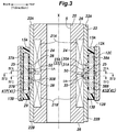
- FIG. 3 is a sectional view taken along line of FIG. 1 ;
- FIG. 4A is a sectional view taken along line IVA-IVA of FIG. 3 ;
- FIG. 4B is a sectional view taken along line IVB-IVB of FIG. 3 ;
- FIG. 4C is a sectional view taken along line IVC-IVC of FIG. 3 ;
- FIG. 5A is a vertical sectional view of the variable stiffness bushing assembly showing the magnetic flux produced from the coils of the variable stiffness bushing assembly;
- FIG. 5B is a cross sectional view of the variable stiffness bushing assembly showing the magnetic flux produced from the coils of the variable stiffness bushing assembly.
- FIG. 6 is a graph showing the relationship between the engine rotational speed and the cabin noise in a high stiffness condition (solid line) and a low stiffness condition (broken line).
- variable stiffness bushing assembly 1 according to a preferred embodiment of the present invention as applied to a wheel suspension device of a vehicle is described in the following with reference to the appended drawings.
- variable stiffness bushing assembly 1 of the present invention is provided on a lower arm 2 of the wheel suspension device consisting of a double wishbone type suspension device for connecting a knuckle (not shown in the drawings) that rotatably supports a rear wheel to the vehicle body.
- the variable stiffness bushing assembly 1 is provided at the vehicle body side end of the lower arm 2 .
- the lower arm 2 is a metal member extending in the lateral direction, and is connected to a knuckle at the outer end thereof.
- a through hole 3 is vertically passed through the inner end of the lower arm 2 , and the variable stiffness bushing assembly 1 having a generally cylindrical shape is fitted into the through hole 3 such that the axial line X (axial direction X) is directed in the vertical direction.
- the variable stiffness bushing assembly 1 is provided with a bolt hole 5 extending centrally along the axial line X, and a bolt is passed through the bolt hole 5 to be fastened to the vehicle body so that the inner end of the lower arm 2 is connected to the vehicle body via the variable stiffness bushing assembly 1 .
- the orientation of the variable stiffness bushing assembly 1 in this embodiment is only exemplary, and does not limit the scope of the present invention.
- the variable stiffness bushing assembly 1 includes a cylindrical inner tubular member 11 coaxially disposed in relation to the axial line X, and an outer tubular member 12 which is disposed coaxially with respect to and surrounds the inner tubular member 11 .
- an annular or a cylindrical gap is defined between the inner tubular member 11 and the outer tubular member 12 .
- the variable stiffness bushing assembly 1 further includes an elastic member 13 that is interposed between the inner tubular member 11 and the outer tubular member 12 , and connects the inner tubular member 11 and the outer tubular member 12 to each other.
- the inner tubular member 11 extends along the axial line X extending vertically.
- the inner tubular member 11 includes a substantially cylindrical inner yoke 20 that internally defines the bolt hole 5 , a pair of coils 21 wound around the inner yoke 20 in an axially spaced apart relationship, a pair of outer yokes 22 each connected to the inner yoke 20 at one end thereof located on an end part of the corresponding coil 21 remote from the other coil 21 , the other ends of the outer yokes 22 axially opposing each other, and an intermediate tubular member 23 surrounding the coils 21 and axially abutting against the mutually opposing ends of the outer yokes 22 .
- the intermediate tubular member 23 is axially interposed between the opposing axial ends of the outer yokes 22 .
- the inner yoke 20 and the outer yokes 22 are made of a magnetic material or a material having a high magnetic permeability such as iron based material.
- the inner yoke 20 includes a cylindrical inner yoke main body 24 extending along the axial line X, an annular large diameter portion 25 projecting radially outward from an axially central part of the inner yoke main body 24 , and a pair of annular flanges 26 projecting radially outward from either axial end of the inner yoke main body 24 .
- the annular flanges 26 have a same outer diameter which is slightly smaller than the outer diameter of the annular large diameter portion 25 .
- the coils 21 are formed by winding a coated copper wire around an upper part and a lower part of the inner tubular member 11 located on either axial side of the annular large diameter portion 25 in a substantially coaxial relationship.
- the upper coil 21 (which may be referred to as the upper coil 21 A) and the lower coil 21 (which may be referred to as the lower coil 21 B) have a same axial length and a same number of turns. Further, the winding direction of the upper coil 21 A and the winding direction of the lower coil 21 B are reversed from each other.
- the outer diameters of the upper coil 21 A and the lower coil 21 B are substantially equal to each other, and the outer peripheral surface of the upper coil 21 A and the outer peripheral surface of the lower coil 21 B are flush with the outer peripheral surfaces of the upper and lower annular flanges 26 .
- the upper coil 21 A is in contact with an annular shoulder surface defined by the annular large diameter portion 25 at the lower end, and is in contact with an annular shoulder surface defined by the upper annular flange 26 at the upper end.
- the lower coil 21 B is in contact with an annular shoulder surface defined by the annular large diameter portion 25 at the upper end, and is in contact with an annular shoulder surface defined by the lower annular flange 26 at the lower end.
- Each annular flange 26 is provided with a lead slot 27 which is recessed radially inward from the outer circumferential surface, and extends over the entire vertical length of the annular flange 26 .
- Lead wires of the copper wire of each coil 21 are passed axially through the corresponding lead slot 27 .
- the inner yoke 20 functions as an iron core that conducts the magnetic flux generated by the coils 21 when electric current is supplied thereto.
- the outer yokes 22 each have a cylindrical shape extending along the axial line X. As shown in FIG. 3 , each of the outer yokes 22 is press fitted onto the annular flange 26 on the corresponding axial side of the inner yoke 20 , and surrounds the corresponding coil 21 so that an axial end of the outer yoke 22 axially opposes the annular large diameter portion 25 of the inner yoke 20 . Thus, an annular gap SA, SB is defined between the annular large diameter portion 25 and the opposing axial end of each outer yoke 22 .
- the outer yoke 22 connected to the upper end of the inner yoke 20 may be referred to as an upper outer yoke 22 A, and the outer yoke 22 connected to the lower end of the inner yoke 20 may be referred to as a lower outer yoke 22 B.
- the upper outer yoke 22 A has an inner diameter substantially equal to the outer diameter of the upper annular flange 26 and the upper coil 21 A so that the upper annular flange 26 and the upper coil 21 A are snugly received in the upper outer yoke 22 A.
- the lower outer yoke 22 B likewise has an inner diameter substantially equal to the outer diameter of the lower annular flange 26 and the lower coil 21 B so that the lower annular flange 26 and the lower coil 21 B are snugly received in the lower outer yoke 22 B.
- the upper outer yoke 22 A and the lower outer yoke 22 B are made of a metal material having a high magnetic permeability or ferromagnetic material.
- the upper outer yoke 22 A and the lower outer yoke 22 B are made of iron based material.
- the lower end portion of the upper outer yoke 22 A and the upper end portion of the lower outer yoke 22 B are provided with cylindrical small diameter portions 28 , respectively, that protrude toward each other along the axial line X of the inner yoke 20 , each small diameter portion 28 having a smaller outer diameter than the remaining part of the outer yokes 22 .
- Each small diameter portion 28 defines an annular shoulder surface extending substantially orthogonally to the axial line X at the base end thereof.
- the intermediate tubular member 23 has a generally cylindrical shape, and is disposed axially between the upper outer yoke 22 A and the lower outer yoke 22 B.
- the inner yoke 20 extends through the inner bore of the intermediate tubular member 23 together with the upper and lower coils 21 , and the outer peripheral surface of the annular large diameter portion 25 contacts the inner peripheral surface of the intermediate tubular member 23 as shown in FIG. 3 .
- the intermediate tubular member 23 surrounds and covers the gap SA between the upper outer yoke 22 A and the annular large diameter portion 25 and the gap SB between the lower outer yoke 22 B and the annular large diameter portion 25 from the radially outer side.
- the intermediate tubular member 23 may be formed of a non-magnetic material (preferably, a non-magnetic metal) having a lower magnetic permeability than the metal forming the inner yoke 20 .
- the intermediate tubular member 23 is preferably made of aluminum.
- the intermediate tubular member 23 consists of a pair of tubular members 23 A and 23 B that are axially abutting each other. Since the lower tubular member 23 B is substantially identical in shape as the upper tubular member 23 A, only the upper tubular member 23 A will be described in the following in detail.
- the parts of the intermediate tubular member 23 may each be accompanied by a suffix A or B depending on which of the upper tubular member 23 A and the lower tubular member 23 B the particular part is associated with.
- the upper tubular member 23 A includes a cylindrical upper tubular member main body 30 A and a protruding portion 31 A protruding inward from the lower end of the inner peripheral surface of the upper tubular member main body 30 A and elongated in the circumferential direction.
- the inner diameter of the upper tubular member main body 30 A is substantially equal to the outer diameter of the small diameter portion 28 of the upper outer yoke 22 A.
- the small diameter portion 28 of the upper outer yoke 22 A is snugly fitted in the upper tubular member main body 30 A in such a manner that substantially no gap is defined between the outer peripheral surface of the small diameter portion 28 of the upper outer yoke 22 A and the inner peripheral surface of the upper tubular member main body 30 A.
- the upper end of the upper tubular member main body 30 A abuts against the shoulder surface 29 of the upper outer yoke 22 A.
- the lower end of the upper tubular member main body 30 A is positioned at a substantially central part with respect to the vertical direction of the annular large diameter portion 25 , and is connected to the upper end of the lower tubular member main body 30 B of the lower tubular member 23 B.
- the inner peripheral surface of the lower end of the upper tubular member main body 30 A is in contact with the outer peripheral surface of the annular large diameter portion 25 .
- the protruding portion 31 A has a cylindrical inner peripheral surface, and extends over a certain angular range when viewed from above as shown in FIG. 4A .
- the protruding portion 31 A protrudes from the lower end of the inner peripheral surface of the upper tubular member main body 30 A, and fills the gap SA defined between the lower end of the upper outer yoke 22 A (in particular, the small diameter portion 28 of the upper outer yoke 22 A) and the annular large diameter portion 25 .
- the lower surface of the protruding portion 31 A abuts against the upper surface of the annular large diameter portion 25 .
- the upper surface of the protruding portion 31 A is in contact with the lower surface of the small diameter portion 28 of the upper outer yoke 22 A.
- a first circumferential passage 33 is defined by the outer peripheral surface of the upper coil 21 A, the inner peripheral surface of the upper tubular member main body 30 A and the circumferential end surfaces of the protruding portion 31 A.
- the circumferential length of the first circumferential passage 33 may be between 1 ⁇ 2 and 3 ⁇ 4 of the full circle, or between the angular ranges of 180 degrees and 270 degrees.
- the upper tubular member main body 30 A is provided with a pair of first openings 32 A penetrating in the radial direction at the respective circumferential ends of the protruding portion 31 A so that the first circumferential passage 33 communicates with the radially outer side of the intermediate tubular member 23 via the first openings 32 A.
- each first opening 32 A is defined by a notch formed in the lower end of the upper tubular member main body 30 A, and the upper edge of the lower tubular member main body 30 B.
- the lower tubular member 23 B is vertically inverted, and rotated counterclockwise by 90 degrees as viewed from above with respect to the upper tubular member 23 A. Similarly as the upper tubular member 23 A, the small diameter portion 28 of the lower outer yoke 22 B is snugly fitted into the lower tubular member 23 B.
- the lower tubular member 23 B includes a cylindrical lower tubular member main body 30 B and a protruding portion 31 B protruding inward from the upper end of the inner peripheral surface of the lower tubular member main body 30 B and elongated in the circumferential direction.
- the protruding portion 31 B protrudes into the gap defined between the lower outer yoke 22 B and the annular large diameter portion 25 , and closes the gap SB defined between the lower outer yoke 22 B and the annular large diameter portion 25 .
- a second circumferential passage 35 is defined by the outer peripheral surface of the lower coil 21 B, the inner peripheral surface of the lower tubular member main body 30 B and the circumferential end surfaces of the protruding portion 31 B.
- the lower tubular member main body 30 B is provided with a pair of second openings 32 B penetrating in the radial direction at the respective circumferential ends of the protruding portion 31 B so that the second circumferential passage 35 communicates with the radially outer side of the intermediate tubular member 23 via the second openings 32 B.
- each second opening 32 B is defined by a notch formed in the upper end of the lower tubular member main body 30 B, and the lower edge of the upper tubular member main body 30 A.
- the first circumferential passage 33 and the second circumferential passage 35 are spaced apart from each other in the vertical direction.
- the first circumferential passage 33 is disposed radially outer side of the lower end of the upper coil 21 A
- the second circumferential passage 35 is disposed radially outer side of the upper end of the lower coil 21 B.
- the first circumferential passage 33 and the second circumferential passage 35 are passed between the annular large diameter portion 25 and the outer yoke 22 .
- the first circumferential passage 33 and the second circumferential passage 35 have a same shape, and the second circumferential passage 35 is located at a position rotated 90 degrees counterclockwise from the first circumferential passage 33 as viewed from above.
- the outer tubular member 12 includes an upper outer tubular member 12 A, a lower outer tubular member 12 B, and a housing member 12 C surrounding the upper outer tubular member 12 A and the lower outer tubular member 12 B.
- the upper outer tubular member 12 A and the lower outer tubular member 12 B have a substantially same shape, and are arranged around the axial line X of the inner tubular member 11 in a coaxial relationship to the inner tubular member 11 .
- the lower end of the upper outer tubular member 12 A and the upper end of the lower outer tubular member 12 B abut against each other.
- the housing member 12 C has a cylindrical shape arranged around the axial line X in a coaxial relationship to the inner tubular member 11 .
- the housing member 12 C has an inner bore extending vertically, and the upper outer tubular member 12 A and the lower outer tubular member 12 B are received in the inner bore.
- the outer peripheral surface of the upper outer tubular member 12 A and the outer peripheral surface of the lower outer tubular member 12 B are in close contact with the inner peripheral surface of the housing member 12 C, and the upper outer tubular member 12 A and the lower outer tubular member 12 B are integrally connected to the housing member 12 C.
- the inner diameter of the outer tubular member 12 (the inner diameter of the upper outer tubular member 12 A and the inner diameter of the lower outer tubular member 12 B) is larger than the outer diameter of the inner tubular member 11 , or more specifically, larger than the outer diameter of the outer yoke 22 so that a gap is formed between the inner tubular member 11 and the outer tubular member 12 .
- the elastic member 13 which is thus positioned in the gap defined between the inner tubular member 11 and the outer tubular member 12 is made of a material having elasticity, such as rubber or other polymer material.
- the elastic member 13 consists of an upper elastic member 13 A and a lower elastic member 13 B.
- the upper elastic member 13 A is a tubular member.
- the upper elastic member 13 A is in contact with the outer peripheral surface of the upper outer yoke 22 A and the upper tubular member 23 A at the entire inner peripheral surface thereof, and the inner peripheral surface of the upper outer tubular member 12 A at the entire outer peripheral surface thereof.
- the bottom surface of the upper elastic member 13 A is formed with a pair of first upper recesses 37 A and 38 A which are positioned diagonally opposite to each other about the axial line X and along a first direction Y orthogonal to the axial line X, and a pair of second upper recesses 39 A and 40 A which are positioned diagonally opposite to each other about the axial line X and along a second direction Z orthogonal to both the axial line X and the first direction Y.
- the first upper recesses 37 A and 38 A and the second upper recesses 39 A and 40 A are each recessed upward, and extend along the circumferential direction by a same angle which is slightly smaller than 90 degrees.
- the lower elastic member 13 B is also a tubular member similar to the upper elastic member 13 A, and is in contact with the outer peripheral surface of the lower outer yoke 22 B and the lower tubular member 23 B at the entire inner peripheral surface thereof.
- the lower elastic member 13 B is also in contact with the inner circumferential surface of the lower outer tubular member 12 B at the entire outer circumferential surface thereof.
- the upper surface of the lower elastic member 13 B is formed with a pair of first lower recesses 37 B and 38 B that are recessed downward at positions aligning with the first upper recesses 37 A and 38 A, respectively, and a pair of second lower recesses 39 B, 40 B that are recessed downward at positions aligning with the second upper recesses 39 A and 40 A.
- first upper recesses 37 A and 38 A and the first lower recesses 37 B and 38 B jointly define a pair of first liquid chambers 41 P and 41 Q, respectively, extending along the axial line X and opposing each other in the first direction Y.
- first liquid chambers 41 P and 41 Q may be collectively referred to as “the first liquid chambers 41 ”.
- second upper recesses 39 A and 40 A and the second lower recesses 39 B and 40 B jointly define a pair of second liquid chambers 42 P and 42 Q, respectively, extending along the axial line X and opposing each other in the second direction Z.
- the second liquid chambers 42 P and 42 Q may be collectively referred to as “the second liquid chambers 42 ”.
- the first openings 32 A or the circumferential end portions of the first communication passage 47 are located radially inward of the first liquid chambers 41 , and the elastic member 13 is provided with a pair of communication openings 44 communicating the first communication passage 47 to the respective first liquid chambers 41 via the first openings 32 A, respectively.
- the second openings 32 B or the circumferential end portions of the second communication passage 49 are located radially inward of the second liquid chambers 42 , and the elastic member 13 is provided with a pair of communication openings 44 communicating the second communication passage 49 to the respective second liquid chambers 42 via the second openings 32 B, respectively.
- the first liquid chambers 41 communicate with each other via the first communication passage 47 including the first circumferential passage 33 , the two first openings 32 A, and the communication openings 44 .
- the second liquid chambers 42 communicate with each other via the second communication passage 49 including the second circumferential passage 35 , the two second openings 32 B, and the communication openings 44 .
- variable stiffness bushing assembly 1 is mounted to the lower arm 2 such that the first direction Y coincides with the fore and aft direction, and the second direction Z coincides with the lateral direction when the steering angle is zero to be exact.
- the magnetic fluid 50 is contained in the first liquid chambers 41 , the second liquid chambers 42 , the first communication passage 47 , and the second communication passage 49 .
- the magnetic fluid 50 may be an incompressible fluid containing iron particles dispersed in a solvent such as oil, and in particular, may consist of a fluid whose viscoelasticity, particularly viscosity changes depending on the intensity of the magnetic field applied thereto such as a magnetic viscoelastic fluid (MRF: Magnetorheological Fluid) and a magnetic viscoelastic compound (MRC: Magnetorheological Compound).
- MRF Magnetorheological Fluid
- MRC Magnetorheological Compound
- the fine particles of iron are arranged in chains extending along the direction of the magnetic field to form chain clusters.
- the flow of the solvent in the direction perpendicular to the magnetic field is hindered by the chain clusters, and the effective viscosity of the magnetic fluid 50 increases.
- the magnetic fluid 50 may even become almost solid.
- the upper coil 21 A and the lower coil 21 B are connected to different voltage sources 60 A and 60 B, respectively, and the voltage sources 60 A and 60 B are connected to a control unit 65 via signal lines.
- a control unit 65 is connected to onboard sensors 80 such as a steering angle sensor and an acceleration sensor.
- variable stiffness bushing assembly 1 The mode of operation of the variable stiffness bushing assembly 1 according to this embodiment is discussed in the following.
- a load parallel to the first direction Y is applied to the variable stiffness bushing assembly 1 , the elastic member 13 is deformed in such a manner that the volume of one of the first liquid chambers 41 increases, and the volume of the other first liquid chamber 41 decreases by a corresponding amount.
- the magnetic fluid 50 flows from one of the first liquid chambers 41 to the other first liquid chamber 41 via the first communication passage 47 .
- the magnetic fluid 50 encounters resistance when flowing through the first communication passage 47 so that a damping force against the deformation in the Y direction is created by the variable stiffness bushing assembly 1 .
- the elastic member 13 is deformed in such a manner that the volume of one of the second liquid chambers 42 increases, and the volume of the other second liquid chamber 42 decreases by a corresponding amount.
- the magnetic fluid 50 flows from one of the second liquid chambers 42 to the other second liquid chamber 42 via the second communication passage 49 .
- the magnetic fluid 50 encounters resistance when flowing through the second communication passage 49 so that a damping force against the deformation in the Z direction is created by the variable stiffness bushing assembly 1 .
- FIGS. 5A and 5B show the magnetic field lines in solid lines when an equal voltage is applied to the upper coil 21 A and the lower coil 21 B to create mutually opposing magnetic fields.
- the upper coil 21 A and the lower coil 21 B form respective magnetic circuits 70 A and 70 B. More specifically, the magnetic circuit 70 A formed by the upper coil 21 A generates a loop of magnetic flux that passes through the annular large diameter portion 25 , the upper portion of the inner yoke main body 24 , the upper annular flange 26 , and the upper outer yoke 22 A. At this time, the magnetic flux generated by the upper coil 21 A in large part passes through the gap between the upper outer yoke 22 A and the annular large diameter portion 25 .
- the magnetic circuit 70 A of the upper coil 21 A functions so as to concentrate the magnetic field generated by the upper coil 21 A in the gap between the upper outer yoke 22 A and the annular large diameter portion 25 .
- the magnetic field generated by the upper coil 21 A is effectively applied to the first communication passage 47 .
- the viscosity of the magnetic fluid 50 contained in the first communication passage 47 increases, and the movement of the magnetic fluid 50 between the first liquid chambers 41 is hindered in such a manner that the deformation of the variable stiffness bushing assembly 1 is restricted when a load directed in the first direction Y is applied to the variable stiffness bushing assembly 1 , and the stiffness of the variable stiffness bushing assembly 1 increases.
- the magnetic circuit 70 B formed by the lower coil 21 B generates a loop of magnetic flux that passes through the annular large diameter portion 25 , the lower portion of the inner yoke main body 24 , the lower annular flange 26 , and the lower outer yoke 22 B.
- the magnetic flux generated by the lower coil 21 B in large part passes through the gap between the lower outer yoke 22 B and the annular large diameter portion 25 . Therefore, the magnetic circuit 70 B of the lower coil 21 B functions so as to concentrate the magnetic field generated by the lower coil 21 B in the gap between the lower outer yoke 22 B and the annular large diameter portion 25 .
- the magnetic field generated by the lower coil 21 B is effectively applied to the second communication passage 49 .
- the viscosity of the magnetic fluid 50 contained in the second communication passage 49 increases, and the movement of the magnetic fluid 50 between the second liquid chambers 42 is hindered in such a manner that the deformation of the variable stiffness bushing assembly 1 is restricted when a load directed in the second direction Z is applied to the variable stiffness bushing assembly 1 , and the stiffness of the variable stiffness bushing assembly 1 increases.
- variable stiffness bushing assembly 1 When the current flowing through the upper coil 21 A is made larger than the current flowing through the lower coil 21 B by controlling the output voltages of the voltage sources 60 A and 60 B, the magnetic field applied to the first communication passage 47 gets larger than the magnetic field applied to the second communication passage 49 . As a result, the stiffness in the first direction Y of the variable stiffness bushing assembly 1 can be more increased than the stiffness in the second direction Z. Similarly, when the current flowing through the lower coil 21 B is increased, the magnetic field applied to the second communication passage 49 becomes larger than the magnetic field applied to the first communication passage 47 so that the stiffness of the variable stiffness bushing assembly 1 in the second direction Z is more increased than in the first direction Y.
- variable stiffness bushing assembly 1 by controlling the magnitude of the current flowing in the upper coil 21 A and the magnitude of the current flowing in the lower coil 21 B, the stiffness in the two directions of orthogonal to the axial direction X (the first direction Y and the second direction) of the variable stiffness bushing assembly 1 can be individually controlled.
- control unit 65 increases the stiffness in the fore and aft direction (or in the first direction Y) by controlling the voltage output from the voltage source 60 A so as to increase the current flowing through the upper coil 21 A.
- the vehicle body When the vehicle corners at a high speed, the vehicle body may tilt outward in the turning direction due to the centrifugal force caused by the cornering. As a result, the downward force of the wheel located on the outer side with respect to the cornering direction is increased, and the lateral force directed toward the laterally inner side acts on the wheel with respect to the cornering direction.
- the control unit 65 controls the voltage output from the voltage source 60 B to increase the current flowing in the lower coil 21 B so that the stiffness of the variable stiffness bushing assembly 1 in the lateral direction (or in the second direction Z) is increased. As a result, the wheel is prevented from being excessively displaced relative to the vehicle body so that the handling of the vehicle can be improved.
- FIG. 6 shows the engine speed dependency of the noise intensity (in decibels) transmitted to the passenger compartment when the stiffness is increased (solid line) and when the stiffness is decreased (broken line).
- the vibration can be absorbed by the variable stiffness bushing assembly 1 , and the noise intensity in the passenger compartment can be reduced.
- variable stiffness bushing assembly 1 when the handling of the vehicle is desired to be improved, the stiffness of the variable stiffness bushing assembly 1 can be increased along the direction in which the load is applied. Conversely, when the vibration and noise are desired to be reduced, the stiffness of the variable stiffness bushing assembly 1 can be reduced so that the transmission of vibration and noise to the passenger compartment may be reduced.
- the coil 21 consisting of a solenoid coil generally generates a strong magnetic field inside the inner bore thereof owing to the current flowing through the coil 21 . Therefore, in the variable stiffness bushing assembly 1 in which the stiffness is made variable by using the magnetic fluid 50 , it is preferable to provide a flow passage of the magnetic fluid 50 in the inner bore of the coil 21 where the strong magnetic field is generated. However, it is impractical in most cases to provide the flow passage of the magnetic fluid 50 in the inner bore of the coil 21 .
- the direction of the magnetic field generated in the upper coil 21 A and the direction of the magnetic field generated in the lower coil 21 B are opposite to each other.
- the magnetic field lines from the upper coil 21 A and the magnetic field lines from the lower coil 21 B extend radially outward and away from each other as shown in FIG. 5B .
- the magnetic field lines extend through the gap between the upper coil 21 A and the lower coil 21 B in radially outward direction, and vertically upward and downward directions, respectively.
- the cross sectional area of the flow passage of the magnetic fluid 50 is preferable to reduce the cross sectional area of the flow passage of the magnetic fluid 50 and increase the length of the flow passage of the magnetic fluid 50 .
- the first liquid chambers 41 are positioned diagonally apart from each other along the circumferential direction, and so are the second liquid chambers 42 , the first communication passage 47 and the second communication passage 49 connecting them are elongated in the circumferential direction. Therefore, between the first liquid chambers 41 and between the second liquid chambers 42 , the movement of the fluid is strongly affected by the magnetic field so that the variable range of the stiffness of the variable stiffness bushing assembly 1 can be maximized.
- the gaps SA and SB between the annular large diameter portion 25 and the outer yoke 22 are respectively filled by the protruding portions 31 of the intermediate tubular member 23 so that the first circumferential passage 33 and the second circumferential passage 35 extend circumferentially in an arcuate manner. If the protruding portions 31 were absent, the gap between the annular large diameter portion 25 and the outer yoke 22 would be fully annular, and the first liquid chambers 41 and the second liquid chambers 42 would be commonly communicated with one another via a pair of arcuate passages connected in parallel to each other.
- the intermediate tubular member 23 is disposed between the two outer yokes 22 , and the intermediate tubular member 23 fills the gap SA and the gap SB from the radially outer direction so as to define the first communication passage 47 and the second communication passage 48 in an arcuate shape.
- the intermediate tubular member 23 is formed of a material having a low magnetic permeability, the magnetic circuits 70 A and 70 B are not disturbed by the presence of the intermediate tubular member 23 between the outer yokes 22 , and a magnetic field can be applied to the first communication passage 47 and the second communication passage 48 in a favorable manner as shown in FIG. 5 .
Landscapes
- Engineering & Computer Science (AREA)
- General Engineering & Computer Science (AREA)
- Mechanical Engineering (AREA)
- Physics & Mathematics (AREA)
- Electromagnetism (AREA)
- Vehicle Body Suspensions (AREA)
- Combined Devices Of Dampers And Springs (AREA)
- Fluid-Damping Devices (AREA)
Abstract
Description
Claims (5)
Applications Claiming Priority (3)
| Application Number | Priority Date | Filing Date | Title |
|---|---|---|---|
| JPJP2019-025089 | 2019-02-15 | ||
| JP2019025089A JP7042227B2 (en) | 2019-02-15 | 2019-02-15 | Variable stiffness bush |
| JP2019025089 | 2019-02-15 |
Publications (2)
| Publication Number | Publication Date |
|---|---|
| US20200263751A1 US20200263751A1 (en) | 2020-08-20 |
| US11215253B2 true US11215253B2 (en) | 2022-01-04 |
Family
ID=72041928
Family Applications (1)
| Application Number | Title | Priority Date | Filing Date |
|---|---|---|---|
| US16/787,683 Active 2040-04-16 US11215253B2 (en) | 2019-02-15 | 2020-02-11 | Variable stiffness bushing assembly |
Country Status (3)
| Country | Link |
|---|---|
| US (1) | US11215253B2 (en) |
| JP (1) | JP7042227B2 (en) |
| CN (1) | CN111577813B (en) |
Cited By (1)
| Publication number | Priority date | Publication date | Assignee | Title |
|---|---|---|---|---|
| US20220299085A1 (en) * | 2021-03-16 | 2022-09-22 | Honda Motor Co., Ltd. | Mount bush |
Families Citing this family (12)
| Publication number | Priority date | Publication date | Assignee | Title |
|---|---|---|---|---|
| US11673445B2 (en) * | 2019-07-30 | 2023-06-13 | Continental Automotive Systems, Inc. | Powertrain proactive damping system using magneto rheological materials |
| KR102767246B1 (en) * | 2019-11-08 | 2025-02-12 | 현대자동차주식회사 | Void bush for vehicle suspension |
| CN112461304B (en) * | 2020-11-09 | 2024-04-19 | 江苏威尔胜电子科技有限公司 | Venturi tube with changeable throat section |
| JP7116437B2 (en) * | 2020-12-22 | 2022-08-10 | 本田技研工業株式会社 | suspension arm bush |
| US11485187B1 (en) * | 2021-05-28 | 2022-11-01 | Zoox, Inc. | Configurable bushing |
| US11807065B1 (en) * | 2021-05-28 | 2023-11-07 | Zoox, Inc. | Pivot offset elasto-hydraulic bushing |
| JP2023013310A (en) | 2021-07-15 | 2023-01-26 | 住友理工株式会社 | Fluid sealed type cylindrical vibration control device |
| JP7724734B2 (en) * | 2022-03-04 | 2025-08-18 | 住友理工株式会社 | Fluid-filled vibration isolation device |
| CN114776747B (en) * | 2022-03-15 | 2023-09-22 | 东北大学 | Composite hyperbolic corrugated sandwich structure used to suppress vibration of aircraft engine oil tanks and its application |
| CN115013467B (en) * | 2022-04-19 | 2023-10-24 | 大连海事大学 | Spherical magneto-rheological damper |
| CN115654030B (en) * | 2022-05-31 | 2025-10-17 | 四川建安工业有限责任公司 | Axial torque converter |
| CN116123239A (en) * | 2022-12-30 | 2023-05-16 | 福沃克汽车技术(苏州)有限公司 | Magnetorheological elastomer bushing for auxiliary frame of automobile |
Citations (16)
| Publication number | Priority date | Publication date | Assignee | Title |
|---|---|---|---|---|
| JPS61205503A (en) | 1985-03-07 | 1986-09-11 | Tokai Rubber Ind Ltd | Upper support built-up body for car suspension |
| JPS63176844A (en) | 1986-09-16 | 1988-07-21 | Bridgestone Corp | Vibration-proof bush |
| JPH023721A (en) | 1987-10-12 | 1990-01-09 | Toyota Motor Corp | Bush having variable characteristic |
| US5460585A (en) * | 1994-03-11 | 1995-10-24 | B.G.M. Engineering, Inc. | Muscle training and physical rehabilitation machine using electro-rheological magnetic fluid |
| JPH07280024A (en) | 1994-04-06 | 1995-10-27 | Bridgestone Corp | Vibration proof device |
| EP0784163A1 (en) | 1996-01-11 | 1997-07-16 | Ford Motor Company Limited | Variable stiffness bushing using magnetorheological elastomers |
| US5816587A (en) * | 1996-07-23 | 1998-10-06 | Ford Global Technologies, Inc. | Method and apparatus for reducing brake shudder |
| KR20030013719A (en) | 2001-08-09 | 2003-02-15 | 현대자동차주식회사 | Hydraulic suspension bush |
| JP2005249022A (en) | 2004-03-03 | 2005-09-15 | Honda Motor Co Ltd | Suspension bush |
| EP1705400A1 (en) | 2005-03-23 | 2006-09-27 | Hutchinson | Vibration damping device containing a variable viscosity fluid, system comprising such a device and vehicle comprising such a system |
| CN101253347A (en) | 2005-09-01 | 2008-08-27 | 普尔曼公司 | hydraulic bushing |
| CN103668869A (en) | 2012-08-31 | 2014-03-26 | 株式会社东芝 | Washing machine damper |
| CN104191927A (en) | 2014-09-12 | 2014-12-10 | 东风小康汽车有限公司重庆分公司 | Axial variable-damping hydraulic bushing for automotive suspension |
| US9835218B2 (en) * | 2015-05-12 | 2017-12-05 | Honda Motor Co., Ltd. | Vehicle active damper |
| US20180066723A1 (en) * | 2015-03-16 | 2018-03-08 | Honda Motor Co., Ltd. | Dynamic damper, vibration isolator, and method for manufacturing magnetic viscous elastomer |
| US20200263730A1 (en) * | 2019-02-15 | 2020-08-20 | Honda Motor Co., Ltd. | Variable stiffness bushing assembly |
Family Cites Families (6)
| Publication number | Priority date | Publication date | Assignee | Title |
|---|---|---|---|---|
| JPS60168931A (en) * | 1984-02-08 | 1985-09-02 | Nissan Motor Co Ltd | Vibration isolator encapsulated with fluid |
| JPS61274131A (en) * | 1985-05-30 | 1986-12-04 | Tokai Rubber Ind Ltd | Fluid charged type bushing assembly |
| JPS6439944U (en) * | 1987-09-07 | 1989-03-09 | ||
| JPH023722A (en) * | 1987-10-12 | 1990-01-09 | Toyota Motor Corp | Bush having variable characteristic |
| JPH0375337U (en) * | 1989-11-27 | 1991-07-29 | ||
| EP1350972A3 (en) * | 2002-04-04 | 2004-06-23 | Dana Corporation | Cardan shaft center bearing assembly including a support member containing a rheological fluid |
-
2019
- 2019-02-15 JP JP2019025089A patent/JP7042227B2/en active Active
-
2020
- 2020-02-07 CN CN202010082590.2A patent/CN111577813B/en active Active
- 2020-02-11 US US16/787,683 patent/US11215253B2/en active Active
Patent Citations (17)
| Publication number | Priority date | Publication date | Assignee | Title |
|---|---|---|---|---|
| JPS61205503A (en) | 1985-03-07 | 1986-09-11 | Tokai Rubber Ind Ltd | Upper support built-up body for car suspension |
| JPS63176844A (en) | 1986-09-16 | 1988-07-21 | Bridgestone Corp | Vibration-proof bush |
| US5050850A (en) | 1986-09-16 | 1991-09-24 | Bridgestone Corporation | Electrorheological anti-vibration bush |
| JPH023721A (en) | 1987-10-12 | 1990-01-09 | Toyota Motor Corp | Bush having variable characteristic |
| US5460585A (en) * | 1994-03-11 | 1995-10-24 | B.G.M. Engineering, Inc. | Muscle training and physical rehabilitation machine using electro-rheological magnetic fluid |
| JPH07280024A (en) | 1994-04-06 | 1995-10-27 | Bridgestone Corp | Vibration proof device |
| EP0784163A1 (en) | 1996-01-11 | 1997-07-16 | Ford Motor Company Limited | Variable stiffness bushing using magnetorheological elastomers |
| US5816587A (en) * | 1996-07-23 | 1998-10-06 | Ford Global Technologies, Inc. | Method and apparatus for reducing brake shudder |
| KR20030013719A (en) | 2001-08-09 | 2003-02-15 | 현대자동차주식회사 | Hydraulic suspension bush |
| JP2005249022A (en) | 2004-03-03 | 2005-09-15 | Honda Motor Co Ltd | Suspension bush |
| EP1705400A1 (en) | 2005-03-23 | 2006-09-27 | Hutchinson | Vibration damping device containing a variable viscosity fluid, system comprising such a device and vehicle comprising such a system |
| CN101253347A (en) | 2005-09-01 | 2008-08-27 | 普尔曼公司 | hydraulic bushing |
| CN103668869A (en) | 2012-08-31 | 2014-03-26 | 株式会社东芝 | Washing machine damper |
| CN104191927A (en) | 2014-09-12 | 2014-12-10 | 东风小康汽车有限公司重庆分公司 | Axial variable-damping hydraulic bushing for automotive suspension |
| US20180066723A1 (en) * | 2015-03-16 | 2018-03-08 | Honda Motor Co., Ltd. | Dynamic damper, vibration isolator, and method for manufacturing magnetic viscous elastomer |
| US9835218B2 (en) * | 2015-05-12 | 2017-12-05 | Honda Motor Co., Ltd. | Vehicle active damper |
| US20200263730A1 (en) * | 2019-02-15 | 2020-08-20 | Honda Motor Co., Ltd. | Variable stiffness bushing assembly |
Non-Patent Citations (1)
| Title |
|---|
| First Notification of Office Action for Application CN 202010082590.2 dated May 7, 2021; 20 pp. |
Cited By (2)
| Publication number | Priority date | Publication date | Assignee | Title |
|---|---|---|---|---|
| US20220299085A1 (en) * | 2021-03-16 | 2022-09-22 | Honda Motor Co., Ltd. | Mount bush |
| US11761511B2 (en) * | 2021-03-16 | 2023-09-19 | Honda Motor Co., Ltd. | Mount bush |
Also Published As
| Publication number | Publication date |
|---|---|
| JP7042227B2 (en) | 2022-03-25 |
| JP2020133700A (en) | 2020-08-31 |
| CN111577813A (en) | 2020-08-25 |
| CN111577813B (en) | 2022-04-01 |
| US20200263751A1 (en) | 2020-08-20 |
Similar Documents
| Publication | Publication Date | Title |
|---|---|---|
| US11215253B2 (en) | Variable stiffness bushing assembly | |
| US11441635B2 (en) | Liquid filled bushing assembly | |
| US11193532B2 (en) | Variable stiffness bushing | |
| EP2055985B1 (en) | Magneto-rheological damper | |
| US7958979B2 (en) | Variable damper | |
| JP7066647B2 (en) | Variable stiffness bush | |
| US20200263730A1 (en) | Variable stiffness bushing assembly | |
| US10767722B2 (en) | Mount for subframe | |
| US11221052B2 (en) | Mount bush | |
| US20200269672A1 (en) | Variable stiffness vibration damping device | |
| JP4654236B2 (en) | Variable damping force damper | |
| US11215261B2 (en) | Variable stiffness vibration damping device | |
| CN114658781A (en) | Suspension arm bushing | |
| US12515510B2 (en) | Vibration damping device | |
| JPS6346296B2 (en) | ||
| JP4913006B2 (en) | Variable damping force damper | |
| US20250290555A1 (en) | Active vibration damping device and method of manufacturing the same | |
| CN217502421U (en) | Combined structure of variable-rigidity bushing | |
| JP2023161998A (en) | Vibration isolator | |
| KR20050060830A (en) | Shock absorber structure to adjust a damping force for a suspension | |
| KR102706265B1 (en) | Suspension device for vehicle | |
| JPS61108006A (en) | fluid filled bush |
Legal Events
| Date | Code | Title | Description |
|---|---|---|---|
| AS | Assignment |
Owner name: HONDA MOTOR CO., LTD., JAPAN Free format text: ASSIGNMENT OF ASSIGNORS INTEREST;ASSIGNORS:ITO, YUHO;INOUE, TOSHIO;REEL/FRAME:051786/0242 Effective date: 20200206 |
|
| FEPP | Fee payment procedure |
Free format text: ENTITY STATUS SET TO UNDISCOUNTED (ORIGINAL EVENT CODE: BIG.); ENTITY STATUS OF PATENT OWNER: LARGE ENTITY |
|
| STPP | Information on status: patent application and granting procedure in general |
Free format text: APPLICATION DISPATCHED FROM PREEXAM, NOT YET DOCKETED |
|
| STPP | Information on status: patent application and granting procedure in general |
Free format text: DOCKETED NEW CASE - READY FOR EXAMINATION |
|
| STPP | Information on status: patent application and granting procedure in general |
Free format text: NON FINAL ACTION MAILED |
|
| STPP | Information on status: patent application and granting procedure in general |
Free format text: RESPONSE TO NON-FINAL OFFICE ACTION ENTERED AND FORWARDED TO EXAMINER |
|
| STPP | Information on status: patent application and granting procedure in general |
Free format text: NOTICE OF ALLOWANCE MAILED -- APPLICATION RECEIVED IN OFFICE OF PUBLICATIONS |
|
| STPP | Information on status: patent application and granting procedure in general |
Free format text: PUBLICATIONS -- ISSUE FEE PAYMENT RECEIVED |
|
| STPP | Information on status: patent application and granting procedure in general |
Free format text: PUBLICATIONS -- ISSUE FEE PAYMENT VERIFIED |
|
| STCF | Information on status: patent grant |
Free format text: PATENTED CASE |
|
| MAFP | Maintenance fee payment |
Free format text: PAYMENT OF MAINTENANCE FEE, 4TH YEAR, LARGE ENTITY (ORIGINAL EVENT CODE: M1551); ENTITY STATUS OF PATENT OWNER: LARGE ENTITY Year of fee payment: 4 |