JP4913006B2 - Variable damping force damper - Google Patents
Variable damping force damper Download PDFInfo
- Publication number
- JP4913006B2 JP4913006B2 JP2007261694A JP2007261694A JP4913006B2 JP 4913006 B2 JP4913006 B2 JP 4913006B2 JP 2007261694 A JP2007261694 A JP 2007261694A JP 2007261694 A JP2007261694 A JP 2007261694A JP 4913006 B2 JP4913006 B2 JP 4913006B2
- Authority
- JP
- Japan
- Prior art keywords
- yoke
- damping force
- magnetic field
- divided
- piston
- Prior art date
- Legal status (The legal status is an assumption and is not a legal conclusion. Google has not performed a legal analysis and makes no representation as to the accuracy of the status listed.)
- Expired - Fee Related
Links
Images


Landscapes
- Fluid-Damping Devices (AREA)
Description
本発明は、磁性流体または磁気粘性流体を作動流体として用いた減衰力可変ダンパに係り、詳しくは、減衰力可変範囲の増大等を実現する技術に関する。 The present invention relates to a damping force variable damper using a magnetic fluid or a magnetorheological fluid as a working fluid, and more particularly to a technique for realizing an increase in a damping force variable range.
近年、自動車のサスペンションに用いられる筒型ダンパでは、乗り心地や操縦安定性の向上を図るべく、減衰力の可変制御が可能な減衰力可変ダンパが種々開発されている。減衰力可変ダンパとしては、オリフィス面積を変化させるロータリバルブをピストンに設け、このロータリバルブをアクチュエータによって回転駆動する機械式のものが主流であったが、構成の簡素化や応答性の向上等を実現すべく、磁気粘性流体を作動流体として用い、ピストンと一体に形成された磁界生成手段(コイル)によって磁気粘性流体の粘度(すなわち、減衰力)を可変制御するものが出現している(特許文献1参照)。 2. Description of the Related Art In recent years, various types of damping force variable dampers capable of variable damping force control have been developed for cylindrical dampers used in automobile suspensions in order to improve riding comfort and steering stability. As the damping force variable damper, a mechanical type in which a rotary valve that changes the orifice area is provided on the piston and this rotary valve is driven to rotate by an actuator has been the mainstream, but simplification of the configuration and improvement of responsiveness etc. In order to achieve this, there has been a technology that uses a magnetorheological fluid as a working fluid and variably controls the viscosity (ie, damping force) of the magnetorheological fluid by means of a magnetic field generating means (coil) formed integrally with the piston (patent) Reference 1).
特許文献1の減衰力可変ダンパでは、ピストンが、外周にコイルが巻き回された円柱状のインナヨークと、インナヨークの両端に配置された一対のエンドプレートと、インナヨークと両エンドプレートを収容する円筒状のアウタヨークとから主に構成されている。インナヨークおよびアウタヨークはともに磁性体を素材としており、エンドプレートによって保持されることによって両者の間に環状流路が形成される。エンドプレートは、非磁性体を素材とした円盤状のものであり、環状流路に連通する複数の円弧状孔と、インナヨーク端部の凸部が係合する環状凹部と、ピストンロッド固定用のリングが係合する環状溝とを有している。また、インナヨークおよびエンドプレートは、アウタヨークの両端外縁を加締めることによって固定されている。減衰力制御装置は、コイルに供給する駆動電流を変化させることによって環状流路を流通する磁気粘性流体の粘度を増減させ、磁気粘性流体の流通抵抗(すなわち、減衰力)を可変制御する。
特許文献1の減衰力可変ダンパでは、磁界印加手段に供給する駆動電流を変化させることによって減衰力を可変制御する都合上、減衰力の可変範囲をあまり大きくすることができなかった。すなわち、この種の減衰力可変ダンパで高い減衰力を得るためにはコイルに大きな駆動電流を供給する必要があるが、この方法は電力消費や給電回路の負荷が増大すること等を考えると現実的ではなかった。また、減衰力の最大値を高めるには環状流路の流路面積を小さく方法も採り得るが、この場合には減衰力の最小値も高くなり、悪路走行時等における乗り心地が低下することになる。 In the damping force variable damper of Patent Document 1, the variable range of the damping force cannot be increased so much because the damping force is variably controlled by changing the drive current supplied to the magnetic field applying means. That is, in order to obtain a high damping force with this type of damping force variable damper, it is necessary to supply a large drive current to the coil. However, this method is a reality in view of increasing power consumption and the load on the power feeding circuit. It was not right. In order to increase the maximum damping force, it is possible to reduce the area of the annular channel. However, in this case, the minimum damping force is also increased, and the riding comfort on rough roads is reduced. It will be.
本発明は、このような背景に鑑みなされたもので、減衰力可変範囲の増大等を実現した減衰力可変ダンパを提供することを目的とする。 The present invention has been made in view of such a background, and an object thereof is to provide a damping force variable damper that realizes an increase in the damping force variable range and the like.
第1の発明は、磁性流体または磁気粘性流体が充填されるとともに車体側部材と車輪側部材とのどちらか一方に連結されたシリンダと、前記シリンダを一側液室と他側液室とに区画するとともに前記磁性流体または磁気粘性流体を当該一側液室と他側液室との間で流通させる環状流路が形成されたピストンと、前記車体側部材と車輪側部材とのどちらか他方を当該ピストンに連結するピストンロッドとを有し、前記環状流路を通過する前記磁性流体または前記磁気粘性流体に磁界を印加することで減衰力が制御される減衰力可変式ダンパであって、前記ピストンは、周方向に隣接する複数の分割ヨークから構成された円筒状のアウタヨークと、前記アウタヨークを拡径状態に保持する保持手段と、前記アウタヨークの内周面に対して所定の間隙をもって設置され、当該アウタヨークとの間に前記環状流路を画成するインナヨークと、前記インナヨークに保持され、前記磁界の形成に供される磁界印加手段とを備え、前記分割ヨークが磁性体を素材とし、前記磁界印加手段が磁界を形成していないときには前記分割ヨークから構成されたアウタヨークが前記保持手段によって拡径状態に保持される一方、前記磁界印加手段が磁界を形成したときに前記分割ヨークが当該磁界によって前記インナヨーク側に引き寄せられることを特徴とする。 According to a first aspect of the present invention, there is provided a cylinder filled with a magnetic fluid or a magnetorheological fluid and connected to one of a vehicle body side member and a wheel side member, and the cylinder into one side liquid chamber and another side liquid chamber. A piston having an annular flow path for partitioning and flowing the magnetic fluid or magnetorheological fluid between the one-side liquid chamber and the other-side liquid chamber; and the other of the vehicle body side member and the wheel side member A damping rod with a variable damping force, the damping force of which is controlled by applying a magnetic field to the magnetic fluid or the magnetorheological fluid passing through the annular flow path. The piston includes a cylindrical outer yoke composed of a plurality of circumferentially adjacent divided yokes, holding means for holding the outer yoke in an expanded state, and a predetermined interval with respect to the inner peripheral surface of the outer yoke. An inner yoke that defines the annular flow path between the outer yoke and a magnetic field applying unit that is held by the inner yoke and serves to form the magnetic field, and the divided yoke is made of a magnetic material. When the magnetic field applying means does not form a magnetic field, the outer yoke constituted by the divided yoke is held in an expanded state by the holding means, while when the magnetic field applying means forms a magnetic field, the divided yoke The yoke is attracted to the inner yoke side by the magnetic field .
また、第2の発明は、第1の発明に係る減衰力可変ダンパにおいて、前記保持手段は、前記分割ヨークと一体に形成され、隣接する分割ヨークの連結に供される連結片であることを特徴とする。 According to a second aspect of the present invention, in the damping force variable damper according to the first aspect of the present invention, the holding means is a connecting piece that is formed integrally with the divided yoke and is used to connect adjacent divided yokes. Features.
また、第3の発明は、第1の発明に係る減衰力可変ダンパにおいて、前記保持手段は、その両端が前記分割ヨークにそれぞれ固着または係合され、隣接する分割ヨークの連結に供される弾性連結部材であることを特徴とする。 According to a third aspect of the present invention, in the damping force variable damper according to the first aspect of the present invention, the holding means is elastically provided to connect adjacent divided yokes with both ends thereof fixed or engaged with the divided yokes. It is a connecting member.
第1の発明に係る減衰力可変ダンパによれば、磁界印加手段によって強い磁界が形成されると、磁性流体や磁気粘性流体の粘度が上昇すると同時に、分割ヨークが保持手段の保持力にうちかってインナヨーク側に磁力吸引されることで環状流路の流路面積が減少し、従来の減衰力可変ダンパに較べて減衰力が有意に増大する。また、第2の発明に係る減衰力可変ダンパによれば、保持手段を分割ヨークと一体に形成したため、構成部品点数や組立工数が低減できる。また、第3の発明に係る減衰力可変ダンパによれば、分割ヨークの素材として弾性に乏しいものを採用しても、分割ヨークに対する拡径状態の保持を効果的かつ高い耐久性をもって行える。 According to the damping force variable damper according to the first aspect of the present invention, when a strong magnetic field is formed by the magnetic field applying means, the viscosity of the magnetic fluid or magnetorheological fluid increases, and at the same time, the split yoke is exposed to the holding force of the holding means. By attracting magnetic force to the inner yoke side, the flow passage area of the annular flow passage is reduced, and the damping force is significantly increased as compared with the conventional damping force variable damper. Moreover, according to the damping force variable damper which concerns on 2nd invention, since the holding means was integrally formed with the division | segmentation yoke, the number of components and an assembly man-hour can be reduced. Further, according to the damping force variable damper according to the third aspect of the present invention, even if a material having poor elasticity is adopted as the material of the divided yoke, the diameter-enlarged state of the divided yoke can be maintained effectively and with high durability.
以下、図面を参照して、本発明を4輪自動車のリヤサスペンションに適用した2つの実施形態を詳細に説明する。 Hereinafter, two embodiments in which the present invention is applied to a rear suspension of a four-wheel vehicle will be described in detail with reference to the drawings.
[実施形態]
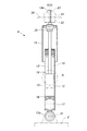
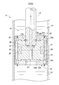
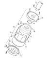
図1は実施形態に係るリヤサスペンションの斜視図であり、図2は実施形態に係るダンパの縦断面図であり、図3は図2中のIII部拡大図であり、図4は実施形態に係るピストンの分解斜視図であり、図5は実施形態に係るアウタヨークの平面図である。
[Embodiment]
1 is a perspective view of a rear suspension according to the embodiment, FIG. 2 is a longitudinal sectional view of a damper according to the embodiment, FIG. 3 is an enlarged view of a portion III in FIG. 2, and FIG. FIG. 5 is an exploded perspective view of the piston, and FIG. 5 is a plan view of the outer yoke according to the embodiment.
《実施形態の構成》
図1に示すように、本実施形態のリヤサスペンション1は、いわゆるH型トーションビーム式サスペンションであり、左右のトレーリングアーム2,3や、両トレーリングアーム2,3の中間部を連結するトーションビーム4、懸架ばねである左右一対のコイルスプリング5、左右一対のダンパ6等から構成されており、左右のリヤホイール7,8を懸架している。ダンパ6は、MRF(Magneto-Rheological Fluid:磁気粘性流体)を作動流体とする減衰力可変型ダンパであり、トランクルーム内等に設置されたECU9によってその減衰力が可変制御される。
<< Configuration of Embodiment >>
As shown in FIG. 1, the rear suspension 1 of the present embodiment is a so-called H-type torsion beam suspension, and the torsion beam 4 that connects the left and right trailing
<ダンパ>
図2に示すように、本実施形態のダンパ6は、モノチューブ式(ド・カルボン式)であり、MRFが充填された円筒状のシリンダ12と、このシリンダ12に対して軸方向に摺動するピストンロッド13と、ピストンロッド13の先端に装着されてシリンダ12内を上部液室(一側液室)14と下部液室(他側液室)15とに区画するピストン16と、シリンダ12の下部に高圧ガス室17を画成するフリーピストン18と、ピストンロッド13等への塵埃の付着を防ぐカバー19と、フルバウンド時における緩衝を行うバンプストップ20とを主要構成要素としている。
<Damper>
As shown in FIG. 2, the
シリンダ12は、下端のアイピース12aに嵌挿されたボルト21を介して、車輪側部材であるトレーリングアーム2の上面に連結されている。また、ピストンロッド13は、上下一対のブッシュ22とナット23とを介して、その上部ねじ軸13aが車体側部材であるダンパベース(ホイールハウス上部)24に連結されている。
The
<ピストン>
ピストン16は、MLV(Magnetizable Liquid Valve:磁気流体バルブ)と一体となっており、図3,図4に示すように、その外周面がシリンダ12の内壁面に摺接する鋼板製のピストンカバー30と、ピストンカバー30の内側に保持されたアウタヨーク31と、アウタヨーク31の内側に配置されたインナヨーク32と、アウタヨーク31およびインナヨーク32を軸方向に挟持する上下一対のエンドプレート33,34と、インナヨーク32の軸方向中央部に樹脂モールディングされたMLVコイル(磁界印加手段)35と、ピストン16をピストンロッド13に固定するための係止リング36とを主要構成要素としている。
<Piston>
The
アウタヨーク31やインナヨーク32、エンドプレート33,34は、ピストンカバー30の両端部を加締めることによって固定されている。また、係止リング36は、ばね鋼を素材とする線材をC字状に成形したものであり、ピストンロッド13に形成されたリング保持溝13bに外嵌するとともに、インナヨーク32とエンドプレート33との間に所定のばね力をもって係合/保持されている。図3中に符号37で示す部材はインナヨーク32の軸心に嵌挿されたプラグであり、符号38で示す部材は液圧シール用のOリングである。
The
アウタヨーク31は、強磁性材料を素材とした円筒状の一体成形品であり、エンドプレート33,34に形成された外縁フランジ33a,34aが内嵌する環状段差部31a,31bをその両端に有している。また、インナヨーク32も、強磁性材料を素材とした円柱状の一体成形品であり、エンドプレート33,34の端面に突設された円盤状凸部33b,34bが内嵌する環状フランジ32a,32bをその両端に有している。アウタヨーク31の内周面とインナヨーク32の外周面とは所定の間隙をもって対峙しており、これにより、アウタヨーク31とインナヨーク32との間に環状流路39が画成されている。
The
両エンドプレート33,34は、非磁性体であるアルミニウム合金(ジュラルミン)を素材とした円盤状のものであり、環状流路41を介して上部液室14と下部液室15とを連通させる4つの円弧状孔33c、34cをそれぞれ有している。また、エンドプレート33は、ピストンロッド13が内嵌するロッド孔33dを有している。
Both
<アウタヨーク>
図5に示すように、アウタヨーク31は、等角度間隔で分割された複数個(本実施形態では、8個)の分割ヨーク41と、隣接する分割ヨーク41を連結する薄肉の連結片(保持手段)42とからなっている。各分割ヨーク41は、連結片42によって拡径状態に保持されており、自由状態においてはその外周面がピストンカバー30の内周面に密着している。
<Outer York>
As shown in FIG. 5, the
《実施形態の作用》
自動車が走行を開始すると、ECU9は、前後Gセンサ、横Gセンサ、および上下Gセンサから得られた車体の加速度や、車速センサから入力した車体速度、車輪速センサから得られた各車輪の回転速度等に基づき各車輪についてダンパ6の目標減衰力を設定した後、MLVコイル35に対して駆動電流(励磁電流)を供給する。すると、図6に示すように、ピストン16内に磁界が形成され、環状流路39を流通するMRFの粘度が変化し、ダンパ6の減衰力が増大あるいは減少する。この際、本実施形態では、磁界によってアウタヨーク31を構成する分割ヨーク41がインナヨーク32側に引き寄せられ、環状流路39の流路面積が有意に減少して減衰力が従来装置に較べて有意に増大する。なお、環状流路39の流路面積は磁界の強さに対応して変化し、磁界が全く印加されない状態においては、図3に示すように最大となる。
<< Operation of Embodiment >>
When the vehicle starts traveling, the
本実施形態ではこのような構成を採ったことにより、MLVコイル35に供給する駆動電流の値を比較的小さく設定しながら減衰力の可変範囲を大きくすることができ、電力消費の低減や減衰力制御性(すなわち、操縦安定性や乗り心地)の向上等を実現できた。また、内径の異なるアウタヨーク31を複数種用意することにより、自動車の用途や車重等に応じてダンパ6の減衰力可変範囲を容易に変更できる。
By adopting such a configuration in the present embodiment, the variable range of the damping force can be increased while setting the value of the drive current supplied to the
<一部変形例>
図7は上記実施形態の一部変形例に係るアウタヨークを示す平面図である。
一部変形例は、上述した実施形態と略同様の構成を採っており、その作用も実施形態と同様であるが、アウタヨーク31の構造のみが異なっている。すなわち、一部変形例のアウタヨーク31では、分割ヨーク41が独立しているとともに、隣接する分割ヨーク41がばね鋼板製の連結プレート(弾性連結部材)43によって連結されている。連結プレート43は各分割ヨーク41を拡径方向に付勢しており、自由状態においては、実施形態と同様に各分割ヨーク41の外周面がピストンカバー30の内周面に密着する。一部変形例では、このような構成を採ったことにより、分割ヨーク41の素材としてフェライト等の弾性に乏しいものを用いても、拡径状態の保持が効果的かつ高い耐久性をもって行える。
<Some variations>
FIG. 7 is a plan view showing an outer yoke according to a partial modification of the embodiment.
Some modified examples have substantially the same configuration as that of the above-described embodiment, and the operation thereof is the same as that of the embodiment, but only the structure of the
以上で具体的実施形態の説明を終えるが、本発明は上記実施形態に限定されることなく幅広く変形実施することができる。例えば、上記実施形態は4輪自動車のリヤサスペンションを構成する減衰力可変式ダンパに本発明を適用したものであるが、本発明は、フロントサスペンション用の減衰力可変式ダンパにも適用できるし、2輪自動車等の減衰力可変ダンパ等にも適用可能である。また、保持手段としては、例えば、分割ヨークの両端に設置する環状スプリング等を採用してもよい。その他、アウタヨークやインナヨーク、エンドプレート等の具体的形状やダンパの具体的構造等についても、本発明の趣旨を逸脱しない範囲であれば適宜変更可能である。 Although the description of the specific embodiment is finished as described above, the present invention is not limited to the above embodiment and can be widely modified. For example, in the above embodiment, the present invention is applied to a damping force variable damper that constitutes a rear suspension of a four-wheeled vehicle. However, the present invention can also be applied to a damping force variable damper for a front suspension. It can also be applied to a damping force variable damper for a two-wheeled vehicle or the like. Moreover, as a holding means, you may employ | adopt the annular spring etc. which are installed in the both ends of a division | segmentation yoke, for example. In addition, the specific shape of the outer yoke, the inner yoke, the end plate, etc., the specific structure of the damper, and the like can be changed as appropriate without departing from the spirit of the present invention.
2 トレーリングアーム(車輪側部材)
6 ダンパ
12 シリンダ
13 ピストンロッド
14 上部液室(一側液室)
15 下部液室(他側液室)
16 ピストン
22 ダンパベース(車体側部材)
30 ピストンカバー
31 アウタヨーク
32 インナヨーク
33 エンドプレート
34 エンドプレート
35 MLVコイル
39 環状流路
41 分割ヨーク
42 連結片(保持手段)
43 連結プレート(弾性連結部材:保持手段)
2 Trailing arm (wheel side member)
6
15 Lower liquid chamber (other side liquid chamber)
16
30
43 connecting plate (elastic connecting member: holding means)
Claims (3)
前記ピストンは、
周方向に隣接する複数の分割ヨークから構成された円筒状のアウタヨークと、
前記アウタヨークを拡径状態に保持する保持手段と、
前記アウタヨークの内周面に対して所定の間隙をもって設置され、当該アウタヨークとの間に前記環状流路を画成するインナヨークと、
前記インナヨークに保持され、前記磁界の形成に供される磁界印加手段と
を備え、
前記分割ヨークが磁性体を素材とし、
前記磁界印加手段が磁界を形成していないときには前記分割ヨークから構成されたアウタヨークが前記保持手段によって拡径状態に保持される一方、前記磁界印加手段が磁界を形成したときに前記分割ヨークが当該磁界によって前記インナヨーク側に引き寄せられることを特徴とする減衰力可変ダンパ。 A cylinder filled with a magnetic fluid or a magnetorheological fluid and connected to one of a vehicle body side member and a wheel side member; and the cylinder is divided into a one side liquid chamber and another side liquid chamber and the magnetic fluid Alternatively, a piston having an annular flow path for allowing the magnetorheological fluid to flow between the one-side liquid chamber and the other-side liquid chamber, and the other of the vehicle body side member and the wheel side member are connected to the piston. A damping force variable damper that has a piston rod and whose damping force is controlled by applying a magnetic field to the magnetic fluid or the magnetorheological fluid passing through the annular flow path,
The piston is
A cylindrical outer yoke composed of a plurality of divided yokes adjacent in the circumferential direction;
Holding means for holding the outer yoke in an expanded state;
An inner yoke that is installed with a predetermined gap with respect to the inner peripheral surface of the outer yoke, and that defines the annular flow path with the outer yoke;
A magnetic field applying means held by the inner yoke and used for forming the magnetic field,
The split yoke is made of a magnetic material ,
When the magnetic field applying means does not form a magnetic field, the outer yoke constituted by the divided yoke is held in an expanded state by the holding means, while when the magnetic field applying means forms a magnetic field, the divided yoke A damping force variable damper which is attracted to the inner yoke side by a magnetic field .
Priority Applications (1)
| Application Number | Priority Date | Filing Date | Title |
|---|---|---|---|
| JP2007261694A JP4913006B2 (en) | 2007-10-05 | 2007-10-05 | Variable damping force damper |
Applications Claiming Priority (1)
| Application Number | Priority Date | Filing Date | Title |
|---|---|---|---|
| JP2007261694A JP4913006B2 (en) | 2007-10-05 | 2007-10-05 | Variable damping force damper |
Publications (2)
| Publication Number | Publication Date |
|---|---|
| JP2009092106A JP2009092106A (en) | 2009-04-30 |
| JP4913006B2 true JP4913006B2 (en) | 2012-04-11 |
Family
ID=40664302
Family Applications (1)
| Application Number | Title | Priority Date | Filing Date |
|---|---|---|---|
| JP2007261694A Expired - Fee Related JP4913006B2 (en) | 2007-10-05 | 2007-10-05 | Variable damping force damper |
Country Status (1)
| Country | Link |
|---|---|
| JP (1) | JP4913006B2 (en) |
Families Citing this family (2)
| Publication number | Priority date | Publication date | Assignee | Title |
|---|---|---|---|---|
| JP5828558B2 (en) | 2012-03-01 | 2015-12-09 | Kyb株式会社 | Magnetorheological fluid shock absorber |
| CN114810899A (en) * | 2022-05-24 | 2022-07-29 | 深圳市家信信息科技开发有限公司 | Vehicle damping system capable of quantitatively controlling damping force |
Family Cites Families (3)
| Publication number | Priority date | Publication date | Assignee | Title |
|---|---|---|---|---|
| JPS5911934A (en) * | 1982-07-12 | 1984-01-21 | Nissan Motor Co Ltd | Lighting structure for ceiling |
| JP2004221322A (en) * | 2003-01-15 | 2004-08-05 | Sharp Corp | Electromagnetic linear actuator |
| JP4447018B2 (en) * | 2006-02-23 | 2010-04-07 | 本田技研工業株式会社 | Variable damping force damper |
-
2007
- 2007-10-05 JP JP2007261694A patent/JP4913006B2/en not_active Expired - Fee Related
Also Published As
| Publication number | Publication date |
|---|---|
| JP2009092106A (en) | 2009-04-30 |
Similar Documents
| Publication | Publication Date | Title |
|---|---|---|
| EP2055985B1 (en) | Magneto-rheological damper | |
| US7958979B2 (en) | Variable damper | |
| JP5131678B2 (en) | Variable damping force damper | |
| US10690215B2 (en) | Damper with electro-magnetic actuator | |
| US8770358B2 (en) | Variable damping force damper | |
| US7896311B2 (en) | Solenoid valve of shock absorber | |
| JP3696358B2 (en) | Variable damping force damper | |
| JP4654236B2 (en) | Variable damping force damper | |
| WO2012132730A1 (en) | Front fork | |
| JPH05149364A (en) | Damping force regulating system hydraulic shock absorber | |
| JP4500820B2 (en) | Variable damping force damper | |
| JP2009216210A (en) | Damping force variable damper | |
| JP7066646B2 (en) | Variable stiffness bush | |
| JPH07501604A (en) | proportional pressure control valve | |
| JP2009133472A (en) | Damping force variable damper | |
| JP2012145171A (en) | Damping force variable damper | |
| JP2008175248A (en) | Damper device | |
| JP7066647B2 (en) | Variable stiffness bush | |
| JP4913006B2 (en) | Variable damping force damper | |
| JP2008223814A (en) | Variable damping force damper | |
| US9103398B2 (en) | Variable damping force damper | |
| JP2007187176A (en) | Damping force-variable damper and damping force-variable damper-equipped vehicle | |
| JP2009216209A (en) | Damping force variable damper | |
| JP2013087804A (en) | Damping force variable damper | |
| JP2003322195A (en) | Damping force adjusting hydraulic buffer |
Legal Events
| Date | Code | Title | Description |
|---|---|---|---|
| A621 | Written request for application examination |
Free format text: JAPANESE INTERMEDIATE CODE: A621 Effective date: 20091127 |
|
| A521 | Written amendment |
Free format text: JAPANESE INTERMEDIATE CODE: A523 Effective date: 20091215 |
|
| A131 | Notification of reasons for refusal |
Free format text: JAPANESE INTERMEDIATE CODE: A131 Effective date: 20110614 |
|
| A977 | Report on retrieval |
Free format text: JAPANESE INTERMEDIATE CODE: A971007 Effective date: 20110616 |
|
| A521 | Written amendment |
Free format text: JAPANESE INTERMEDIATE CODE: A523 Effective date: 20110803 |
|
| RD02 | Notification of acceptance of power of attorney |
Free format text: JAPANESE INTERMEDIATE CODE: A7422 Effective date: 20110911 |
|
| TRDD | Decision of grant or rejection written | ||
| A01 | Written decision to grant a patent or to grant a registration (utility model) |
Free format text: JAPANESE INTERMEDIATE CODE: A01 Effective date: 20111220 |
|
| A01 | Written decision to grant a patent or to grant a registration (utility model) |
Free format text: JAPANESE INTERMEDIATE CODE: A01 |
|
| A61 | First payment of annual fees (during grant procedure) |
Free format text: JAPANESE INTERMEDIATE CODE: A61 Effective date: 20120118 |
|
| R150 | Certificate of patent or registration of utility model |
Ref document number: 4913006 Country of ref document: JP Free format text: JAPANESE INTERMEDIATE CODE: R150 Free format text: JAPANESE INTERMEDIATE CODE: R150 |
|
| FPAY | Renewal fee payment (event date is renewal date of database) |
Free format text: PAYMENT UNTIL: 20150127 Year of fee payment: 3 |
|
| LAPS | Cancellation because of no payment of annual fees |