JP2012145171A - Damping force variable damper - Google Patents
Damping force variable damper Download PDFInfo
- Publication number
- JP2012145171A JP2012145171A JP2011004355A JP2011004355A JP2012145171A JP 2012145171 A JP2012145171 A JP 2012145171A JP 2011004355 A JP2011004355 A JP 2011004355A JP 2011004355 A JP2011004355 A JP 2011004355A JP 2012145171 A JP2012145171 A JP 2012145171A
- Authority
- JP
- Japan
- Prior art keywords
- valve
- piston
- damping force
- oil chamber
- valve plate
- Prior art date
- Legal status (The legal status is an assumption and is not a legal conclusion. Google has not performed a legal analysis and makes no representation as to the accuracy of the status listed.)
- Granted
Links
Images


Landscapes
- Vehicle Body Suspensions (AREA)
- Fluid-Damping Devices (AREA)
Abstract
Description
本発明は、自動車のサスペンションに用いられる減衰力可変ダンパに係り、制御用電力の低減や制御性の向上等を実現する技術に関する。 The present invention relates to a damping force variable damper used for a suspension of an automobile, and relates to a technique for realizing reduction of control power, improvement of controllability, and the like.
サスペンションは、自動車の走行安定性を左右する重要な要素であり、車体に対して車輪を上下動自在に支持させるためのリンク(アームやロッド類)と、撓むことにより路面からの衝撃等を吸収するスプリングと、スプリングの振動を減衰させるダンパとを主要構成部材としている。自動車サスペンション用のダンパでは、作動油が充填された円筒状のシリンダとこのシリンダ内で摺動するピストンが先端に装着されたピストンロッドとを備え、ピストン(ピストンロッド)の作動に伴って作動油が複数の油室間を移動する複筒式や単筒式の筒型が一般的である。 Suspension is an important factor that affects the running stability of an automobile, and links (arms and rods) that support the wheels so that they can move up and down with respect to the vehicle body and impact from the road surface by bending. The main constituent members are the absorbing spring and the damper that attenuates the vibration of the spring. A damper for an automobile suspension includes a cylindrical cylinder filled with hydraulic oil and a piston rod with a piston sliding at the tip of the cylinder, and the hydraulic oil is moved along with the operation of the piston (piston rod). In general, a double cylinder type or a single cylinder type that moves between a plurality of oil chambers is generally used.
筒型ダンパでは、ピストンに連通孔やバルブプレートを設け、作動油が油室間で移動する際に流動抵抗を与えて減衰力を得るものが一般的である。しかし、このようなダンパでは減衰特性が一定となることから、路面状態および走行状況に適した乗り心地や走行安定性を得ることができない。そこで、ピストンの上下面に磁性体を素材とする縮み側および伸び側のバルブプレートを設置するとともに、ピストン内に磁界を発生させる環状のコイルを埋設し、コイルへの通電量を増減することで磁界の強さを変化させ、これによってバルブプレートの開弁特性(すなわち、減衰力)を無段階に変化させる減衰力可変ダンパが提案されている(特許文献1参照)。 In the cylindrical damper, a piston is generally provided with a communication hole or a valve plate, and when the hydraulic oil moves between oil chambers, a flow resistance is given to obtain a damping force. However, since such a damper has a constant damping characteristic, it is not possible to obtain riding comfort and running stability suitable for the road surface condition and the running condition. Therefore, by installing the contraction side and extension side valve plates made of magnetic material on the upper and lower surfaces of the piston, and by embedding an annular coil that generates a magnetic field in the piston, the amount of current flowing through the coil can be increased or decreased. There has been proposed a damping force variable damper that changes the strength of a magnetic field and thereby changes the valve opening characteristics (that is, damping force) of the valve plate steplessly (see Patent Document 1).
特許文献1の減衰力可変ダンパでは、磁界によってバルブプレートの開弁特性を変化させる都合上、以下に述べるような問題を有していた。すなわち、コイルによる磁力はコイルとバルブプレートとの距離の2乗に反比例するため、バルブプレートが作動油の流体圧によって大きく開いた場合には、バルブプレートが閉じている場合に較べると、バルブプレートをピストン側に引き寄せるために非常に大きな磁力が必要となる。そのため、この減衰力可変ダンパでは、目標減衰力が一定であってもコイルに大きな電力を供給し続けなければならず、車載バッテリの容量を大きくする必要があるだけでなく、オルタネータの発電負荷が大きくなる(エンジンの駆動損失が多くなる)問題があった。また、バルブプレートが開いた状態ではコイルの磁力がバルブプレートに及びにくいため、減衰力制御を正確に行うことが難しく、減衰力の急増または急減によってサスペンションから振動や異音が発生する虞もあった。
The damping force variable damper of
本発明は、このような背景に鑑みなされたもので、制御用電力の低減や制御性の向上等を実現した減衰力可変ダンパを提供することを目的とする。 The present invention has been made in view of such a background, and an object thereof is to provide a damping force variable damper that realizes reduction of control power, improvement of controllability, and the like.
本発明に係る減衰力可変ダンパは、車体側部材と車輪側部材とのどちらか一方に連結され、その内部に作動油が封入された円筒状のシリンダと、前記シリンダ内を往復動し、当該シリンダ内をロッド側油室とピストン側油室とに区画するとともに、前記作動油を当該ロッド側油室と当該ピストン側油室との間で流通させる軸方向孔、および軸方向中間位置に形成されるとともに当該軸方向孔の側面に開口するバルブスロットを有する円柱状のピストンと、車体側部材と車輪側部材とのどちらか他方に連結されるとともに、前記ピストンをその先端に保持したピストンロッドと、前記バルブスロットに移動自在に保持され、前記軸方向孔内に出没する弾性弁部、および当該弾性弁部に所定の間隙をもって対峙する閉鎖板部を有するバルブプレートと、前記バルブプレートを駆動するバルブプレート駆動手段とを有し、前記弾性弁部は、前記バルブプレートの移動に伴って前記軸方向孔内での突出量が変化し、前記バルブスロットにおける当該軸方向孔側の開口端によって片持ち支持された状態で前記作動油の流体圧によって開弁する。 The damping force variable damper according to the present invention is connected to one of the vehicle body side member and the wheel side member, and reciprocates within the cylinder, and a cylindrical cylinder in which hydraulic oil is sealed. The cylinder is divided into a rod-side oil chamber and a piston-side oil chamber, and is formed in an axial hole that allows the hydraulic oil to flow between the rod-side oil chamber and the piston-side oil chamber, and an axially intermediate position. And a piston rod having a valve slot that opens to a side surface of the axial hole, and a piston rod that is connected to either the vehicle body side member or the wheel side member and that holds the piston at the tip thereof A valve plate that is movably held in the valve slot and protrudes and disappears in the axial hole, and a closing plate portion that faces the elastic valve portion with a predetermined gap. And a valve plate driving means for driving the valve plate, and the elastic valve portion changes in a protruding amount in the axial hole as the valve plate moves, and the shaft in the valve slot changes. The valve is opened by the hydraulic pressure of the hydraulic oil while being cantilevered by the opening end on the direction hole side.
また、本発明の第2の側面では、前記バルブプレートは、前記ピストンの軸心を回転中心として、前記バルブスロットに回転自在に保持される。 In the second aspect of the present invention, the valve plate is rotatably held in the valve slot around the axis of the piston as a rotation center.
また、本発明の第3の側面では、前記弾性弁部は、前記ピストンの軸方向視で略円弧状を呈するとともに、基端が前記閉鎖板部に接続する。 In the third aspect of the present invention, the elastic valve portion has a substantially arc shape when viewed in the axial direction of the piston, and a proximal end is connected to the closing plate portion.
また、本発明の第4の側面では、前記弾性弁部は、前記ロッド側油室から前記ピストン側油室に前記作動油が流入する際と、前記ピストン側油室から前記ロッド側油室に前記作動油が流入する際とで、その開弁抵抗が異なる。 Further, in the fourth aspect of the present invention, the elastic valve portion is configured such that when the hydraulic oil flows from the rod side oil chamber into the piston side oil chamber, and from the piston side oil chamber to the rod side oil chamber. The valve opening resistance differs depending on the flow of the hydraulic oil.
本発明によれば、比較的簡易かつ安価な構成でありながら、バルブプレートの変位によって所望の減衰力を得ることができるため、制御用電力の低減や制御性の向上等を実現できる。また、バルブプレートがバルブスロットに回転自在に保持されたものでは、バルブプレート駆動手段として簡易な構造のものを採用できる。また、バルブプレートが金属板を素材とし、弾性弁部が、ピストンの軸方向視で略円弧状を呈するとともに、基端が前記閉鎖板部に接続するものでは、生産性の向上やコストの低減を実現することができる。また、作動油の流入方向によって弾性弁部の開弁抵抗が異なるものでは、ダンパの縮み側と伸び側とで減衰力を異ならせることができる。 According to the present invention, a desired damping force can be obtained by the displacement of the valve plate while having a relatively simple and inexpensive configuration, so that it is possible to reduce control power and improve controllability. In addition, when the valve plate is rotatably held in the valve slot, a simple structure can be adopted as the valve plate driving means. Further, when the valve plate is made of a metal plate and the elastic valve portion has a substantially arc shape when viewed in the axial direction of the piston, and the base end is connected to the closing plate portion, the productivity is improved and the cost is reduced. Can be realized. Further, when the opening resistance of the elastic valve portion is different depending on the inflow direction of the hydraulic oil, the damping force can be made different between the contraction side and the extension side of the damper.
以下、図面を参照して、本発明を4輪自動車用の筒型減衰力可変ダンパに適用した一実施形態を詳細に説明する。 Hereinafter, an embodiment in which the present invention is applied to a tubular damping force variable damper for a four-wheel vehicle will be described in detail with reference to the drawings.
≪実施形態の構成≫
<サスペンション>
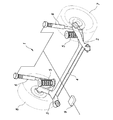
図1に示すように、本実施形態のリヤサスペンション1は、いわゆるH型トーションビーム式サスペンションであり、左右のトレーリングアーム2,3や、両トレーリングアーム2,3の中間部を連結するトーションビーム4、懸架ばねである左右一対のコイルスプリング5、左右一対のダンパ6等から構成されており、左右のリヤホイール7,8を懸架している。ダンパ6は、電気制御式の減衰力可変型ダンパであり、トランクルーム内等に設置された減衰力制御用のECU9によってその減衰力が可変制御される。なお、左右のダンパ6は同一品であるため、その説明は左側のものについてのみ行う。
<< Configuration of Embodiment >>
<Suspension>
As shown in FIG. 1, the
<ダンパ>
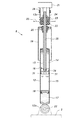
図2に示すように、本実施形態のダンパ6は、モノチューブ式(ド・カルボン式)であり、作動油が充填された円筒状のシリンダ12と、シリンダ12に対して軸方向に摺動するピストンロッド13と、ピストンロッド13の先端に装着されてシリンダ12内をロッド側油室14とピストン側油室15とに区画するピストン16と、シリンダ12の下部に高圧ガス室17を画成するフリーピストン18と、ピストンロッド13等への塵埃の付着を防ぐカバー19と、フルバウンド時における緩衝を行うバンプストップ20と、後述するバルブプレート34の駆動に供される電動式のアクチュエータ21とを主要構成要素としている。
<Damper>
As shown in FIG. 2, the
シリンダ12は、下端のアイピース12aに嵌挿されたボルト22を介して、車輪側部材であるトレーリングアーム2の上面に連結されている。また、ピストンロッド13は、上下一対のブッシュ23とナット24とを介して、その上部ねじ軸13aが車体側部材であるダンパベース(ホイールハウス上部)25に連結されている。また、アクチュエータ21は、ブラケット26を介して上側のブッシュ23の上部に固定されている。
The
<減衰力調整機構>
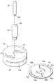
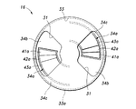
図3,図4に示すように、ピストン16には、扇状断面を呈する一対の軸方向孔31が180°間隔で穿設されるとともに、円形断面のバルブスロット33が軸方向中央に形成されている。バルブスロット33は、外周面に開口33aを有しており、この開口33aから円盤状のバルブプレート34が挿入される。ピストンロッド13は中空構造となっており、その中空部13bにアクチュエータ21の駆動力をバルブプレート34に伝達するコントロールロッド35が回転自在に保持されている。
<Damping force adjustment mechanism>
As shown in FIGS. 3 and 4, the
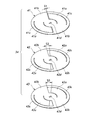
バルブプレート34は、円弧状を呈する一対の弾性弁部34aと、扇状を呈するとともに両弾性弁部34aの基端が連続する一対の閉鎖板部34bと、両閉鎖板部34bの外周端を連結する一対の連結弧部34cと、コントロールロッド35の駆動突起35aが嵌入する矩形孔34dとを有している。図5に示すように、バルブプレート34は、ばね鋼製の第1〜第3プレート41〜43によって構成されている。第1〜第3プレート41〜43は、組み付けを容易にすべくスポット溶接によって一体化されているが、接着やリベット等によって一体化されていてもよいし、必ずしも一体化されていなくてもよい。
The
第1〜第3プレート41〜43は、バルブプレート34と同様に、一対の弾性弁部41a〜43aと、一対の閉鎖板部41b〜43bと、一対の連結弧部41c〜43cと、矩形孔41d〜43dとをそれぞれ有しているが、弾性弁部41a〜43a間でその先端と閉鎖板部41b〜43bとの間隙S1〜S3がそれぞれ異なっている。すなわち、間隙S1は最も小さく、間隙S1が間隙S2よりも大きく、間隙S2が間隙S3よりも大きく設定されている。
Like the
≪実施形態の作用≫
自動車が走行を開始すると、ECU9は、各種センサから入力した車体加速度(横加速度や上下加速度)、車体速度、操舵角等に基づき、自動車の運動状態を推定する。次に、ECU9は、自動車の運動状態に応じてダンパ6の目標減衰力を設定した後、アクチュエータ21に駆動電流を出力する。すると、アクチュエータ21によってコントロールロッド35が回転駆動され、コントロールロッド35の下端に連結されたバルブプレート34が回転する。
<< Operation of Embodiment >>
When the vehicle starts running, the ECU 9 estimates the motion state of the vehicle based on vehicle body acceleration (lateral acceleration and vertical acceleration), vehicle body speed, steering angle, and the like input from various sensors. Next, the ECU 9 sets a target damping force of the
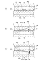
目標減衰力が中程度の場合、図6(a)に示すように、ECU9は、軸方向孔31内で弾性弁部34aの占有面積と閉鎖板部34bの占有面積とが略同一となるように、バルブプレート34の回転位相(すなわち、弾性弁部34aの突出量)を制御する。弾性弁部34aは、バルブスロット33における軸方向孔31側の開口端33bによって片持ち支持され、ダンパ6の短縮時(バウンド時)においては、図6(b)に示すように、作動油の流体圧によって第1プレート41の弾性弁部41aのみが弾性変形し(すなわち、開弁し)、ピストン16が比較的小さな抵抗を伴って下降する。また、ダンパ6の伸張時(リバウンド時)においては、図6(c)に示すように、作動油の流体圧によって第1〜第3プレート41〜43の弾性弁部41a〜43aの全てが弾性変形し、ピストン16が比較的大きな抵抗を伴って上昇することにより、中程度の減衰力が生起される。
When the target damping force is medium, as shown in FIG. 6A, the ECU 9 makes the occupation area of the
また、目標減衰力が高い場合、図7(a)に示すように、ECU9は、軸方向孔31内で弾性弁部34aの占有面積が閉鎖板部34bの占有面積よりも少なくなるように、バルブプレート34の回転位相を変化させる。すると、図7(b),(c)に示すように、ダンパ6のバウンド時における弾性弁部41aの弾性変形と、リバウンド時における弾性弁部41a〜43aの弾性変形とがともに生じにくくなり、高い減衰力が生起される。
Further, when the target damping force is high, as shown in FIG. 7A, the ECU 9 causes the area occupied by the
一方、目標減衰力が低い場合、図8(a)に示すように、ECU9は、軸方向孔31内で弾性弁部34aの占有面積が閉鎖板部34bの占有面積よりも大きくなるように、バルブプレート34の回転位相を変化させる。すると、図8(b),(c)に示すように、ダンパ6のバウンド時における弾性弁部41aの弾性変形と、リバウンド時における弾性弁部41a〜43aの弾性変形とがともに生じやすくなり、低い減衰力が生起される。
On the other hand, when the target damping force is low, as shown in FIG. 8 (a), the ECU 9 causes the occupied area of the
本実施形態では、このような構成を採ったことにより、前述した電磁力を用いる従来装置に較べ、制御に係る電力消費をごく少なく抑えながら、無段階の減衰力制御を高精度かつ安定的に実現することができた。また、目標減衰力が変化しないときにはアクチュエータ21によるバルブプレート34の駆動が行われないため、電力消費が更に低減されるとともに、バルブプレート34やバルブスロット33の摩耗等も抑えられることでダンパ6の耐久性が向上した。
In this embodiment, by adopting such a configuration, the stepless damping force control can be performed with high accuracy and stability while suppressing power consumption related to the control as compared with the conventional device using the electromagnetic force described above. Could be realized. Further, when the target damping force does not change, the
以上で実施形態の説明を終えるが、本発明の態様はこれらに限られるものではない。例えば、上記実施形態はリヤサスペンションに用いられる単筒式の減衰力可変ダンパに本発明を適用したものであるが、本発明は、フロントサスペンション用の減衰力可変ダンパや、複筒式の減衰力可変ダンパにも当然に適用可能である。また、上記実施形態では一体品のピストンにバルブスロットを形成するようにしたが、ピストンをアッパハーフとロワハーフとに2分割し、アッパハーフとロワハーフとの間にバルブプレートを挟持させるようにしてもよい。また、上記実施形態ではバルブプレートとして3枚のばね鋼板製のプレートからなるものを採用したが、バルブプレートは、4枚以上のプレートから構成するようにしてもよいし、1枚あるいは2枚のプレートから構成するようにしてもよい。更に、上記実施形態では弾性弁部と閉鎖板部とが一体のバルブプレートを回転駆動するようにしたが、閉鎖板部に弾性弁部がスポット溶接等によって接合されたバルブプレートを採用してもよいし、バルブプレートを直線的に駆動するものとしてもよい。その他、減衰力可変ダンパやバルブプレートの具体的構造や形状等についても、本発明の主旨を逸脱しない範囲で適宜変更可能である。 This is the end of the description of the embodiment. However, aspects of the present invention are not limited to these. For example, in the above embodiment, the present invention is applied to a single-cylinder variable damping force damper used for a rear suspension. However, the present invention is applicable to a variable damping force damper for a front suspension or a multi-cylinder damping force. Naturally, it can also be applied to a variable damper. In the above embodiment, the valve slot is formed in the integral piston. However, the piston may be divided into two parts, the upper half and the lower half, and the valve plate may be sandwiched between the upper half and the lower half. In the above embodiment, the valve plate is composed of three spring steel plates. However, the valve plate may be composed of four or more plates, or one or two plates. You may make it comprise from a plate. Further, in the above embodiment, the elastic valve portion and the closing plate portion are driven to rotate the integral valve plate, but a valve plate in which the elastic valve portion is joined to the closing plate portion by spot welding or the like may be adopted. Alternatively, the valve plate may be driven linearly. In addition, the specific structure and shape of the damping force variable damper and the valve plate can be appropriately changed without departing from the gist of the present invention.
2 トレーリングアーム(車輪側部材)
6 ダンパ(減衰力可変ダンパ)
12 シリンダ
13 ピストンロッド
14 ロッド側油室
15 ピストン側油室
16 ピストン
21 アクチュエータ(バルブプレート駆動手段)
25 ダンパベース(車体側部材)
31 軸方向孔
33 バルブスロット
33b 開口端
34 バルブプレート
34a 弾性弁部
34b 閉鎖板部
35 コントロールロッド
41 第1プレート
42 第2プレート
43 第3プレート
2 Trailing arm (wheel side member)
6 Damper (Damping force variable damper)
12
25 Damper base (vehicle body side member)
31
Claims (4)
前記シリンダ内を往復動し、当該シリンダ内をロッド側油室とピストン側油室とに区画するとともに、前記作動油を当該ロッド側油室と当該ピストン側油室との間で流通させる軸方向孔、および軸方向中間位置に形成されるとともに当該軸方向孔の側面に開口するバルブスロットを有する円柱状のピストンと、
車体側部材と車輪側部材とのどちらか他方に連結されるとともに、前記ピストンをその先端に保持したピストンロッドと、
前記バルブスロットに移動自在に保持され、前記軸方向孔内に出没する弾性弁部、および当該弾性弁部に所定の間隙をもって対峙する閉鎖板部を有するバルブプレートと、
前記バルブプレートを駆動するバルブプレート駆動手段と
を有し、
前記弾性弁部は、前記バルブプレートの移動に伴って前記軸方向孔内での突出量が変化し、前記バルブスロットにおける当該軸方向孔側の開口端によって片持ち支持された状態で前記作動油の流体圧によって開弁することを特徴とする減衰力可変ダンパ。 A cylindrical cylinder connected to one of the vehicle body side member and the wheel side member, and filled with hydraulic oil therein,
Axial direction that reciprocates in the cylinder, divides the cylinder into a rod side oil chamber and a piston side oil chamber, and distributes the hydraulic oil between the rod side oil chamber and the piston side oil chamber A cylindrical piston having a hole and a valve slot formed at an axially intermediate position and opening on a side surface of the axial hole;
A piston rod connected to the other of the vehicle body side member and the wheel side member, and holding the piston at its tip;
A valve plate having an elastic valve portion that is movably held in the valve slot and protrudes and disappears in the axial hole, and a closing plate portion facing the elastic valve portion with a predetermined gap;
Valve plate driving means for driving the valve plate,
The elastic valve portion changes in the amount of protrusion in the axial hole with the movement of the valve plate, and the hydraulic oil is cantilevered by the opening end of the valve slot on the axial hole side. The damping force variable damper is characterized in that the valve is opened by the fluid pressure.
Priority Applications (1)
| Application Number | Priority Date | Filing Date | Title |
|---|---|---|---|
| JP2011004355A JP5752427B2 (en) | 2011-01-12 | 2011-01-12 | Variable damping force damper |
Applications Claiming Priority (1)
| Application Number | Priority Date | Filing Date | Title |
|---|---|---|---|
| JP2011004355A JP5752427B2 (en) | 2011-01-12 | 2011-01-12 | Variable damping force damper |
Publications (2)
| Publication Number | Publication Date |
|---|---|
| JP2012145171A true JP2012145171A (en) | 2012-08-02 |
| JP5752427B2 JP5752427B2 (en) | 2015-07-22 |
Family
ID=46788933
Family Applications (1)
| Application Number | Title | Priority Date | Filing Date |
|---|---|---|---|
| JP2011004355A Expired - Fee Related JP5752427B2 (en) | 2011-01-12 | 2011-01-12 | Variable damping force damper |
Country Status (1)
| Country | Link |
|---|---|
| JP (1) | JP5752427B2 (en) |
Cited By (7)
| Publication number | Priority date | Publication date | Assignee | Title |
|---|---|---|---|---|
| CN103697104A (en) * | 2013-12-21 | 2014-04-02 | 浙江玛斯特汽配有限公司 | Adjustable electromagnetic suspension system |
| KR20170129462A (en) * | 2016-05-17 | 2017-11-27 | 자동차부품연구원 | Wheel suspension system capable of energy regeneration and suspension control |
| KR20200086813A (en) * | 2019-01-10 | 2020-07-20 | 동의대학교 산학협력단 | Smart vibration damping device |
| KR20220065558A (en) * | 2020-11-13 | 2022-05-20 | 한성대학교 산학협력단 | A two-wheeled vehicle suspension with variable damping force |
| CN115539554A (en) * | 2022-09-20 | 2022-12-30 | 重庆交通大学 | Damping adjusting valve with limiting device |
| CN115574037A (en) * | 2022-09-28 | 2023-01-06 | 重庆交通大学 | Damping continuously adjustable shock absorber |
| CN116146646A (en) * | 2023-01-09 | 2023-05-23 | 宁波德业粉末冶金有限公司 | Compression valve seat and compression valve for shock absorber |
Families Citing this family (1)
| Publication number | Priority date | Publication date | Assignee | Title |
|---|---|---|---|---|
| CN109958733B (en) * | 2017-12-22 | 2021-02-05 | 株式会社万都 | Piston valve assembly with variable damping force and shock absorber |
Citations (6)
| Publication number | Priority date | Publication date | Assignee | Title |
|---|---|---|---|---|
| US3164225A (en) * | 1961-09-06 | 1965-01-05 | Bourcier Christian-Marie-Luci | Shock absorbers having annular disc valving |
| JPS5973639A (en) * | 1982-10-15 | 1984-04-25 | Kayaba Ind Co Ltd | Vortex flow type hydraulic shock absorber |
| US4724937A (en) * | 1984-09-04 | 1988-02-16 | General Motors Corporation | Hydraulic damper for vehicles with variable deflected disk piston valving |
| JPS6449741U (en) * | 1987-09-24 | 1989-03-28 | ||
| JP2007146950A (en) * | 2005-11-25 | 2007-06-14 | Showa Corp | Front fork |
| JP2009185840A (en) * | 2008-02-04 | 2009-08-20 | Dome Co Ltd | Damping force adjusting device of shock absorber |
-
2011
- 2011-01-12 JP JP2011004355A patent/JP5752427B2/en not_active Expired - Fee Related
Patent Citations (6)
| Publication number | Priority date | Publication date | Assignee | Title |
|---|---|---|---|---|
| US3164225A (en) * | 1961-09-06 | 1965-01-05 | Bourcier Christian-Marie-Luci | Shock absorbers having annular disc valving |
| JPS5973639A (en) * | 1982-10-15 | 1984-04-25 | Kayaba Ind Co Ltd | Vortex flow type hydraulic shock absorber |
| US4724937A (en) * | 1984-09-04 | 1988-02-16 | General Motors Corporation | Hydraulic damper for vehicles with variable deflected disk piston valving |
| JPS6449741U (en) * | 1987-09-24 | 1989-03-28 | ||
| JP2007146950A (en) * | 2005-11-25 | 2007-06-14 | Showa Corp | Front fork |
| JP2009185840A (en) * | 2008-02-04 | 2009-08-20 | Dome Co Ltd | Damping force adjusting device of shock absorber |
Cited By (11)
| Publication number | Priority date | Publication date | Assignee | Title |
|---|---|---|---|---|
| CN103697104A (en) * | 2013-12-21 | 2014-04-02 | 浙江玛斯特汽配有限公司 | Adjustable electromagnetic suspension system |
| KR20170129462A (en) * | 2016-05-17 | 2017-11-27 | 자동차부품연구원 | Wheel suspension system capable of energy regeneration and suspension control |
| KR101897071B1 (en) * | 2016-05-17 | 2018-09-12 | 자동차부품연구원 | Wheel suspension system capable of energy regeneration and suspension control |
| KR20200086813A (en) * | 2019-01-10 | 2020-07-20 | 동의대학교 산학협력단 | Smart vibration damping device |
| KR102162599B1 (en) * | 2019-01-10 | 2020-10-07 | 동의대학교 산학협력단 | Smart vibration damping device |
| KR20220065558A (en) * | 2020-11-13 | 2022-05-20 | 한성대학교 산학협력단 | A two-wheeled vehicle suspension with variable damping force |
| KR102410227B1 (en) | 2020-11-13 | 2022-06-20 | 한성대학교 산학협력단 | A two-wheeled vehicle suspension with variable damping force |
| CN115539554A (en) * | 2022-09-20 | 2022-12-30 | 重庆交通大学 | Damping adjusting valve with limiting device |
| CN115574037A (en) * | 2022-09-28 | 2023-01-06 | 重庆交通大学 | Damping continuously adjustable shock absorber |
| CN116146646A (en) * | 2023-01-09 | 2023-05-23 | 宁波德业粉末冶金有限公司 | Compression valve seat and compression valve for shock absorber |
| CN116146646B (en) * | 2023-01-09 | 2023-07-25 | 宁波德业粉末冶金有限公司 | Compression valve seat and compression valve for shock absorber |
Also Published As
| Publication number | Publication date |
|---|---|
| JP5752427B2 (en) | 2015-07-22 |
Similar Documents
| Publication | Publication Date | Title |
|---|---|---|
| JP5752427B2 (en) | Variable damping force damper | |
| JP5636502B2 (en) | Variable damping force damper | |
| JP5619796B2 (en) | Variable damping force damper | |
| US10690215B2 (en) | Damper with electro-magnetic actuator | |
| CN113646558B (en) | Damper with side collector and external control valve | |
| US6651787B2 (en) | Vibration damper | |
| CN113195932B (en) | Damper with single external control valve | |
| JP2016513043A (en) | Autonomous control damper | |
| JP2008062895A (en) | Electrical device control system | |
| JP2017100697A (en) | Suspension device | |
| JP2020508255A (en) | Chassis parts with rotary damper | |
| JP2020133703A (en) | Variable stiffness bushing | |
| JP4500820B2 (en) | Variable damping force damper | |
| JP4654236B2 (en) | Variable damping force damper | |
| US10589591B2 (en) | Active damper system actuator arrangement | |
| JP2020133704A (en) | Variable rigidity bush | |
| JP5738418B2 (en) | Variable damping force damper | |
| JP5818201B2 (en) | Shock absorber | |
| JP2008223814A (en) | Variable damping force damper | |
| JP5661019B2 (en) | Variable damping force damper | |
| JP2007187176A (en) | Damping force-variable damper and damping force-variable damper-equipped vehicle | |
| JP2012052594A (en) | Adjustable damping force damper | |
| JP4913006B2 (en) | Variable damping force damper | |
| JP2008249030A (en) | Variable damping force damper | |
| JP5789104B2 (en) | Pneumatic shock absorber |
Legal Events
| Date | Code | Title | Description |
|---|---|---|---|
| A621 | Written request for application examination |
Free format text: JAPANESE INTERMEDIATE CODE: A621 Effective date: 20131128 |
|
| A977 | Report on retrieval |
Free format text: JAPANESE INTERMEDIATE CODE: A971007 Effective date: 20140724 |
|
| A131 | Notification of reasons for refusal |
Free format text: JAPANESE INTERMEDIATE CODE: A131 Effective date: 20140729 |
|
| A521 | Written amendment |
Free format text: JAPANESE INTERMEDIATE CODE: A523 Effective date: 20140904 |
|
| A131 | Notification of reasons for refusal |
Free format text: JAPANESE INTERMEDIATE CODE: A131 Effective date: 20150303 |
|
| A521 | Written amendment |
Free format text: JAPANESE INTERMEDIATE CODE: A523 Effective date: 20150415 |
|
| TRDD | Decision of grant or rejection written | ||
| A01 | Written decision to grant a patent or to grant a registration (utility model) |
Free format text: JAPANESE INTERMEDIATE CODE: A01 Effective date: 20150512 |
|
| A61 | First payment of annual fees (during grant procedure) |
Free format text: JAPANESE INTERMEDIATE CODE: A61 Effective date: 20150520 |
|
| R150 | Certificate of patent or registration of utility model |
Ref document number: 5752427 Country of ref document: JP Free format text: JAPANESE INTERMEDIATE CODE: R150 |
|
| LAPS | Cancellation because of no payment of annual fees |