US11215240B2 - Clutch release bearing device - Google Patents
Clutch release bearing device Download PDFInfo
- Publication number
- US11215240B2 US11215240B2 US16/624,243 US201816624243A US11215240B2 US 11215240 B2 US11215240 B2 US 11215240B2 US 201816624243 A US201816624243 A US 201816624243A US 11215240 B2 US11215240 B2 US 11215240B2
- Authority
- US
- United States
- Prior art keywords
- side plate
- release bearing
- release
- clutch release
- steel sheet
- Prior art date
- Legal status (The legal status is an assumption and is not a legal conclusion. Google has not performed a legal analysis and makes no representation as to the accuracy of the status listed.)
- Active, expires
Links
Images


Classifications
-
- F—MECHANICAL ENGINEERING; LIGHTING; HEATING; WEAPONS; BLASTING
- F16—ENGINEERING ELEMENTS AND UNITS; GENERAL MEASURES FOR PRODUCING AND MAINTAINING EFFECTIVE FUNCTIONING OF MACHINES OR INSTALLATIONS; THERMAL INSULATION IN GENERAL
- F16D—COUPLINGS FOR TRANSMITTING ROTATION; CLUTCHES; BRAKES
- F16D23/00—Details of mechanically-actuated clutches not specific for one distinct type
- F16D23/12—Mechanical clutch-actuating mechanisms arranged outside the clutch as such
- F16D23/14—Clutch-actuating sleeves or bearings; Actuating members directly connected to clutch-actuating sleeves or bearings
-
- F—MECHANICAL ENGINEERING; LIGHTING; HEATING; WEAPONS; BLASTING
- F16—ENGINEERING ELEMENTS AND UNITS; GENERAL MEASURES FOR PRODUCING AND MAINTAINING EFFECTIVE FUNCTIONING OF MACHINES OR INSTALLATIONS; THERMAL INSULATION IN GENERAL
- F16C—SHAFTS; FLEXIBLE SHAFTS; ELEMENTS OR CRANKSHAFT MECHANISMS; ROTARY BODIES OTHER THAN GEARING ELEMENTS; BEARINGS
- F16C19/00—Bearings with rolling contact, for exclusively rotary movement
- F16C19/02—Bearings with rolling contact, for exclusively rotary movement with bearing balls essentially of the same size in one or more circular rows
- F16C19/14—Bearings with rolling contact, for exclusively rotary movement with bearing balls essentially of the same size in one or more circular rows for both radial and axial load
- F16C19/16—Bearings with rolling contact, for exclusively rotary movement with bearing balls essentially of the same size in one or more circular rows for both radial and axial load with a single row of balls
-
- F—MECHANICAL ENGINEERING; LIGHTING; HEATING; WEAPONS; BLASTING
- F16—ENGINEERING ELEMENTS AND UNITS; GENERAL MEASURES FOR PRODUCING AND MAINTAINING EFFECTIVE FUNCTIONING OF MACHINES OR INSTALLATIONS; THERMAL INSULATION IN GENERAL
- F16C—SHAFTS; FLEXIBLE SHAFTS; ELEMENTS OR CRANKSHAFT MECHANISMS; ROTARY BODIES OTHER THAN GEARING ELEMENTS; BEARINGS
- F16C2326/00—Articles relating to transporting
- F16C2326/01—Parts of vehicles in general
-
- F—MECHANICAL ENGINEERING; LIGHTING; HEATING; WEAPONS; BLASTING
- F16—ENGINEERING ELEMENTS AND UNITS; GENERAL MEASURES FOR PRODUCING AND MAINTAINING EFFECTIVE FUNCTIONING OF MACHINES OR INSTALLATIONS; THERMAL INSULATION IN GENERAL
- F16D—COUPLINGS FOR TRANSMITTING ROTATION; CLUTCHES; BRAKES
- F16D23/00—Details of mechanically-actuated clutches not specific for one distinct type
- F16D23/12—Mechanical clutch-actuating mechanisms arranged outside the clutch as such
- F16D23/14—Clutch-actuating sleeves or bearings; Actuating members directly connected to clutch-actuating sleeves or bearings
- F16D2023/141—Clutch-actuating sleeves or bearings; Actuating members directly connected to clutch-actuating sleeves or bearings characterised by using a fork; Details of forks
Definitions
- the present invention relates to a clutch release bearing device which is disposed between an engine and a transmission in an automobile to engage/disengage power transmission from the engine to the transmission.
- a clutch release bearing device A is disposed in a manual-transmission automobile, between an engine (output shaft 21 ) and a transmission 22 .
- the clutch release bearing device A is pushed by a clutch release fork 23 that pivots interlocking with the operation of a clutch pedal (not illustrated) and slides on an outer circumference of a retainer 24 extending from the transmission, toward the engine thereby temporarily disengaging transmission of engine rotation power to the transmission 22 .
- Patent Literatures 1 through 3 As a type of this clutch release bearing device A, there is known a self-aligning type (Patent Literatures 1 through 3).
- a self-aligning clutch release bearing device A includes a release hub 27 which slides on the retainer 24 , a release bearing 28 , and a side plate 29 which extends radially outward from an outer circumference of the release hub 27 for contact with a front face of a tip portion of the clutch release fork 23 .
- the release bearing 28 has an inner ring 28 a , an outer ring 28 b , rolling elements 28 c , and a retainer 28 d .
- the inner ring 28 a is fitted around the release hub 27 , and makes contact with a diaphragm spring 31 ( FIG. 6 ) of the clutch device.
- the outer ring 28 b is pressed by elastic means 30 toward the side plate 29 and makes slidable contact with the side plate 29 from one side.
- the release bearing 28 in the clutch release bearing device A slides radially as much as the amount of error to automatically correct the alignment error.
- Patent Literature 1 JP 2000-55079 A
- Patent Literature 2 JP 2006-38159 A
- Patent Literature 1 JP 2009-68537 A
- the release hub 27 which makes sliding movement on the front cover 24 is made of resin.
- the side plate 29 is integrated with the release hub 27 by means of insert molding.
- the side plate 29 which is integrated with the resin release hub 27 by means of insert molding is made by pressing a cold roll steel sheet for example, into a generally disc-like shape, and by forming a contact portions 29 a on its outer circumference for making contact with the clutch release fork 23 .
- the side plate 29 has an inner-diameter hole 29 b which is buried in the release hub 27 .
- the inner-diameter hole 29 b is formed with an axially extending inner-diameter curved portion 29 c , and this inner-diameter curved portion 29 c is formed with cutouts 29 d for prevention of rotation in the rotating direction.
- the side plate 29 is made by blanking a cold roll steel sheet C, and then burring to form the inner-diameter curved portion 29 c.
- the cold roll steel sheet C has a fiber-like metallographical structure called fiber flow as illustrated conceptually in fine lines in FIG. 11 .
- FIG. 8 and FIG. 9 also show the direction of the fiber flow in fine lines in a conceptual fashion.
- the side plate 29 is subject to an increased input load when contacted by the clutch release fork 23 , and this leads to a requirement for increased strength of the side plate 29 .
- the present invention provides an arrangement which includes: a release hub made of a resin; a release bearing fitted around the release hub; a generally disc-like side plate contacted by a clutch release fork; an elastic member for application of a predetermined axial load to the release bearing; and a cover for holding the release bearing, the side plate and the elastic member.
- the side plate has a main body portion extending radially for making contact with the clutch release fork; and a flange portion extending from an inner diameter edge of the main body portion for being buried into the release bearing.
- the flange portion is formed with a cutout portion for prevention of the side plate from rotating relatively to the release hub; and the cutout portion is at a location where an imaginary line passing through the cutout portion and the center of the side plate is across a fiber flow in the steel sheet of which the side plate is made.
- the imaginary line passing through the cutout portion and the center of the side plate is across the fiber flow in the steel sheet of which the side plate is made, at an angle in a range of 45 degrees through 90 degrees.
- the steel sheet of which the side plate is made is provided by a chromium molybdenum steel.
- the cutout portion in the curved portion of the side plate is provided at a location where an imaginary line passing through the cutout portion and the center of the side plate is across the fiber flow in the steel sheet of which the side plate is made. Therefore, even when the curved portion is formed by means of burring process after the side plate is punched by means of blanking process, the cracks do not develop easily from the cutout portion in the curved portion, making it possible to improve yield from a machining process of the side plate and improve strength of the side plate.
- FIG. 1 is a sectional view of a self-aligning clutch release bearing device according to an embodiment of the present invention.
- FIG. 2 is a plan view of a side plate used in the self-aligning clutch release bearing device in FIG. 1 .
- FIG. 3 is a perspective view of the side plate used in the self-aligning clutch release bearing device in FIG. 1 .
- FIG. 4 is a sectional view taken in a line IV-IV in FIG. 3 .
- FIG. 5 is a plan view which shows a positional relationship between a fiber flow in a steel sheet and cutout portions in the side plate when the side plate in FIG. 2 is punched out of the steel sheet.
- FIG. 6 is a simplified sectional view showing a clutch device and its surrounds in an automobile.
- FIG. 7 is a sectional view of a conventional self-aligning clutch release bearing device.
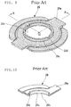
- FIG. 8 is a plan view of a side plate used in the self-aligning clutch release bearing device in FIG. 7 .
- FIG. 9 is a perspective view of the side plate used in the self-aligning clutch release bearing device in FIG. 7 .
- FIG. 10 is a sectional view taken in a line X-X in FIG. 9 .
- FIG. 11 is a plan view which shows a positional relationship between a fiber flow in a steel sheet and a cutout portion in the side plate when the side plate FIG. 8 is punched out of the steel sheet.
- the clutch release bearing device 20 is attached to a manual transmission 22 of an automobile or the like.
- the clutch release bearing device 20 is part of a clutch mechanism, which includes: a clutch device B placed in a power transmission path between an engine (output shaft 21 ) and the manual transmission 22 ; a retainer (front cover) 24 covering an input shaft of the transmission 22 ; a clutch release fork 23 that is pivoted interlocking with the operation of a clutch pedal (not illustrated); and the clutch release bearing device 20 .
- the clutch release bearing device 20 is axially amounted around the retainer 24 in a slidable fashion, and slides axially on the retainer 24 toward the engine to contact a diaphragm spring 31 of the clutch device B as the clutch release fork 23 pivots, whereby transmission of the engine rotation power to the transmission 22 is temporarily disengaged.
- the clutch release bearing device 20 includes: a release hub 1 ; a release bearing 2 which is fitted around the release hub 1 ; a generally disc-like side plate 3 to be contacted by the clutch release fork (not illustrated); an elastic member 4 which applies a predetermined axial load to the release bearing 2 ; and a cover 5 which holds the release hub 1 , the release bearing 2 , the side plate 3 and the elastic member 4 .
- the clutch release bearing device 20 is a self-aligning clutch release bearing device. If there is an axial alignment error between the engine axis and the transmission axis, the self-aligning clutch release bearing device 20 allows the release bearing 2 to slide radially as much as the amount of error to automatically correct the misalignment between the two axes.
- the release hub 1 is a sleeve which is axially slidable on the retainer 24 extended from the manual transmission 22 .
- the release hub 1 is cylindrical.
- the release hub 1 is made of an artificial thermoplastic resin such as PA (polyamide) 66 .
- the resin material for forming the release hub 1 may have enhancers, such as carbon fiber, mixed at a rate of 5 through 25 weight percent.
- the release bearing 2 includes an outer ring 6 , an inner ring 7 , a retainer 8 , and rolling elements 9 .
- the release bearing 2 is a ball bearing.
- the outer ring 6 is fitted around the release hub 1 with a predetermined radial gap thereto, and has an inner circumference formed with an outer rolling surface 6 a .
- the inner ring 7 which is fitted in the outer ring 6 , has an outer circumference formed with an inner rolling surface 7 a facing the outer rolling surface 6 a and extends radially outward. Between the rolling surface 6 a of the outer ring 6 and the rolling surface 7 a of the inner ring 7 , a plurality of rolling elements (balls) 9 are rollably retained by a retainer 8 .
- the outer ring 6 has its two ends provided with seals 10 , 11 .
- the seals 10 , 11 prevent lubrication grease packed inside the bearing from leaking outside while also preventing rain water, dust and other foreign matters from entering the bearing.
- the inner ring 7 is fitted around the release hub 1 , and makes contact with the diaphragm spring 31 of the clutch device B. At this occasion, deflection of the diaphragm spring 31 moves a pressure plate 34 , which presses the clutch disc 32 onto the flywheel 33 , away from the clutch disc 32 , whereby rotation power of the rotating output shaft 21 of the engine is temporarily disengaged from the transmission 22 .
- the side plate 3 is generally disc-shaped and is made by pressing a steel sheet.
- the material steel sheet for the side plate 3 is provided by a carburized steel sheet.
- the side plate 3 is made of a steel sheet C which is provided by an SCM (chromium molybdenum steel). Specifically, a predetermined shape is obtained from a cold rolled steel sheet of SCM by means of a pressing operation.
- SCM chromium molybdenum steel
- SCM steel has a higher surface hardness than SPCC steel and therefore is superior in terms of mechanical properties. For this reason, it is preferable to use a stronger SCM steel for the side plate 3 which is subjected to increased input load in recent years due to increased output from the engine.
- SCM steel is classified into a plurality of types according to its carbon content. Among these, SCM415 is the most preferable.
- the side plate 3 After being pressed into a predetermined shape, the side plate 3 may undergo a carbonitriding process for increased surface hardness. For example, the side plate 3 may undergo a carburizing and quenching process to attain a surface hardness of 54 through 64 HRC to reduce wearing of the side plate 3 from contact by the clutch release fork 23 .
- the side plate 3 is formed with a radially extending main body portion 3 a .
- the main body portion 3 a makes engagement with the clutch release fork and guide it.
- the side plate 3 is integrated with the release hub 1 , which is made of resin, by means of an insert molding.
- the main body portion 3 a has its inner diameter edge buried in the release hub 1 .
- the side plate 3 has a flange portion 3 c which extends from the inner diameter edge of the main body portion 3 a axially in one direction (toward the transmission 22 ).
- the flange portion 3 c is buried in the release hub 1 .
- the main body portion 3 a and the flange portion 3 c represent an inner diameter portion 3 b which is the portion buried in the release hub 1 .
- the flange portion 3 c is formed with cutout portions 3 d which prevent the side plate 3 from rotating relatively to the release hub 1 .
- the cutout portions 3 d are made at locations which will be described later. It should be noted here that the flange portion 3 c may extend from the inner diameter edges of the main body portion 3 a axially in the other direction (toward the engine).
- the elastic member 4 is, for example, a disc spring made by pressing a steel sheet.
- the elastic member 4 is provided by an open-ended ring which has a flat sections and a plurality, e.g., three to five, of waves, and is made of a steel wire (JIS SW or SWP series) by means of waving and rounding processes followed by heat treatment, i.e., stress relief annealing and subsequent age hardening.
- JIS SW or SWP series steel wire
- the cover 5 is made of a corrosion resistant steel sheet, such as a cold rolled steel (JIS SPCC series), and an austenitic stainless steel sheet (JIS SUS304 series), by means of pressing into a cylindrical shape to cover the release bearing 2 .
- the cover 5 has its one end portion formed with an inward flange 5 a for housing the elastic member 4 , and another end portion formed with tabs at a plurality of locations in circumferential direction. These tabs 5 b are crimped onto an outer diameter portion of the side plate 3 to hold the elastic member 4 , the outer ring 6 and the side plate 3 together in order to prevent the separation.
- the cover 5 Since the elastic member 4 does not slide against the inward flange 5 a of the cover 5 , the cover 5 does not have a chance for uneven wear. Therefore, it is possible to maintain a predetermined holding force and to hold the release bearing 2 at an alignment position for a long period of time.
- the release bearing 2 has its outer ring 6 elastically held by the elastic member 4 which is provided by an open-ended ring having a plurality of waves, whereas the release bearing 2 is fitted around the release hub 1 with a predetermined radial gap therefrom.
- the radial gaps S 1 , S 2 allow radial, self-aligning movement of the release bearing 2 relative to the release hub 1 and the side plate 3 , and the amount of movement is limited by the smaller radial gap S 2 . Therefore, in cases where there is an assembly error for example, between the axis of the release hub 1 and the axis of the output shaft 21 leading to misalignment between the rotation axis of the diaphragm spring 31 and the rotation axis of the clutch release bearing device 20 , the release bearing 2 moves accordingly to the amount of error, whereby the misalignment is automatically corrected.
- the side plate 3 used in the self-aligning clutch release bearing device 20 according to the present invention is integrated with the cylindrical, resin release hub 1 at the end of the hub opposed to the transmission (not shown) by means of insert molding.
- a generally disc-like piece is obtained from a SCM steel sheet C as a base piece for making the side plate 3 including the inner diameter portion 3 b . Then, a burring process is performed to an area surrounding the region which is to become the inner diameter portion 3 b (the inner diameter portion of the main body portion 3 a ), to form a flange portion 3 c.
- the flange portion 3 c in the side plate 3 is formed with cutout portions 3 d to prevent rotation when buried and fixed into the release hub 1 .
- locations for the cutout portions 3 d of the side plate 3 are selected with consideration into the direction of fiber flow in the steel sheet C.
- the cutout portions 3 d are provided at locations where an imaginary line V (alternate long and two short dashes lines in FIG. 2 and FIG. 5 ) which passes through the cutout portions 3 d and the center O of the side plate 3 (inner diameter portion 3 b ) is across the fiber flow which is drawn conceptually by fine lines, so that the cracks will not develop at the time of burring process. This makes it possible to prevent low yield from machining process of the side plate 3 , and also to ensure strength of the side plate 3 .
- V alternate long and two short dashes lines in FIG. 2 and FIG. 5
- FIG. 2 and FIG. 3 also show the direction of the fiber flow in fine lines in a conceptual fashion.
- the cutout portions 3 d are provided at locations where the imaginary line V which passes through the cutout portions 3 d and the center O of the inner diameter portion 3 b is across the fiber flow at an angle of 90 degrees.
- the angle at which the imaginary line V that passes through the cutout portions 3 d and the center O of the side plate 3 makes with the fiber flow is not limited to 90 degrees. Specifically, any angle in a range of 45 degrees through 90 degrees will be fine. However, a maximum strength improvement is obtained when the angle is 90 degrees as in the present embodiment.
Abstract
Description
-
- 1: Release hub
- 2: Release bearing
- 3: Side plate
- 3 a: Main body portion
- 3 b: Inner diameter portion
- 3 c: Flange portion
- 3 d: Cutout portion
- 4: Elastic member
- 5: Cover
- 5A: Inward flange
- 5 b: Tab
- 6: Outer ring
- 6 a: Outer rolling surface
- 7: Inner ring
- 7 a: Inner rolling surface
- 8: Retainer
- 9: Side plate
- 10, 11: Seal
- C: Steel sheet
Claims (4)
Applications Claiming Priority (4)
| Application Number | Priority Date | Filing Date | Title |
|---|---|---|---|
| JP2017130279A JP6449382B1 (en) | 2017-07-03 | 2017-07-03 | Clutch release bearing device |
| JPJP2017-130279 | 2017-07-03 | ||
| JP2017-130279 | 2017-07-03 | ||
| PCT/JP2018/022037 WO2019009011A1 (en) | 2017-07-03 | 2018-06-08 | Clutch release bearing device |
Publications (2)
| Publication Number | Publication Date |
|---|---|
| US20200116209A1 US20200116209A1 (en) | 2020-04-16 |
| US11215240B2 true US11215240B2 (en) | 2022-01-04 |
Family
ID=64950899
Family Applications (1)
| Application Number | Title | Priority Date | Filing Date |
|---|---|---|---|
| US16/624,243 Active 2038-06-20 US11215240B2 (en) | 2017-07-03 | 2018-06-08 | Clutch release bearing device |
Country Status (3)
| Country | Link |
|---|---|
| US (1) | US11215240B2 (en) |
| JP (1) | JP6449382B1 (en) |
| WO (1) | WO2019009011A1 (en) |
Citations (12)
| Publication number | Priority date | Publication date | Assignee | Title |
|---|---|---|---|---|
| US4029186A (en) * | 1975-03-21 | 1977-06-14 | Societe Anonyme Francaise Du Ferodo | Radially movable clutch release bearing |
| US4561788A (en) * | 1984-10-04 | 1985-12-31 | Nippon Seiko Kabushiki Kaisha | Clutch release bearing device |
| US4874073A (en) * | 1987-04-02 | 1989-10-17 | Nippon Seiko Kabushiki Kaisha | Clutch release bearing device |
| JPH0386349A (en) | 1989-08-29 | 1991-04-11 | Aichi Steel Works Ltd | Manufacture of ring-like forged product and device used to this |
| JPH09126290A (en) | 1995-10-30 | 1997-05-13 | Nissan Motor Co Ltd | Friction wheel for friction wheel type continuously variable transmission and manufacture thereof |
| JPH11270586A (en) * | 1998-03-20 | 1999-10-05 | Ntn Corp | Clutch release mechanism for automobile, and self-alignment type clutch release bearing device |
| JP2000055079A (en) | 1998-08-11 | 2000-02-22 | Ntn Corp | Self-aligning type clutch release bearing device |
| JP2005088668A (en) | 2003-09-16 | 2005-04-07 | Nsk Ltd | Rolling bearing unit for supporting wheel, and method for manufacturing the same |
| JP2006038159A (en) | 2004-07-29 | 2006-02-09 | Ntn Corp | Self-alignment clutch release bearing device |
| JP2006105323A (en) * | 2004-10-07 | 2006-04-20 | Ntn Corp | Ball bearing |
| JP2009068537A (en) | 2007-09-11 | 2009-04-02 | Ntn Corp | Clutch release bearing device |
| JP2009131874A (en) | 2007-11-30 | 2009-06-18 | Sanyo Special Steel Co Ltd | Method of manufacturing ring product having annular recessed groove on outside-diameter surface by conrolling fiber flow in form rolling |
-
2017
- 2017-07-03 JP JP2017130279A patent/JP6449382B1/en active Active
-
2018
- 2018-06-08 WO PCT/JP2018/022037 patent/WO2019009011A1/en active Application Filing
- 2018-06-08 US US16/624,243 patent/US11215240B2/en active Active
Patent Citations (13)
| Publication number | Priority date | Publication date | Assignee | Title |
|---|---|---|---|---|
| US4029186A (en) * | 1975-03-21 | 1977-06-14 | Societe Anonyme Francaise Du Ferodo | Radially movable clutch release bearing |
| US4561788A (en) * | 1984-10-04 | 1985-12-31 | Nippon Seiko Kabushiki Kaisha | Clutch release bearing device |
| US4874073A (en) * | 1987-04-02 | 1989-10-17 | Nippon Seiko Kabushiki Kaisha | Clutch release bearing device |
| JPH0386349A (en) | 1989-08-29 | 1991-04-11 | Aichi Steel Works Ltd | Manufacture of ring-like forged product and device used to this |
| US5976053A (en) | 1995-10-30 | 1999-11-02 | Nissan Motor Co., Ltd. | Method of manufacturing traction rollers for continuously variable transmissions and traction rollers resulting therefrom |
| JPH09126290A (en) | 1995-10-30 | 1997-05-13 | Nissan Motor Co Ltd | Friction wheel for friction wheel type continuously variable transmission and manufacture thereof |
| JPH11270586A (en) * | 1998-03-20 | 1999-10-05 | Ntn Corp | Clutch release mechanism for automobile, and self-alignment type clutch release bearing device |
| JP2000055079A (en) | 1998-08-11 | 2000-02-22 | Ntn Corp | Self-aligning type clutch release bearing device |
| JP2005088668A (en) | 2003-09-16 | 2005-04-07 | Nsk Ltd | Rolling bearing unit for supporting wheel, and method for manufacturing the same |
| JP2006038159A (en) | 2004-07-29 | 2006-02-09 | Ntn Corp | Self-alignment clutch release bearing device |
| JP2006105323A (en) * | 2004-10-07 | 2006-04-20 | Ntn Corp | Ball bearing |
| JP2009068537A (en) | 2007-09-11 | 2009-04-02 | Ntn Corp | Clutch release bearing device |
| JP2009131874A (en) | 2007-11-30 | 2009-06-18 | Sanyo Special Steel Co Ltd | Method of manufacturing ring product having annular recessed groove on outside-diameter surface by conrolling fiber flow in form rolling |
Non-Patent Citations (2)
| Title |
|---|
| English Translation of International Search Report of PCT/JP2018/022037 dated Aug. 21, 2018. |
| International Preliminary Report on Patentability including Written opinion of the International Searching Authority for International Application No. PCT/JP2018/022037 dated Jan. 16, 2020 and English translation thereof. |
Also Published As
| Publication number | Publication date |
|---|---|
| WO2019009011A1 (en) | 2019-01-10 |
| JP2019015292A (en) | 2019-01-31 |
| US20200116209A1 (en) | 2020-04-16 |
| JP6449382B1 (en) | 2019-01-09 |
Similar Documents
| Publication | Publication Date | Title |
|---|---|---|
| US20100189387A1 (en) | Rolling bearing | |
| US9816560B2 (en) | Seal ring-equipped ball bearing | |
| US20110303506A1 (en) | Clutch-Release Bearing Device including a Wear Ring | |
| KR101852698B1 (en) | Release bearing and clutch release bearing device | |
| US8475053B2 (en) | Inner ring and outer ring, and ball bearing | |
| GB2045380A (en) | Clutch release bearing assembly | |
| US9657785B2 (en) | Rolling bearing, notably for clutch release bearing device | |
| US4077504A (en) | Self-centering clutch thrust bearing | |
| US20120261227A1 (en) | Clutch-Release Bearing Device including a Wear Ring | |
| US4365850A (en) | Clutch thrust bearing unit with guided elastic self-alignment | |
| US11215240B2 (en) | Clutch release bearing device | |
| JP4552896B2 (en) | Shell roller bearing | |
| US20120263406A1 (en) | Rolling bearing, notably for a clutch release bearing device | |
| US20190162312A1 (en) | Bearing sealing device | |
| US3672736A (en) | Annular shield for bearings | |
| JP2004019731A (en) | Self-aligning roller bearing | |
| JP2005163943A (en) | Clutch release bearing | |
| JP3889167B2 (en) | Self-aligning clutch release bearing device | |
| CN108779812B (en) | Release bearing | |
| US11877899B2 (en) | Roller bearing | |
| GB2072789A (en) | A sliding sleeve for a clutch release bearing assembly | |
| GB2044385A (en) | Clutch Release Mechanisms | |
| JP6923468B2 (en) | Clutch release bearing device | |
| US9989106B2 (en) | Clutch release bearing device and motor vehicle equipped with such a bearing | |
| JP3648046B2 (en) | Self-aligning clutch release bearing device |
Legal Events
| Date | Code | Title | Description |
|---|---|---|---|
| AS | Assignment |
Owner name: NTN CORPORATION, JAPAN Free format text: ASSIGNMENT OF ASSIGNORS INTEREST;ASSIGNOR:FUKAMA, SHOHEI;REEL/FRAME:051325/0094 Effective date: 20191205 |
|
| FEPP | Fee payment procedure |
Free format text: ENTITY STATUS SET TO UNDISCOUNTED (ORIGINAL EVENT CODE: BIG.); ENTITY STATUS OF PATENT OWNER: LARGE ENTITY |
|
| STPP | Information on status: patent application and granting procedure in general |
Free format text: NON FINAL ACTION MAILED |
|
| STPP | Information on status: patent application and granting procedure in general |
Free format text: RESPONSE TO NON-FINAL OFFICE ACTION ENTERED AND FORWARDED TO EXAMINER |
|
| STPP | Information on status: patent application and granting procedure in general |
Free format text: FINAL REJECTION MAILED |
|
| STPP | Information on status: patent application and granting procedure in general |
Free format text: RESPONSE AFTER FINAL ACTION FORWARDED TO EXAMINER |
|
| STPP | Information on status: patent application and granting procedure in general |
Free format text: NOTICE OF ALLOWANCE MAILED -- APPLICATION RECEIVED IN OFFICE OF PUBLICATIONS |
|
| STPP | Information on status: patent application and granting procedure in general |
Free format text: PUBLICATIONS -- ISSUE FEE PAYMENT VERIFIED |
|
| STCF | Information on status: patent grant |
Free format text: PATENTED CASE |