US11214345B2 - Propulsion assembly and boat combination, boat propulsion method, and boat propulsion assembly - Google Patents
Propulsion assembly and boat combination, boat propulsion method, and boat propulsion assembly Download PDFInfo
- Publication number
- US11214345B2 US11214345B2 US16/659,953 US201916659953A US11214345B2 US 11214345 B2 US11214345 B2 US 11214345B2 US 201916659953 A US201916659953 A US 201916659953A US 11214345 B2 US11214345 B2 US 11214345B2
- Authority
- US
- United States
- Prior art keywords
- boat
- transom
- outboard
- engine
- plates
- Prior art date
- Legal status (The legal status is an assumption and is not a legal conclusion. Google has not performed a legal analysis and makes no representation as to the accuracy of the status listed.)
- Active
Links
Images


Classifications
-
- B—PERFORMING OPERATIONS; TRANSPORTING
- B63—SHIPS OR OTHER WATERBORNE VESSELS; RELATED EQUIPMENT
- B63H—MARINE PROPULSION OR STEERING
- B63H20/00—Outboard propulsion units, e.g. outboard motors or Z-drives; Arrangements thereof on vessels
- B63H20/08—Means enabling movement of the position of the propulsion element, e.g. for trim, tilt or steering; Control of trim or tilt
- B63H20/10—Means enabling trim or tilt, or lifting of the propulsion element when an obstruction is hit; Control of trim or tilt
- B63H20/106—Means enabling lifting of the propulsion element in a substantially vertical, linearly sliding movement
-
- B—PERFORMING OPERATIONS; TRANSPORTING
- B63—SHIPS OR OTHER WATERBORNE VESSELS; RELATED EQUIPMENT
- B63H—MARINE PROPULSION OR STEERING
- B63H20/00—Outboard propulsion units, e.g. outboard motors or Z-drives; Arrangements thereof on vessels
- B63H20/02—Mounting of propulsion units
- B63H20/06—Mounting of propulsion units on an intermediate support
-
- B—PERFORMING OPERATIONS; TRANSPORTING
- B63—SHIPS OR OTHER WATERBORNE VESSELS; RELATED EQUIPMENT
- B63H—MARINE PROPULSION OR STEERING
- B63H20/00—Outboard propulsion units, e.g. outboard motors or Z-drives; Arrangements thereof on vessels
- B63H20/02—Mounting of propulsion units
-
- B—PERFORMING OPERATIONS; TRANSPORTING
- B63—SHIPS OR OTHER WATERBORNE VESSELS; RELATED EQUIPMENT
- B63H—MARINE PROPULSION OR STEERING
- B63H20/00—Outboard propulsion units, e.g. outboard motors or Z-drives; Arrangements thereof on vessels
- B63H20/08—Means enabling movement of the position of the propulsion element, e.g. for trim, tilt or steering; Control of trim or tilt
Definitions
- Object of the present invention is a combination of a propulsion assembly and boat, a propulsion method of a boat and propulsion assembly for a boat.
- Purpose of the present invention is to improve the efficiency of marine engines, especially outboard, so that to allow the user to optimize the thrust effect with respect to the different speed and floating conditions and to the different shapes of the hull.
- the trim of the engines determines a variation in the orientation of the propellers which modify the direction of the thrust force by orienting such force more downwards or upwards.
- the vertical translation obtained thanks to motorized sleds named jack-plates which are interposed between the transom of the boat and the engine, determine the position of the propellers with respect to the surface of the water, i.e. their degree of draught and also the position of the propellers with respect to the lower edge of the transom.
- the quantity of water wetting the propeller is not uniform and strongly depends on the distance of the engine from the transom. This involves a non-optimal adjustment of the vertical position of the engines.
- Applicant has found that similar benefits of optimizing the position of the engine or of two or more engines can be obtained by means of a purely mechanical device which, consisting of simple, inexpensive and easy to implement elements, is able to optimize the use of the propulsive thrust of one or more engines without however introducing undesired implementation complications.
- Object of the present invention is to optimize the propulsive thrust of a boat while allowing to position the outboard engine or engines, i.e. the corresponding propellers, in a position with respect to the hull, in particular at the keel thereof, and at the surface of the water such as to maximize the performance of the boat according to the needs of the speed selected and to the maneuvers to carry out.
- the outboard engine or engines i.e. the corresponding propellers
- the invention achieves the objective with a combination of a boat and outboard engine, wherein at least one outboard engine is fastened to the transom of said boat at a prearranged position, said engine being mounted so that to translate along a path with at least one motion component having a vertical orientation in a direction away from or close to the waterline of the boat, i.e. of smaller or greater propeller draft, and a motion component having a horizontal or longitudinal orientation in a direction away from or close to the transom of the boat.
- vertical translation or vertical component of translation or displacement refers to a displacement in a direction perpendicular to the floating plane of reference of the boat.
- horizontal translation or horizontal component of translation or of displacement refers to a displacement in a direction parallel to the longitudinal axis of the boat, i.e. perpendicular to the main section of the boat.
- the engine does not lose pressure because it is positioned at a certain distance from the transom in the zone in which the flow of water reaches a higher level.
- the engine is translated along a direction belonging to a plane perpendicular to the main section or parallel to a sectional longitudinal plane of the hull of the boat.
- the translation of the engine occurs along a straight displacement path so that a translation away from the transom of the engine is combined with a vertical translation in direction of smaller propeller draft.
- the displacement in a direction away from the transom is gradual and increasing on the basis of the increase of the vertical displacement in the direction of smaller propeller draft.
- the translation of the engine is driven, for example, by fastening devices to fasten the engine to the transom with displacement actuators of the mechanical, electric, hydraulic, electro-hydraulic, electromechanical, magnetic type.
- the fastening devices to fasten the engine to the transom can advantageously comprise a couple of plates, of which one is fixed and one is movable, the plates acting like a sled one on the other, the movable plate sliding on the fixed plate along a plane parallel to a sectional longitudinal plane of the hull or perpendicular to the main section of the boat.
- the fastening system to fasten the engine to the transom is constituted by a four-bar linkage or articulated polygon whose arms are of invariable length.
- control of the displacement of the engine is advantageously entrusted to a control unit configured to drive the displacement actuators so that to translate the engine in a direction away from the transom when said engine is translated vertically in a direction away from the waterline surface, i.e. of smaller propeller draft.
- the invention concerns a method of governing a boat, comprising one, two or more outboard engines, the method providing the displacement of at least one of said engines along a path with at least one motion component having a vertical orientation in a direction away from or close to the waterline of the boat and a motion component having a horizontal or longitudinal orientation in a direction away from or close to the transom of the boat.
- the displacement of the engine or engines occurs on a plane perpendicular to the main section or parallel to the longitudinal symmetry plane of the boat, by combining two linear translations along two directions that are not parallel to one another, preferably perpendicular to one another, for example one being a translation along a direction parallel to the longitudinal axis of the hull and the other one being a translation along a vertical direction.
- the translation on the plane perpendicular to the main section or parallel to the symmetry plane i.e. perpendicular to the transom or to one of its tangents, occurs along a path corresponding to a straight line.
- the displacement of the engine or engines in a direction away from the transom is gradual and increasing on the basis of the increase of the vertical displacement in the direction of smaller propeller draft.
- the displacement of the engine or engines can be provided in combination with the steering rotation of the engine or engines and/or with a trim inclination of the engine or engines and/or with a translation towards a broadside of the hull of the engine or engines.
- the invention concerns a propulsion assembly for a boat, comprising at least one outboard engine or two or more outboard engines, fastening devices to fasten the outboard engine or engines and which allow the displacements of the outboard engine or engines along predefined paths thanks to displacement actuators and wherein a drive system to drive the activating actuators of said devices is provided.
- the control system provides at least one drive member operable by the user and at least one control unit adapted to receive the drive signals generated by the drive member and to transform said signals into power signals adapted to supply the actuators correspondingly to said signals generated by the drive members.
- the control unit is advantageously programmed to drive the displacement actuators so that to translate the engine in a direction away from the transom whenever said engine is translated vertically in a direction away from the waterline surface, i.e. of smaller propeller draft.
- control unit is programmed to drive the displacement actuators so that to translate the engine in a direction away from the transom, gradually and increasingly on the basis of the increase of the vertical movement in the direction of smaller propeller draft.
- FIG. 1 schematically shows a boat provided with an outboard engine with the waterline denoted by the dotted line.
- FIG. 2 schematically shows a side view of a boat provided with an engine that can translate vertically, thanks to the use of so-named jack-plates of the traditional type.
- FIG. 3 schematically shows a side view of a boat according to an embodiment of the invention, wherein the engine can translate both vertically and longitudinally and anyhow along two tilted directions in a plane parallel to the longitudinal symmetry plane of the boat.
- FIG. 4 schematically shows the position assumed by an engine with respect to the transom in the configuration of maximum (top) and minimum (bottom) propeller draft limit with reference to a configuration with traditional jack-plates (left), bracket holder with a four-bar linkage configuration (middle) and with a fastening device according to the invention (right).
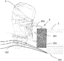
- FIG. 5 schematically shows a side view of a boat provided with a plate-like fastening device adapted to allow the translation of the engine in an oblique direction belonging to a plane parallel to the longitudinal symmetry plane of the boat.
- FIG. 6 schematically shows a plan view of the fastening device of the preceding figure.
- a boat comprises a hull 1 with a transom 101 .
- An outboard engine 2 is fastened to the transom 101 in a central position.
- the engine 2 is considered mounted so that to be able to carry out all possible displacements with respect to the transom currently known at the state of the art and, in particular, the steering rotation, trim inclination and vertical translation.
- each displacement of one or more engines can further be combined with one or more of the aforesaid displacements known at the state of the art and, in particular, always with a steering rotation of the engine or engines and optionally with one trim displacement.
- the invention provides that, in addition to the steering rotation of the engine, the engine is further translatable along a direction with at least one motion component having a vertical orientation in a direction away from or close to the waterline of the boat, i.e. of smaller or greater propeller draft, and a motion component having a horizontal or longitudinal orientation in a direction away from or close to the transom of the boat.
- An embodiment provides that the engine or engines can be displaced relatively to the transom along a vertical plane parallel to a sectional longitudinal plane of the hull of the boat, as shown in FIG. 5 .
- the displacement in said plane can occur by combining two linear translations along to two directions that are not parallel to one another, preferably perpendicular, for example a longitudinal and a vertical translation.
- one of the two translations i.e. the longitudinal one, is along an axis parallel to the waterline and the other one being along an axis perpendicular to the waterline.
- waterline means the substantially horizontal plane containing the theoretical waterline of the project of the boat.
- the two translations along two directions perpendicular to one another can be actuated thanks to a combination of translation sleds of which a first sled is mounted on sliding guides along a supporting plate 301 so that to translate along a first of the two translation directions and a second sled is mounted on the first sled by means of guides of relative translation with respect to said first sled, which are oriented so that to allow the translation of said second sled in the second translation direction, while the engine is mounted on a movable plate 403 integral with the second sled and the supporting plate 301 is fastened to the transom 101 .
- Each of the sleds is slidingly driven by means of an actuator which can be of any type and interfaced with a control unit (identified with reference number 6 in FIG. 1 ) advantageously configured to drive the displacement actuators so that to translate the engine in a direction away from the transom when said engine is translated vertically in a direction away from the waterline surface, i.e. of smaller propeller draft.
- an actuator which can be of any type and interfaced with a control unit (identified with reference number 6 in FIG. 1 ) advantageously configured to drive the displacement actuators so that to translate the engine in a direction away from the transom when said engine is translated vertically in a direction away from the waterline surface, i.e. of smaller propeller draft.
- FIG. 6 schematically shows a motorized-sled fastening device that can be used to achieve the translations of the engine or engines according to the invention.
- the device denoted by the reference 3 , provides a supporting plate 403 for supporting the engine 2 which has, on the side facing outwardly, a couple of guides formed by vertical ribs 503 spaced from one another so that to form a sliding groove for a sliding block 603 integral with a second plate 303 constituting a further sliding sled.
- the guides are oriented in a direction perpendicular to the waterline and the supporting plate 403 moves with respect to the intermediate sled 303 in said upwards and downwards direction.
- the intermediate sled 303 in turn bears a couple of guides 203 substantially similar to guides 503 .
- the guides 203 are oriented in a direction parallel to a sectional longitudinal plane, i.e. in a direction perpendicular to the guides 503 , and respective sliding skates 103 , which are integral with a further plate 301 fastened to the transom, slide therein.
- the device 3 allows a displacement of the engine both in longitudinal and vertical direction so that to move it away from the transom when it is raised upwards, thus increasing the water pressure.
- the water flow leaving the keel 201 of a boat in fact has a substantially parabolic pattern with concavity facing downwards and vertex arranged at a certain distance from the transom 101 .
- the engine in addition to being translated upwards, is also displaced backwards, i.e. in a direction away from the transom as shown in FIG. 3 , at the same height of the engine, the point A is well under the last fluid fillet B with the propeller 102 completely immersed since located in the zone wherein the water flow has a maximum. This provides the ability to further raise the engine without losing pressure.
- FIG. 4 Three engines in the same draft situation are shown in the upper part.
- the top left figure relates to a jack-plates system of the traditional type, i.e. with adjustment only along the vertical direction.
- the central figure is related to a fastening by means of a bracket holder with a four-bar linkage configuration.
- the top right figure instead relates to a fastening according to the invention and which allows the engine to translate in a sectional longitudinal plane of the boat along an oblique direction, i.e. along a straight line with both vertical and horizontal components.
- the figures below show the draft limit position of the propellers following an upwards engine travel for each configuration.
- the traditional jack-plate rigidly translates the engine upwards, while keeping the distance from the transom constant.
- the bracket holder makes the engine carry out a movement along an arc of a circle with an initial moving away from the transom and a successive moving closer again when the rectangular configuration is exceeded, with an overall moving closer to the transom of the quantity denoted by d.
- the engine translates upwards concurrently with a movement away from the transom to place itself at a distance D therefrom. The result is that the maximum height reachable before the cavitation is minimum with a bracket holder, intermediate with a traditional jack-plate and maximum in the present invention.
- the invention lends to numerous embodiment variants. For example, it is possible to provide any mechanism for supporting the engines which allows their displacement relatively to the transom along different axes of translation and rotation.
- the configuration of these mechanisms is also of any type as along as it is possible to operate a translation away from or close to the transom concurrently with a vertical translation.
- the drive members of the displacement of the engine or engines can be of any type, such as for example a Joystick (identified with reference number 5 in FIG. 1 ) or a button or a combination thereof. All without departing from the guiding principle afore described and claimed hereinbelow.
Landscapes
- Chemical & Material Sciences (AREA)
- Engineering & Computer Science (AREA)
- Combustion & Propulsion (AREA)
- Mechanical Engineering (AREA)
- Ocean & Marine Engineering (AREA)
- Cylinder Crankcases Of Internal Combustion Engines (AREA)
- Compositions Of Oxide Ceramics (AREA)
- Earth Drilling (AREA)
- Ceramic Products (AREA)
- Output Control And Ontrol Of Special Type Engine (AREA)
Abstract
Description
Claims (12)
Applications Claiming Priority (2)
| Application Number | Priority Date | Filing Date | Title |
|---|---|---|---|
| IT102018000009660 | 2018-10-22 | ||
| IT102018000009660A IT201800009660A1 (en) | 2018-10-22 | 2018-10-22 | Combination of a propulsion group and a boat, a propulsion method of a boat and a propulsion group for a boat |
Publications (2)
| Publication Number | Publication Date |
|---|---|
| US20200130799A1 US20200130799A1 (en) | 2020-04-30 |
| US11214345B2 true US11214345B2 (en) | 2022-01-04 |
Family
ID=65244477
Family Applications (1)
| Application Number | Title | Priority Date | Filing Date |
|---|---|---|---|
| US16/659,953 Active US11214345B2 (en) | 2018-10-22 | 2019-10-22 | Propulsion assembly and boat combination, boat propulsion method, and boat propulsion assembly |
Country Status (3)
| Country | Link |
|---|---|
| US (1) | US11214345B2 (en) |
| EP (1) | EP3643598B1 (en) |
| IT (1) | IT201800009660A1 (en) |
Families Citing this family (4)
| Publication number | Priority date | Publication date | Assignee | Title |
|---|---|---|---|---|
| IT202100005582A1 (en) | 2021-03-10 | 2022-09-10 | Ultraflex Spa | SUPPORT SYSTEM FOR OUTBOARD MARINE ENGINES AT THE TRANSOM OF A BOAT |
| BR102021011518A2 (en) * | 2021-06-14 | 2022-12-27 | Jorge Sotirios Ghinis | ARTICULATED SUPPORT FOR FIXING OUTBOARD ENGINE IN NAUTICAL VEHICLES |
| JP2023037889A (en) * | 2021-09-06 | 2023-03-16 | ヤマハ発動機株式会社 | System and method for controlling behavior of vessel |
| RU2771107C1 (en) * | 2021-10-13 | 2022-04-26 | Владимир Викторович Михайлов | Automatic suspension of boat motor and method for operation of automatic suspension of boat motor |
Citations (6)
| Publication number | Priority date | Publication date | Assignee | Title |
|---|---|---|---|---|
| US2808218A (en) * | 1955-07-29 | 1957-10-01 | John M Steller | Outboard motor mountings |
| US4239172A (en) * | 1979-05-25 | 1980-12-16 | Gordon Spitzmesser | Engine mount for marine craft |
| US5186666A (en) | 1991-12-06 | 1993-02-16 | Stanley Thomas R | Marine motor drive unit mounting apparatus |
| WO1999022989A1 (en) | 1997-11-03 | 1999-05-14 | Lee Richards | Omni-directional horizontal thrust adjustable marine propulsion system |
| US6132271A (en) * | 1999-07-09 | 2000-10-17 | Hebert; Dana | Jack plate for vertical and aft placement of an outboard motor |
| US20170320554A1 (en) | 2016-05-05 | 2017-11-09 | Ultraflex S.P.A. | Combination of propulsion group and marine vessel, propulsion method of a marine vessel, and propulsion group for marine vessel |
-
2018
- 2018-10-22 IT IT102018000009660A patent/IT201800009660A1/en unknown
-
2019
- 2019-10-22 US US16/659,953 patent/US11214345B2/en active Active
- 2019-10-22 EP EP19204528.4A patent/EP3643598B1/en active Active
Patent Citations (7)
| Publication number | Priority date | Publication date | Assignee | Title |
|---|---|---|---|---|
| US2808218A (en) * | 1955-07-29 | 1957-10-01 | John M Steller | Outboard motor mountings |
| US4239172A (en) * | 1979-05-25 | 1980-12-16 | Gordon Spitzmesser | Engine mount for marine craft |
| US5186666A (en) | 1991-12-06 | 1993-02-16 | Stanley Thomas R | Marine motor drive unit mounting apparatus |
| WO1999022989A1 (en) | 1997-11-03 | 1999-05-14 | Lee Richards | Omni-directional horizontal thrust adjustable marine propulsion system |
| US6132271A (en) * | 1999-07-09 | 2000-10-17 | Hebert; Dana | Jack plate for vertical and aft placement of an outboard motor |
| US20170320554A1 (en) | 2016-05-05 | 2017-11-09 | Ultraflex S.P.A. | Combination of propulsion group and marine vessel, propulsion method of a marine vessel, and propulsion group for marine vessel |
| US10322784B2 (en) * | 2016-05-05 | 2019-06-18 | Ultraflex S.P.A. | Combination of propulsion group and marine vessel, propulsion method of a marine vessel, and propulsion group for marine vessel |
Non-Patent Citations (1)
| Title |
|---|
| Ministry of Economic Development (Italy), Search Report, dated May 28, 2019 See pages in English. |
Also Published As
| Publication number | Publication date |
|---|---|
| EP3643598B1 (en) | 2021-11-24 |
| IT201800009660A1 (en) | 2020-04-22 |
| EP3643598A1 (en) | 2020-04-29 |
| US20200130799A1 (en) | 2020-04-30 |
Similar Documents
| Publication | Publication Date | Title |
|---|---|---|
| US11214345B2 (en) | Propulsion assembly and boat combination, boat propulsion method, and boat propulsion assembly | |
| US20240149989A1 (en) | Variable trim deflector system and method for controlling a marine vessel | |
| US20220363359A1 (en) | System and method for controlling a marine vessel | |
| US4977845A (en) | Boat propulsion and handling system | |
| KR102294943B1 (en) | Watercraft having movable hydrofoils | |
| US2387907A (en) | Craft of the hydroplane type | |
| US7316595B2 (en) | Propeller positioning system which constrains the propeller to follow a path generally parallel to the bottom surface of a boat | |
| US20140224166A1 (en) | Variable trim deflector system with protruding foil and method for controlling a marine vessel | |
| US20240166325A1 (en) | System for controlling marine craft with steerable propellers | |
| CN101484353B (en) | Ship with bow control surface | |
| US4827862A (en) | Aerodynamic control system for high speed motorboats | |
| US3371642A (en) | Trim control device for boats | |
| US9809290B2 (en) | System and apparatus for outboard watercraft trim control | |
| US3081729A (en) | Marine craft and control apparatus therefor | |
| WO2020017069A1 (en) | Ship | |
| EP3411287B1 (en) | Catamaran craft | |
| JP7448235B2 (en) | Marine rudders and vessels | |
| US20250115345A1 (en) | Rudder to decrease drag and increase turning efficiency of a fluid traversing air and water craft | |
| KR20260031890A (en) | Apparatus for controlling flap of hydrofoil ship | |
| GB2454877A (en) | A watercraft with buoyant hydrofoil vanes | |
| JP5016933B2 (en) | Outboard propulsion system | |
| KR20250109299A (en) | Convertible type hydrofoil and ship including the same | |
| US996738A (en) | Boat. | |
| EP0421958A2 (en) | High-speed hydrohull | |
| AU2020377412A1 (en) | Assisted turning-heel steering |
Legal Events
| Date | Code | Title | Description |
|---|---|---|---|
| FEPP | Fee payment procedure |
Free format text: ENTITY STATUS SET TO UNDISCOUNTED (ORIGINAL EVENT CODE: BIG.); ENTITY STATUS OF PATENT OWNER: SMALL ENTITY |
|
| FEPP | Fee payment procedure |
Free format text: ENTITY STATUS SET TO SMALL (ORIGINAL EVENT CODE: SMAL); ENTITY STATUS OF PATENT OWNER: SMALL ENTITY |
|
| AS | Assignment |
Owner name: ULTRAFLEX S.P.A., ITALY Free format text: ASSIGNMENT OF ASSIGNORS INTEREST;ASSIGNORS:GAI, MARCELLA;CAMPAGNA, MARCO;REEL/FRAME:051196/0806 Effective date: 20191127 |
|
| STPP | Information on status: patent application and granting procedure in general |
Free format text: NON FINAL ACTION MAILED |
|
| STPP | Information on status: patent application and granting procedure in general |
Free format text: RESPONSE TO NON-FINAL OFFICE ACTION ENTERED AND FORWARDED TO EXAMINER |
|
| STPP | Information on status: patent application and granting procedure in general |
Free format text: NOTICE OF ALLOWANCE MAILED -- APPLICATION RECEIVED IN OFFICE OF PUBLICATIONS |
|
| STPP | Information on status: patent application and granting procedure in general |
Free format text: PUBLICATIONS -- ISSUE FEE PAYMENT RECEIVED |
|
| STPP | Information on status: patent application and granting procedure in general |
Free format text: PUBLICATIONS -- ISSUE FEE PAYMENT VERIFIED |
|
| STCF | Information on status: patent grant |
Free format text: PATENTED CASE |
|
| MAFP | Maintenance fee payment |
Free format text: PAYMENT OF MAINTENANCE FEE, 4TH YR, SMALL ENTITY (ORIGINAL EVENT CODE: M2551); ENTITY STATUS OF PATENT OWNER: SMALL ENTITY Year of fee payment: 4 |