US11213724B2 - Offset golf club head - Google Patents
Offset golf club head Download PDFInfo
- Publication number
- US11213724B2 US11213724B2 US16/548,760 US201916548760A US11213724B2 US 11213724 B2 US11213724 B2 US 11213724B2 US 201916548760 A US201916548760 A US 201916548760A US 11213724 B2 US11213724 B2 US 11213724B2
- Authority
- US
- United States
- Prior art keywords
- club
- club head
- golf
- golf club
- clubhead
- Prior art date
- Legal status (The legal status is an assumption and is not a legal conclusion. Google has not performed a legal analysis and makes no representation as to the accuracy of the status listed.)
- Active
Links
Images


Classifications
-
- A—HUMAN NECESSITIES
- A63—SPORTS; GAMES; AMUSEMENTS
- A63B—APPARATUS FOR PHYSICAL TRAINING, GYMNASTICS, SWIMMING, CLIMBING, OR FENCING; BALL GAMES; TRAINING EQUIPMENT
- A63B53/00—Golf clubs
- A63B53/02—Joint structures between the head and the shaft
-
- A—HUMAN NECESSITIES
- A63—SPORTS; GAMES; AMUSEMENTS
- A63B—APPARATUS FOR PHYSICAL TRAINING, GYMNASTICS, SWIMMING, CLIMBING, OR FENCING; BALL GAMES; TRAINING EQUIPMENT
- A63B53/00—Golf clubs
- A63B53/007—Putters
-
- A—HUMAN NECESSITIES
- A63—SPORTS; GAMES; AMUSEMENTS
- A63B—APPARATUS FOR PHYSICAL TRAINING, GYMNASTICS, SWIMMING, CLIMBING, OR FENCING; BALL GAMES; TRAINING EQUIPMENT
- A63B53/00—Golf clubs
- A63B53/04—Heads
-
- A—HUMAN NECESSITIES
- A63—SPORTS; GAMES; AMUSEMENTS
- A63B—APPARATUS FOR PHYSICAL TRAINING, GYMNASTICS, SWIMMING, CLIMBING, OR FENCING; BALL GAMES; TRAINING EQUIPMENT
- A63B53/00—Golf clubs
- A63B53/04—Heads
- A63B53/0466—Heads wood-type
-
- A—HUMAN NECESSITIES
- A63—SPORTS; GAMES; AMUSEMENTS
- A63B—APPARATUS FOR PHYSICAL TRAINING, GYMNASTICS, SWIMMING, CLIMBING, OR FENCING; BALL GAMES; TRAINING EQUIPMENT
- A63B53/00—Golf clubs
- A63B53/04—Heads
- A63B53/0487—Heads for putters
-
- A—HUMAN NECESSITIES
- A63—SPORTS; GAMES; AMUSEMENTS
- A63B—APPARATUS FOR PHYSICAL TRAINING, GYMNASTICS, SWIMMING, CLIMBING, OR FENCING; BALL GAMES; TRAINING EQUIPMENT
- A63B60/00—Details or accessories of golf clubs, bats, rackets or the like
- A63B60/02—Ballast means for adjusting the centre of mass
-
- A—HUMAN NECESSITIES
- A63—SPORTS; GAMES; AMUSEMENTS
- A63B—APPARATUS FOR PHYSICAL TRAINING, GYMNASTICS, SWIMMING, CLIMBING, OR FENCING; BALL GAMES; TRAINING EQUIPMENT
- A63B60/00—Details or accessories of golf clubs, bats, rackets or the like
- A63B60/40—Details or accessories of golf clubs, bats, rackets or the like having holding means provided inside, on the edge or on the rear face of the striking surface
-
- A—HUMAN NECESSITIES
- A63—SPORTS; GAMES; AMUSEMENTS
- A63B—APPARATUS FOR PHYSICAL TRAINING, GYMNASTICS, SWIMMING, CLIMBING, OR FENCING; BALL GAMES; TRAINING EQUIPMENT
- A63B53/00—Golf clubs
- A63B53/04—Heads
- A63B2053/0491—Heads with added weights, e.g. changeable, replaceable
-
- A—HUMAN NECESSITIES
- A63—SPORTS; GAMES; AMUSEMENTS
- A63B—APPARATUS FOR PHYSICAL TRAINING, GYMNASTICS, SWIMMING, CLIMBING, OR FENCING; BALL GAMES; TRAINING EQUIPMENT
- A63B2102/00—Application of clubs, bats, rackets or the like to the sporting activity ; particular sports involving the use of balls and clubs, bats, rackets, or the like
- A63B2102/32—Golf
Definitions
- the present invention generally relates to golf clubs used both recreationally and professionally.
- the current invention represents an improved design for club heads.
- golf club is a well-known competitive sport and improvements in golf club and golf ball technology represent a curiosity among both professionals and hobbyists. Indeed, golf is considered a difficult and competitive sport/hobby for many people. Many proposals have been made to design golf clubs which provide improved control over, and feel for, the golf ball, for example by providing grooves on the impact face of the golf club head. When your average golfer swings a golf club, he or she may have dramatic variations in his or her golf swing, resulting in numerous off-center hits, which result in diminished performance when compared to a direct center hit. However, in an attempt to make this very difficult game more enjoyable for the average golfer, golf club designers have come up with unique golf club designs that will mitigate the harsh realities of a less than perfect golf swing.
- U.S. Pat. No. 723,534 ('534 Patent), issued to Knight, describes a golf club in which the center of the shaft is connected to the head forward of the center mass in the direction of delivery of the blow and at a point between the heel and toe of the club-head. It comprises also a head having a striking face along its major axis, with the shaft connection at a point forward of the center of mass.
- U.S. Pat. No. 4,330,128 ('128 Patent), issued to Morelli, describes a golf putter having, in combination, a putting head and an elongate article, such as a bottle, a portion of which constitutes the putting surface.
- the putter comprises a generally flat, vertically oriented driving element attached to the putter shaft, with an aperture formed in the driving element of sufficient dimension to accept the elongate article.
- a receptor spaced from the driving element by an arm extending between the receptor and the driving element, is shaped to engage one end of the elongate article and retain the article with part of the article being situated within the aperture. That portion of the elongate article extending from the aperture on the side of the driving element opposite from the receptor constitutes the putting surface.
- U.S. Pat. No. 8,480,515 ('515 Patent), which issued to Roach et el., describes a golf club head having a translucent insert disclosed.
- the club head includes a body defining a striking face, a top line, a sole, a back, a heel, and a toe.
- the back contains a cavity that extends in a direction substantially perpendicular to the face.
- a recess is provided within the cavity, with the recess extending away from the cavity and toward the sole.
- a translucent insert such as a vibration dampening member, may be provided within the recess.
- the insert may contain secondary inserts, such as weight members, therein in strategic locations. The insert may completely fill the recess, or may fill only a portion thereof.
- United States Patent Application No. 2011/0014992 submitted by Morrissey, describes a golf club which includes a head and a shaft coupled to the head.
- the shaft is positioned so that an axis of the shaft intersect at or near a center of mass of the head.
- clubhead/shaft connection will allow for a golf club head that is a full rectangular shape rather than the currently used tear drop shape.
- This rectangular shape provides a larger striking area that has a concentrated center point of force, rather than an off-center, remote point of force.
- the disclosure contemplates a golf club including a shaft; and a clubhead, the clubhead having a body, a front face, and a back face, the shaft connected to the clubhead at the center of the back face by a connecting member, the connecting member extending away from the back face of the clubhead and turning to connect to the shaft; and wherein the front face of the clubhead forms a rectangular shape.
- the disclosure contemplates a golf club head including a body, a front face, a back face, and a connecting member; the connecting member attached to the center of the back face and extending away from the back face of the club head and turning at an angle; and wherein the front face of the clubhead forms a rectangular shape.
- the disclosure contemplates a golf club, including a shaft; and a body including: a ball striking face; a back face defined in the body at a location behind the ball striking face; a connection point extending in a direction away from the back face, wherein the connection point is connected to the center of mass of the body; wherein the connection point turns upwards and connects to the shaft; the striking face adapted for striking a ball.
- FIG. 1 is a front view of a club head and connection of the golf club head to the shaft.
- FIG. 2 is an angled view of the club head of FIG. 1 .
- FIG. 3 is a front view of a rectangular golf club head as described in the present disclosure.
- FIG. 4 is a top angled view of a golf club head of FIG. 3 as described in the present disclosure.
- FIG. 5 is front perspective view of a second embodiment of a rectangular golf club head as described in the present disclosure.
- FIG. 6 is a back side perspective view of the golf club head of FIG. 5 .
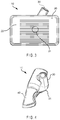
- FIG. 7 is a is a cross-sectional view in a horizontal plane at about the center of the head of another embodiment of a golf club head according to this disclosure.
- FIG. 8 is a back view of the club head of FIG. 7 .
- FIG. 9 is a cross sectional view of the golf club head of FIGS. 7 &8 .
- FIG. 10 is a side on, semi-transparent view of another embodiment of a gold club head according to the present disclosure.
- FIG. 11 is a front view of the golf club head of FIG. 10 .
- the present invention essentially provides an improved golf club and golf club heads.
- the preferred embodiments of the present invention will now be described with reference to FIGS. 1-11 of the drawings. Variations and embodiments contained herein will become apparent in light of the following descriptions.
- FIGS. 1 & 2 a more traditional form of golf club is depicted.
- a golfer addresses the golf ball, his endeavor is to locate the strike zone of the club head and golf ball as close to the bulge of the club shaft connection as possible in order to gain as much benefit if the golfer's swing as possible. Any slight modification of the golfer's swing will result in the golf ball striking the club shaft mounting as (at circles “A”) or striking the ball at the flag end of the club head (circles “B”). Striking the golf ball at either circle “A” or circle “B” will result in ball flight off-course of landing in a less desirable location.
- FIGS. 3 . & 4 A first embodiment of a club 10 according to the present disclosure is show.
- Club 10 is a replacement for traditional “irons” used by golfers.
- This club 10 connects clubhead 20 to shaft 30 at the center of the clubhead 21 at connection point 31 .
- this new design results in the clubhead ( 20 ) taking the shape of a rectangle as shown in FIG. 3 connecting the club shaft 30 to the center of the rear (at 31 ) of the clubhead 20 , results in a club face 22 without any obstruction allowing the ball flight direction to be more in the control of the golfer.
- the top face 40 of the embodiment is contoured to improve performance, by shifting the center of mass and changing the total mass of the clubhead 20 .
- This shape is substantially similar to a curved “E” as depicted with the club shaft passing between two of the “E'”s prongs.
- FIGS. 5 . & 6 a second embodiment of a club 100 , according to the present disclosure, is show.
- Club 100 is a similar to club 10 in that it also is a replacement for traditional “irons” used by golfers.
- This club 100 connects clubhead 120 to shaft 130 at the center of the clubhead 121 at connection point 131 . This results in the full power of the golfer's swing being transmitted directly to a golf ball resulting in a longer flight.
- this new design results in the clubhead 120 taking the shape of a square as shown in FIG.
- club 10 is shown as a rectangle and club 100 as a square, both can be adapted to use either a square or rectangular clubface, depending on the desired performance of the club.
- club 300 is a replacement for traditional “woods” used by golfers.
- This club 300 connects clubhead 320 to shaft 330 at the center of the clubhead 321 at connection point 3331 .
- this new design results in the clubhead 120 being supported by additional support or weight assembly 340 .
- the weight assembly 340 encompassing the connection point 331 at all sides and extending away from the back side towards the shaft 330 .
- the club shaft 330 remains connected to the center of the rear (at 331 ) of the clubhead 320 .
- club 10 is shown as a rounded rectangle it can be adapted to both square and rectangle configurations.
- connection point ( 231 , 331 ) may be substantially tapered, or it may be more uniform in thickness as shown in FIGS. 4 & 6 . Tapering of connection points can provide additional strength, but is not desirable in every application.
- the newly designed clubheads result in a flat faced club head which does not have a protrusion on one end near where the golf ball is struck or the end remote from the source of power of the golfer's swing, all affecting the direction of the golf ball flight head strike.
- the grasses are higher than the golf ball, to very high resulting in a very difficult shot.
- This hazard, the “rough”, provides great resistance to current club designs. This resistance from the taller grasses causes the flag end of the golf club to retreat, thereby affecting the flight direction of the golf ball.
- this problem can be at least partially overcome by the greater force and stability provided by the clubs disclosed herein.
Abstract
Description
-
- Turning now to
FIGS. 7, 8 , & 9. aclub 200, according to the present disclosure, is show.Club 200 is a replacement for traditional “putters” used by golfers. Thisclub 200 connects clubhead 220 toshaft 230 at the center of the clubhead 221 atconnection point 231. In this application, it typically will provide greater control and stability when striking the ball compared to traditional putters. In this way clubface 222 is less likely to turn on impact unless so directed by the golfer.Club 200 is typically constructed as a rectangle, with supportive backing orweight assembly 240. Said weight assembly angles from the top of the backside of the clubhead 220 towardsconnection point 231 and forms a curved triangle from the topside view and a shape from the backside view (as seen inFIGS. 7 & 8 ).
- Turning now to
Claims (4)
Priority Applications (1)
| Application Number | Priority Date | Filing Date | Title |
|---|---|---|---|
| US16/548,760 US11213724B2 (en) | 2017-02-15 | 2019-08-22 | Offset golf club head |
Applications Claiming Priority (3)
| Application Number | Priority Date | Filing Date | Title |
|---|---|---|---|
| US201762459365P | 2017-02-15 | 2017-02-15 | |
| US15/897,329 US10493330B2 (en) | 2017-02-15 | 2018-02-15 | Offset golf club head |
| US16/548,760 US11213724B2 (en) | 2017-02-15 | 2019-08-22 | Offset golf club head |
Related Parent Applications (1)
| Application Number | Title | Priority Date | Filing Date |
|---|---|---|---|
| US15/897,329 Division US10493330B2 (en) | 2017-02-15 | 2018-02-15 | Offset golf club head |
Publications (2)
| Publication Number | Publication Date |
|---|---|
| US20190381369A1 US20190381369A1 (en) | 2019-12-19 |
| US11213724B2 true US11213724B2 (en) | 2022-01-04 |
Family
ID=63106039
Family Applications (3)
| Application Number | Title | Priority Date | Filing Date |
|---|---|---|---|
| US15/897,329 Active US10493330B2 (en) | 2017-02-15 | 2018-02-15 | Offset golf club head |
| US16/279,090 Abandoned US20190247723A1 (en) | 2017-02-15 | 2019-02-19 | Offset Golf Club Head |
| US16/548,760 Active US11213724B2 (en) | 2017-02-15 | 2019-08-22 | Offset golf club head |
Family Applications Before (2)
| Application Number | Title | Priority Date | Filing Date |
|---|---|---|---|
| US15/897,329 Active US10493330B2 (en) | 2017-02-15 | 2018-02-15 | Offset golf club head |
| US16/279,090 Abandoned US20190247723A1 (en) | 2017-02-15 | 2019-02-19 | Offset Golf Club Head |
Country Status (1)
| Country | Link |
|---|---|
| US (3) | US10493330B2 (en) |
Families Citing this family (4)
| Publication number | Priority date | Publication date | Assignee | Title |
|---|---|---|---|---|
| US11618079B1 (en) | 2020-04-17 | 2023-04-04 | Cobra Golf Incorporated | Systems and methods for additive manufacturing of a golf club |
| US11618213B1 (en) | 2020-04-17 | 2023-04-04 | Cobra Golf Incorporated | Systems and methods for additive manufacturing of a golf club |
| US11617926B2 (en) * | 2021-03-09 | 2023-04-04 | Acushnet Company | Golf club head with hosel hole cover |
| US11433285B1 (en) * | 2021-03-09 | 2022-09-06 | Acushnet Company | Golf club head with hosel hole cover |
Citations (26)
| Publication number | Priority date | Publication date | Assignee | Title |
|---|---|---|---|---|
| US1250296A (en) * | 1915-05-11 | 1917-12-18 | Edward M Fitzjohn | Golf-club. |
| US1657972A (en) * | 1927-03-14 | 1928-01-31 | Lawrence V Rowe | Golf club |
| US3815910A (en) * | 1973-01-18 | 1974-06-11 | C Raines | Plastic filled golf putter with double gooseneck shaft attachment member |
| US3989257A (en) * | 1975-09-02 | 1976-11-02 | Barr Samuel J | Golf putter |
| US4390184A (en) * | 1981-09-16 | 1983-06-28 | Rudell David C | Golf putter head and putter incorporating such head |
| US5160141A (en) * | 1991-03-22 | 1992-11-03 | Crews Debra J | Golf putter |
| US5253869A (en) * | 1991-11-27 | 1993-10-19 | Dingle Craig B | Golf putter |
| USD344315S (en) * | 1992-11-13 | 1994-02-15 | Kelley William J | Putter head |
| US5340104A (en) * | 1993-07-08 | 1994-08-23 | Griffin Ronald D | Golf putter head with adjustable hosel |
| US5382019A (en) * | 1994-02-01 | 1995-01-17 | Sneed; Wilbert L. | Golf putter |
| US5462279A (en) * | 1990-12-06 | 1995-10-31 | Culpepper; Royce L. | Golf club capable of selective angle modification between the hosel and head, and selective shaft length and method of assembling the golf club |
| US5695410A (en) * | 1996-04-09 | 1997-12-09 | Brown; Joel B. | Golf club head and hosel |
| US5700207A (en) * | 1995-07-21 | 1997-12-23 | Guthrie; Dale | Golf putter with counterbalanced putter head |
| US5709613A (en) * | 1996-06-12 | 1998-01-20 | Sheraw; Dennis R. | Adjustable back-shaft golf putter |
| US5720672A (en) * | 1996-06-21 | 1998-02-24 | Smith; George W. | Golf club |
| US5795246A (en) * | 1997-04-11 | 1998-08-18 | Hale; Robert L. | Golf putter |
| US6435976B1 (en) * | 2001-02-20 | 2002-08-20 | Gary E. Galliers | Putter |
| US6497626B1 (en) * | 1998-09-25 | 2002-12-24 | Leif Sundberg Golf Ab | Golf putter |
| US6514153B2 (en) * | 2000-02-21 | 2003-02-04 | The Yokohama Rubber Co., Ltd. | Golf club head |
| US20060264264A1 (en) * | 2004-12-20 | 2006-11-23 | Augusto Sandino | Golf putter with adjustable head and shaft angle |
| US20070042831A1 (en) * | 2005-08-17 | 2007-02-22 | Karsten Manufacturing Corporation | Center-of-gravity shafted golf putter and method of making same |
| US7806778B2 (en) * | 2004-10-01 | 2010-10-05 | John Clement Elmer | Golf putter |
| US7963858B2 (en) * | 2009-06-29 | 2011-06-21 | Don Sanderson | Golf putter |
| US20120058837A1 (en) * | 2010-09-08 | 2012-03-08 | Riddle William A | Golf putter with trampoline-effect drumhead striking surface and pendulum plumb-bob peripheral weight distribution |
| US20130053166A1 (en) * | 2011-08-25 | 2013-02-28 | Terry Tobian | Dual pupose golf putter |
| US20170189782A1 (en) * | 2014-09-18 | 2017-07-06 | Richard Gillas Jones | Golf practice arrangement |
Family Cites Families (17)
| Publication number | Priority date | Publication date | Assignee | Title |
|---|---|---|---|---|
| US3981507A (en) * | 1974-07-22 | 1976-09-21 | Charles Nunziato | Golf club head construction |
| US4260157A (en) * | 1979-07-30 | 1981-04-07 | Jones Elby W | Golf game equipment |
| US4345763A (en) * | 1981-12-08 | 1982-08-24 | Swanson Arthur P | Golf club |
| FR2535976B1 (en) * | 1982-11-17 | 1985-10-25 | Leveque De Vilmorin Laurent | EDUCATIONAL GOLF OR ENTERTAINMENT GAME CLUB |
| USD284600S (en) * | 1983-06-17 | 1986-07-08 | The E.C.K. Manufacturing Co. Limited | Putter head |
| USD356133S (en) * | 1993-04-06 | 1995-03-07 | Louis Desmarais | Iron type golf club |
| US5338029A (en) * | 1993-06-15 | 1994-08-16 | Falzone Peter A | Golf club of the iron type |
| US5531445A (en) * | 1995-06-16 | 1996-07-02 | Levocz; Reynold J. | Golf putter |
| US5716288A (en) * | 1996-06-24 | 1998-02-10 | Thomas Golf, Inc. | Head for golf club irons |
| US6217459B1 (en) * | 1999-02-04 | 2001-04-17 | Castlehawk, Llc | Putter head assembly |
| CA2394379C (en) * | 2001-07-23 | 2007-02-13 | W. Laurence Davies | Golf club |
| USD516149S1 (en) * | 2004-06-10 | 2006-02-28 | Mike Gibson | Golf putter |
| US7361097B2 (en) * | 2005-07-12 | 2008-04-22 | Alber Hot | Magnetic golf club cover |
| JP2007044440A (en) * | 2005-08-12 | 2007-02-22 | Office Kitano:Kk | Iron club head |
| USD534596S1 (en) * | 2005-08-24 | 2007-01-02 | Office Kitano Inc. | Iron golf club head |
| US7429218B2 (en) * | 2005-09-06 | 2008-09-30 | Bernard Pinder | Golf club having an adjustable shaft angle |
| US9079077B2 (en) * | 2013-09-09 | 2015-07-14 | Michael Wolf | Adjustable putter head assembly |
-
2018
- 2018-02-15 US US15/897,329 patent/US10493330B2/en active Active
-
2019
- 2019-02-19 US US16/279,090 patent/US20190247723A1/en not_active Abandoned
- 2019-08-22 US US16/548,760 patent/US11213724B2/en active Active
Patent Citations (26)
| Publication number | Priority date | Publication date | Assignee | Title |
|---|---|---|---|---|
| US1250296A (en) * | 1915-05-11 | 1917-12-18 | Edward M Fitzjohn | Golf-club. |
| US1657972A (en) * | 1927-03-14 | 1928-01-31 | Lawrence V Rowe | Golf club |
| US3815910A (en) * | 1973-01-18 | 1974-06-11 | C Raines | Plastic filled golf putter with double gooseneck shaft attachment member |
| US3989257A (en) * | 1975-09-02 | 1976-11-02 | Barr Samuel J | Golf putter |
| US4390184A (en) * | 1981-09-16 | 1983-06-28 | Rudell David C | Golf putter head and putter incorporating such head |
| US5462279A (en) * | 1990-12-06 | 1995-10-31 | Culpepper; Royce L. | Golf club capable of selective angle modification between the hosel and head, and selective shaft length and method of assembling the golf club |
| US5160141A (en) * | 1991-03-22 | 1992-11-03 | Crews Debra J | Golf putter |
| US5253869A (en) * | 1991-11-27 | 1993-10-19 | Dingle Craig B | Golf putter |
| USD344315S (en) * | 1992-11-13 | 1994-02-15 | Kelley William J | Putter head |
| US5340104A (en) * | 1993-07-08 | 1994-08-23 | Griffin Ronald D | Golf putter head with adjustable hosel |
| US5382019A (en) * | 1994-02-01 | 1995-01-17 | Sneed; Wilbert L. | Golf putter |
| US5700207A (en) * | 1995-07-21 | 1997-12-23 | Guthrie; Dale | Golf putter with counterbalanced putter head |
| US5695410A (en) * | 1996-04-09 | 1997-12-09 | Brown; Joel B. | Golf club head and hosel |
| US5709613A (en) * | 1996-06-12 | 1998-01-20 | Sheraw; Dennis R. | Adjustable back-shaft golf putter |
| US5720672A (en) * | 1996-06-21 | 1998-02-24 | Smith; George W. | Golf club |
| US5795246A (en) * | 1997-04-11 | 1998-08-18 | Hale; Robert L. | Golf putter |
| US6497626B1 (en) * | 1998-09-25 | 2002-12-24 | Leif Sundberg Golf Ab | Golf putter |
| US6514153B2 (en) * | 2000-02-21 | 2003-02-04 | The Yokohama Rubber Co., Ltd. | Golf club head |
| US6435976B1 (en) * | 2001-02-20 | 2002-08-20 | Gary E. Galliers | Putter |
| US7806778B2 (en) * | 2004-10-01 | 2010-10-05 | John Clement Elmer | Golf putter |
| US20060264264A1 (en) * | 2004-12-20 | 2006-11-23 | Augusto Sandino | Golf putter with adjustable head and shaft angle |
| US20070042831A1 (en) * | 2005-08-17 | 2007-02-22 | Karsten Manufacturing Corporation | Center-of-gravity shafted golf putter and method of making same |
| US7963858B2 (en) * | 2009-06-29 | 2011-06-21 | Don Sanderson | Golf putter |
| US20120058837A1 (en) * | 2010-09-08 | 2012-03-08 | Riddle William A | Golf putter with trampoline-effect drumhead striking surface and pendulum plumb-bob peripheral weight distribution |
| US20130053166A1 (en) * | 2011-08-25 | 2013-02-28 | Terry Tobian | Dual pupose golf putter |
| US20170189782A1 (en) * | 2014-09-18 | 2017-07-06 | Richard Gillas Jones | Golf practice arrangement |
Non-Patent Citations (1)
| Title |
|---|
| Library of Congress Title: [Alexander Graham Bell (right) and his assistants observing the progress of one of his tetrahedral kites] Reproduction No. LC-DIG-ppmsca-51814 (digital file from original) LC-G9-Z1-116,451-A (b&w film copy neg.) Call No. LOT 11533-10-26, No. 7 [P&P] Published: Jul. 7, 1908. * |
Also Published As
| Publication number | Publication date |
|---|---|
| US20180229087A1 (en) | 2018-08-16 |
| US20190247723A1 (en) | 2019-08-15 |
| US20190381369A1 (en) | 2019-12-19 |
| US10493330B2 (en) | 2019-12-03 |
Similar Documents
| Publication | Publication Date | Title |
|---|---|---|
| US11213724B2 (en) | Offset golf club head | |
| US7018304B2 (en) | Putter head | |
| US4722528A (en) | Golf putter | |
| US5547188A (en) | Series of golf clubs | |
| US1703199A (en) | Golf club | |
| US4938470A (en) | Perimeter weighted iron type golf club head with upper alignment and sighting area and complementary weighting system | |
| US6494790B1 (en) | Golf club head | |
| US7572193B2 (en) | Golf club head | |
| US4955610A (en) | Driving iron golf club head | |
| US7419439B1 (en) | Golf putter | |
| US20180028882A1 (en) | Striking face deflection structures in a golf club | |
| US8535171B2 (en) | Clubhead with external hosel | |
| US8070622B2 (en) | Golf putter | |
| US4702477A (en) | Golf putter | |
| KR101246111B1 (en) | Golf club | |
| US20090124410A1 (en) | Sole configuration for metal wood golf club | |
| US5082277A (en) | Golf putter | |
| US5286027A (en) | Golf putter | |
| US5716288A (en) | Head for golf club irons | |
| US5230510A (en) | Elevated hosel golf club | |
| US20070099726A1 (en) | Sole configuration for metal wood golf club | |
| WO1997026952A1 (en) | Golf putter | |
| US5928088A (en) | Golf putter head | |
| US5746666A (en) | Golf club and club head | |
| US5577968A (en) | Golf clubs |
Legal Events
| Date | Code | Title | Description |
|---|---|---|---|
| FEPP | Fee payment procedure |
Free format text: ENTITY STATUS SET TO UNDISCOUNTED (ORIGINAL EVENT CODE: BIG.); ENTITY STATUS OF PATENT OWNER: MICROENTITY |
|
| FEPP | Fee payment procedure |
Free format text: ENTITY STATUS SET TO MICRO (ORIGINAL EVENT CODE: MICR); ENTITY STATUS OF PATENT OWNER: MICROENTITY |
|
| STPP | Information on status: patent application and granting procedure in general |
Free format text: NON FINAL ACTION MAILED |
|
| STPP | Information on status: patent application and granting procedure in general |
Free format text: NON FINAL ACTION MAILED |
|
| STPP | Information on status: patent application and granting procedure in general |
Free format text: RESPONSE TO NON-FINAL OFFICE ACTION ENTERED AND FORWARDED TO EXAMINER |
|
| STPP | Information on status: patent application and granting procedure in general |
Free format text: FINAL REJECTION MAILED |
|
| STPP | Information on status: patent application and granting procedure in general |
Free format text: DOCKETED NEW CASE - READY FOR EXAMINATION |
|
| STPP | Information on status: patent application and granting procedure in general |
Free format text: FINAL REJECTION MAILED |
|
| STPP | Information on status: patent application and granting procedure in general |
Free format text: RESPONSE AFTER FINAL ACTION FORWARDED TO EXAMINER |
|
| STPP | Information on status: patent application and granting procedure in general |
Free format text: NOTICE OF ALLOWANCE MAILED -- APPLICATION RECEIVED IN OFFICE OF PUBLICATIONS |
|
| STPP | Information on status: patent application and granting procedure in general |
Free format text: PUBLICATIONS -- ISSUE FEE PAYMENT RECEIVED |
|
| STPP | Information on status: patent application and granting procedure in general |
Free format text: PUBLICATIONS -- ISSUE FEE PAYMENT VERIFIED |
|
| STCB | Information on status: application discontinuation |
Free format text: ABANDONMENT FOR FAILURE TO CORRECT DRAWINGS/OATH/NONPUB REQUEST |
|
| FEPP | Fee payment procedure |
Free format text: PETITION RELATED TO MAINTENANCE FEES GRANTED (ORIGINAL EVENT CODE: PTGR); ENTITY STATUS OF PATENT OWNER: MICROENTITY |
|
| STPP | Information on status: patent application and granting procedure in general |
Free format text: PUBLICATIONS -- ISSUE FEE PAYMENT VERIFIED |
|
| STCF | Information on status: patent grant |
Free format text: PATENTED CASE |
|
| AS | Assignment |
Owner name: DALLEY, JOHN, COLORADO Free format text: ASSIGNMENT OF ASSIGNORS INTEREST;ASSIGNOR:AMUNDSEN, WILLIAM L.;REEL/FRAME:059027/0062 Effective date: 20220131 Owner name: DALLEY, KIMBERLY, COLORADO Free format text: ASSIGNMENT OF ASSIGNORS INTEREST;ASSIGNOR:AMUNDSEN, WILLIAM L.;REEL/FRAME:059027/0062 Effective date: 20220131 |