US11213186B2 - Endoscope apparatus and image processing apparatus - Google Patents
Endoscope apparatus and image processing apparatus Download PDFInfo
- Publication number
- US11213186B2 US11213186B2 US16/654,090 US201916654090A US11213186B2 US 11213186 B2 US11213186 B2 US 11213186B2 US 201916654090 A US201916654090 A US 201916654090A US 11213186 B2 US11213186 B2 US 11213186B2
- Authority
- US
- United States
- Prior art keywords
- value
- endoscope
- power consumption
- resistance value
- processor
- Prior art date
- Legal status (The legal status is an assumption and is not a legal conclusion. Google has not performed a legal analysis and makes no representation as to the accuracy of the status listed.)
- Expired - Fee Related, expires
Links
Images


Classifications
-
- A—HUMAN NECESSITIES
- A61—MEDICAL OR VETERINARY SCIENCE; HYGIENE
- A61B—DIAGNOSIS; SURGERY; IDENTIFICATION
- A61B1/00—Instruments for performing medical examinations of the interior of cavities or tubes of the body by visual or photographical inspection, e.g. endoscopes; Illuminating arrangements therefor
- A61B1/00002—Operational features of endoscopes
- A61B1/00004—Operational features of endoscopes characterised by electronic signal processing
- A61B1/00009—Operational features of endoscopes characterised by electronic signal processing of image signals during a use of endoscope
-
- A—HUMAN NECESSITIES
- A61—MEDICAL OR VETERINARY SCIENCE; HYGIENE
- A61B—DIAGNOSIS; SURGERY; IDENTIFICATION
- A61B1/00—Instruments for performing medical examinations of the interior of cavities or tubes of the body by visual or photographical inspection, e.g. endoscopes; Illuminating arrangements therefor
- A61B1/00002—Operational features of endoscopes
- A61B1/00025—Operational features of endoscopes characterised by power management
-
- A—HUMAN NECESSITIES
- A61—MEDICAL OR VETERINARY SCIENCE; HYGIENE
- A61B—DIAGNOSIS; SURGERY; IDENTIFICATION
- A61B1/00—Instruments for performing medical examinations of the interior of cavities or tubes of the body by visual or photographical inspection, e.g. endoscopes; Illuminating arrangements therefor
- A61B1/00002—Operational features of endoscopes
- A61B1/00004—Operational features of endoscopes characterised by electronic signal processing
- A61B1/00009—Operational features of endoscopes characterised by electronic signal processing of image signals during a use of endoscope
- A61B1/000096—Operational features of endoscopes characterised by electronic signal processing of image signals during a use of endoscope using artificial intelligence
-
- A—HUMAN NECESSITIES
- A61—MEDICAL OR VETERINARY SCIENCE; HYGIENE
- A61B—DIAGNOSIS; SURGERY; IDENTIFICATION
- A61B1/00—Instruments for performing medical examinations of the interior of cavities or tubes of the body by visual or photographical inspection, e.g. endoscopes; Illuminating arrangements therefor
- A61B1/00002—Operational features of endoscopes
- A61B1/00025—Operational features of endoscopes characterised by power management
- A61B1/00036—Means for power saving, e.g. sleeping mode
-
- A—HUMAN NECESSITIES
- A61—MEDICAL OR VETERINARY SCIENCE; HYGIENE
- A61B—DIAGNOSIS; SURGERY; IDENTIFICATION
- A61B1/00—Instruments for performing medical examinations of the interior of cavities or tubes of the body by visual or photographical inspection, e.g. endoscopes; Illuminating arrangements therefor
- A61B1/00064—Constructional details of the endoscope body
- A61B1/00071—Insertion part of the endoscope body
-
- A—HUMAN NECESSITIES
- A61—MEDICAL OR VETERINARY SCIENCE; HYGIENE
- A61B—DIAGNOSIS; SURGERY; IDENTIFICATION
- A61B1/00—Instruments for performing medical examinations of the interior of cavities or tubes of the body by visual or photographical inspection, e.g. endoscopes; Illuminating arrangements therefor
- A61B1/04—Instruments for performing medical examinations of the interior of cavities or tubes of the body by visual or photographical inspection, e.g. endoscopes; Illuminating arrangements therefor combined with photographic or television appliances
- A61B1/05—Instruments for performing medical examinations of the interior of cavities or tubes of the body by visual or photographical inspection, e.g. endoscopes; Illuminating arrangements therefor combined with photographic or television appliances characterised by the image sensor, e.g. camera, being in the distal end portion
- A61B1/051—Details of CCD assembly
-
- G—PHYSICS
- G02—OPTICS
- G02B—OPTICAL ELEMENTS, SYSTEMS OR APPARATUS
- G02B23/00—Telescopes, e.g. binoculars; Periscopes; Instruments for viewing the inside of hollow bodies; Viewfinders; Optical aiming or sighting devices
- G02B23/24—Instruments or systems for viewing the inside of hollow bodies, e.g. fibrescopes
-
- G—PHYSICS
- G06—COMPUTING OR CALCULATING; COUNTING
- G06T—IMAGE DATA PROCESSING OR GENERATION, IN GENERAL
- G06T7/00—Image analysis
- G06T7/0002—Inspection of images, e.g. flaw detection
- G06T7/0012—Biomedical image inspection
-
- A—HUMAN NECESSITIES
- A61—MEDICAL OR VETERINARY SCIENCE; HYGIENE
- A61B—DIAGNOSIS; SURGERY; IDENTIFICATION
- A61B1/00—Instruments for performing medical examinations of the interior of cavities or tubes of the body by visual or photographical inspection, e.g. endoscopes; Illuminating arrangements therefor
- A61B1/06—Instruments for performing medical examinations of the interior of cavities or tubes of the body by visual or photographical inspection, e.g. endoscopes; Illuminating arrangements therefor with illuminating arrangements
- A61B1/0661—Endoscope light sources
- A61B1/0684—Endoscope light sources using light emitting diodes [LED]
Definitions
- the present invention relates to an endoscope apparatus and an image processing apparatus, and specifically relates to an endoscope apparatus and an image processing apparatus in which a temperature of a distal end portion of an insertion portion can be maintained and managed without providing a temperature sensor in the distal end portion.
- Endoscope apparatuses are widely used in a medical field and an industrial field. Endoscope apparatuses have an insertion portion that is inserted into an object, and irradiate the object with illumination light from a distal end portion so that an examiner can observe the inside of the object by looking at an endoscope image based on light reflected from the object.
- the distal end portion of the insertion portion has a temperature that is increased due to, for example, heat generated by a light emitting device. Not only the light emitting device but also electronic components such as an image pickup device are provided inside the distal end portion and these electronic components also cause a temperature increase in the distal end portion.
- Japanese Patent Application Laid-Open Publication No. 2007-229262 proposes an endoscope apparatus provided with a temperature sensor inside a distal end portion of an insertion portion for reduction of heat generation in the distal end portion, in which irradiation by a light emitting diode is stopped or reduced when a detected temperature is a predetermined value or more.
- An endoscope apparatus includes an endoscope, a device arranged in a distal end portion of an insertion portion of the endoscope and having a resistance component, a signal wire inserted into the insertion portion and connected to both ends of the device, and a processor composed of hardware, wherein the processor detects at least one value of a current supplied to the signal wire and a voltage applied to the signal wire, calculates power consumption of the device from the at least one value detected and resistance value information of the resistance component, and executes a predetermined process based on the calculated power consumption of the device and power consumption threshold information.
- An image processing apparatus includes a processor composed of hardware, the image processing apparatus allowing connection of an endoscope, wherein the processor detects at least one value of a current supplied to a signal wire connected to both ends of a device provided in a distal end portion of an insertion portion of the endoscope and having a resistance component, and a voltage applied to the signal wire, calculates power consumption of the device from the at least one value detected and resistance value information of the resistance component, and executes a predetermined process based on the calculated power consumption of the device and power consumption threshold information.
- FIG. 1 is a configuration diagram showing a configuration of an endoscope apparatus 1 according to a first embodiment of the present invention
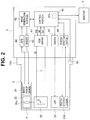
- FIG. 2 is a block diagram showing a configuration of the endoscope apparatus 1 according to the first embodiment of the present invention
- FIG. 3 is a block diagram showing a configuration of a VCM driver 41 according to the first embodiment of the present invention
- FIG. 4 is a wiring diagram to explain a resistance value of two signal wires L and a resistance value of a voice coil motor 32 to be viewed from output ends OUT of the VCM driver 41 according to the first embodiment of the present invention
- FIG. 5 provides schematic graphs showing temperature changes in a distal end portion 21 corresponding to power consumption in an internal resistance R 2 of the voice coil motor 32 and with the lapse of time, according to the first embodiment of the present invention
- FIG. 6 is a flowchart showing an example of a flow of temperature maintenance processes in the distal end portion 21 of the endoscope apparatus 1 according to the first embodiment of the present invention
- FIG. 7 is a flowchart showing an example of a flow of temperature maintenance processes in the distal end portion 21 of the endoscope apparatus 1 according to a second embodiment of the present invention.
- FIG. 8 provides a graph showing a change in an integrated value of power consumption according to the second embodiment of the present invention.
- FIG. 9 is a flowchart showing an example of a flow of temperature maintenance processes in the distal end portion 21 of the endoscope apparatus 1 according to a modification 3.
- FIG. 1 is a configuration diagram showing a configuration of an endoscope apparatus according to the present embodiment.
- an endoscope apparatus 1 according to the present embodiment is configured to have an endoscope 2 and a video processor 3 to which the endoscope 2 is connected.
- a monitor 4 is connected to the video processor 3 .
- the video processor 3 serving as an image processing apparatus has a connector and the endoscope 2 is a main body portion that is connectable to the connector.
- a user who conducts an endoscopic examination can select any endoscope 2 from a plurality of endoscopes according to the examination and connect the selected endoscope 2 to the video processor 3 .
- the endoscope 2 is an electronic endoscope that has an elongated insertion portion 11 , an operation portion 12 connected to a proximal end of the insertion portion 11 , and a universal cable 13 extending from the operation portion 12 .
- the insertion portion 11 of the endoscope 2 has a rigid distal end portion 21 at a tip end and a bendable bending portion 22 provided adjacent to the distal end portion 21 , and further includes a long flexible tube portion 23 disposed to a proximal end side of the bending portion 22 .
- the distal end portion 21 incorporates an image pickup device 34 and an image pickup optical system 35 (see FIG. 2 ).
- the distal end portion 21 is provided with an observation window (not shown) and light from an object passes through the observation window and the image pickup optical system 35 to be made incident on a light receiving surface of the image pickup device 34 .
- the image pickup optical system 35 is an observation optical system having a zoom mechanism. An image pickup signal obtained by the image pickup device 34 is supplied to the video processor 3 via signal wires inserted into the insertion portion 11 , the operation portion 12 and the universal cable 13 .
- the image pickup optical system 35 serving herein as an observation optical system having a zoom mechanism with variable image pickup magnifications may also be an observation optical system having a mechanism to drive a lens instead of the zoom mechanism.
- the image pickup optical system 35 should have at least a lens driving mechanism.
- the distal end portion 21 is further provided with an illumination window (not shown).
- a light emitting diode 33 (see FIG. 2 ) is disposed to a rear side of the illumination window to emit illumination light.
- a user of the endoscope apparatus 1 is allowed to bend the bending portion 22 in vertical and horizontal directions by operating two bending knobs 24 provided in the operation portion 12 .
- the operation portion 12 is provided with various operating tools such as a release button, and a zoom operating tool 25 for driving a zoom lens to be described later.
- the zoom operating tool 25 has a button 25 a configured to cause zooming to a tele side of the zoom mechanism, and a button 25 b configured to cause zooming to a wide side of the zoom mechanism.
- a zoom lens 35 a (see FIG. 2 ) is moved for zooming to the tele side.
- the zoom lens 35 a stops in a zoom position at that time.
- the zoom lens 35 a is moved for zooming to the wide side.
- the zoom lens 35 a stops in a zoom position at that time. Therefore, a user is allowed to observe an object in a desired zoom position or zoom amount by the operation of pressing the buttons 25 a , 25 b.
- zoom operating tool 25 provided herein as the two buttons 25 a , 25 b arranged in the operation portion 12 of the endoscope 2 may also be any of other operating tools such as a foot switch connected to the video processor 3 .
- a connector 13 a is provided at a tip end of the universal cable 13 extending from the operation portion 12 (i.e., at a proximal end of the endoscope 2 ).
- the connector 13 a can be detachably attached to a connector of the video processor 3 .
- the video processor 3 incorporates a control portion 40 (see FIG. 2 ) configured to control the endoscope apparatus 1 as a whole.
- a user can perform various operations by using various buttons of the operation portion 12 and an operation panel 3 a , etc. of the video processor 3 .
- the control portion 40 executes programs according to various functions in response to operation by a user.
- the video processor 3 is a processor configured to receive an image pickup signal from the endoscope 2 and generate an endoscope image as an object image. An image signal of the endoscope image is outputted to the monitor 4 to display the endoscope image on the monitor 4 .
- the endoscope 2 has a zoom function and a user operates the zoom operating tool 25 so as to display an endoscope image on the monitor 4 at an angle of view as desired by the user.
- the video processor 3 drives an actuator of the endoscope 2 in response to operation of the zoom operating tool 25 by a user.
- the endoscope apparatus 1 is composed of an endoscope 2 having an observation optical system that has a lens driving mechanism, and the video processor 3 serving as a processor to which the endoscope 2 is connected.
- FIG. 2 is a block diagram showing a configuration of the endoscope apparatus 1 .
- the endoscope 2 includes an image pickup portion 31 , a voice coil motor 32 serving as an actuator, the light emitting diode (hereinafter referred to as LED) 33 , and a position detection sensor 33 A.
- the image pickup portion 31 , the voice coil motor (VCM) 32 , the LED 33 and the position detection sensor 33 A are provided inside the distal end portion 21 of the insertion portion 11 .
- the image pickup portion 31 has the image pickup device 34 such as a CCD image sensor and the image pickup optical system 35 .
- the image pickup optical system 35 is a zoom optical system as stated above and includes the zoom lens 35 a that is a movable lens.
- the image pickup device 34 receives, on the light receiving surface, light from an object image via the image pickup optical system 35 and photoelectrically converts the received light to output as an image pickup signal.
- the voice coil motor 32 is an electric actuator provided in the endoscope 2 and configured to drive a lens associated with a lens driving mechanism of the zoom optical system.
- the voice coil motor 32 can move the zoom lens 35 a in an optical axis direction of the image pickup optical system 35 .
- the voice coil motor 32 is a magnetic actuator composed of a coil C and a magnet and driven by a drive current DI. When the drive current DI is supplied to the voice coil motor 32 and the voice coil motor 32 is driven, the coil C generates heat.
- the zoom lens 35 a is connected to a movable portion of the voice coil motor 32 and the movable portion is moved relative to a fixed portion inside the voice coil motor 32 , whereby the zoom lens 35 a can be moved by the voice coil motor 32 in the optical axis direction of the image pickup optical system 35 .
- the actuator provided in the distal end portion 21 is a voice coil motor that has at least one magnet and at least one coil C and is capable of moving the movable portion relative to the fixed portion.
- the position detection sensor 33 A detects a position of the zoom lens 35 a or the movable portion of the voice coil motor in the optical axis direction.
- the position detection sensor 33 A is, for example, a hall device.
- the LED 33 is a light emitting device configured to emit light serving as illumination light, and emits illumination light from the illumination window (not shown) of the distal end portion 21 to an object.
- a light source apparatus may be provided separately to expose illumination light onto an object by guiding light from the light source apparatus to the distal end portion 21 with the use of a light guide composed of an optical fiber bundle and emitting light from a tip end surface of the light guide in the distal end portion 21 .
- the endoscope 2 includes a memory 36 .
- the memory 36 is provided herein inside the connector 13 a of the universal cable 13 .
- the memory 36 is a rewritable nonvolatile memory or, for example, a flash memory.
- Predetermined information is stored in the memory 36 in advance.
- the predetermined information includes resistance value ratio information Rat and power consumption threshold information pTH. Details of the information are described later.
- predetermined information may also be stored in a storage apparatus such as a ROM in the video processor 3 .
- model information of the endoscope 2 is stored in the memory 36 of the endoscope 2 and a plurality of predetermined information corresponding to models are stored in a ROM or the like of the video processor 3 .
- the video processor 3 can read, from a ROM or the like, predetermined information corresponding to a model of the endoscope 2 that is connected to the video processor 3 .
- the video processor 3 serving as a main body portion of the endoscope apparatus 1 includes the control portion 40 , a voice coil motor driver (hereinafter referred to as the VCM driver) 41 , an image generation portion 42 , a driver 43 , an analog front end circuit (hereinafter referred to as AFE) 44 , a driver 45 , and a position detection portion 46 .
- VCM driver voice coil motor driver
- AFE analog front end circuit
- the control portion 40 makes a control to drive the voice coil motor 32 in addition to perform various processes corresponding to the entire operation of the endoscope apparatus 1 , generation of various images and various functions.
- the control portion 40 includes a central processing unit (CPU), a ROM, a RAM and the like not shown and temperature maintenance processes to be described later are performed by executing a program stored in the ROM. Note that FIG. 2 shows only a plurality of blocks relevant to the control to drive the voice coil motor 32 .
- the VCM driver 41 generates, based on a drive instruction signal DS sent from the control portion 40 , the drive current DI supplied to the voice coil motor 32 , and outputs the drive current DI to the voice coil motor 32 via two signal wires L. Further, the VCM driver 41 outputs, to the control portion 40 , a current value signal SI corresponding to a current supplied to the voice coil motor 32 , and a voltage value signal SV corresponding to a voltage at an output end of the VCM driver 41 .
- a zoom instruction signal is outputted from the zoom operating tool 25 to the control portion 40 .
- the control portion 40 outputs, based on the zoom instruction signal, the drive instruction signal DS to drive the voice coil motor 32 , whereby the zoom lens 35 a is moved. Owing to the movement of the zoom lens 35 a , a zoom position of the image pickup optical system 35 changes and, as a result, a size of an object image displayed on the monitor 4 is changed.
- VCM driver 41 provided herein in the video processor 3 may also be provided in the endoscope 2 .
- the VCM driver 41 may also be provided inside the connector 13 a of the endoscope 2 .
- FIG. 3 is a block diagram showing a configuration of the VCM driver 41 .
- the VCM driver 41 includes a drive circuit 51 , a current sensor 52 and a voltage sensor 53 .
- the drive circuit 51 receives the drive instruction signal DS from the control portion 40 and outputs the drive current DI that is a drive signal corresponding to the drive instruction signal DS.
- the current sensor 52 detects the magnitude of a current of the drive signal DI flowing through the signal wires L by which the VCM driver 41 and the voice coil motor 32 are connected, and outputs the current value signal SI indicating a current value to the control portion 40 .
- the voltage sensor 53 detects the magnitude of a voltage between the two output ends OUT connected to the signal wires L by which the VCM driver 41 and the voice coil motor 32 are connected, and outputs the voltage value signal SV indicating a voltage value to the control portion 40 .
- FIG. 4 is a wiring diagram to explain a resistance value of the two signal wires L and a resistance value of the voice coil motor 32 to be viewed from the output ends OUT of the VCM driver 41 .
- the two signal wires L viewed from the output ends OUT of the VCM driver 41 include two resistance components.
- Each of the signal wires L has a length of, for example, 4 m and a conductor resistance R 1 corresponding to the length.
- the conductor resistance R 1 has a resistance value r 1 .
- the voice coil motor 32 has an internal resistance R 2 and the internal resistance R 2 has a resistance value r 2 .
- a resistance value of the coil C of the voice coil motor 32 corresponds to the resistance value r 2 of the internal resistance R 2 .
- the coil C of the voice coil motor 32 serving as an actuator is a device provided in the distal end portion 21 of the insertion portion 11 and having a resistance component of the resistance value r 2 .
- the two signal wires L are inserted into the insertion portion 11 and connected to both ends of the coil C as the device.
- the sum of the resistance values r 1 , r 2 corresponds to a composite resistance value R included in the signal wires L viewed from the output ends OUT.
- a current value of the drive signal DI outputted from the output end OUT of the VCM driver 41 and a voltage between the output ends OUT vary according to the resistance values r 1 , r 2 .
- the resistance value r 1 is 8 ohms and the resistance value r 2 is 24 ohms.
- the current sensor 52 and the voltage sensor 53 constitute a signal detection portion to detect a current supplied to the two signal wires L and a voltage applied to the two signal wires L, respectively.
- the endoscope 2 of various kinds may be connected to the video processor 3 , in which the resistance values r 1 , r 2 vary depending on each model of the endoscope 2 . Further, the resistance values r 1 , r 2 may be set to a constant design value but vary owing to individual differences.
- the image generation portion 42 includes a circuit configured to output, under the control of the control portion 40 , a drive signal to drive the driver 43 for the image pickup portion 31 and to receive an image signal from the AFE 44 to generate an endoscope image.
- the image generation portion 42 generates an endoscope image by applying various processes to the image signal from the AFE 44 and outputs the endoscope image to the control portion 40 .
- the control portion 40 outputs an image signal of the endoscope image to the monitor 4 .
- the driver 43 generates various drive signals including a horizontal synchronizing signal and a vertical synchronizing signal to drive the image pickup device 34 and outputs the various drive signals to the image pickup device 34 .
- the AFE 44 includes an analog-digital converter or the like to convert an image pickup signal from the image pickup portion 31 into a digital signal and outputs an image pickup signal subjected to a noise removal process or other processes to the image generation portion 42 .
- the driver 45 generates, under the control of the control portion 40 , a drive signal to drive the LED 33 and outputs the drive signal to the LED 33 .
- the video processor 3 drives the LED 33 to irradiate an object with illumination light and generates, based on an image pickup signal from the image pickup portion 31 that receives light reflected from the object, an image signal to output to the monitor 4 and causes an endoscope image to be displayed on a display screen of the monitor 4 .
- the position detection portion 46 generates, under the control of the control portion 40 , a drive signal to drive the position detection sensor 36 and outputs the drive signal to the position detection sensor 36 .
- the position detection portion 46 outputs, based on a position detection signal received from the position detection sensor 36 , a position detection value to the control portion 40 .
- the distal end portion 21 When the drive current DI is supplied to the voice coil motor 32 , the distal end portion 21 generates heat due to power consumption in the resistance value r 2 of the voice coil motor 32 .
- FIG. 5 shows schematic graphs indicating temperature changes in the distal end portion 21 corresponding to power consumption in the internal resistance R 2 of the voice coil motor 32 and with the lapse of time.
- the graphs shown in FIG. 5 are plotted from data obtained through, for example, experiment or simulation.
- the graphs of FIG. 5 are created in such a manner that the drive current DI is changed for each model of the endoscope 2 and temperature of the distal end portion 21 corresponding to power consumption of the internal resistance R 2 are obtained through measurement or simulation so as to be plotted.
- the distal end portion 21 incorporates the image pickup device 34 , the voice coil motor 32 and the LED 33 .
- a temperature of distal end portion 21 is estimated based on power consumption of the voice coil motor 32 .
- a heat capacity and heat dissipation characteristics of the distal end portion 21 are determined by a structure and a material, etc. of the distal end portion 21 and a use environment of the endoscope. Due to a design value and an allowable error of each component to constitute the endoscope 2 and production variations of the endoscope 2 , a power consumption threshold varies depending on each endoscope.
- model information of the endoscope may be stored in the memory 36 of the endoscope 2 and information of power consumption thresholds for respective models of the endoscope may be stored in a nonvolatile memory 40 a (shown by broken line in FIG. 2 ) of the control portion 40 .
- the control portion 40 may read model information of the endoscope 2 from the memory 36 and read a power consumption threshold by referring to the memory 40 a based on the model information.
- a graph g 1 shown by a one-dot dashed line indicates a temperature change in the distal end portion 21 when the drive current DI having a first current value is made to flow through the signal wires L and power consumption of the internal resistance R 2 of the voice coil motor 32 is p 1 .
- the graph g 1 shows upward movement with the lapse of time and no change from certain time so that the distal end portion 21 is stabilized at a temperature T 1 .
- a graph g 2 shown by a solid line indicates a temperature change in the distal end portion 21 when the drive current DI having a second current value that is greater than the first current value is made to flow through the signal wires L and power consumption of the internal resistance R 2 is p 2 .
- the graph g 2 also shows upward movement with the lapse of time and no change from certain time so that the distal end portion 21 is stabilized at a temperature T 2 .
- a graph g 3 shown by a two-dot dashed line indicates a temperature change in the distal end portion 21 when the drive current DI having a third current value that is greater than the second current value is made to flow through the signal wires L and power consumption of the internal resistance R 2 is p 3 .
- the graph g 3 also shows upward movement with the lapse of time and no change from certain time so that the distal end portion 21 is stabilized at a temperature T 3 .
- FIG. 5 shows only three graphs, a plurality of graphs may be obtained through experiment or simulation by causing a plurality of the drive currents DI having mutually different current values to flow through the signal wires L.
- a temperature of the distal end portion 21 rises too high, it causes, for example, an increased noise amount included in an image pickup signal of the image pickup device 34 and therefore prevents achieving a predetermined image quality level.
- a temperature of the distal end portion 21 rises too high, it prevents maintaining a predetermined performance level of the endoscope 2 .
- the temperature of the distal end portion 21 can be maintained below TH when power consumption of the internal resistance R 2 is P 2 or less. Therefore, the p 2 is stored as a power consumption threshold pTH in the memory 36 in advance.
- Information of a ratio between the resistance value r 1 of the signal wires L and the resistance value r 2 of the voice coil motor 32 is also stored in the memory 36 in advance.
- the ratio information is stored in the memory 36 because even if there is a change in a use environment of the endoscope apparatus 1 , a ratio (r 2 /r 1 ) of the resistance value r 2 of the voice coil motor 32 to the resistance value r 1 of the signal wires L is substantially constant.
- information of the resistance values r 1 , r 2 may be stored as predetermined information in the memory 36 in place of the ratio information so as to calculate a ratio from the resistance values r 1 , r 2 by the control portion 40 .
- the resistance value r 1 of the signal wires L and the resistance value r 2 of the voice coil motor 32 are actually measured in the same environment as the use environment as stated above.
- the ratio (r 2 /r 1 ) of the resistance value r 2 of the voice coil motor 32 to the resistance value r 1 of the signal wires L is actually measured when the distal end portion 21 is at, for example 40 degrees and portions other than the distal end portion 21 are at a room temperature that is, for example, 25 degrees, and the ratio information Rat is stored in the memory 36 .
- the ratio information Rat is resistance value information of a resistance component of the coil C.
- the ratio information Rat obtained by actually measuring the ratio (r 2 /r 1 ) of the resistance value r 2 to the resistance value r 1 when the distal end portion 21 and portions other than the distal end portion 21 are at the same temperature may be stored in the memory 36 .
- a design value may also be used without actual measurement of the resistance values r 1 , r 2 .
- a design value set at, for example, 25 degrees may be used as r 1 and a design value set at, for example, 40 degrees may be used as r 2 .
- FIG. 6 is a flowchart showing an example of a flow of temperature maintenance processes applied to the distal end portion 21 in the endoscope apparatus 1 .
- a process program in FIG. 6 is stored in the ROM and read by the CPU in the control portion 40 .
- the control portion 40 first calculates the resistance value r 2 of the internal resistance R 2 as a point resistance in the voice coil motor 32 (step (hereinafter referred to as S) 1 ).
- the control portion 40 can calculate power consumption of the internal resistance R 2 of the voice coil motor 32 from the current value signal SI and the voltage value signal SV sent from the VCM driver 41 and the ratio information Rat stored in the memory 36 .
- the composite resistance value R is expressed by an equation (2) below.
- R r 1+ r 2 (2)
- the internal resistance R 2 as a point resistance is a coil resistance that constitutes the voice coil motor 32 .
- the resistance value r 2 is calculated.
- the process at S 2 constitutes a power consumption calculation part to calculate power consumption of the coil C by using the current value I and the voltage value V detected by the current sensor 52 and the voltage sensor 53 serving as a signal detection portion and the ratio information Rat serving as resistance value information of the resistance component of the coil C.
- resistance value information of the resistance component of the coil C is obtained from the ROM based on the model information read from the memory 36 and power consumption is calculated by using the obtained resistance value information at S 2 .
- control portion 40 determines whether or not power consumption calculated at S 2 exceeds the threshold pTH read from the memory 36 (S 3 ).
- control portion 40 executes a predetermined process (S 4 ).
- a temperature of the distal end portion 21 is presumed to exceed the threshold TH with the lapse of time as shown by the graph g 3 in FIG. 4 to prevent the endoscope apparatus 1 from maintaining a predetermined performance level.
- a process to prevent a temperature rise in the distal end portion 21 or, for example, a process to stop power supply to the signal wires L and stop operation of the voice coil motor 32 serving as an actuator for a predetermined period is performed.
- the control portion 40 thus makes a control to execute a predetermined process based on power consumption of the internal resistance R 2 as calculated at S 2 serving as a power consumption calculation part and the threshold pTH serving as power consumption threshold information.
- the control portion 40 executes a predetermined process and then, after the lapse of a predetermined period, executes the processes shown in FIG. 6 again. It is thus possible to maintain or manage a temperature of the distal end portion 21 without exceeding the threshold TH.
- the predetermined process executed at S 4 in the aforementioned example when power consumption of the internal resistance R 2 exceeds the threshold pTH may also be executed in a stepwise manner once or several times before power consumption of the internal resistance R 2 reaches the threshold pTH by setting a plurality of thresholds in advance.
- the control portion 40 may execute a predetermined process such as alternation to a drive mode with a smaller amount of heat generation to make a control to drive the image pickup device 34 .
- control in the aforementioned example is set to prevent a temperature of the distal end portion 21 from reaching the threshold TH or above based on power consumption of the voice coil motor 32 on the assumption that a temperature of the distal end portion 21 is most affected by power consumption of the voice coil motor 32 .
- a relationship between power consumption of each of other components inside the distal end portion 21 such as the image pickup portion 31 , the LED 33 and the position detection sensor 33 A and a temperature change in the distal end portion 21 may be obtained in advance through experiment or the like to maintain and manage a temperature of the distal end portion 21 by adjusting a temperature of each of other components with the use of information of the relationship between power consumption of each of other components and a temperature change in the distal end portion 21 .
- the first embodiment involves comparison between power consumption of the internal resistance R 2 and the power consumption threshold pTH, whereas a second embodiment involves comparison between an integrated value of power consumption for a predetermined period and a power consumption integrated value threshold SpTH.
- Components of an endoscope apparatus according to the second embodiment are substantially the same as the components of the endoscope apparatus 1 according to the first embodiment and therefore explanation is made only for different components while omitting explanation of the same constituent elements to which the same reference numbers are given.
- the aforementioned ratio information Rat and information of the integrated value threshold SpTH to be described later are stored in the memory 36 in advance.
- FIG. 7 is a flowchart showing an example of a flow of temperature maintenance processes applied to the distal end portion 21 in the endoscope apparatus 1 .
- a process program in FIG. 7 is stored in the ROM and read by the CPU in the control portion 40 .
- the processes in FIG. 7 contain the same processes shown in FIG. 6 and therefore the same processes as the processes in FIG. 6 are provided with the same step numbers to simplify explanation.
- the control portion 40 calculates the resistance value r 2 of the internal resistance R 2 of the voice coil motor 32 (S 1 ), and calculates power consumption of the resistance value r 2 of the internal resistance R 2 of the voice coil motor 32 (S 2 ). Power consumption of the resistance value r 2 is calculated by using the aforementioned equations (1) to (6). A power consumption value calculated at S 2 is temporarily stored for a predetermined period TT in the RAM of the control portion 40 .
- the control portion 40 calculates an integrated value of power consumption calculated during the predetermined period TT from a current point of time (S 11 ).
- the predetermined period TT falls in a range of, for example, several minutes to several tens of minutes.
- the control portion 40 determines whether or not an integrated value of power consumption calculated at S 11 exceeds the integrated value threshold SpTH read from the memory 36 (S 12 ). Namely, an integrated value of power consumption for the predetermined period TT is calculated at S 2 and S 11 .
- Power consumption threshold information SpTH is a value corresponding to the predetermined period TT.
- control portion 40 executes a predetermined process (S 4 ).
- FIG. 8 provides a graph showing a change in an integrated value of power consumption PS.
- a graph g 4 indicates a change in an integrated value of power consumption PS of the internal resistance R 2 .
- An integrated value of power consumption PS varies as shown in FIG. 8 .
- the integrated value threshold SpTH is a threshold of an integrated value of power consumption PS of the internal resistance R 2 .
- a temperature of the distal end portion 21 is presumed to exceed the threshold TH.
- the integrated value threshold SpTH is determined through experiment or simulation and stored in the memory 36 .
- the integrated value threshold SpTH is a value corresponding to an upper limit value of a temperature of the distal end portion 21 in which the endoscope apparatus 1 can maintain a predetermined performance level.
- a temperature of the distal end portion 21 is presumed to exceed the threshold TH when a certain period of time elapses in the state where power consumption of the internal resistance R 2 exceeds the threshold pTH.
- a temperature of the distal end portion 21 does not immediately reach the threshold TH.
- power consumption of the internal resistance R 2 increases temporarily and then decreases, a temperature of the distal end portion 21 does not reach the threshold TH or more.
- a temperature of the distal end portion 21 is presumed to reach the threshold TH or more when an integrated value of power consumption for the predetermined period TT exceeds the integrated value threshold SpTH.
- an integrated value of power consumption PS exceeds the integrated value threshold SpTH at time t 1 and the control portion 40 then executes a predetermined process such as a process to stop operation of the voice coil motor 32 for a predetermined period.
- the control portion 40 executes the predetermined process and then, after the lapse of a predetermined period, executes the processes in FIG. 7 again.
- a temperature of the distal end portion 21 can be maintained or managed while reflecting effects of a heat capacity of the distal end portion 21 .
- the current value I of a current flowing through the two signal wires L and the voltage value V between the two signal wires L are detected to calculate power consumption of the internal resistance R 2 with the use of the ratio information Rat stored in the memory 36 .
- the current value I of a current flowing through the two signal wires L is detected to calculate power consumption of the internal resistance R 2 with the use of the resistance value r 2 of the internal resistance R 2 stored in the memory 36 and the current value I.
- information of the composite resistance value R and the resistance value r 1 of the signal wires L may be stored in the memory 36 so as to calculate the resistance value r 2 in the control portion 40 from the composite resistance value R and the resistance value r 1 .
- the first embodiment involves calculation of the resistance value r 2 of the internal resistance R 2 while considering temperature characteristics of the internal resistance R 2 in a use environment of the endoscope apparatus 1 .
- the present modification 1 is applicable in the case where the resistance value r 2 of the internal resistance R 2 can be presumed to be constant in view of temperature characteristics.
- the current value I of a current flowing through the two signal wires L and the voltage value V between the two signal wires L are detected to calculate power consumption of the internal resistance R 2 with the use of the ratio information Rat stored in the memory 36 .
- the voltage value V between the two signal wires L is detected to calculate power consumption of the resistance value r 2 of the internal resistance R 2 with the use of the composite resistance value R stored in the memory 36 , the resistance value r 2 of the internal resistance R 2 and the voltage value V.
- the voltage value V detected by the voltage sensor 53 serving as a signal detection portion and the composite resistance value R stored in the memory 36 are used to calculate the current value I of a current flowing through the two signal wires L, and the calculated current value I and the resistance value r 2 stored in the memory 36 are used to calculate power consumption of the internal resistance R 2 .
- information of the composite resistance value R and the resistance value r 1 of the signal wires L may be stored in the memory 36 to calculate the resistance value r 2 from the composite resistance value R and the resistance value r 1 .
- the resistance value r 2 of the internal resistance R 2 is calculated while considering temperature characteristics of the internal resistance R 2 in a use environment of the endoscope apparatus 1 .
- the present modification 2 is applicable in the case where the resistance value r 1 of the conductor resistance R 1 and the resistance value r 2 of the internal resistance R 2 can be both presumed to be constant in view of temperature characteristics.
- an allowable value is set in advance for the composite resistance value R and it is determined whether the composite resistance value R exceeds the allowable value or not.
- the allowable value is a value set in advance to allow correct calculation of power consumption. If the composite resistance value R exceeds the allowable value, the control portion 40 executes a predetermined process.
- FIG. 9 is a flowchart showing an example of a flow of temperature maintenance processes applied to the distal end portion 21 in the endoscope apparatus 1 according to the present modification 3.
- the same processes as the processes in FIG. 6 are provided with the same step numbers to simplify explanation.
- the control portion 40 calculates the composite resistance value R from the current value I and the voltage value V (S 20 ). The control portion 40 then determines whether or not the composite resistance value R is the predetermined threshold THa or more (S 21 ).
- the threshold THa is the aforementioned allowable value.
- the control portion 40 stops function of the voice coil motor 32 (S 22 ). Namely, the voice coil motor 32 is brought into an unoperated state. After S 22 , no process is performed.
- the process at S 20 constitute a composite resistance detection part to detect the composite resistance value R of the resistance value r 2 of the resistance component of the coil C and the resistance value r 1 of the two signal wires L, and the control portion 40 does not execute a predetermined process when the composite resistance value R detected by the composite resistance detection part is a predetermined threshold THa or more.
- the control portion 40 executes the process at S 1 .
- the processes after S 1 are as stated above.
- the present modification 3 it is prevented to calculate inaccurate power consumption resulting from an increased resistance value of the signal wires L or the like due to a change with time of the signal wires L.
- abnormality of the internal resistance R 2 and the signal wires L can be detected and therefore a temperature of the distal end portion 21 can be maintained or managed more appropriately.
- a composite resistance value of each of other components may also be detected in the same manner as the case of the coil C to detect abnormality of an internal resistance and a signal wire of each of other components such as the image pickup portion 31 .
- the control portion 40 executes a predetermined process. Then, a composite resistance value of a resistance value of the resistance component of the position detection sensor 33 A and a resistance value of the signal wires of the two sensors is detected.
- the control portion 40 makes a control to execute a predetermined process such as a process to stop operation of the position detection sensor 33 A.
- the present invention is not limited to the aforementioned embodiments and various changes and modifications, etc. can be made in the range without changing the gist of the present invention.
Landscapes
- Health & Medical Sciences (AREA)
- Life Sciences & Earth Sciences (AREA)
- Engineering & Computer Science (AREA)
- Surgery (AREA)
- Physics & Mathematics (AREA)
- Medical Informatics (AREA)
- General Health & Medical Sciences (AREA)
- Nuclear Medicine, Radiotherapy & Molecular Imaging (AREA)
- Radiology & Medical Imaging (AREA)
- Optics & Photonics (AREA)
- Animal Behavior & Ethology (AREA)
- Heart & Thoracic Surgery (AREA)
- Biomedical Technology (AREA)
- Molecular Biology (AREA)
- Pathology (AREA)
- Biophysics (AREA)
- Public Health (AREA)
- Veterinary Medicine (AREA)
- General Physics & Mathematics (AREA)
- Quality & Reliability (AREA)
- Computer Vision & Pattern Recognition (AREA)
- Theoretical Computer Science (AREA)
- Signal Processing (AREA)
- Astronomy & Astrophysics (AREA)
- Artificial Intelligence (AREA)
- Evolutionary Computation (AREA)
- Instruments For Viewing The Inside Of Hollow Bodies (AREA)
- Endoscopes (AREA)
Abstract
Description
R=V/I (1)
R=r1+r2 (2)
r1=r2/Rat (3)
r2=R−r1=R−(r2/(Rat)) (4)
r2=(R×Rat)/(Rat+1) (5)
PWr2=I 2 ×r2 (6)
Claims (20)
Applications Claiming Priority (1)
| Application Number | Priority Date | Filing Date | Title |
|---|---|---|---|
| PCT/JP2017/015587 WO2018193519A1 (en) | 2017-04-18 | 2017-04-18 | Endoscope device and video processor |
Related Parent Applications (1)
| Application Number | Title | Priority Date | Filing Date |
|---|---|---|---|
| PCT/JP2017/015587 Continuation WO2018193519A1 (en) | 2017-04-18 | 2017-04-18 | Endoscope device and video processor |
Publications (2)
| Publication Number | Publication Date |
|---|---|
| US20200037849A1 US20200037849A1 (en) | 2020-02-06 |
| US11213186B2 true US11213186B2 (en) | 2022-01-04 |
Family
ID=63856627
Family Applications (1)
| Application Number | Title | Priority Date | Filing Date |
|---|---|---|---|
| US16/654,090 Expired - Fee Related US11213186B2 (en) | 2017-04-18 | 2019-10-16 | Endoscope apparatus and image processing apparatus |
Country Status (2)
| Country | Link |
|---|---|
| US (1) | US11213186B2 (en) |
| WO (1) | WO2018193519A1 (en) |
Cited By (1)
| Publication number | Priority date | Publication date | Assignee | Title |
|---|---|---|---|---|
| US12566142B2 (en) * | 2022-11-15 | 2026-03-03 | Lasertec Corporation | Optical apparatus and examination apparatus |
Families Citing this family (1)
| Publication number | Priority date | Publication date | Assignee | Title |
|---|---|---|---|---|
| CN112991333B (en) * | 2021-04-21 | 2021-08-10 | 强基(上海)医疗器械有限公司 | Image processing method and system based on voice analysis in endoscopic surgery |
Citations (21)
| Publication number | Priority date | Publication date | Assignee | Title |
|---|---|---|---|---|
| JP2003333873A (en) | 2002-05-17 | 2003-11-21 | Fuji Electric Co Ltd | Resistor overheat protection method |
| US20040090189A1 (en) * | 2002-10-16 | 2004-05-13 | Kenji Yoneda | Electric power supply system for LED lighting unit |
| US20070038030A1 (en) * | 2005-08-10 | 2007-02-15 | Pentax Corporation | Endoscope |
| JP2007229262A (en) | 2006-03-01 | 2007-09-13 | Fujinon Corp | Endoscopic apparatus |
| US20070244366A1 (en) * | 2005-11-08 | 2007-10-18 | Olympus Corporation | Electronic endoscope |
| US20080027284A1 (en) * | 2006-07-28 | 2008-01-31 | Pentax Corporation | Endoscope Having Power Shutdown Unit |
| US20080076087A1 (en) * | 2006-09-26 | 2008-03-27 | Olympus Corporation | Optical component anti-fogging system, oral cavity internal observation device, and anti-fogging method |
| US20090203965A1 (en) * | 2008-02-12 | 2009-08-13 | Olympus Corporation | Endoscope apparatus and method of controlling endoscope apparatus |
| US20090284588A1 (en) * | 2007-02-05 | 2009-11-19 | Olympus Corporation | Endoscope apparatus |
| US20120004509A1 (en) * | 2010-06-30 | 2012-01-05 | Welch Allyn, Inc. | Drive Circuit for Light Emitting Diode |
| JP2012065850A (en) | 2010-09-24 | 2012-04-05 | Olympus Corp | Endoscope cooling device |
| US20120178992A1 (en) * | 2010-07-12 | 2012-07-12 | Olympus Medical Systems Corp. | Endoscopic image processing apparatus and endoscope system |
| US20130030248A1 (en) * | 2011-07-26 | 2013-01-31 | Matsumaru Yasushi | Electronic endoscope apparatus and electronic endoscope system |
| US20130197308A1 (en) * | 2010-09-30 | 2013-08-01 | Olympus Corporation | Endoscopic apparatus and operation control method for the same |
| US20130265403A1 (en) * | 2011-09-22 | 2013-10-10 | Olympus Medical Systems Corp. | Endoscope |
| US20140275783A1 (en) * | 2013-03-15 | 2014-09-18 | Olive Medical Corporation | Minimize image sensor i/o and conductor counts in endoscope applications |
| JP2015125094A (en) | 2013-12-27 | 2015-07-06 | 日野自動車株式会社 | Intake heater temperature estimation device and engine start assist system |
| JP2015141278A (en) | 2014-01-28 | 2015-08-03 | オリンパス株式会社 | Drive unit, optical unit, imaging device, and endoscope |
| US20150280550A1 (en) * | 2014-03-31 | 2015-10-01 | Hoya Corporation | Load voltage control device, electronic endoscope and electronic endoscope system |
| US20160037079A1 (en) * | 2013-07-29 | 2016-02-04 | Olympus Corporation | Image pickup apparatus |
| US20160353540A1 (en) * | 2015-05-26 | 2016-12-01 | Heine Optotechnik Gmbh & Co Kg | Technique for adjusting the brightness of led lamps |
-
2017
- 2017-04-18 WO PCT/JP2017/015587 patent/WO2018193519A1/en not_active Ceased
-
2019
- 2019-10-16 US US16/654,090 patent/US11213186B2/en not_active Expired - Fee Related
Patent Citations (24)
| Publication number | Priority date | Publication date | Assignee | Title |
|---|---|---|---|---|
| JP2003333873A (en) | 2002-05-17 | 2003-11-21 | Fuji Electric Co Ltd | Resistor overheat protection method |
| US20040090189A1 (en) * | 2002-10-16 | 2004-05-13 | Kenji Yoneda | Electric power supply system for LED lighting unit |
| US20070038030A1 (en) * | 2005-08-10 | 2007-02-15 | Pentax Corporation | Endoscope |
| US20070244366A1 (en) * | 2005-11-08 | 2007-10-18 | Olympus Corporation | Electronic endoscope |
| JP2007229262A (en) | 2006-03-01 | 2007-09-13 | Fujinon Corp | Endoscopic apparatus |
| US20080027284A1 (en) * | 2006-07-28 | 2008-01-31 | Pentax Corporation | Endoscope Having Power Shutdown Unit |
| US20080076087A1 (en) * | 2006-09-26 | 2008-03-27 | Olympus Corporation | Optical component anti-fogging system, oral cavity internal observation device, and anti-fogging method |
| US20090284588A1 (en) * | 2007-02-05 | 2009-11-19 | Olympus Corporation | Endoscope apparatus |
| US20090203965A1 (en) * | 2008-02-12 | 2009-08-13 | Olympus Corporation | Endoscope apparatus and method of controlling endoscope apparatus |
| US20120004509A1 (en) * | 2010-06-30 | 2012-01-05 | Welch Allyn, Inc. | Drive Circuit for Light Emitting Diode |
| US20120178992A1 (en) * | 2010-07-12 | 2012-07-12 | Olympus Medical Systems Corp. | Endoscopic image processing apparatus and endoscope system |
| JP2012065850A (en) | 2010-09-24 | 2012-04-05 | Olympus Corp | Endoscope cooling device |
| US20130197308A1 (en) * | 2010-09-30 | 2013-08-01 | Olympus Corporation | Endoscopic apparatus and operation control method for the same |
| US20130030248A1 (en) * | 2011-07-26 | 2013-01-31 | Matsumaru Yasushi | Electronic endoscope apparatus and electronic endoscope system |
| US20130265403A1 (en) * | 2011-09-22 | 2013-10-10 | Olympus Medical Systems Corp. | Endoscope |
| US20140275783A1 (en) * | 2013-03-15 | 2014-09-18 | Olive Medical Corporation | Minimize image sensor i/o and conductor counts in endoscope applications |
| US20160037079A1 (en) * | 2013-07-29 | 2016-02-04 | Olympus Corporation | Image pickup apparatus |
| JP2015125094A (en) | 2013-12-27 | 2015-07-06 | 日野自動車株式会社 | Intake heater temperature estimation device and engine start assist system |
| JP2015141278A (en) | 2014-01-28 | 2015-08-03 | オリンパス株式会社 | Drive unit, optical unit, imaging device, and endoscope |
| WO2015114867A1 (en) | 2014-01-28 | 2015-08-06 | オリンパス株式会社 | Drive unit, optical unit, image pickup apparatus, and endoscope |
| US20160334599A1 (en) | 2014-01-28 | 2016-11-17 | Olympus Corporation | Driving unit, optical unit, imaging apparatus, and endoscope |
| EP3101460A1 (en) | 2014-01-28 | 2016-12-07 | Olympus Corporation | Drive unit, optical unit, image pickup apparatus, and endoscope |
| US20150280550A1 (en) * | 2014-03-31 | 2015-10-01 | Hoya Corporation | Load voltage control device, electronic endoscope and electronic endoscope system |
| US20160353540A1 (en) * | 2015-05-26 | 2016-12-01 | Heine Optotechnik Gmbh & Co Kg | Technique for adjusting the brightness of led lamps |
Non-Patent Citations (1)
| Title |
|---|
| International Search Report dated Jul. 25, 2017 issued in PCT/JP2017/015587. |
Cited By (1)
| Publication number | Priority date | Publication date | Assignee | Title |
|---|---|---|---|---|
| US12566142B2 (en) * | 2022-11-15 | 2026-03-03 | Lasertec Corporation | Optical apparatus and examination apparatus |
Also Published As
| Publication number | Publication date |
|---|---|
| WO2018193519A1 (en) | 2018-10-25 |
| US20200037849A1 (en) | 2020-02-06 |
Similar Documents
| Publication | Publication Date | Title |
|---|---|---|
| US11109743B2 (en) | Endoscope apparatus | |
| US10523911B2 (en) | Image pickup system | |
| JP5547118B2 (en) | Image acquisition device and method of operating image acquisition device | |
| US7522209B2 (en) | Automatic focusing apparatus including optical flow device calculation | |
| US11213186B2 (en) | Endoscope apparatus and image processing apparatus | |
| JP5800702B2 (en) | Endoscope system | |
| JP5219931B2 (en) | Lens position control device for electronic endoscope | |
| JP2011062291A (en) | Shape detector | |
| JP6265815B2 (en) | Electronic endoscope system | |
| KR102616257B1 (en) | Hysteresis compensation apparatus of flexible tube and method thereof | |
| JPWO2017122511A1 (en) | Endoscope apparatus and endoscope system | |
| JP6342592B1 (en) | Endoscope system | |
| JP6165356B2 (en) | Endoscope system | |
| JP2010051440A (en) | Endoscope system, and method and instrument for determining breakage state of light guide | |
| US11889974B2 (en) | Endoscope apparatus and endoscope apparatus operation method | |
| JP7328091B2 (en) | Endoscope and medical observation system | |
| JP6407045B2 (en) | Endoscope device | |
| JP6219004B1 (en) | Endoscope camera control unit | |
| JP5750422B2 (en) | Endoscope device | |
| JP2005230258A (en) | Endoscope water leak judgment device | |
| CN115702374A (en) | Endoscope system, endoscope control method, and program | |
| US20200137345A1 (en) | Control device and observation system | |
| WO2022195743A1 (en) | Endoscope system and heating control method for endoscope | |
| JP2010051441A (en) | Endoscope system |
Legal Events
| Date | Code | Title | Description |
|---|---|---|---|
| AS | Assignment |
Owner name: OLYMPUS CORPORATION, JAPAN Free format text: ASSIGNMENT OF ASSIGNORS INTEREST;ASSIGNORS:ITO, TADASHI;NAKAMURA, SHO;SIGNING DATES FROM 20190902 TO 20190903;REEL/FRAME:050729/0487 |
|
| FEPP | Fee payment procedure |
Free format text: ENTITY STATUS SET TO UNDISCOUNTED (ORIGINAL EVENT CODE: BIG.); ENTITY STATUS OF PATENT OWNER: LARGE ENTITY |
|
| STPP | Information on status: patent application and granting procedure in general |
Free format text: APPLICATION DISPATCHED FROM PREEXAM, NOT YET DOCKETED |
|
| STPP | Information on status: patent application and granting procedure in general |
Free format text: DOCKETED NEW CASE - READY FOR EXAMINATION |
|
| STPP | Information on status: patent application and granting procedure in general |
Free format text: NON FINAL ACTION MAILED |
|
| STPP | Information on status: patent application and granting procedure in general |
Free format text: RESPONSE TO NON-FINAL OFFICE ACTION ENTERED AND FORWARDED TO EXAMINER |
|
| STPP | Information on status: patent application and granting procedure in general |
Free format text: NOTICE OF ALLOWANCE MAILED -- APPLICATION RECEIVED IN OFFICE OF PUBLICATIONS |
|
| STPP | Information on status: patent application and granting procedure in general |
Free format text: AWAITING TC RESP., ISSUE FEE NOT PAID |
|
| STPP | Information on status: patent application and granting procedure in general |
Free format text: NOTICE OF ALLOWANCE MAILED -- APPLICATION RECEIVED IN OFFICE OF PUBLICATIONS |
|
| STPP | Information on status: patent application and granting procedure in general |
Free format text: PUBLICATIONS -- ISSUE FEE PAYMENT VERIFIED |
|
| STCF | Information on status: patent grant |
Free format text: PATENTED CASE |
|
| FEPP | Fee payment procedure |
Free format text: MAINTENANCE FEE REMINDER MAILED (ORIGINAL EVENT CODE: REM.); ENTITY STATUS OF PATENT OWNER: LARGE ENTITY |
|
| LAPS | Lapse for failure to pay maintenance fees |
Free format text: PATENT EXPIRED FOR FAILURE TO PAY MAINTENANCE FEES (ORIGINAL EVENT CODE: EXP.); ENTITY STATUS OF PATENT OWNER: LARGE ENTITY |
|
| STCH | Information on status: patent discontinuation |
Free format text: PATENT EXPIRED DUE TO NONPAYMENT OF MAINTENANCE FEES UNDER 37 CFR 1.362 |
|
| FP | Lapsed due to failure to pay maintenance fee |
Effective date: 20260104 |