US11209754B2 - Structure for selectively locking toner inlet shutter of toner refill portion - Google Patents
Structure for selectively locking toner inlet shutter of toner refill portion Download PDFInfo
- Publication number
- US11209754B2 US11209754B2 US17/050,337 US201917050337A US11209754B2 US 11209754 B2 US11209754 B2 US 11209754B2 US 201917050337 A US201917050337 A US 201917050337A US 11209754 B2 US11209754 B2 US 11209754B2
- Authority
- US
- United States
- Prior art keywords
- toner
- inlet
- latch member
- inlet shutter
- cartridge
- Prior art date
- Legal status (The legal status is an assumption and is not a legal conclusion. Google has not performed a legal analysis and makes no representation as to the accuracy of the status listed.)
- Active
Links
Images


Classifications
-
- G—PHYSICS
- G03—PHOTOGRAPHY; CINEMATOGRAPHY; ANALOGOUS TECHNIQUES USING WAVES OTHER THAN OPTICAL WAVES; ELECTROGRAPHY; HOLOGRAPHY
- G03G—ELECTROGRAPHY; ELECTROPHOTOGRAPHY; MAGNETOGRAPHY
- G03G21/00—Arrangements not provided for by groups G03G13/00 - G03G19/00, e.g. cleaning, elimination of residual charge
- G03G21/16—Mechanical means for facilitating the maintenance of the apparatus, e.g. modular arrangements
- G03G21/18—Mechanical means for facilitating the maintenance of the apparatus, e.g. modular arrangements using a processing cartridge, whereby the process cartridge comprises at least two image processing means in a single unit
- G03G21/1803—Arrangements or disposition of the complete process cartridge or parts thereof
- G03G21/1814—Details of parts of process cartridge, e.g. for charging, transfer, cleaning, developing
-
- G—PHYSICS
- G03—PHOTOGRAPHY; CINEMATOGRAPHY; ANALOGOUS TECHNIQUES USING WAVES OTHER THAN OPTICAL WAVES; ELECTROGRAPHY; HOLOGRAPHY
- G03G—ELECTROGRAPHY; ELECTROPHOTOGRAPHY; MAGNETOGRAPHY
- G03G15/00—Apparatus for electrographic processes using a charge pattern
- G03G15/06—Apparatus for electrographic processes using a charge pattern for developing
- G03G15/08—Apparatus for electrographic processes using a charge pattern for developing using a solid developer, e.g. powder developer
- G03G15/0822—Arrangements for preparing, mixing, supplying or dispensing developer
- G03G15/0865—Arrangements for supplying new developer
- G03G15/0867—Arrangements for supplying new developer cylindrical developer cartridges, e.g. toner bottles for the developer replenishing opening
-
- G—PHYSICS
- G03—PHOTOGRAPHY; CINEMATOGRAPHY; ANALOGOUS TECHNIQUES USING WAVES OTHER THAN OPTICAL WAVES; ELECTROGRAPHY; HOLOGRAPHY
- G03G—ELECTROGRAPHY; ELECTROPHOTOGRAPHY; MAGNETOGRAPHY
- G03G15/00—Apparatus for electrographic processes using a charge pattern
- G03G15/06—Apparatus for electrographic processes using a charge pattern for developing
- G03G15/08—Apparatus for electrographic processes using a charge pattern for developing using a solid developer, e.g. powder developer
- G03G15/0822—Arrangements for preparing, mixing, supplying or dispensing developer
- G03G15/0877—Arrangements for metering and dispensing developer from a developer cartridge into the development unit
- G03G15/0881—Sealing of developer cartridges
- G03G15/0886—Sealing of developer cartridges by mechanical means, e.g. shutter, plug
-
- G—PHYSICS
- G03—PHOTOGRAPHY; CINEMATOGRAPHY; ANALOGOUS TECHNIQUES USING WAVES OTHER THAN OPTICAL WAVES; ELECTROGRAPHY; HOLOGRAPHY
- G03G—ELECTROGRAPHY; ELECTROPHOTOGRAPHY; MAGNETOGRAPHY
- G03G15/00—Apparatus for electrographic processes using a charge pattern
- G03G15/55—Self-diagnostics; Malfunction or lifetime display
- G03G15/553—Monitoring or warning means for exhaustion or lifetime end of consumables, e.g. indication of insufficient copy sheet quantity for a job
- G03G15/556—Monitoring or warning means for exhaustion or lifetime end of consumables, e.g. indication of insufficient copy sheet quantity for a job for toner consumption, e.g. pixel counting, toner coverage detection or toner density measurement
-
- G—PHYSICS
- G03—PHOTOGRAPHY; CINEMATOGRAPHY; ANALOGOUS TECHNIQUES USING WAVES OTHER THAN OPTICAL WAVES; ELECTROGRAPHY; HOLOGRAPHY
- G03G—ELECTROGRAPHY; ELECTROPHOTOGRAPHY; MAGNETOGRAPHY
- G03G15/00—Apparatus for electrographic processes using a charge pattern
- G03G15/06—Apparatus for electrographic processes using a charge pattern for developing
- G03G15/08—Apparatus for electrographic processes using a charge pattern for developing using a solid developer, e.g. powder developer
- G03G15/0822—Arrangements for preparing, mixing, supplying or dispensing developer
- G03G15/0865—Arrangements for supplying new developer
- G03G15/0874—Arrangements for supplying new developer non-rigid containers, e.g. foldable cartridges, bags
-
- G—PHYSICS
- G03—PHOTOGRAPHY; CINEMATOGRAPHY; ANALOGOUS TECHNIQUES USING WAVES OTHER THAN OPTICAL WAVES; ELECTROGRAPHY; HOLOGRAPHY
- G03G—ELECTROGRAPHY; ELECTROPHOTOGRAPHY; MAGNETOGRAPHY
- G03G15/00—Apparatus for electrographic processes using a charge pattern
- G03G15/06—Apparatus for electrographic processes using a charge pattern for developing
- G03G15/08—Apparatus for electrographic processes using a charge pattern for developing using a solid developer, e.g. powder developer
- G03G15/0894—Reconditioning of the developer unit, i.e. reusing or recycling parts of the unit, e.g. resealing of the unit before refilling with toner
-
- G—PHYSICS
- G03—PHOTOGRAPHY; CINEMATOGRAPHY; ANALOGOUS TECHNIQUES USING WAVES OTHER THAN OPTICAL WAVES; ELECTROGRAPHY; HOLOGRAPHY
- G03G—ELECTROGRAPHY; ELECTROPHOTOGRAPHY; MAGNETOGRAPHY
- G03G21/00—Arrangements not provided for by groups G03G13/00 - G03G19/00, e.g. cleaning, elimination of residual charge
- G03G21/16—Mechanical means for facilitating the maintenance of the apparatus, e.g. modular arrangements
- G03G21/1661—Mechanical means for facilitating the maintenance of the apparatus, e.g. modular arrangements means for handling parts of the apparatus in the apparatus
- G03G21/1676—Mechanical means for facilitating the maintenance of the apparatus, e.g. modular arrangements means for handling parts of the apparatus in the apparatus for the developer unit
-
- G—PHYSICS
- G03—PHOTOGRAPHY; CINEMATOGRAPHY; ANALOGOUS TECHNIQUES USING WAVES OTHER THAN OPTICAL WAVES; ELECTROGRAPHY; HOLOGRAPHY
- G03G—ELECTROGRAPHY; ELECTROPHOTOGRAPHY; MAGNETOGRAPHY
- G03G2215/00—Apparatus for electrophotographic processes
- G03G2215/06—Developing structures, details
- G03G2215/066—Toner cartridge or other attachable and detachable container for supplying developer material to replace the used material
- G03G2215/0663—Toner cartridge or other attachable and detachable container for supplying developer material to replace the used material having a longitudinal rotational axis, around which at least one part is rotated when mounting or using the cartridge
- G03G2215/0665—Generally horizontally mounting of said toner cartridge parallel to its longitudinal rotational axis
- G03G2215/0668—Toner discharging opening at one axial end
-
- G—PHYSICS
- G03—PHOTOGRAPHY; CINEMATOGRAPHY; ANALOGOUS TECHNIQUES USING WAVES OTHER THAN OPTICAL WAVES; ELECTROGRAPHY; HOLOGRAPHY
- G03G—ELECTROGRAPHY; ELECTROPHOTOGRAPHY; MAGNETOGRAPHY
- G03G2215/00—Apparatus for electrophotographic processes
- G03G2215/06—Developing structures, details
- G03G2215/066—Toner cartridge or other attachable and detachable container for supplying developer material to replace the used material
- G03G2215/0663—Toner cartridge or other attachable and detachable container for supplying developer material to replace the used material having a longitudinal rotational axis, around which at least one part is rotated when mounting or using the cartridge
- G03G2215/0673—Generally vertically mounting of said toner cartridge parallel to its longitudinal rotational axis
-
- G—PHYSICS
- G03—PHOTOGRAPHY; CINEMATOGRAPHY; ANALOGOUS TECHNIQUES USING WAVES OTHER THAN OPTICAL WAVES; ELECTROGRAPHY; HOLOGRAPHY
- G03G—ELECTROGRAPHY; ELECTROPHOTOGRAPHY; MAGNETOGRAPHY
- G03G2221/00—Processes not provided for by group G03G2215/00, e.g. cleaning or residual charge elimination
- G03G2221/16—Mechanical means for facilitating the maintenance of the apparatus, e.g. modular arrangements and complete machine concepts
- G03G2221/1651—Mechanical means for facilitating the maintenance of the apparatus, e.g. modular arrangements and complete machine concepts for connecting the different parts
- G03G2221/1654—Locks and means for positioning or alignment
Definitions
- a printer using an electrophotographic method is a printer in which toner is supplied to an electrostatic latent image formed on a photoconductor to form a visible toner image on the photoconductor, and the toner image is transferred via an intermediate transfer medium or directly to a print medium and then the transferred toner image is fixed on the print medium.
- a development cartridge contains the toner, and supplies toner to the electrostatic latent image formed on the photoconductor to form a visible toner image.
- the development cartridge is removed from a body of the printer, and a new development cartridge may be mounted on the main body.
- the development cartridge may also be refilled with a new toner by using a toner refill kit (toner refill cartridge).
- FIG. 1 is a schematic perspective view of the exterior of an electrophotographic printer according to an example
- FIG. 2 is a schematic structural diagram of the electrophotographic printer of FIG. 1 according to an example
- FIG. 3 is a perspective view of a development cartridge included in the electrophotographic printer illustrated in FIG. 1 , according to an example;
- FIG. 4 is a schematic perspective view of a toner cartridge according to an example
- FIG. 5 is a perspective view of a toner refilling portion according to an example
- FIG. 6 is an exploded perspective view of a toner refilling portion according to an example
- FIG. 7 illustrates an inlet shutter in a blocking position
- FIG. 8 illustrates an inlet shutter in an inlet position
- FIG. 9 is a schematic structural diagram of a switching unit according to an example, in which a first latch member is in a first position
- FIG. 10 is a schematic structural diagram of a switching unit according to an example, showing a first latch member in a second position;
- FIG. 11 illustrates a structure of detecting a phase of a rotational cam according to an example
- FIG. 12 is a perspective view of a structure in which a first latch member and a switching unit are provided in a main body, according to an example
- FIG. 13 is an exploded perspective view of the structure in which the first latch member and the switching unit are provided in the main body, illustrated in FIG. 12 , according to an example;
- FIG. 14 illustrates an inlet shutter in a blocking position
- FIG. 15 illustrates an inlet shutter in an inlet position
- FIG. 16 is a schematic perspective view of a toner cartridge according to an example.
- FIG. 17 is a partial perspective view of a structure of switching a second latch member to a fourth position, according to an example.
- FIG. 1 is a schematic perspective view of the exterior of an electrophotographic printer according to an example.
- FIG. 2 is a schematic structural diagram of the electrophotographic printer of FIG. 1 according to an example.
- FIG. 3 is a perspective view of a development cartridge included in the electrophotographic printer illustrated in FIG. 1 , according to an example.
- the printer may include a main body 1 and a development cartridge 2 that is attachable to/detachable from the main body 1 .
- a door 3 may be provided in the main body 1 .
- the door 3 opens or closes a portion of the main body 1 . While the door 3 opening an upper portion of the main body 1 is illustrated in FIG. 1 , a door opening a side portion or a front portion of the main body 1 may be included as needed.
- the development cartridge 2 may be mounted to or removed from the main body 1 by opening the door 3 .
- a photosensitive drum 21 is an example of a photoconductor on which an electrostatic latent image is formed, and may include a cylindrical metal pipe and a photoconductive photosensitive layer formed on an outer circumference of the metal pipe.
- a charging roller 23 is an example of a charger that charges a surface of the photosensitive drum 21 to have a uniform electric potential. A charge bias voltage is applied to the charging roller 23 . Instead of the charging roller 23 , a corona charger (not shown) may be used.
- a developing roller 22 supplies toner to an electrostatic latent image formed on a surface of the photosensitive drum 21 to develop the electrostatic latent image.
- the developing roller 22 may be in the form of a sleeve inside of which a magnet is fixed.
- the sleeve may be located apart from the photosensitive drum 21 by tens to hundreds of micrometers.
- the carrier is attached to an outer circumference of the developing roller 22 via a magnetic force of a magnet, and the toner is attached to the carrier via an electrostatic force, thereby forming a magnetic brush including the carrier and the toner on the outer circumference of the developing roller 22 .
- a developing bias applied to the developing roller 22 only the toner is moved to the electrostatic latent image formed on the photosensitive drum 21 .
- the developing roller 22 may be in contact with the photosensitive drum 21 , and may be located apart from the photosensitive drum 21 by tens to hundreds of micrometers.
- a one-component contact developing method in which the developing roller 22 and the photosensitive drum 21 contact each other to form a developing nip is used.
- the developing roller 22 may be in the form of an elastic layer (not shown) formed on an outer circumference of a conductive metal core (not shown).
- a developing bias voltage is applied to the developing roller 22 , the toner is moved via the developing nip, to the electrostatic latent image formed on a surface of the photosensitive drum 21 to be attached to the electrostatic latent image.
- a supplying roller 24 attaches the toner to the developing roller 22 .
- a supply bias voltage may be applied to the supplying roller 24 to attach the toner to the developing roller 22 .
- Reference numeral 25 denotes a regulating member regulating a toner amount attached to the surface of the developing roller 22 .
- the regulating member 25 may be, for example, a regulating blade having a front end that contacts the developing roller 22 at a certain pressure.
- Reference numeral 26 denotes a cleaning member used to remove residual toner and foreign substances from the surface of the photosensitive drum 21 before charging.
- the cleaning member 26 may be, for example, a cleaning blade having a front end that contacts the surface of the photosensitive drum 21 at a certain pressure.
- waste toner foreign substances removed from the surface of the photosensitive drum 21
- An optical scanner 4 scans light modulated according to image information, onto a surface of the photosensitive drum 21 charged to a uniform electric potential.
- a laser scanning unit (LSU) that scans light radiated from a laser diode onto the photosensitive drum 21 by deflecting the light by using a polygon mirror, in a main scanning direction, may be used.
- a transfer roller 5 is an example of a transfer unit that is located to face the photosensitive drum 21 to form a transfer nip.
- a transfer bias voltage used to transfer a toner image developed on the surface of the photosensitive drum 21 to a print medium P is applied to the transfer roller 5 .
- a corona transfer unit may be used instead of the transfer roller 5 .
- the toner image transferred to a surface of the print medium P via the transfer roller 5 is maintained on the surface of the print medium P due to an electrostatic attractive force.
- a fusing unit 6 fuses the toner image on the print medium P by applying heat and pressure to the toner image, thereby forming a permanent print image on the print medium P.
- the development cartridge 2 includes a developing portion 210 in which the photosensitive drum 21 and the developing roller 22 are mounted, a waste toner container 220 receiving waste toner removed from the photosensitive drum 21 , and a toner container 230 connected to the developing portion 210 and containing toner.
- the development cartridge 2 includes a toner refilling portion 10 connected to the toner container 230 .
- the toner refilling portion 10 provides an interface with respect to the toner cartridge 9 which will be described later and the development cartridge 2 .
- the development cartridge 2 is an integrated type development cartridge including the developing portion 210 , the waste toner container 220 , the toner container 230 , and the toner refilling portion 10 .
- a portion of an outer circumference of the photosensitive drum 21 is exposed outside a housing.
- a transfer nip is formed as the transfer roller 5 contacts an exposed portion of the photosensitive drum 21 .
- At least one conveying member conveying toner towards the developing roller 22 may be installed in the developing portion 210 .
- the conveying member may also perform a function of charging toner to a certain electric potential by agitating the toner.
- the waste toner container 220 is located above the developing portion 210 .
- the waste toner container 220 is spaced apart from the developing portion 210 in an upward direction to form a light path 250 therebetween.
- Waste toner removed from the photosensitive drum 21 by using the cleaning member 26 is received in the waste toner container 220 .
- the waste toner removed from the surface of the photosensitive drum 21 is fed into the waste toner container 220 via a waste toner feeding member 221 , 222 , and 223 .
- the shape and number of waste toner feeding members are not limited. An appropriate number of waste toner feeding members may be installed at appropriate locations to distribute waste toner effectively in the waste toner container 220 by considering a volume or shape of the waste toner container 220 .
- the toner container 230 is connected to the toner refilling portion 10 to receive toner.
- the toner container 230 is connected to the developing portion 210 via a toner supplier 234 as denoted by a dotted line illustrated in FIG. 2 .
- the toner supplier 234 may pass through the waste toner container 220 vertically to be connected to the developing portion 210 .
- the toner supplier 234 is located outside an effective width of exposed light L such that the toner supplier 234 does not interfere with the exposed light L scanned in a main scanning direction by using the optical scanner 4 .
- a toner supplying member 231 , 232 , and 233 used to supply toner to the developing portion 210 through the toner supplier 234 may be installed in the toner container 230 .
- the shape and number of toner supplying members are not limited. An appropriate number of toner supplying members may be installed at appropriate locations to supply toner effectively to the developing portion 210 by considering a volume or shape of the toner container 230 .
- the toner supplying member 233 may convey toner in a main scanning direction to transfer the same to the toner supplier 234 .
- a charge bias is applied to the charging roller 23 , and the photosensitive drum 21 is charged to a uniform electric potential.
- the optical scanner 4 scans light modulated in accordance with image information, onto the photosensitive drum 21 , thereby forming an electrostatic latent image on a surface of the photosensitive drum 21 .
- the supplying roller 24 attaches the toner to a surface of the developing roller 22 .
- the regulating member 25 forms a toner layer having a uniform thickness on the surface of the developing roller 22 .
- a developing bias voltage is applied to the developing roller 22 .
- toner conveyed to a developing nip is moved and attached to the electrostatic latent image formed on the surface of the photosensitive drum 21 via the developing bias voltage, thereby forming a visible toner image on the surface of the photosensitive drum 21 .
- the print medium P withdrawn from a loading tray 7 via a pickup roller 71 is fed, via a feeding roller 72 , to the transfer nip where the transfer roller 5 and the photosensitive drum 21 face each other.
- a transfer bias voltage is applied to the transfer roller 5 , the toner image is transferred to the print medium P via an electrostatic attractive force.
- the toner image transferred to the print medium P receives heat and pressure from the fusing unit 6 , the toner image is fused to the print medium P, thereby completing printing.
- the print medium P is discharged by using a discharge roller 73 .
- the toner that is not transferred to the print medium P but remains on the surface of the photosensitive drum 21 is removed by using the cleaning member 26 .
- the development cartridge 2 supplies the toner contained in the toner container 230 to the electrostatic latent image formed on the photosensitive drum 21 to form a visible toner image, and is attachable to/detachable from the main body 1 .
- the development cartridge 2 includes the toner refilling portion 10 used to refill toner.
- the toner refilling portion 10 may be integrated with the development cartridge 2 and thus may be attachable to/detachable from the main body 1 together with the development cartridge 2 . According to the printer of the present example, without removing the development cartridge 2 from the main body 1 , toner may be refilled in the development cartridge 2 while the development cartridge 2 is mounted in the main body 1 .
- FIG. 4 is a schematic perspective view of the toner cartridge 9 according to an example.
- FIG. 5 is a perspective view of the toner refilling portion 10 according to an example.
- the toner cartridge 9 may be a syringe-type toner refill cartridge including a body 91 containing toner and including a toner discharging portion 940 and a plunger 93 that is movably coupled to the body 91 in a length direction A to pull the toner out of the body 91 .
- the toner discharging portion 940 may be provided at a front end portion of the body 91 .
- the discharge shutter 95 selectively opens or closes the toner discharging portion 940 .
- a protruding portion 912 protruding partially and outwardly is provided at the front end portion of the body 91 .
- a communicating portion 8 is provided in the main body 1 to provide access to the development cartridge 2 from the outside when the development cartridge 2 is mounted in the main body 1 .
- the communicating portion 8 may be located relatively close to a front portion 1 - 2 of the main body 1 . As the front portion 1 - 2 faces a user, the user may easily access the communicating portion 8 . Accordingly, a toner refilling job through the communicating portion 8 may be performed easily.
- the communicating portion 8 may be provided in an upper surface 1 - 1 of the main body 1 .
- the toner refilling portion 10 is located under the communicating portion 8 .
- the communicating portion 8 and the toner refilling portion 10 may be aligned vertically.
- the toner cartridge 9 may access the toner refilling portion 10 via the communicating portion 8 from above the main body 1 .
- the toner cartridge 9 when the toner cartridge 9 is inserted into the communicating portion 8 from above the main body 1 , as illustrated in FIG. 5 , the toner cartridge 9 may be connected to the toner refilling portion 10 .
- the toner received in the body 91 is discharged through the toner discharging portion 940 to be supplied to the toner container 230 of the development cartridge 2 through the toner refilling portion 10 .
- the toner cartridge 9 is removed from the communicating portion 8 .
- a replacement time of the development cartridge 2 may be extended until the lifetime of the photosensitive drum 21 ends, thereby reducing printing costs per sheet.
- toner may be refilled while the development cartridge 2 is mounted in the main body 1 , and thus, user convenience may be increased.
- FIG. 6 is an exploded perspective view of the toner refilling portion 10 according to an example.
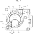
- FIG. 7 illustrates an inlet shutter 14 located in a blocking position.
- FIG. 8 illustrates the inlet shutter 14 located in an inlet position.
- an upper body 13 is omitted.
- the toner refilling portion 10 may include a mounting portion 11 in which the toner cartridge 9 is mounted, a toner inlet portion 120 , and the inlet shutter 14 .
- the mounting portion 11 is connected to the toner container 230 .
- the toner cartridge 9 that is inserted from outside the mounting portion 11 through the communicating portion 8 is mounted in the mounting portion 11 .
- the toner inlet portion 120 is provided in the mounting portion 11 to receive toner from the toner cartridge 9 .
- the mounting portion 11 may include a lower body 12 and an upper body 13 .
- the upper body 13 is coupled to the lower body 12 .
- the lower body 12 is connected to the toner container 230 .
- the toner inlet portion 120 is provided in the lower body 12 .
- the inlet shutter 14 is provided in the mounting portion 11 such that it is switchable between a blocking position ( FIG. 7 ) where the toner inlet portion 120 is blocked and an inlet position ( FIG. 8 ) where the toner inlet portion 120 is opened.
- the inlet shutter 14 may be rotated about a first rotational axis C 1 to be switched between the blocking position and the inlet position.
- the inlet shutter 14 may include a blocking portion 140 .
- the inlet shutter 14 may be provided in the mounting portion 11 such that the inlet shutter 14 is rotatable about the first rotational axis C 1 between the blocking position ( FIG. 7 ) where the blocking portion 140 blocks the toner inlet portion 120 and the inlet position ( FIG. 8 ) where the blocking portion 140 is offset from the toner inlet portion 120 to open the toner inlet portion 120 .
- the inlet shutter 14 may be located between the lower body 12 and the upper body 13 .
- the inlet shutter 14 may be rotatably supported by the lower body 12 .
- a first cylindrical portion 122 that rotatably supports the inlet shutter 14 about the first rotational axis C 1 is provided in the lower body 12 .
- the first cylindrical portion 122 may be implemented using, for example, a cylindrical rib arranged about the first rotational axis C 1 and protruding toward the upper body 13 .
- the inlet shutter 14 includes a second cylindrical portion 142 surrounding the first cylindrical portion 122 and being rotatably supported by the first cylindrical portion 122 .
- the upper body 13 is coupled to the lower body 12 to cover the inlet shutter 14 .
- the inlet shutter 14 includes a receiving portion 143 receiving the front end portion of the toner cartridge 9 .
- the inlet shutter 14 has a shape that is rotatable with the toner cartridge 9 when the toner cartridge 9 is rotated about the first rotational axis C 1 .
- a shape of the front end portion of the toner cartridge 9 may be complementary to a shape of the blocking portion 140 .
- a groove 143 - 1 that is partially opened and protrudes outwardly to receive a protruding portion 912 of the toner cartridge 9 may be formed in the receiving portion 143 .
- An insertion portion 135 and a key groove 135 - 1 that are respectively aligned with the receiving portion 143 and the groove 143 - 1 may be provided in the upper body 13 .
- the receiving portion 143 , the groove 143 - 1 , the insertion portion 135 , and the key groove 135 - 1 are aligned with each other when the inlet shutter 14 is located in the blocking position.
- the toner cartridge 9 may be mounted in the mounting portion 11 . Then the front end portion of the body 91 is received in the receiving portion 143 of the inlet shutter 14 , and the protruding portion 912 is received in the groove 143 - 1 , and the front end portion of the toner cartridge 9 and the blocking portion 140 are coupled to each other in a complementary manner.
- the blocking portion 140 covers the toner inlet portion 120 .
- the toner discharging portion 940 of the toner cartridge 9 is located in an offset position from the toner inlet portion 120 . The toner discharging portion 940 is blocked by the discharge shutter 95 illustrated in FIG. 4 .
- the inlet shutter 14 is rotated with the toner cartridge 9 . Accordingly, the inlet shutter 14 may be rotated between the blocking position and the inlet position.
- the protruding portion 912 is located in a lower portion of a boundary of the insertion portion 135 of the upper body 13 . In this state, even when attempting to forcibly separate the toner cartridge 9 from the mounting portion 11 , since the protruding portion 912 is caught by the insertion portion 135 , the toner cartridge 9 is not separated.
- the inlet shutter 14 When the toner cartridge 9 is rotated about the first rotational axis C 1 by 180 degrees, as illustrated in FIG. 8 , the inlet shutter 14 is in the inlet position, and the blocking portion 140 is offset from the toner inlet portion 120 , thereby opening the toner inlet portion 120 .
- the discharge shutter 95 is caught by an outer portion of the toner inlet portion 120 and is thus not rotated, and the body 91 , on the other hand, is rotated with respect to the discharge shutter 95 by 180 degrees.
- the toner discharging portion 940 of the toner cartridge 9 is opened, and the toner discharging portion 940 is aligned with the toner inlet portion 120 .
- toner may be supplied from the body 91 to the toner container 230 through the toner discharging portion 940 and the toner inlet portion 120 .
- the development cartridge 2 is an integration-type development cartridge 2 in which the toner refilling portion 10 is integrated, as illustrated in FIG. 3 .
- the development cartridge 2 may be distributed during the product distribution stage while being mounted in the main body 1 .
- the development cartridge 2 is a consumable item that is replaced when the life of the development cartridge 2 ends, and may be distributed separately from the main body 1 .
- toner inlet portion 120 is opened in a distribution stage, toner contained in the toner container 230 may leak out. The leaked toner may contaminate the toner refilling portion 10 .
- the toner inlet portion 120 is opened during the distribution stage where the development cartridge 2 is distributed while being mounted in the main body 1 , the inside of the main body 1 may be contaminated by the leaked toner.
- the printer according to the present example includes a first latch member 16 having a first position where the inlet shutter 14 is locked and a second position where switching of the inlet shutter 14 is allowed.
- a switching unit 18 which will be described later, selectively switches the first latch member 16 between the first position and the second position.
- the first latch member 16 is provided in the toner refilling portion 10
- the switching unit 18 is provided in the main body 1 .
- the first latch member 16 may be provided in the mounting portion 11 such that the first latch member 16 is switched between the first position and the second position.
- the first latch member 16 may be moved in a direction of the first rotational axis C 1 to be switched between the first position and the second position.
- an operation hole 123 extending in a direction of the first rotational axis C 1 may be formed in the lower body 12 .
- the first latch member 16 may be movably inserted into the operation hole 123 in a direction of the first rotational axis C 1 .
- a first latch spring 17 applies an elastic force to the first latch member 16 in a direction in which the first latch spring 17 is located in the first position.
- the first latch spring 17 may be in various forms such as a coil spring, a leaf spring, or a resilient arm integrally formed with the first latch member 16 .
- the first latch spring 17 may be implemented by a compression coil spring having a first end portion supported by the upper body 13 and a second end portion supported by the first latch member 16 .
- the first latch member 16 may lock the inlet shutter 14 in the blocking position.
- a first latching portion 144 is provided in the inlet shutter 14 .
- the first latching portion 144 may be implemented by a pair of protrusions 144 - 1 and 144 - 2 that protrude outward from an outer circumference of the inlet shutter 14 and are spaced apart from each other in a circumferential direction.
- the first latch member 16 may include a latching protrusion 161 which is caught by the first latching portion 144 when the first latch member 16 is located in the first position. Referring to FIG.
- the latching protrusion 161 of the first latch member 16 located in the first position is caught by the first latching portion 144 , and the inlet shutter 14 is locked in the blocking position.
- the first latch member 16 may be held in the first position via the first latch spring 17 when the development cartridge 2 is separated from the main body 1 .
- the toner inlet portion 120 may be maintained in a closed state, and thus, toner leakage may be prevented.
- the inlet shutter 14 When the toner cartridge 9 is mounted in the mounting portion 11 and is rotated during refilling of toner, the inlet shutter 14 is also rotated so that the toner inlet portion 120 and the toner discharging portion 940 may be offset from each other. Then, the toner discharged through the toner discharging portion 940 may leak out of the toner inlet portion 120 to contaminate the toner refilling portion 10 .
- the first latch member 16 may lock the inlet shutter 14 in the inlet position.
- a second latching portion 145 is provided on the inlet shutter 14 .
- the second latching portion 145 may be implemented using a pair of protrusions 145 - 1 and 145 - 2 that protrude outwardly from the outer circumference of the inlet shutter 14 and are spaced apart from each other in a circumferential direction.
- the latching protrusion 161 of the first latch member 16 located in the first position is caught by the second latching portion 145 , and the inlet shutter 14 is locked in the inlet position. Accordingly, while the toner cartridge 9 is mounted in the mounting portion 11 and toner is being refilled, the inlet shutter 14 is not rotated, and the toner may be stably refilled in the toner container 230 without toner leakage.
- the switching unit 18 selectively switches the first latch member 16 between the first position and the second position. For example, while the inlet shutter 14 is locked in the blocking position, when the toner cartridge 9 is mounted in the toner refilling portion 10 , the switching unit 18 switches the first latch member 16 to the second position so that the inlet shutter 14 and the toner cartridge 9 may be rotated together. When the first latch member 16 is located in the second position, the latching protrusion 161 deviates from the first latching portion 144 , and the inlet shutter 14 enters a state where it is rotatable.
- the switching unit 18 may switch the first latch member 16 to the first position.
- the latching protrusion 161 of the first latch member 16 is caught by the second latching portion 145 and the inlet shutter 14 is locked in the inlet position, and thus the toner cartridge 9 and the inlet shutter 14 are not rotated.
- FIG. 9 is a schematic structural diagram of the switching unit 18 according to an example, showing the first latch member 16 located in the first position.
- FIG. 10 is a schematic structural diagram of the switching unit 18 according to an example, showing the first latch member 16 located in the second position.
- FIG. 11 illustrates a structure of detecting a phase of a rotational cam 181 according to an example.
- the upper body 13 is omitted.
- the switching unit 18 includes a rotational cam 181 having a cam track 181 a , a motor 182 rotating the rotational cam 181 , and a movable member 183 guided to the cam track 181 a to switch the first latch member 16 between the first and second positions.
- the cam track 181 a may include first and second cam portions 181 a - 1 and 181 a - 2 respectively corresponding to the first and second positions of the first latch member 16 .
- the movable member 183 may include a first movable member 183 - 1 guided to the cam track 181 a to be pivoted and a second movable member 183 - 2 connected to the first movable member 183 - 1 to be lifted.
- the second movable member 183 - 2 When the development cartridge 2 is mounted in the main body 1 , the second movable member 183 - 2 may be inserted into the operation hole 123 in which the first latch member 16 is installed, to thereby contact the first latch member 16 .
- the cam spring 184 applies an elastic force to the movable member 183 in a direction in which the movable member 183 contacts the cam track 181 a .
- the cam spring 184 is implemented by using a tensile coil spring having a first end portion connected to the first movable member 183 - 1 and a second end portion supported by the main body 1 . The first end portion of the first movable member 183 - 1 is maintained in contact with the cam track 181 a via the cam spring 184 .
- the motor 182 may be, for example, a direct current (DC) motor.
- a worm gear may be mounted on a rotational axis of the motor 182 .
- a worm wheel with which the worm gear engages may be provided to the rotational cam 181 .
- the rotational cam 181 may be rotated.
- the switching unit 18 may further include a sensor 185 detecting a phase of the rotational cam 181 .
- the sensor 185 may be implemented using a photo-interrupter including a light emitting portion 185 - 1 and a light receiving portion 185 - 2 .
- a light shielding rib 181 b blocking light between the light emitting portion 185 - 1 and the light receiving portion 185 - 2 according to a rotational phase may be provided in the rotational cam 181 .
- an ON detection signal may be generated in the light receiving portion 185 - 2 ; when light is detected from the light receiving portion 185 - 2 , an OFF detection signal may be generated in the light receiving portion 185 - 2 .
- the movable member 183 may be configured to be guided to the first cam portion 181 a - 1 of the rotational cam 181 in a moment when a detection signal of the light receiving portion 185 - 2 changes from ON to OFF, and the movable member 183 may be configured to be guided to the second cam portion 181 a - 2 of the rotational cam 181 in a moment when a detection signal of the light receiving portion 185 - 2 changes from OFF to ON.
- a rotational phase of the rotational cam 181 may be detected, and the first latch member 16 may be positioned in the first position or the second position.
- the motor 182 is driven in an initial state and stopped a moment when a detection signal of the light receiving portion 185 - 2 changes from ON to OFF. Then the movable member 183 is guided to the first cam portion 181 a - 1 , and the movable member 183 moves away from the first latch member 16 , and accordingly, due to an elastic force of the first latch spring 17 , the first latch member 16 is located in the first position as illustrated in FIG. 9 . As the latching protrusion 161 of the first latch member 16 is caught by the first latching portion 144 or the second latching portion 145 of the inlet shutter 14 , the inlet shutter 14 is locked in the blocking position or the inlet position.
- the motor 182 is driven and then stopped a moment when a detection signal of the light receiving portion 185 - 2 changes from OFF to ON. Then the movable member 183 is guided to the second cam portion 181 a - 2 , and the movable member 183 pushes the first latch member 16 in an opposite direction to the elastic force of the first latch spring 17 . Then, as illustrated in FIG. 10 , the first latch member 16 is located in the second position.
- the inlet shutter 14 may be rotated from the blocking position to the inlet shutter 14 or in an opposite direction thereto.
- FIG. 12 is a perspective view of a structure in which the first latch member 16 and the switching unit 18 are provided in the main body 1 , according to an example.
- FIG. 13 is an exploded perspective view of the structure of FIG. 12 .
- FIG. 14 illustrates the inlet shutter 14 located in the blocking position.
- FIG. 15 illustrates the inlet shutter 14 located in the inlet position.
- FIG. 16 is a schematic perspective view of the toner cartridge 9 according to an example. In FIGS. 12 and 13 , only the toner refilling portion 10 , the first latch member 16 , and the switching unit 18 are illustrated. In FIGS. 14 and 15 , the upper body 13 is omitted. Elements having an identical function as those described in the above-described examples will be labeled with identical reference numerals.
- the toner cartridge 9 may be a syringe-type toner refill cartridge including a body 91 containing toner and including a toner discharging portion 940 and a plunger 93 that is movably coupled to the body 91 in a length direction A to pull the toner out of the body 91 .
- the toner discharging portion 940 may be provided at a front end portion of the body 91 .
- the toner discharging portion 940 may be eccentrically positioned from the first rotational axis C 1 .
- the body 91 may be, for example, cylindrical.
- the first rotational axis C 1 may be a central axis of a cylindrical body 91 .
- the first rotational axis C 1 may be a rotational central axis about which the toner cartridge 9 mounted on the toner refilling portion 10 is rotated.
- a discharge shutter (not shown) selectively opens or closes the toner discharging portion 940 .
- the toner refilling portion 10 may include a mounting portion 11 in which the toner cartridge 9 is mounted, a toner inlet portion 120 , and an inlet shutter 14 .
- the mounting portion 11 is connected to the toner container 230 .
- the toner cartridge 9 that is inserted from outside the mounting portion 11 through the communicating portion 8 is mounted in the mounting portion 11 .
- a toner inlet portion 120 is provided in the mounting portion 11 to receive toner from the toner cartridge 9 .
- the mounting portion 11 may include a lower body 12 and an upper body 13 .
- the upper body 13 is coupled to the lower body 12 .
- the lower body 12 is connected to the toner container 230 .
- the toner inlet portion 120 is provided in the lower body 12 .
- the inlet shutter 14 is provided in the mounting portion 11 such that the inlet shutter 14 is switchable between the blocking position ( FIG. 14 ) where the toner inlet portion 120 is blocked and the inlet position ( FIG. 15 ) where the toner inlet portion 120 is opened.
- the inlet shutter 14 may be rotated about the first rotational axis C 1 between the blocking position and the inlet position.
- the inlet shutter 14 may include a second toner inlet portion 141 .
- the inlet shutter 14 may be provided in the mounting portion 11 such that the inlet shutter 14 is rotatable about the first rotational axis C 1 between the blocking position where the toner inlet portion 120 and the second toner inlet portion 141 are offset from each other to block the toner inlet portion 120 and the inlet position where the toner inlet portion 120 and the second toner inlet portion 141 are aligned with each other to open the toner inlet portion 120 .
- the second toner inlet portion 141 is aligned with the toner discharging portion 940 of the toner cartridge 9 .
- the inlet shutter 14 may be located between the lower body 12 and the upper body 13 .
- the inlet shutter 14 may be rotatably supported by the lower body 12 .
- the lower body 12 has a first cylindrical portion 122 that rotatably supports the inlet shutter 14 about the first rotational axis C 1 .
- the first cylindrical portion 122 may be, for example, a cylindrical rib arranged about the first rotational axis C 1 and protruding toward the upper body 13 .
- the inlet shutter 14 is supported by the lower body 12 such that the second cylindrical portion 142 forming an outer circumference of the inlet shutter 14 is located within the first cylindrical portion 122 .
- the upper body 13 is coupled to the lower body 12 to cover the inlet shutter 14 .
- the upper body 13 may have a structure in which the toner cartridge 9 may be rotatably supported.
- a receiving portion 132 having a cylindrical shape and receiving the front end portion of the toner cartridge 9 may be provided in the upper body 13 .
- the receiving portion 132 may be, for example, a cylindrical rib arranged about the first rotational axis C 1 and protruding upwardly.
- the toner cartridge 9 is mounted in the mounting portion 11 .
- the toner discharging portion 940 is inserted into the second toner inlet portion 141 .
- the second toner inlet portion 141 and the toner inlet portion 120 are offset from each other, even when a discharge shutter opens the toner discharging portion 940 , toner does not flow into the toner inlet portion 120 .
- the toner cartridge 9 is rotated about the first rotational axis C 1 by 90 degrees, as illustrated in FIG.
- the inlet shutter 14 is in the inlet position, and the second toner inlet portion 141 is aligned with the toner inlet portion 120 , thereby opening the toner inlet portion 120 .
- the discharge shutter (not shown) opens the toner discharging portion 940 and presses the plunger 93 , toner may be supplied to the toner container 230 from the body 91 through the toner discharging portion 940 , the second toner inlet portion 141 , and the toner inlet portion 120 .
- the printer according to the present example includes the first latch member 16 having a first position where the inlet shutter 14 is locked and a second position where switching of the inlet shutter 14 is allowed.
- the switching unit 18 selectively switches the first latch member 16 between the first position and the second position.
- the first latch member 16 and the switching unit 18 are provided in the main body 1 .
- the first latch member 16 may be moved in a direction of the first rotational axis C 1 to be switched between the first position and the second position.
- the first latch member 16 is inserted, for example, into a through hole 124 provided in the lower body 12 .
- the first latch member 16 may lock the inlet shutter 14 in the blocking position.
- a first latching portion 144 whereby the first latch member 16 located in the first position is caught when the inlet shutter 14 is located in the blocking position is provided in the inlet shutter 14 .
- the first latching portion 144 is aligned with the first latch member 16 , and when the first latch member 16 is switched to the first position via the switching unit 18 which will be described later, the first latch member 16 may be caught by the first latching portion 144 , thereby locking the inlet shutter 14 in the blocking position.
- the toner inlet portion 120 may be maintained in a closed state, and thus, toner leakage may be prevented.
- the first latch member 16 may lock the inlet shutter 14 in the inlet position.
- the second latching portion 145 whereby the first latch member 16 located in the first position is caught when the inlet shutter 14 is located in the inlet position is provided in the inlet shutter 14 .
- the second latching portion 145 is aligned with the first latch member 16 , and when the first latch member 16 is switched to the first position via the switching unit 18 which will be described later, the first latch member 16 may be caught by the second latching portion 145 , thereby locking the inlet shutter 14 in the inlet position. Accordingly, while the toner cartridge 9 is mounted in the mounting portion 11 and toner is being refilled, the inlet shutter 14 is not rotated, and the toner may be stably refilled in the toner container 230 without toner leakage.
- the switching unit 18 may include a solenoid 186 via which the first latch member 16 is switched between the first and second positions.
- the solenoid 186 may include a solenoid body 186 - 1 and a driving shaft 186 - 2 .
- the first latch member 16 is connected to the driving shaft 186 - 2 .
- a first latch spring 17 applies an elastic force to the first latch member 16 in a direction in which the first latch member 16 is located in the first position.
- the first latch spring 17 is implemented by a compression coil spring interposed between the driving shaft 186 - 2 and the solenoid body 186 - 1 .
- the first latch spring 17 applies an elastic force to the driving shaft 186 - 2 in a direction in which the first latch member 16 is located in the first position. That is, the first latch spring 17 pushes the driving shaft 186 - 2 towards the first latch member 16 .
- the driving shaft 186 - 2 When a current is supplied to the solenoid body 186 - 1 , the driving shaft 186 - 2 is pulled in an opposite direction of the elastic force of the first latch spring 17 , that is, toward the solenoid body 186 - 1 . The first latch member 16 is moved from the first position to the second position. When no current is applied to the solenoid body 186 - 1 , the driving shaft 186 - 2 is pushed toward the first latch member 16 due to the elastic force of the first latch spring 17 and the first latch member 16 is moved from the second position to the first position.
- the switching unit 18 including the solenoid 186 by supplying or blocking a current to or from the solenoid 186 , the first latch member 16 may be switched between the second position and the first position.
- a third latching portion 146 may be provided in the inlet shutter 14 .
- a second latch member 19 has a third position where the second latch member 19 is caught by the third latching portion 146 when the inlet shutter 14 is located in the blocking position to lock the inlet shutter 14 and a fourth position where the second latch member 19 is released from the third latching portion 146 .
- the second latch member 19 may be liftably mounted in a direction of the first rotational axis C 1 in the operation hole 125 of the lower body 12 that extends in a direction of the first rotational axis C 1 .
- the third latching portion 146 may be concavely formed in an upward direction from a lower surface of the inlet shutter 14 .
- a latching portion 191 that is caught by the third latching portion 146 when the second latch member 19 is located in the third position is formed on the second latch member 19 .
- a second latch spring 20 applies an elastic force to the second latch member 19 in a direction in which the second latch member 19 is located in the third position.
- the inlet shutter 14 may not be locked in the blocking position.
- the inlet shutter 14 may not be locked in the blocking position. According to the present example, when the development cartridge 2 is separated from the main body 1 , the inlet shutter 14 may be locked in the blocking position via the second latch member 19 .
- FIG. 17 is a partial perspective view of a structure of switching the second latch member 19 to the fourth position, according to an example.
- the second latch member 19 protrudes upwardly from the upper body 13 through a through hole 136 formed in the upper body 13 .
- the door 3 is provided in the main body 1 to open or close a portion of the main body 1 to attach/detach the development cartridge 2 to/from the main body 1 . According to the present example, the door 3 partially opens an upper portion of the main body 1 .
- a releasing member 31 that switches the second latch member 19 to the fourth position via a closing operation of the door 3 is provided in the door 3 .
- the releasing member 31 may be protruded from an inner surface of the door 3 and press the second latch member 19 in an opposite direction to the elastic force of the second latch spring 20 when the door 3 is closed, thereby switching the second latch member 19 to the fourth position.
- the releasing member 31 is spaced apart from the second latch member 19 , and the second latch member 19 may return from the fourth position to the third position via the elastic force of the second latch spring 20 and be maintained in the third position.
- the inlet shutter 14 may be locked in the blocking position via the second latch member 19 .
- the releasing member 31 presses the second latch member 19 via a closing operation of the development cartridge 2 , thereby switching the second latch member 19 to the fourth position.
- the inlet shutter 14 may be locked in the blocking position or the inlet position, and rotated from the blocking position to the inlet shutter 14 or in an opposite direction thereto.
Landscapes
- Physics & Mathematics (AREA)
- General Physics & Mathematics (AREA)
- Life Sciences & Earth Sciences (AREA)
- Sustainable Development (AREA)
- Engineering & Computer Science (AREA)
- Computer Vision & Pattern Recognition (AREA)
- Dry Development In Electrophotography (AREA)
Abstract
Description
Claims (15)
Applications Claiming Priority (3)
| Application Number | Priority Date | Filing Date | Title |
|---|---|---|---|
| KR1020180102539A KR20200025336A (en) | 2018-08-30 | 2018-08-30 | Structure for selectively locking toner inlet shutter of toner refill portion |
| KR10-2018-0102539 | 2018-08-30 | ||
| PCT/US2019/020769 WO2020046421A1 (en) | 2018-08-30 | 2019-03-05 | Structure for selectively locking toner inlet shutter of toner refill portion |
Publications (2)
| Publication Number | Publication Date |
|---|---|
| US20210088939A1 US20210088939A1 (en) | 2021-03-25 |
| US11209754B2 true US11209754B2 (en) | 2021-12-28 |
Family
ID=69645313
Family Applications (1)
| Application Number | Title | Priority Date | Filing Date |
|---|---|---|---|
| US17/050,337 Active US11209754B2 (en) | 2018-08-30 | 2019-03-05 | Structure for selectively locking toner inlet shutter of toner refill portion |
Country Status (5)
| Country | Link |
|---|---|
| US (1) | US11209754B2 (en) |
| EP (1) | EP3765909B1 (en) |
| KR (1) | KR20200025336A (en) |
| CN (1) | CN112449689B (en) |
| WO (1) | WO2020046421A1 (en) |
Cited By (1)
| Publication number | Priority date | Publication date | Assignee | Title |
|---|---|---|---|---|
| US20220187735A1 (en) * | 2020-12-11 | 2022-06-16 | Canon Kabushiki Kaisha | Image forming apparatus |
Families Citing this family (6)
| Publication number | Priority date | Publication date | Assignee | Title |
|---|---|---|---|---|
| BR112020015528A2 (en) * | 2018-01-31 | 2021-02-02 | Hewlett-Packard Development Company, L.P. | impression substance end-of-life predictions |
| KR20200025331A (en) * | 2018-08-30 | 2020-03-10 | 휴렛-팩커드 디벨롭먼트 컴퍼니, 엘.피. | Shutter structure for toner refill cartridge |
| EP3940460A4 (en) * | 2019-03-15 | 2022-12-14 | Canon Kabushiki Kaisha | IMAGE FORMING DEVICE |
| KR20210153283A (en) | 2020-06-10 | 2021-12-17 | 휴렛-팩커드 디벨롭먼트 컴퍼니, 엘.피. | toner cartridge having front cover |
| KR20220013674A (en) * | 2020-07-27 | 2022-02-04 | 휴렛-팩커드 디벨롭먼트 컴퍼니, 엘.피. | structure to lock toner refill cartridge to mounting portion in connection with inlet shutter |
| JP7562379B2 (en) | 2020-11-10 | 2024-10-07 | キヤノン株式会社 | Image forming apparatus and image forming system |
Citations (78)
| Publication number | Priority date | Publication date | Assignee | Title |
|---|---|---|---|---|
| US3599682A (en) * | 1968-08-30 | 1971-08-17 | Eastman Kodak Co | Loading mechanism |
| US3651838A (en) * | 1970-12-15 | 1972-03-28 | Eastman Kodak Co | Loading mechanism improvement |
| US4237943A (en) * | 1978-04-22 | 1980-12-09 | Agfa-Gevaert, A.G. | Tuner supply for electrostatic copiers |
| US4307763A (en) * | 1979-11-29 | 1981-12-29 | International Business Machines Corporation | Toner container |
| US4456154A (en) * | 1982-08-16 | 1984-06-26 | Xerox Corporation | Toner loading cartridge |
| US4489765A (en) * | 1981-07-22 | 1984-12-25 | Konishiroku Photo Industry Co., Ltd. | Method of supplying a fine-particle powder |
| US4963939A (en) * | 1986-09-24 | 1990-10-16 | Mita Industrial Co., Ltd. | Cartridge discriminating system |
| US5075724A (en) * | 1988-08-26 | 1991-12-24 | Minolta Camera Kabushiki Kaisha | System for recognizing interchangeable articles |
| US5079591A (en) * | 1989-06-09 | 1992-01-07 | Ricoh Company, Ltd. | Toner cartridge with an inner sack which is perforated when the cartridge is isnerted |
| US5089854A (en) * | 1990-02-19 | 1992-02-18 | Shozo Kaieda | Apparatus for supplementing developing agent into image forming machine |
| US5091750A (en) * | 1989-12-08 | 1992-02-25 | Mita Industrial Co., Ltd. | Cartridge unit |
| US5150807A (en) * | 1991-09-04 | 1992-09-29 | Xerox Corporation | Apparatus for storing marking particles |
| JPH0862979A (en) | 1994-03-03 | 1996-03-08 | Kyocera Corp | Image forming device |
| US5614996A (en) * | 1994-03-03 | 1997-03-25 | Kyocera Corporation | Toner storage unit, residual toner collect unit, toner container with these units and image forming apparatus with such toner container |
| JPH1020647A (en) * | 1996-07-03 | 1998-01-23 | Canon Inc | Process cartridge, toner cartridge, toner hopper, and image forming apparatus |
| US5802431A (en) * | 1995-04-03 | 1998-09-01 | Canon Kabushiki Kaisha | Collapsible toner container |
| US5848338A (en) * | 1997-01-17 | 1998-12-08 | Mita Industrial Co., Ltd. | Toner replenishing device and toner cartridge for use therein |
| US5887232A (en) * | 1995-12-08 | 1999-03-23 | Hewlett-Packard Company | Apparatus for dispensing toner in an electrophotographic printing system |
| US5995782A (en) | 1996-09-30 | 1999-11-30 | Canon Kabushiki Kaisha | Developing cartridge with mounting positioning feature and image forming apparatus using the same |
| US6212338B1 (en) * | 1999-03-30 | 2001-04-03 | Sharp Kabushiki Kaisha | Image forming device with communication to supplementary toner container |
| US6249654B1 (en) * | 1999-09-29 | 2001-06-19 | Xerox Corporation | Refillable all-in-one print cartridge/toner bottle strategy |
| US6266506B1 (en) * | 1999-09-29 | 2001-07-24 | Xerox Corporation | Mechanical keying concept for refillable print cartridge/toner bottle strategy |
| US6304739B1 (en) * | 1998-10-19 | 2001-10-16 | Ricoh Company, Ltd. | Toner container and image forming apparatus using the same |
| US20010041083A1 (en) * | 1998-12-22 | 2001-11-15 | Seiji Terazawa | Toner container and image forming method and apparatus using the same |
| US20020009310A1 (en) * | 2000-07-21 | 2002-01-24 | Ricoh Company, Ltd. | Color image forming apparatus, toner replenishing apparatus, and toner container |
| US20020039502A1 (en) * | 2000-09-28 | 2002-04-04 | Junichi Matsumoto | Toner supply unit and image forming apparatus |
| US6393241B1 (en) * | 1999-09-30 | 2002-05-21 | Ricoh Company, Ltd. | Nozzle having an end portion capable of penetrating into a toner discharging portion included in a toner container that stores powdery toner |
| US6571076B2 (en) * | 2000-03-10 | 2003-05-27 | Ricoh Company, Ltd. | Image forming apparatus and toner container therefor |
| US20030118355A1 (en) * | 2001-12-21 | 2003-06-26 | Xerox Corporation | Container configuration matching system |
| US6598625B2 (en) * | 2001-10-29 | 2003-07-29 | Hewlett-Packard Development Company, L.P. | Internal printer ink tank adapted for better space efficiency |
| US20030170049A1 (en) * | 2002-01-31 | 2003-09-11 | Fumihito Itoh | Toner refilling device and developing device using the same for an image forming apparatus |
| US6676252B2 (en) * | 2002-04-24 | 2004-01-13 | Hewlett-Packard Development Company, L.P. | Printer ink cartridge and method of assembling same |
| US20040037591A1 (en) * | 2002-05-24 | 2004-02-26 | Bernhard Schlageter | Method of and device for conveying toner material from a toner refill container as well as associated toner refill container |
| US20040040614A1 (en) * | 2002-09-04 | 2004-03-04 | Sesek Robert M. | Ink cartridge refilling station |
| US6813460B2 (en) * | 2001-01-31 | 2004-11-02 | Ricoh Company, Ltd. | Toner container and image forming apparatus using the same |
| US20050013633A1 (en) * | 2003-07-14 | 2005-01-20 | Fuji Xerox Co., Ltd. | Image forming device |
| US20050041998A1 (en) * | 2003-08-19 | 2005-02-24 | Konica Minolta Business Technologies, Inc. | Image forming apparatus |
| US6862420B1 (en) * | 2003-09-26 | 2005-03-01 | Xerox Corporation | Toner container cartridge and refilling apparatus |
| EP1548519A2 (en) * | 2003-12-23 | 2005-06-29 | Sagem SA | Cartridge system with toner reload and method therefor |
| US20050157117A1 (en) * | 2004-01-21 | 2005-07-21 | Silverbrook Research Pty Ltd | Inkjet printer cartridge refill dispenser with security lock for spent refill |
| US20050220481A1 (en) | 2004-02-20 | 2005-10-06 | Canon Kabushiki Kaisha | Process cartridge and image forming apparatus |
| US20060002743A1 (en) * | 2004-04-23 | 2006-01-05 | Goro Katsuyama | Apparatuses for image forming capable of effectively conveying developer therefrom and a method of effectively forming a reinforcing member adhering to the apparatuses |
| US20060104673A1 (en) * | 2004-11-12 | 2006-05-18 | Canon Kabushiki Kaisha | Developer supply container and image forming apparatus |
| US20060109320A1 (en) * | 2004-09-28 | 2006-05-25 | Cutler Clayton R | Inkjet cartridge refilling machine and method |
| US20060263116A1 (en) * | 2003-04-25 | 2006-11-23 | Goro Katsuyama | Storage vessel and image forming device |
| US20070003325A1 (en) | 2005-06-29 | 2007-01-04 | Samsung Electronics Co., Ltd. | Developer filling apparatus and developer filling system having the same |
| US20070116494A1 (en) * | 2005-11-09 | 2007-05-24 | Mugijirou Uno | Image forming method and apparatus for effectively supplying developer |
| US7300130B2 (en) * | 2003-07-11 | 2007-11-27 | Hewlett-Packard Development Company, L.P. | Print cartridge temperature control |
| US20080025743A1 (en) * | 2006-07-31 | 2008-01-31 | Eisuke Hori | Powder conveying device, developing device, process cartridge, and image forming apparatus |
| EP2102715A1 (en) | 2006-12-08 | 2009-09-23 | Canon Kabushiki Kaisha | Process cartridge and electrophotographic image forming apparatus |
| US20090277911A1 (en) * | 2007-03-01 | 2009-11-12 | Satoshi Koide | Packaging method and packaging container |
| US20090297226A1 (en) * | 2005-03-04 | 2009-12-03 | Canon Kabushiki Kaisha | Developer supply container and developer receiving apparatus |
| US20100092216A1 (en) * | 2008-10-14 | 2010-04-15 | Xerox Corporation | Telescopic auger dispense drop tube |
| US7831190B2 (en) | 2007-07-04 | 2010-11-09 | Samsung Electronics Co., Ltd. | Cover opening and closing unit, image forming apparatus having the same, and method of removing and mounting cover |
| US20110097094A1 (en) * | 2009-10-26 | 2011-04-28 | Hamano Toshihiro | Developer transport unit, image forming apparatus, method of transporting developer, program for transporting developer, and storage medium storing the program |
| US7959270B2 (en) * | 2005-12-23 | 2011-06-14 | Xerox Corporation | Collapsible packaging system |
| US20110217067A1 (en) * | 2010-03-03 | 2011-09-08 | Kabushiki Kaisha Toshiba | Toner cartridge |
| US20120177406A1 (en) * | 2011-01-11 | 2012-07-12 | Ricoh Company, Limited | Toner container and image forming apparatus |
| US20120269540A1 (en) * | 2011-04-22 | 2012-10-25 | Canon Kabushiki Kaisha | Manufacturing method of developing device, remanufacturing method of process cartridge, developing device and process cartridge |
| US8385772B2 (en) | 2009-08-28 | 2013-02-26 | Samsung Electronics Co., Ltd. | Detachable toner cartridge and image forming apparatus including the same |
| US20130243445A1 (en) * | 2012-03-13 | 2013-09-19 | Ricoh Company, Ltd. | Image forming apparatus |
| US20140169838A1 (en) | 2005-03-04 | 2014-06-19 | Canon Kabushiki Kaisha | Developer supply container and developer supplying system |
| US20140227008A1 (en) * | 2011-10-19 | 2014-08-14 | Oce-Technologies B.V. | Toner refill device |
| US8929776B2 (en) * | 2012-02-17 | 2015-01-06 | Ricoh Company, Ltd. | Nozzle, image forming apparatus, and method of deriving powder |
| US20150063865A1 (en) * | 2013-08-30 | 2015-03-05 | Yuusuke Furuichi | Toner container, process cartridge, and image forming apparatus |
| US20160109827A1 (en) * | 2013-05-30 | 2016-04-21 | Tomofumi Yoshida | Toner container, process cartridge, and image forming apparatus |
| US9360799B2 (en) * | 2011-09-06 | 2016-06-07 | Brother Kogyo Kabushiki Kaisha | Toner filling apparatus |
| US20160313670A1 (en) * | 2015-04-27 | 2016-10-27 | Kyocera Document Solutions Inc. | Developer supplier, developing device including the same, image forming apparatus, and developer container included in the developer supplier |
| US20160357126A1 (en) * | 2015-06-05 | 2016-12-08 | Samsung Electronics Co., Ltd. | Developer cartridge and electrophotographic image forming apparatus including the same |
| US20170153575A1 (en) * | 2015-12-01 | 2017-06-01 | Océ-Technologies B.V. | Refill adapter for coupling a toner bottle to a toner reservoir in a printing system and associated method |
| US20180059576A1 (en) | 2016-08-26 | 2018-03-01 | Brother Kogyo Kabushiki Kaisha | Developing apparatus having opening and shutter |
| US20200133180A1 (en) * | 2018-10-30 | 2020-04-30 | Sharp Kabushiki Kaisha | Toner cartridge extrusion device and image forming apparatus including the same |
| US20200307870A1 (en) * | 2019-03-26 | 2020-10-01 | Seiko Epson Corporation | Additive container |
| US20210103246A1 (en) * | 2019-10-07 | 2021-04-08 | Canon Kabushiki Kaisha | Image forming apparatus |
| US20210103242A1 (en) * | 2019-10-02 | 2021-04-08 | Canon Kabushiki Kaisha | Image forming apparatus |
| US20210103235A1 (en) * | 2019-10-03 | 2021-04-08 | Canon Kabushiki Kaisha | Image forming apparatus |
| US20210109460A1 (en) * | 2019-10-11 | 2021-04-15 | Canon Kabushiki Kaisha | Image forming apparatus |
| US11055038B2 (en) * | 2018-01-31 | 2021-07-06 | Hewlett-Packard Development Company, L.P. | Print substance end-of-life predictions |
Family Cites Families (3)
| Publication number | Priority date | Publication date | Assignee | Title |
|---|---|---|---|---|
| JP3869901B2 (en) * | 1996-03-05 | 2007-01-17 | キヤノン株式会社 | Developing cartridge and electrophotographic image forming apparatus |
| US6314262B1 (en) * | 1999-07-23 | 2001-11-06 | Sharp Kabushiki Kaisha | Toner supply system and toner cartridge |
| JP5634388B2 (en) * | 2011-12-16 | 2014-12-03 | キヤノンファインテック株式会社 | Developer supply container storage device, developer supply container, and image forming apparatus |
-
2018
- 2018-08-30 KR KR1020180102539A patent/KR20200025336A/en not_active Withdrawn
-
2019
- 2019-03-05 CN CN201980048296.5A patent/CN112449689B/en active Active
- 2019-03-05 US US17/050,337 patent/US11209754B2/en active Active
- 2019-03-05 WO PCT/US2019/020769 patent/WO2020046421A1/en not_active Ceased
- 2019-03-05 EP EP19854473.6A patent/EP3765909B1/en active Active
Patent Citations (78)
| Publication number | Priority date | Publication date | Assignee | Title |
|---|---|---|---|---|
| US3599682A (en) * | 1968-08-30 | 1971-08-17 | Eastman Kodak Co | Loading mechanism |
| US3651838A (en) * | 1970-12-15 | 1972-03-28 | Eastman Kodak Co | Loading mechanism improvement |
| US4237943A (en) * | 1978-04-22 | 1980-12-09 | Agfa-Gevaert, A.G. | Tuner supply for electrostatic copiers |
| US4307763A (en) * | 1979-11-29 | 1981-12-29 | International Business Machines Corporation | Toner container |
| US4489765A (en) * | 1981-07-22 | 1984-12-25 | Konishiroku Photo Industry Co., Ltd. | Method of supplying a fine-particle powder |
| US4456154A (en) * | 1982-08-16 | 1984-06-26 | Xerox Corporation | Toner loading cartridge |
| US4963939A (en) * | 1986-09-24 | 1990-10-16 | Mita Industrial Co., Ltd. | Cartridge discriminating system |
| US5075724A (en) * | 1988-08-26 | 1991-12-24 | Minolta Camera Kabushiki Kaisha | System for recognizing interchangeable articles |
| US5079591A (en) * | 1989-06-09 | 1992-01-07 | Ricoh Company, Ltd. | Toner cartridge with an inner sack which is perforated when the cartridge is isnerted |
| US5091750A (en) * | 1989-12-08 | 1992-02-25 | Mita Industrial Co., Ltd. | Cartridge unit |
| US5089854A (en) * | 1990-02-19 | 1992-02-18 | Shozo Kaieda | Apparatus for supplementing developing agent into image forming machine |
| US5150807A (en) * | 1991-09-04 | 1992-09-29 | Xerox Corporation | Apparatus for storing marking particles |
| JPH0862979A (en) | 1994-03-03 | 1996-03-08 | Kyocera Corp | Image forming device |
| US5614996A (en) * | 1994-03-03 | 1997-03-25 | Kyocera Corporation | Toner storage unit, residual toner collect unit, toner container with these units and image forming apparatus with such toner container |
| US5802431A (en) * | 1995-04-03 | 1998-09-01 | Canon Kabushiki Kaisha | Collapsible toner container |
| US5887232A (en) * | 1995-12-08 | 1999-03-23 | Hewlett-Packard Company | Apparatus for dispensing toner in an electrophotographic printing system |
| JPH1020647A (en) * | 1996-07-03 | 1998-01-23 | Canon Inc | Process cartridge, toner cartridge, toner hopper, and image forming apparatus |
| US5995782A (en) | 1996-09-30 | 1999-11-30 | Canon Kabushiki Kaisha | Developing cartridge with mounting positioning feature and image forming apparatus using the same |
| US5848338A (en) * | 1997-01-17 | 1998-12-08 | Mita Industrial Co., Ltd. | Toner replenishing device and toner cartridge for use therein |
| US6304739B1 (en) * | 1998-10-19 | 2001-10-16 | Ricoh Company, Ltd. | Toner container and image forming apparatus using the same |
| US20010041083A1 (en) * | 1998-12-22 | 2001-11-15 | Seiji Terazawa | Toner container and image forming method and apparatus using the same |
| US6212338B1 (en) * | 1999-03-30 | 2001-04-03 | Sharp Kabushiki Kaisha | Image forming device with communication to supplementary toner container |
| US6249654B1 (en) * | 1999-09-29 | 2001-06-19 | Xerox Corporation | Refillable all-in-one print cartridge/toner bottle strategy |
| US6266506B1 (en) * | 1999-09-29 | 2001-07-24 | Xerox Corporation | Mechanical keying concept for refillable print cartridge/toner bottle strategy |
| US6393241B1 (en) * | 1999-09-30 | 2002-05-21 | Ricoh Company, Ltd. | Nozzle having an end portion capable of penetrating into a toner discharging portion included in a toner container that stores powdery toner |
| US6571076B2 (en) * | 2000-03-10 | 2003-05-27 | Ricoh Company, Ltd. | Image forming apparatus and toner container therefor |
| US20020009310A1 (en) * | 2000-07-21 | 2002-01-24 | Ricoh Company, Ltd. | Color image forming apparatus, toner replenishing apparatus, and toner container |
| US20020039502A1 (en) * | 2000-09-28 | 2002-04-04 | Junichi Matsumoto | Toner supply unit and image forming apparatus |
| US6813460B2 (en) * | 2001-01-31 | 2004-11-02 | Ricoh Company, Ltd. | Toner container and image forming apparatus using the same |
| US6598625B2 (en) * | 2001-10-29 | 2003-07-29 | Hewlett-Packard Development Company, L.P. | Internal printer ink tank adapted for better space efficiency |
| US20030118355A1 (en) * | 2001-12-21 | 2003-06-26 | Xerox Corporation | Container configuration matching system |
| US20030170049A1 (en) * | 2002-01-31 | 2003-09-11 | Fumihito Itoh | Toner refilling device and developing device using the same for an image forming apparatus |
| US6676252B2 (en) * | 2002-04-24 | 2004-01-13 | Hewlett-Packard Development Company, L.P. | Printer ink cartridge and method of assembling same |
| US20040037591A1 (en) * | 2002-05-24 | 2004-02-26 | Bernhard Schlageter | Method of and device for conveying toner material from a toner refill container as well as associated toner refill container |
| US20040040614A1 (en) * | 2002-09-04 | 2004-03-04 | Sesek Robert M. | Ink cartridge refilling station |
| US20060263116A1 (en) * | 2003-04-25 | 2006-11-23 | Goro Katsuyama | Storage vessel and image forming device |
| US7300130B2 (en) * | 2003-07-11 | 2007-11-27 | Hewlett-Packard Development Company, L.P. | Print cartridge temperature control |
| US20050013633A1 (en) * | 2003-07-14 | 2005-01-20 | Fuji Xerox Co., Ltd. | Image forming device |
| US20050041998A1 (en) * | 2003-08-19 | 2005-02-24 | Konica Minolta Business Technologies, Inc. | Image forming apparatus |
| US6862420B1 (en) * | 2003-09-26 | 2005-03-01 | Xerox Corporation | Toner container cartridge and refilling apparatus |
| EP1548519A2 (en) * | 2003-12-23 | 2005-06-29 | Sagem SA | Cartridge system with toner reload and method therefor |
| US20050157117A1 (en) * | 2004-01-21 | 2005-07-21 | Silverbrook Research Pty Ltd | Inkjet printer cartridge refill dispenser with security lock for spent refill |
| US20050220481A1 (en) | 2004-02-20 | 2005-10-06 | Canon Kabushiki Kaisha | Process cartridge and image forming apparatus |
| US20060002743A1 (en) * | 2004-04-23 | 2006-01-05 | Goro Katsuyama | Apparatuses for image forming capable of effectively conveying developer therefrom and a method of effectively forming a reinforcing member adhering to the apparatuses |
| US20060109320A1 (en) * | 2004-09-28 | 2006-05-25 | Cutler Clayton R | Inkjet cartridge refilling machine and method |
| US20060104673A1 (en) * | 2004-11-12 | 2006-05-18 | Canon Kabushiki Kaisha | Developer supply container and image forming apparatus |
| US20140169838A1 (en) | 2005-03-04 | 2014-06-19 | Canon Kabushiki Kaisha | Developer supply container and developer supplying system |
| US20090297226A1 (en) * | 2005-03-04 | 2009-12-03 | Canon Kabushiki Kaisha | Developer supply container and developer receiving apparatus |
| US20070003325A1 (en) | 2005-06-29 | 2007-01-04 | Samsung Electronics Co., Ltd. | Developer filling apparatus and developer filling system having the same |
| US20070116494A1 (en) * | 2005-11-09 | 2007-05-24 | Mugijirou Uno | Image forming method and apparatus for effectively supplying developer |
| US7959270B2 (en) * | 2005-12-23 | 2011-06-14 | Xerox Corporation | Collapsible packaging system |
| US20080025743A1 (en) * | 2006-07-31 | 2008-01-31 | Eisuke Hori | Powder conveying device, developing device, process cartridge, and image forming apparatus |
| EP2102715A1 (en) | 2006-12-08 | 2009-09-23 | Canon Kabushiki Kaisha | Process cartridge and electrophotographic image forming apparatus |
| US20090277911A1 (en) * | 2007-03-01 | 2009-11-12 | Satoshi Koide | Packaging method and packaging container |
| US7831190B2 (en) | 2007-07-04 | 2010-11-09 | Samsung Electronics Co., Ltd. | Cover opening and closing unit, image forming apparatus having the same, and method of removing and mounting cover |
| US20100092216A1 (en) * | 2008-10-14 | 2010-04-15 | Xerox Corporation | Telescopic auger dispense drop tube |
| US8385772B2 (en) | 2009-08-28 | 2013-02-26 | Samsung Electronics Co., Ltd. | Detachable toner cartridge and image forming apparatus including the same |
| US20110097094A1 (en) * | 2009-10-26 | 2011-04-28 | Hamano Toshihiro | Developer transport unit, image forming apparatus, method of transporting developer, program for transporting developer, and storage medium storing the program |
| US20110217067A1 (en) * | 2010-03-03 | 2011-09-08 | Kabushiki Kaisha Toshiba | Toner cartridge |
| US20120177406A1 (en) * | 2011-01-11 | 2012-07-12 | Ricoh Company, Limited | Toner container and image forming apparatus |
| US20120269540A1 (en) * | 2011-04-22 | 2012-10-25 | Canon Kabushiki Kaisha | Manufacturing method of developing device, remanufacturing method of process cartridge, developing device and process cartridge |
| US9360799B2 (en) * | 2011-09-06 | 2016-06-07 | Brother Kogyo Kabushiki Kaisha | Toner filling apparatus |
| US20140227008A1 (en) * | 2011-10-19 | 2014-08-14 | Oce-Technologies B.V. | Toner refill device |
| US8929776B2 (en) * | 2012-02-17 | 2015-01-06 | Ricoh Company, Ltd. | Nozzle, image forming apparatus, and method of deriving powder |
| US20130243445A1 (en) * | 2012-03-13 | 2013-09-19 | Ricoh Company, Ltd. | Image forming apparatus |
| US20160109827A1 (en) * | 2013-05-30 | 2016-04-21 | Tomofumi Yoshida | Toner container, process cartridge, and image forming apparatus |
| US20150063865A1 (en) * | 2013-08-30 | 2015-03-05 | Yuusuke Furuichi | Toner container, process cartridge, and image forming apparatus |
| US20160313670A1 (en) * | 2015-04-27 | 2016-10-27 | Kyocera Document Solutions Inc. | Developer supplier, developing device including the same, image forming apparatus, and developer container included in the developer supplier |
| US20160357126A1 (en) * | 2015-06-05 | 2016-12-08 | Samsung Electronics Co., Ltd. | Developer cartridge and electrophotographic image forming apparatus including the same |
| US20170153575A1 (en) * | 2015-12-01 | 2017-06-01 | Océ-Technologies B.V. | Refill adapter for coupling a toner bottle to a toner reservoir in a printing system and associated method |
| US20180059576A1 (en) | 2016-08-26 | 2018-03-01 | Brother Kogyo Kabushiki Kaisha | Developing apparatus having opening and shutter |
| US11055038B2 (en) * | 2018-01-31 | 2021-07-06 | Hewlett-Packard Development Company, L.P. | Print substance end-of-life predictions |
| US20200133180A1 (en) * | 2018-10-30 | 2020-04-30 | Sharp Kabushiki Kaisha | Toner cartridge extrusion device and image forming apparatus including the same |
| US20200307870A1 (en) * | 2019-03-26 | 2020-10-01 | Seiko Epson Corporation | Additive container |
| US20210103242A1 (en) * | 2019-10-02 | 2021-04-08 | Canon Kabushiki Kaisha | Image forming apparatus |
| US20210103235A1 (en) * | 2019-10-03 | 2021-04-08 | Canon Kabushiki Kaisha | Image forming apparatus |
| US20210103246A1 (en) * | 2019-10-07 | 2021-04-08 | Canon Kabushiki Kaisha | Image forming apparatus |
| US20210109460A1 (en) * | 2019-10-11 | 2021-04-15 | Canon Kabushiki Kaisha | Image forming apparatus |
Cited By (2)
| Publication number | Priority date | Publication date | Assignee | Title |
|---|---|---|---|---|
| US20220187735A1 (en) * | 2020-12-11 | 2022-06-16 | Canon Kabushiki Kaisha | Image forming apparatus |
| US11624989B2 (en) * | 2020-12-11 | 2023-04-11 | Canon Kabushiki Kaisha | Image forming apparatus to supply toner |
Also Published As
| Publication number | Publication date |
|---|---|
| EP3765909A1 (en) | 2021-01-20 |
| KR20200025336A (en) | 2020-03-10 |
| WO2020046421A1 (en) | 2020-03-05 |
| EP3765909A4 (en) | 2021-10-27 |
| CN112449689B (en) | 2023-07-28 |
| EP3765909B1 (en) | 2023-07-19 |
| CN112449689A (en) | 2021-03-05 |
| US20210088939A1 (en) | 2021-03-25 |
Similar Documents
| Publication | Publication Date | Title |
|---|---|---|
| US11209754B2 (en) | Structure for selectively locking toner inlet shutter of toner refill portion | |
| US11209753B2 (en) | Toner refill cartridge with extendable plunger | |
| EP3765908B1 (en) | Structure for refilling toner into development cartridge mounted in main body | |
| US11204568B2 (en) | Plunger locking structure in syringe type toner refill cartridge | |
| US11112728B2 (en) | Structure for selectively locking toner inlet shutter of toner refill portion based on rotational phase of toner refill cartridge | |
| US11467517B2 (en) | Toner refill cartridge with automatic refilling structure | |
| US11112727B2 (en) | Interface structure for toner refill cartridge and toner refill portion | |
| US11294303B2 (en) | Toner refill cartridge with pulverization member activated by elastic force | |
| EP4022397A1 (en) | Replaceable cartridge with driven coupler | |
| US11231662B2 (en) | Shutter structure for toner refill cartridge | |
| US11199791B2 (en) | Structure to selectively expose grip portion of toner cartridge | |
| US11036164B2 (en) | Toner cartridge for refilling toner by using elastic force |
Legal Events
| Date | Code | Title | Description |
|---|---|---|---|
| FEPP | Fee payment procedure |
Free format text: ENTITY STATUS SET TO UNDISCOUNTED (ORIGINAL EVENT CODE: BIG.); ENTITY STATUS OF PATENT OWNER: LARGE ENTITY |
|
| AS | Assignment |
Owner name: HP PRINTING KOREA CO., LTD., KOREA, REPUBLIC OF Free format text: ASSIGNMENT OF ASSIGNORS INTEREST;ASSIGNORS:LEE, SEUNGSUP;LEE, MIN-CHUL;MOON, JIWON;AND OTHERS;SIGNING DATES FROM 20190121 TO 20190226;REEL/FRAME:054222/0656 Owner name: HEWLETT-PACKARD DEVELOPMENT COMPANY, L.P., TEXAS Free format text: ASSIGNMENT OF ASSIGNORS INTEREST;ASSIGNOR:HP PRINTING KOREA CO., LTD.;REEL/FRAME:054223/0149 Effective date: 20190305 |
|
| STPP | Information on status: patent application and granting procedure in general |
Free format text: DOCKETED NEW CASE - READY FOR EXAMINATION |
|
| AS | Assignment |
Owner name: HEWLETT-PACKARD DEVELOPMENT COMPANY, L.P., TEXAS Free format text: ASSIGNMENT OF ASSIGNORS INTEREST;ASSIGNOR:HP PRINTING KOREA CO., LTD.;REEL/FRAME:055378/0907 Effective date: 20210218 |
|
| STPP | Information on status: patent application and granting procedure in general |
Free format text: NOTICE OF ALLOWANCE MAILED -- APPLICATION RECEIVED IN OFFICE OF PUBLICATIONS |
|
| STPP | Information on status: patent application and granting procedure in general |
Free format text: AWAITING TC RESP., ISSUE FEE NOT PAID |
|
| STPP | Information on status: patent application and granting procedure in general |
Free format text: NOTICE OF ALLOWANCE MAILED -- APPLICATION RECEIVED IN OFFICE OF PUBLICATIONS |
|
| STPP | Information on status: patent application and granting procedure in general |
Free format text: PUBLICATIONS -- ISSUE FEE PAYMENT VERIFIED |
|
| STCF | Information on status: patent grant |
Free format text: PATENTED CASE |
|
| MAFP | Maintenance fee payment |
Free format text: PAYMENT OF MAINTENANCE FEE, 4TH YEAR, LARGE ENTITY (ORIGINAL EVENT CODE: M1551); ENTITY STATUS OF PATENT OWNER: LARGE ENTITY Year of fee payment: 4 |