US11192445B2 - Air intake grille and vehicle - Google Patents

Air intake grille and vehicle Download PDF

Info

Publication number
US11192445B2
US11192445B2 US16/627,603 US201816627603A US11192445B2 US 11192445 B2 US11192445 B2 US 11192445B2 US 201816627603 A US201816627603 A US 201816627603A US 11192445 B2 US11192445 B2 US 11192445B2
Authority
US
United States
Prior art keywords
grille
air intake
flow rate
rate adjusting
forming portions
Prior art date
Legal status (The legal status is an assumption and is not a legal conclusion. Google has not performed a legal analysis and makes no representation as to the accuracy of the status listed.)
Active, expires
Application number
US16/627,603
Other versions
US20200122568A1 (en
Inventor
Hiroshi Kano
Current Assignee (The listed assignees may be inaccurate. Google has not performed a legal analysis and makes no representation or warranty as to the accuracy of the list.)
Honda Motor Co Ltd
Original Assignee
Honda Motor Co Ltd
Priority date (The priority date is an assumption and is not a legal conclusion. Google has not performed a legal analysis and makes no representation as to the accuracy of the date listed.)
Filing date
Publication date
Application filed by Honda Motor Co Ltd filed Critical Honda Motor Co Ltd
Assigned to HONDA MOTOR CO., LTD. reassignment HONDA MOTOR CO., LTD. ASSIGNMENT OF ASSIGNORS INTEREST (SEE DOCUMENT FOR DETAILS). Assignors: KANO, HIROSHI
Publication of US20200122568A1 publication Critical patent/US20200122568A1/en
Application granted granted Critical
Publication of US11192445B2 publication Critical patent/US11192445B2/en
Active legal-status Critical Current
Adjusted expiration legal-status Critical

Links

Images

Classifications

    • BPERFORMING OPERATIONS; TRANSPORTING
    • B60VEHICLES IN GENERAL
    • B60KARRANGEMENT OR MOUNTING OF PROPULSION UNITS OR OF TRANSMISSIONS IN VEHICLES; ARRANGEMENT OR MOUNTING OF PLURAL DIVERSE PRIME-MOVERS IN VEHICLES; AUXILIARY DRIVES FOR VEHICLES; INSTRUMENTATION OR DASHBOARDS FOR VEHICLES; ARRANGEMENTS IN CONNECTION WITH COOLING, AIR INTAKE, GAS EXHAUST OR FUEL SUPPLY OF PROPULSION UNITS IN VEHICLES
    • B60K11/00Arrangement in connection with cooling of propulsion units
    • B60K11/06Arrangement in connection with cooling of propulsion units with air cooling
    • BPERFORMING OPERATIONS; TRANSPORTING
    • B62LAND VEHICLES FOR TRAVELLING OTHERWISE THAN ON RAILS
    • B62DMOTOR VEHICLES; TRAILERS
    • B62D25/00Superstructure or monocoque structure sub-units; Parts or details thereof not otherwise provided for
    • B62D25/20Floors or bottom sub-units
    • BPERFORMING OPERATIONS; TRANSPORTING
    • B60VEHICLES IN GENERAL
    • B60KARRANGEMENT OR MOUNTING OF PROPULSION UNITS OR OF TRANSMISSIONS IN VEHICLES; ARRANGEMENT OR MOUNTING OF PLURAL DIVERSE PRIME-MOVERS IN VEHICLES; AUXILIARY DRIVES FOR VEHICLES; INSTRUMENTATION OR DASHBOARDS FOR VEHICLES; ARRANGEMENTS IN CONNECTION WITH COOLING, AIR INTAKE, GAS EXHAUST OR FUEL SUPPLY OF PROPULSION UNITS IN VEHICLES
    • B60K1/00Arrangement or mounting of electrical propulsion units
    • B60K1/04Arrangement or mounting of electrical propulsion units of the electric storage means for propulsion
    • B60K2001/0405Arrangement or mounting of electrical propulsion units of the electric storage means for propulsion characterised by their position
    • B60K2001/0433Arrangement under the rear seats

Definitions

  • the present invention relates to an air intake grille through which air in a passenger compartment of a vehicle is taken in and a vehicle equipped with the air intake grille.
  • Battery units accommodating batteries (high-voltage batteries) for driving motors are mounted on electric vehicles such as hybrid electrical vehicles (HEVs) and electrical vehicles (EVs).
  • HEVs hybrid electrical vehicles
  • EVs electrical vehicles
  • This type of vehicle has a cooling structure for cooling the battery and an air cooling type cooling structure is widely adopted.
  • a vehicle has been known in which a battery unit is disposed under a seat of a passenger compartment and a battery is cooled by air (hereinafter referred to as air in the passenger compartment as appropriate) introduced from the passenger compartment into the battery unit.
  • air in the passenger compartment as appropriate
  • a dust-proof filter or the like is provided in an intake portion for taking in air in the passenger compartment in order to remove foreign objects or the likes.
  • pressure loss may occur and cooling efficiency may be reduced.
  • Patent Literature 1 JP-A-2015-209115
  • the invention provides an air intake grille and a vehicle which can adjust the flow velocity of air taken into the air intake grille.
  • An air intake grille (air intake grille 40 ) through which air in a passenger compartment of a vehicle (vehicle V) is taken in, where
  • the air intake grille includes a frame body (frame body 41 ), a plurality of first grille forming portions (first grille forming portions 42 ) and second grille forming portions (second grille forming portions 43 ) arranged in a lattice shape inside the frame body, and a flow rate adjusting plate (flow rate adjusting plate 44 ) disposed inside the frame body so as to be perpendicular to the first grille forming portions and the second grille forming portions, and
  • the flow rate adjusting plate has a flow rate adjusting window (flow rate adjusting window 46 ) having an opening area smaller than an opening portion (opening portion 45 ) inside the opening portion formed by the first grille forming portion and the second grille forming portion.
  • the flow rate adjusting plate is connected to the first grille forming portion and the second grille forming portion on a rear surface side of the air intake grille.
  • the frame body, the first grille forming portion, the second grille forming portion, and the flow rate adjusting plate are integrally formed.
  • a vehicle which includes the air intake grille according to any one of (1) to (3), an electric device (electric device D), a case (case 21 ) for accommodating the electric device, and an intake duct (intake duct 50 ) for connecting an intake port provided in the case and the air intake grille, where
  • the air intake grille and the intake port are arranged offset in a vehicle width direction.
  • a sum of the opening areas of the flow rate adjusting windows located in a region (region P 1 ) on an opposite side to the intake port is larger than a sum of the opening areas of the flow rate adjusting windows located in a region (region P 2 ) on the intake port side.
  • the sum of the opening areas of the flow rate adjusting windows located in the central region (region Q 2 ) is smaller than the sum of the opening areas of the flow rate adjusting windows located in the region (region Q 1 ) on an opposite side to the intake port and is larger than the sum of the opening areas of the flow rate adjusting windows located in the region (region Q 3 ) on the intake port side.
  • the air intake grille opens toward front or rear of the vehicle.
  • the passenger compartment is provided with a rear seat (rear seat 10 ) behind a kick-up portion (kick-up portion 33 ) formed so as to rise from a front floor panel (front floor panel 31 ),
  • the electric device is disposed below the rear seat, and
  • the air intake grille is disposed in the kick-up portion.
  • the air intake grille is disposed in the kick-up portion in the center of the rear seat.
  • an intake passage of the intake duct is inclined upward from the air intake grille toward the intake port or has a step (step 53 ) upward from the air intake grille toward the intake port.
  • the flow rate adjusting plate has the flow rate adjusting window having the opening area smaller than the opening portion inside the opening portion formed by the first grille forming portion and the second grille forming portion. Therefore, in the opening portion on the passenger compartment side of the air intake grille, the flow velocity of the intake air can be reduced. As a result, vibration properties around the air intake grille can be improved and discomfort to a passenger can be reduced.
  • the air intake grille can prevent intrusion of foreign objects by the flow rate adjusting plate together with the first grille forming portion and the second grille forming portion.
  • the flow rate adjusting plate is connected to the first grille forming portion and the second grille forming portion on the rear surface side of the air intake grille. Therefore, the flow rate adjusting plate can be arranged to the rear side by the amount of the widths of the first grille forming portion and the second grille forming portion in the front-rear direction. As a result, the appearance design of the air intake grille can be improved.
  • the frame body, the first grille forming portion, the second grille forming portion, and the flow rate adjusting plate are formed integrally, the manufacturing is easy and the handling property is excellent.
  • the air taken in from the air intake grille can be guided to the intake port while preventing the foreign objects which have entered from the air intake grille from entering the intake port.
  • the flow velocity of the air taken into the air intake grille can be adjusted in the vehicle width direction. That is, when the air intake grille and the intake port are offset in the vehicle width direction, the air flow is fast in the region on the intake port side and the air flow is slow in the region on the opposite side to the intake port. Therefore, by making the sum of the opening areas of the flow rate adjusting windows located in the region on the opposite side to the intake port larger than the sum of the opening areas of the flow rate adjusting windows located in the region on the intake port side, the flow velocity of the air taken into the air intake grille can be averaged.
  • the flow velocity of the air taken into the air intake grille can be adjusted in the vehicle width direction. That is, when the air intake grille and the intake port are offset in the vehicle width direction, the air flow is fast in the region on the intake port side and the air flow is slow in the region on the opposite side to the intake port. Therefore, by making the sum of the opening areas of the flow rate adjusting windows located in the central region smaller than the sum of the opening areas of the flow rate adjusting windows located in the region on the opposite side to the intake port and larger than the sum of the opening areas of the flow rate adjusting windows located in the region on the intake port side, the flow velocity of air taken into the air intake grille can be averaged.
  • the air intake grille opens toward the front or rear of the vehicle. Therefore, when a passenger drops an object or the like, the foreign objects from above can be prevented from entering.
  • the air intake grille is disposed at the foot side of a passenger. Therefore, it is possible to reduce discomfort due to inhalation to the passenger compared to a case where the air intake grille is disposed above the seat.
  • the air intake grille is arranged in the kick-up portion in the center of the rear seat which is not frequently used.
  • the frequency of blockage of the air intake grille and the lifting of dust from the feet of a passenger can be reduced.
  • FIG. 1 is a perspective view of an essential part inside a vehicle on which air intake grille is mounted according to an embodiment of the invention.
  • FIG. 2 is a cross-sectional view taken along the line A-A in FIG. 1 .
  • FIG. 3 is a cross-sectional view taken along the line B-B in FIG. 2 .
  • FIG. 4 is a front view of an air intake grille.
  • FIG. 5 is a cross-sectional view taken along the line C-C in FIG. 4 .
  • a vehicle V of the embodiment illustrated in FIGS. 1 and 2 is an electric vehicle in which a battery unit 20 which accommodates a battery is mounted below a rear seat 10 .
  • a front floor panel 31 which constitutes a floor portion of a passenger compartment 12 and a rear floor panel 32 which constitutes a floor portion of a cargo compartment and the like are connected below the rear seat 10 .
  • reference numerals 14 denote a carpet which covers the floor panel 30 .
  • an accommodation recess portion 16 is provided and the battery unit 20 is accommodated therein.
  • a front reinforcing portion 17 and a rear reinforcing portion 18 which straddle the left and right skeleton members are provided and the battery unit 20 is accommodated in the accommodating recess portion 16 in a state where the battery unit 20 is sealed by an annular seal member 19 .
  • a kick-up portion 33 which rises upward is formed at a rear end portion of the front floor panel 31 . Further, a center tunnel 34 is formed along a front-rear direction at the center of the front floor panel 31 in a vehicle width direction.
  • An air intake grille 40 for taking in air in the passenger compartment is provided in the kick-up portion 33 located above the center tunnel 34 and below the center of the rear seat 10 so as to open forward. As illustrated in FIG. 3 , the air intake grille 40 is attached to an intake duct 50 which guides air in the vehicle compartment to the battery unit 20 via the seal member 54 .
  • a battery as an electric device D, a cooling mechanism for cooling the electric device D, and the like are accommodated in a case 21 .
  • the electric device D is not limited to a battery and may be a DC/DC converter, an inverter, or a combination thereof.
  • the cooling mechanism includes a cooling fan which sucks air in the passenger compartment. The cooling fan may be disposed on the upstream side of the electric device D or may be disposed on the downstream side of the electric device D.
  • a case 21 is a resin member having a horizontally long, substantially rectangular parallelepiped shape with an upper opening and includes a box-shaped case main body 22 that opens upward and a lid member 23 that closes the opening of the case main body 22 .
  • the lid member 23 supports the seat front side (further front side than the buttocks) of the rear seat 10 on its upper surface.
  • a front wall portion 24 of the lid member 23 is provided with an intake port 25 into which an extension portion 51 of the intake duct 50 enters on the left side in the vehicle width direction.
  • the intake duct 50 extends from the air intake grille 40 provided at the center of the vehicle V in the vehicle width direction to the left side in the vehicle width direction from the center in the vehicle width direction along the front wall portion 24 of the case body 22 .
  • the extension portion 51 extending rearward enters the intake port 25 provided in the front wall portion 24 of the lid member 23 . That is, the air intake grille 40 is provided in one side (center in the vehicle width direction) of the intake duct 50 and the intake port 25 of the battery unit 20 is provided in the other side (left side in the vehicle width direction) of the intake duct 50 .
  • the air intake grille 40 and the intake port 25 are arranged offset in the vehicle width direction.
  • a step 53 is provided in an intake passage 52 of the intake duct 50 upward from the air intake grille 40 toward the intake port 25 . Accordingly, even when water droplets enter the inside of the intake duct 50 or when condensation occurs inside the intake duct 50 , it is possible to prevent the water droplets and condensation from entering from the intake port 25 .
  • the intake passage 52 of the intake duct 50 may be inclined upward from the air intake grille 40 toward the intake port 25 .
  • the air in the passenger compartment taken into the intake duct 50 from the air intake grille 40 flows along the front wall portion 24 of the lid member 23 from the center in the vehicle width direction to the left side in the vehicle width direction as indicated by arrows in FIGS. 2 and 3 .
  • the air in the passenger compartment is sent from the extension portion 51 which enters the inside of the case 21 from the intake port 25 toward the electric device D located at the lower side.
  • the air intake grille 40 includes a rectangular frame body 41 with two upper corners cut away, a plurality of first grille forming portions 42 and second grille forming portions 43 disposed in a lattice pattern inside the frame body 41 , and a flow rate adjusting plate 44 disposed inside the frame body 41 so as to be perpendicular to the first grille forming portion 42 and the second grille forming portion 43 . It is preferable that the frame body 41 , the first grille forming portion 42 , the second grille forming portion 43 , and the flow rate adjusting plate 44 are integrally formed by injection molding or the like.
  • the first grille forming portion 42 is a plate-shaped body which is long in an up-down direction and has a predetermined width in the front-rear direction and the plurality of first grille forming portions 42 are provided at equal intervals along the vehicle width direction.
  • the second grille forming portion 43 is a plate-shaped body which is long in the left-right direction and has a predetermined width in the front-rear direction and the plurality of second grille forming portions 43 are provided at equal intervals along the up-down direction.
  • the first grille forming portion 42 and the second grille forming portion 43 are arranged in a lattice shape by being orthogonal to each other when viewed from the front-rear direction and a plurality of rectangular opening portions 45 are formed.
  • the flow rate adjusting plate 44 is a plate-shaped body extending in the left-right direction and the up-down direction.
  • the flow rate adjusting plate 44 has flow rate adjusting windows 46 having a smaller opening area than the openings 45 in all the opening portions 45 or a part of the opening portions 45 .
  • the opening area of the opening portions 45 and the opening area of the flow rate adjusting windows 46 may be the same.
  • the flow rate adjusting window 46 is indicated by dots.
  • the opening area A 2 of the flow rate adjusting windows 46 is smaller than the opening area A 1 of the opening portions 45 , that is, V 1 ⁇ V 2 is derived from A 2 ⁇ A 1 , and thus, the flow velocity V 1 on the passenger compartment side of the opening portion 45 is smaller than the flow velocity V 2 in the flow rate adjusting window 46 . Therefore, the vibration properties around the air intake grille 40 are improved and discomfort to a passenger can be further reduced.
  • the air intake grille 40 and the intake port 25 are arranged offset in the vehicle width direction. Therefore, when the flow rate adjusting windows 46 are evenly arranged in the vehicle width direction of the air intake grille 40 , the flow velocity of the air in the passenger compartment taken into the air intake grille 40 is fast on the intake port 25 side (in this embodiment, on the left side of the vehicle V, on the right side in FIG. 4 ) and the flow velocity decreases as it goes away from the intake port 25 in the vehicle width direction.
  • the sum of the opening areas of the flow rate adjusting windows 46 located in the area P 1 on the opposite side to the intake port 25 is larger than the sum of the opening areas of the flow rate adjusting windows 46 located in the area P 2 on the intake port 25 side.
  • the deviation of the flow velocity of the air in the passenger compartment taken into the air intake grille 40 can be adjusted in the vehicle width direction.
  • the sum of the opening areas of the flow rate adjusting windows 46 located in the central area Q 2 is smaller than the sum of the opening areas of the flow rate adjusting windows 46 located in the area Q 1 on the opposite side to the intake port 25 and is larger than the sum of the opening areas of the flow rate adjusting windows 46 located in the area Q 3 on the intake port 25 side.
  • the opening area of the flow rate adjusting windows 46 is gradually reduced from the area Q 1 toward the area Q 3 . Further, in the area Q 3 , the number of flow rate adjusting windows 46 is reduced as it goes toward the intake port 25 side.
  • the flow velocity of air taken in the center of the air intake grille 40 in the vehicle width direction can be made faster than the flow velocity of air taken in the left and right sides of the air intake grille 40 in the vehicle width direction.
  • the flow velocity of air taken in the left and right sides of the air intake grille 40 in the vehicle width direction can be made slower than the flow velocity of air taken in the center of the air intake grille 40 in the vehicle width direction.
  • the rear seat 10 has a high usage frequency for the left and right rear seats 10 and a low usage frequency for the central rear seat 10 .
  • the flow velocity of the air taken into the air intake grille 40 on the left and right sides of the rear seat 10 which are used frequently is slower than that of the center of the rear seat 10 which is used less frequently. Therefore, the discomfort to a passenger sitting on the rear seat 10 can be further reduced.
  • the flow rate adjusting plate 44 has the flow rate adjusting window 46 having the opening area smaller than the opening portion 45 inside the opening portion 45 formed by the first grille forming portion 42 and the second grille forming portion 43 . Therefore, in the opening portion 45 on the passenger compartment side of the air intake grille 40 , the flow velocity of the intake air can be reduced.
  • the vibration properties around the air intake grille 40 are improved and discomfort to a passenger can be reduced.
  • the air intake grille 40 can prevent intrusion of foreign objects by the flow rate adjusting plate 44 together with the first grille forming portion 42 and the second grille forming portion 43 .
  • the flow rate adjusting plate 44 is connected to the first grille forming portion 42 and the second grille forming portion 43 on the rear surface side of the air intake grille 40 . Therefore, the flow rate adjusting plate 44 can be arranged to the rear side by the amount of the widths of the first grille forming portion 42 and the second grille forming portion 43 in the front-rear direction. As a result, the appearance design of the air intake grille can be improved.
  • the frame body 41 , the first grille forming portion 42 , the second grille forming portion 43 , and the flow rate adjusting plate 44 are integrally formed, the manufacturing is easy and the handling property is excellent.
  • the air intake grille 40 and the intake port 25 are offset in the vehicle width direction, it is possible to guide the air taken in from the air intake grille 40 to the intake port 25 while preventing foreign objects which have entered from the air intake grille 40 from entering the intake port 25 .
  • the air flow is fast in the region P 2 on the intake port 25 side and the air flow is slow in the region P 1 on the opposite side to the intake port 25 . Therefore, by making the sum of the opening areas of the flow rate adjusting windows 46 located in the region P 1 on the opposite side to the intake port 25 larger than the sum of the opening areas of the flow rate adjusting windows 46 located in the region P 2 on the intake port 25 side, the flow velocity of air taken into the air intake grille 40 can be averaged in the vehicle width direction.
  • the air intake grille 40 when the air intake grille 40 is disposed below the center of the rear seat 10 , by making the sum of the opening areas of the flow rate adjusting windows 46 located in the central region Q 2 smaller than the sum of the opening areas of the flow rate adjusting windows 46 located in the region Q 1 on the opposite side to the intake port 25 and larger than the sum of the opening areas of the flow rate adjusting windows 46 located in the region Q 3 on the intake port 25 side, the flow velocity of the air taken into the air intake grille 40 can be reduced at the left and right sides of the rear seat 10 which are frequently used with respect to the central side of the rear seat 10 which is not frequently used. Therefore, the discomfort to a passenger sitting on the rear seat 10 can be further reduced.
  • the air intake grille 40 is opened toward the front of the vehicle, it is possible to prevent foreign objects from entering from above when a passenger drops an object.
  • the air intake grille 40 may be opened toward the rear of the vehicle.
  • the air intake grille 40 is disposed at the kick-up portion 33 , that is, at the foot side of a passenger, it can reduce discomfort due to inhalation to the passenger compared to a case where the air intake grille 40 is disposed above the seat.
  • the intake passage 52 of the intake duct 50 is provided with the step 53 upward from the air intake grille 40 toward the intake port 25 . Therefore, even when water droplets enter the inside of the intake duct 50 or condensation occurs inside the intake duct 50 , it is possible to prevent the water droplets and condensation water from entering through the intake port 25 .
  • the number and shape of the opening portions 45 and the flow rate adjusting windows 46 can be arbitrarily set.

Abstract

An air intake grille through which air in a passenger compartment of a vehicle V is taken in includes a frame body, a plurality of first grille forming portions and second grille forming portions arranged in a lattice shape inside the frame body, and a flow rate adjusting plate disposed inside the frame body so as to be perpendicular to the first grille forming portions and the second grille forming portions. The flow rate adjusting plate has a flow rate adjusting window having an opening area smaller than an opening portion inside the opening portion formed by the first grille forming portion and the second grille forming portion.

Description

CROSS REFERENCE TO PRIOR APPLICATION
This application is a National Stage Patent Application of PCT International Patent Application No. PCT/JP2018/016482 (filed on Apr. 23, 2018) under 35 U.S.C. § 371, which claims priority to Japanese Patent Application No. 2017-132869 (filed on Jul. 6, 2017), which are all hereby incorporated by reference in their entirety.
TECHNICAL FIELD
The present invention relates to an air intake grille through which air in a passenger compartment of a vehicle is taken in and a vehicle equipped with the air intake grille.
BACKGROUND ART
Battery units accommodating batteries (high-voltage batteries) for driving motors are mounted on electric vehicles such as hybrid electrical vehicles (HEVs) and electrical vehicles (EVs). This type of vehicle has a cooling structure for cooling the battery and an air cooling type cooling structure is widely adopted.
For example, a vehicle has been known in which a battery unit is disposed under a seat of a passenger compartment and a battery is cooled by air (hereinafter referred to as air in the passenger compartment as appropriate) introduced from the passenger compartment into the battery unit. A dust-proof filter or the like is provided in an intake portion for taking in air in the passenger compartment in order to remove foreign objects or the likes. However, when a dust-proof filter is provided, pressure loss may occur and cooling efficiency may be reduced.
Therefore, in recent years, a lattice-shaped air intake grille is arranged in the intake portion to remove foreign objects or the like (see Patent Literature 1, for example).
CITATION LIST Patent Literature
[Patent Literature 1]: JP-A-2015-209115
SUMMARY OF INVENTION Technical Problem
However, around the air intake grille, the flow velocity of air taken in becomes faster, which may cause discomfort to a passenger.
The invention provides an air intake grille and a vehicle which can adjust the flow velocity of air taken into the air intake grille.
Solution to Problem
The invention provides the following aspects. In the parentheses, corresponding elements in embodiments described below are shown as an example, but the invention is not limited to this.
(1) An air intake grille (air intake grille 40) through which air in a passenger compartment of a vehicle (vehicle V) is taken in, where
the air intake grille includes a frame body (frame body 41), a plurality of first grille forming portions (first grille forming portions 42) and second grille forming portions (second grille forming portions 43) arranged in a lattice shape inside the frame body, and a flow rate adjusting plate (flow rate adjusting plate 44) disposed inside the frame body so as to be perpendicular to the first grille forming portions and the second grille forming portions, and
the flow rate adjusting plate has a flow rate adjusting window (flow rate adjusting window 46) having an opening area smaller than an opening portion (opening portion 45) inside the opening portion formed by the first grille forming portion and the second grille forming portion.
(2) The air intake grille according to (1), where
when the passenger compartment side is set as a front surface of the air intake grille, the flow rate adjusting plate is connected to the first grille forming portion and the second grille forming portion on a rear surface side of the air intake grille.
(3) The air intake grille according to (1) or (2), where
the frame body, the first grille forming portion, the second grille forming portion, and the flow rate adjusting plate are integrally formed.
(4) A vehicle (vehicle V) which includes the air intake grille according to any one of (1) to (3), an electric device (electric device D), a case (case 21) for accommodating the electric device, and an intake duct (intake duct 50) for connecting an intake port provided in the case and the air intake grille, where
the air intake grille and the intake port are arranged offset in a vehicle width direction.
(5) The vehicle according to (4), where
when the air intake grille is divided into two regions at a center in the vehicle width direction,
a sum of the opening areas of the flow rate adjusting windows located in a region (region P1) on an opposite side to the intake port is larger than a sum of the opening areas of the flow rate adjusting windows located in a region (region P2) on the intake port side.
(6) The vehicle according to (4), where
when the air intake grille is divided into three regions in the vehicle width direction,
the sum of the opening areas of the flow rate adjusting windows located in the central region (region Q2) is smaller than the sum of the opening areas of the flow rate adjusting windows located in the region (region Q1) on an opposite side to the intake port and is larger than the sum of the opening areas of the flow rate adjusting windows located in the region (region Q3) on the intake port side.
(7) The vehicle according to any one of (4) to (6), where
the air intake grille opens toward front or rear of the vehicle.
(8) The vehicle according to any one of (4) to (7), where
the passenger compartment is provided with a rear seat (rear seat 10) behind a kick-up portion (kick-up portion 33) formed so as to rise from a front floor panel (front floor panel 31),
the electric device is disposed below the rear seat, and
the air intake grille is disposed in the kick-up portion.
(9) The vehicle according to (8), where
the air intake grille is disposed in the kick-up portion in the center of the rear seat.
(10) The vehicle according to any one of (4) to (9), where
an intake passage of the intake duct is inclined upward from the air intake grille toward the intake port or has a step (step 53) upward from the air intake grille toward the intake port.
Advantageous Effects of Invention
According to the aspect described in (1), the flow rate adjusting plate has the flow rate adjusting window having the opening area smaller than the opening portion inside the opening portion formed by the first grille forming portion and the second grille forming portion. Therefore, in the opening portion on the passenger compartment side of the air intake grille, the flow velocity of the intake air can be reduced. As a result, vibration properties around the air intake grille can be improved and discomfort to a passenger can be reduced.
In addition, the air intake grille can prevent intrusion of foreign objects by the flow rate adjusting plate together with the first grille forming portion and the second grille forming portion.
According to the aspect described in (2), the flow rate adjusting plate is connected to the first grille forming portion and the second grille forming portion on the rear surface side of the air intake grille. Therefore, the flow rate adjusting plate can be arranged to the rear side by the amount of the widths of the first grille forming portion and the second grille forming portion in the front-rear direction. As a result, the appearance design of the air intake grille can be improved.
According to the aspect described in (3), since the frame body, the first grille forming portion, the second grille forming portion, and the flow rate adjusting plate are formed integrally, the manufacturing is easy and the handling property is excellent.
According to the aspect described in (4), since the air intake grille and the intake port are offset in the vehicle width direction, the air taken in from the air intake grille can be guided to the intake port while preventing the foreign objects which have entered from the air intake grille from entering the intake port.
According to the aspect described in (5), the flow velocity of the air taken into the air intake grille can be adjusted in the vehicle width direction. That is, when the air intake grille and the intake port are offset in the vehicle width direction, the air flow is fast in the region on the intake port side and the air flow is slow in the region on the opposite side to the intake port. Therefore, by making the sum of the opening areas of the flow rate adjusting windows located in the region on the opposite side to the intake port larger than the sum of the opening areas of the flow rate adjusting windows located in the region on the intake port side, the flow velocity of the air taken into the air intake grille can be averaged.
According to the aspect described in (6), the flow velocity of the air taken into the air intake grille can be adjusted in the vehicle width direction. That is, when the air intake grille and the intake port are offset in the vehicle width direction, the air flow is fast in the region on the intake port side and the air flow is slow in the region on the opposite side to the intake port. Therefore, by making the sum of the opening areas of the flow rate adjusting windows located in the central region smaller than the sum of the opening areas of the flow rate adjusting windows located in the region on the opposite side to the intake port and larger than the sum of the opening areas of the flow rate adjusting windows located in the region on the intake port side, the flow velocity of air taken into the air intake grille can be averaged.
According to the aspect described in (7), the air intake grille opens toward the front or rear of the vehicle. Therefore, when a passenger drops an object or the like, the foreign objects from above can be prevented from entering.
According to the aspect described in (8), since the air intake grille is disposed at the foot side of a passenger. Therefore, it is possible to reduce discomfort due to inhalation to the passenger compared to a case where the air intake grille is disposed above the seat.
According to the aspect described in (9), the air intake grille is arranged in the kick-up portion in the center of the rear seat which is not frequently used. Thus, the frequency of blockage of the air intake grille and the lifting of dust from the feet of a passenger can be reduced.
According to the aspect described in (10), it is possible to prevent water droplets and condensation water from entering from the intake port even when water droplets enter the inside of the intake duct or condensation occurs inside the intake duct.
BRIEF DESCRIPTION OF DRAWINGS
FIG. 1 is a perspective view of an essential part inside a vehicle on which air intake grille is mounted according to an embodiment of the invention.
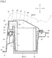
FIG. 2 is a cross-sectional view taken along the line A-A in FIG. 1.
FIG. 3 is a cross-sectional view taken along the line B-B in FIG. 2.
FIG. 4 is a front view of an air intake grille.
FIG. 5 is a cross-sectional view taken along the line C-C in FIG. 4.
DESCRIPTION OF EMBODIMENTS
Hereinafter, an embodiment of the invention will be described with reference to the drawings. The drawings shall be viewed in directions of the reference letters. In the following description, front-rear, left-right, and up-down correspond to directions seen from a driver, and in the drawing, the front of the vehicle is indicated by Fr, the rear is Rr, the left is L, the right is R, the upper is U, and the lower is D.
A vehicle V of the embodiment illustrated in FIGS. 1 and 2 is an electric vehicle in which a battery unit 20 which accommodates a battery is mounted below a rear seat 10.
Floor Structure
As illustrated in FIG. 1 and FIG. 2, in a floor panel 30 of the vehicle V, a front floor panel 31 which constitutes a floor portion of a passenger compartment 12 and a rear floor panel 32 which constitutes a floor portion of a cargo compartment and the like are connected below the rear seat 10. In the drawing, reference numerals 14 denote a carpet which covers the floor panel 30.
On the front side of the rear floor panel 32, an accommodation recess portion 16 is provided and the battery unit 20 is accommodated therein. On the front side and the rear side of the accommodation recess portion 16, a front reinforcing portion 17 and a rear reinforcing portion 18 which straddle the left and right skeleton members are provided and the battery unit 20 is accommodated in the accommodating recess portion 16 in a state where the battery unit 20 is sealed by an annular seal member 19.
A kick-up portion 33 which rises upward is formed at a rear end portion of the front floor panel 31. Further, a center tunnel 34 is formed along a front-rear direction at the center of the front floor panel 31 in a vehicle width direction.
An air intake grille 40 for taking in air in the passenger compartment is provided in the kick-up portion 33 located above the center tunnel 34 and below the center of the rear seat 10 so as to open forward. As illustrated in FIG. 3, the air intake grille 40 is attached to an intake duct 50 which guides air in the vehicle compartment to the battery unit 20 via the seal member 54.
Battery Unit
In the battery unit 20, a battery as an electric device D, a cooling mechanism for cooling the electric device D, and the like are accommodated in a case 21. The electric device D is not limited to a battery and may be a DC/DC converter, an inverter, or a combination thereof. The cooling mechanism includes a cooling fan which sucks air in the passenger compartment. The cooling fan may be disposed on the upstream side of the electric device D or may be disposed on the downstream side of the electric device D.
A case 21 is a resin member having a horizontally long, substantially rectangular parallelepiped shape with an upper opening and includes a box-shaped case main body 22 that opens upward and a lid member 23 that closes the opening of the case main body 22. The lid member 23 supports the seat front side (further front side than the buttocks) of the rear seat 10 on its upper surface.
A front wall portion 24 of the lid member 23 is provided with an intake port 25 into which an extension portion 51 of the intake duct 50 enters on the left side in the vehicle width direction.
Intake Duct
The intake duct 50 extends from the air intake grille 40 provided at the center of the vehicle V in the vehicle width direction to the left side in the vehicle width direction from the center in the vehicle width direction along the front wall portion 24 of the case body 22. The extension portion 51 extending rearward enters the intake port 25 provided in the front wall portion 24 of the lid member 23. That is, the air intake grille 40 is provided in one side (center in the vehicle width direction) of the intake duct 50 and the intake port 25 of the battery unit 20 is provided in the other side (left side in the vehicle width direction) of the intake duct 50. The air intake grille 40 and the intake port 25 are arranged offset in the vehicle width direction.
Further, a step 53 is provided in an intake passage 52 of the intake duct 50 upward from the air intake grille 40 toward the intake port 25. Accordingly, even when water droplets enter the inside of the intake duct 50 or when condensation occurs inside the intake duct 50, it is possible to prevent the water droplets and condensation from entering from the intake port 25. The intake passage 52 of the intake duct 50 may be inclined upward from the air intake grille 40 toward the intake port 25.
The air in the passenger compartment taken into the intake duct 50 from the air intake grille 40 flows along the front wall portion 24 of the lid member 23 from the center in the vehicle width direction to the left side in the vehicle width direction as indicated by arrows in FIGS. 2 and 3. The air in the passenger compartment is sent from the extension portion 51 which enters the inside of the case 21 from the intake port 25 toward the electric device D located at the lower side.
Air Intake Grille
Next, the air intake grille 40 will be described in detail with reference to FIGS. 3 to 5.
The air intake grille 40 includes a rectangular frame body 41 with two upper corners cut away, a plurality of first grille forming portions 42 and second grille forming portions 43 disposed in a lattice pattern inside the frame body 41, and a flow rate adjusting plate 44 disposed inside the frame body 41 so as to be perpendicular to the first grille forming portion 42 and the second grille forming portion 43. It is preferable that the frame body 41, the first grille forming portion 42, the second grille forming portion 43, and the flow rate adjusting plate 44 are integrally formed by injection molding or the like.
The first grille forming portion 42 is a plate-shaped body which is long in an up-down direction and has a predetermined width in the front-rear direction and the plurality of first grille forming portions 42 are provided at equal intervals along the vehicle width direction. The second grille forming portion 43 is a plate-shaped body which is long in the left-right direction and has a predetermined width in the front-rear direction and the plurality of second grille forming portions 43 are provided at equal intervals along the up-down direction. The first grille forming portion 42 and the second grille forming portion 43 are arranged in a lattice shape by being orthogonal to each other when viewed from the front-rear direction and a plurality of rectangular opening portions 45 are formed.
The flow rate adjusting plate 44 is a plate-shaped body extending in the left-right direction and the up-down direction. When the passenger compartment side is set as the front surface of the air intake grille 40, it is connected to the first grille forming portion 42 and the second grille forming portion 43 on the rear surface side of the air intake grille 40. Further, the flow rate adjusting plate 44 has flow rate adjusting windows 46 having a smaller opening area than the openings 45 in all the opening portions 45 or a part of the opening portions 45. In a part of the air intake grille 40, the opening area of the opening portions 45 and the opening area of the flow rate adjusting windows 46 may be the same. In FIG. 4, the flow rate adjusting window 46 is indicated by dots.
Further, as illustrated in FIG. 5, in the opening portion 45 provided with the flow rate adjusting windows 46, air in the passenger compartment taken into the air intake grille 40 flows from the opening portion 45 to the intake duct 50 via the flow rate adjusting windows 46. In this case, since the opening area of the flow rate adjusting windows 46 is smaller than the opening area of the opening portions 45, the flow velocity decreases on the passenger compartment side of the opening portion 45 and the flow velocity increases in the flow rate adjusting windows 46.
To explain using an equation, when the opening area on the passenger compartment side of the opening portion 45 is set to A1 and the wind speed of the air flowing through the passenger compartment side of the opening portion 45 is set to V1, and further the opening area of the flow rate adjusting windows 46 is set to A2, and still further the wind speed of the air flowing through the flow rate adjusting windows 46 is set to V2, A1·V1=A2·V2 is established because the air volume is the same between the passenger compartment side and the opposite side of the opening portion 45. The opening area A2 of the flow rate adjusting windows 46 is smaller than the opening area A1 of the opening portions 45, that is, V1<V2 is derived from A2<A1, and thus, the flow velocity V1 on the passenger compartment side of the opening portion 45 is smaller than the flow velocity V2 in the flow rate adjusting window 46. Therefore, the vibration properties around the air intake grille 40 are improved and discomfort to a passenger can be further reduced.
As described above, the air intake grille 40 and the intake port 25 are arranged offset in the vehicle width direction. Therefore, when the flow rate adjusting windows 46 are evenly arranged in the vehicle width direction of the air intake grille 40, the flow velocity of the air in the passenger compartment taken into the air intake grille 40 is fast on the intake port 25 side (in this embodiment, on the left side of the vehicle V, on the right side in FIG. 4) and the flow velocity decreases as it goes away from the intake port 25 in the vehicle width direction.
To eliminate such uneven flow velocity, in the embodiment, when the air intake grille 40 is divided into two areas P1 and P2 at the center O in the vehicle width direction, the sum of the opening areas of the flow rate adjusting windows 46 located in the area P1 on the opposite side to the intake port 25 is larger than the sum of the opening areas of the flow rate adjusting windows 46 located in the area P2 on the intake port 25 side.
Thus, by changing the opening area of the flow rate adjusting windows 46 according to the position of the intake port 25, the deviation of the flow velocity of the air in the passenger compartment taken into the air intake grille 40 can be adjusted in the vehicle width direction.
Furthermore, when the air intake grille 40 is divided into three areas Q1 to Q3 in the vehicle width direction, the sum of the opening areas of the flow rate adjusting windows 46 located in the central area Q2 is smaller than the sum of the opening areas of the flow rate adjusting windows 46 located in the area Q1 on the opposite side to the intake port 25 and is larger than the sum of the opening areas of the flow rate adjusting windows 46 located in the area Q3 on the intake port 25 side. In the example of FIG. 4, the opening area of the flow rate adjusting windows 46 is gradually reduced from the area Q1 toward the area Q3. Further, in the area Q3, the number of flow rate adjusting windows 46 is reduced as it goes toward the intake port 25 side.
By appropriately changing the sum of the opening areas of the flow rate adjusting windows 46 as described above, for example, the flow velocity of air taken in the center of the air intake grille 40 in the vehicle width direction can be made faster than the flow velocity of air taken in the left and right sides of the air intake grille 40 in the vehicle width direction. In other words, the flow velocity of air taken in the left and right sides of the air intake grille 40 in the vehicle width direction can be made slower than the flow velocity of air taken in the center of the air intake grille 40 in the vehicle width direction.
Generally, the rear seat 10 has a high usage frequency for the left and right rear seats 10 and a low usage frequency for the central rear seat 10. Thus, the flow velocity of the air taken into the air intake grille 40 on the left and right sides of the rear seat 10 which are used frequently is slower than that of the center of the rear seat 10 which is used less frequently. Therefore, the discomfort to a passenger sitting on the rear seat 10 can be further reduced.
SUMMARY
As described above, according to the embodiment, the flow rate adjusting plate 44 has the flow rate adjusting window 46 having the opening area smaller than the opening portion 45 inside the opening portion 45 formed by the first grille forming portion 42 and the second grille forming portion 43. Therefore, in the opening portion 45 on the passenger compartment side of the air intake grille 40, the flow velocity of the intake air can be reduced.
As a result, the vibration properties around the air intake grille 40 are improved and discomfort to a passenger can be reduced.
Further, the air intake grille 40 can prevent intrusion of foreign objects by the flow rate adjusting plate 44 together with the first grille forming portion 42 and the second grille forming portion 43.
The flow rate adjusting plate 44 is connected to the first grille forming portion 42 and the second grille forming portion 43 on the rear surface side of the air intake grille 40. Therefore, the flow rate adjusting plate 44 can be arranged to the rear side by the amount of the widths of the first grille forming portion 42 and the second grille forming portion 43 in the front-rear direction. As a result, the appearance design of the air intake grille can be improved.
Further, since the frame body 41, the first grille forming portion 42, the second grille forming portion 43, and the flow rate adjusting plate 44 are integrally formed, the manufacturing is easy and the handling property is excellent.
In addition, since the air intake grille 40 and the intake port 25 are offset in the vehicle width direction, it is possible to guide the air taken in from the air intake grille 40 to the intake port 25 while preventing foreign objects which have entered from the air intake grille 40 from entering the intake port 25.
When the air intake grille 40 and the intake port 25 are offset in the vehicle width direction, the air flow is fast in the region P2 on the intake port 25 side and the air flow is slow in the region P1 on the opposite side to the intake port 25. Therefore, by making the sum of the opening areas of the flow rate adjusting windows 46 located in the region P1 on the opposite side to the intake port 25 larger than the sum of the opening areas of the flow rate adjusting windows 46 located in the region P2 on the intake port 25 side, the flow velocity of air taken into the air intake grille 40 can be averaged in the vehicle width direction.
In addition, when the air intake grille 40 is disposed below the center of the rear seat 10, by making the sum of the opening areas of the flow rate adjusting windows 46 located in the central region Q2 smaller than the sum of the opening areas of the flow rate adjusting windows 46 located in the region Q1 on the opposite side to the intake port 25 and larger than the sum of the opening areas of the flow rate adjusting windows 46 located in the region Q3 on the intake port 25 side, the flow velocity of the air taken into the air intake grille 40 can be reduced at the left and right sides of the rear seat 10 which are frequently used with respect to the central side of the rear seat 10 which is not frequently used. Therefore, the discomfort to a passenger sitting on the rear seat 10 can be further reduced.
Moreover, since the air intake grille 40 is opened toward the front of the vehicle, it is possible to prevent foreign objects from entering from above when a passenger drops an object. The air intake grille 40 may be opened toward the rear of the vehicle.
Further, since the air intake grille 40 is disposed at the kick-up portion 33, that is, at the foot side of a passenger, it can reduce discomfort due to inhalation to the passenger compared to a case where the air intake grille 40 is disposed above the seat.
Further, the intake passage 52 of the intake duct 50 is provided with the step 53 upward from the air intake grille 40 toward the intake port 25. Therefore, even when water droplets enter the inside of the intake duct 50 or condensation occurs inside the intake duct 50, it is possible to prevent the water droplets and condensation water from entering through the intake port 25.
The invention is not limited to the embodiments and modifications described above. Modifications, improvements, and the likes can be made as appropriate.
For example, the number and shape of the opening portions 45 and the flow rate adjusting windows 46 can be arbitrarily set.
This application is based on a Japanese patent application (Japanese Patent Application No. 2017-132869) filed on Jul. 6, 2017, the contents of which are incorporated herein by reference.
REFERENCE SIGNS LIST
    • 10: rear seat
    • 21: case
    • 31: front floor panel
    • 33: kick-up portion
    • 40: air intake grille
    • 41: frame body
    • 42: first grille forming portion
    • 43: second grille forming portion
    • 44: flow rate adjusting plate
    • 45: opening portion
    • 46: flow rate adjusting window
    • 50: intake duct
    • 53: step
    • D: electric device
    • P1: region on opposite side to intake port
    • P2: region on intake port side
    • Q1: region on opposite side to intake port
    • Q2: central region
    • Q3: region on intake port side
    • V: vehicle

Claims (10)

The invention claimed is:
1. An air intake grille through which air in a passenger compartment of a vehicle passes, the air intake grille comprising:
a frame body;
a plurality of first grille forming portions;
a plurality of second grille forming portions; and
a flow rate adjusting plate disposed inside the frame body so as to be perpendicular to the first grille forming portions, wherein
the plurality of first grille forming portions and the plurality of second grille forming portions are arranged in a lattice shape inside the frame body,
the flow rate adjusting plate has a flow rate adjusting window inside an opening portion formed by the first grille forming portions and the second grille forming portions, and
the flow rate adjusting window has an opening area smaller than the opening portion.
2. The air intake grille according to claim 1, wherein
when a side of the passenger compartment is set as a front surface of the air intake grille, the flow rate adjusting plate is connected to the first grille forming portions and the second grille forming portions on a rear surface side of the air intake grille.
3. The air intake grille according to claim 1, wherein
the frame body, the plurality of first grille forming portions, the plurality of second grille forming portions, and the flow rate adjusting plate are integrally formed.
4. A vehicle comprising:
an air intake grille through which air in a passenger compartment of a vehicle passes;
an electric device;
a case for accommodating the electric device; and
an intake duct for connecting an intake port provided in the case and the air intake grille, wherein
the air intake grille includes a frame body, a plurality of first grille forming portions a plurality of second grille forming portions, and a flow rate adjusting plate disposed inside the frame body so as to be perpendicular to the first grille forming portions, wherein
the plurality of first grille forming portions and the plurality of second grille forming portions are arranged in a lattice shape inside the frame body,
the flow rate adjusting plate has a flow rate adjusting window inside an opening portion formed by the first grille forming portions and the second grille forming portions,
the flow rate adjusting window has an opening area smaller than the opening portion, and
the air intake grille and the intake port are arranged offset in a vehicle width direction.
5. The vehicle according to claim 4, wherein
when the air intake grille is divided into two regions at a center in the vehicle width direction,
a sum of opening areas of flow rate adjusting windows located in a region on an opposite side to the intake port is larger than a sum of opening areas of flow rate adjusting windows located in a region on the intake port side.
6. The vehicle according to claim 4, wherein
when the air intake grille is divided into three regions in the vehicle width direction,
a sum of opening areas of flow rate adjusting windows located in a central region is smaller than a sum of opening areas of flow rate adjusting windows located in a region on an opposite side to the intake port and is larger than the sum of the opening areas of the flow rate adjusting windows located in the region on the intake port side.
7. The vehicle according to claim 4, wherein
the air intake grille opens toward a front or rear of the vehicle.
8. The vehicle according to claim 4, wherein
the passenger compartment is provided with a rear seat behind a kick-up portion formed so as to rise from a front floor panel,
the electric device is disposed below the rear seat, and
the air intake grille is disposed in the kick-up portion.
9. The vehicle according to claim 8, wherein
the air intake grille is disposed in the kick-up portion in a center of the rear seat.
10. The vehicle according to claim 4, wherein
an intake passage of the intake duct is inclined upward from the air intake grille toward the intake port or has a step upward from the air intake grille toward the intake port.
US16/627,603 2017-07-06 2018-04-23 Air intake grille and vehicle Active 2038-06-29 US11192445B2 (en)

Applications Claiming Priority (4)

Application Number Priority Date Filing Date Title
JP2017132869 2017-07-06
JP2017-132869 2017-07-06
JPJP2017-132869 2017-07-06
PCT/JP2018/016482 WO2019008871A1 (en) 2017-07-06 2018-04-23 Air intake grille and vehicle

Publications (2)

Publication Number Publication Date
US20200122568A1 US20200122568A1 (en) 2020-04-23
US11192445B2 true US11192445B2 (en) 2021-12-07

Family

ID=64949916

Family Applications (1)

Application Number Title Priority Date Filing Date
US16/627,603 Active 2038-06-29 US11192445B2 (en) 2017-07-06 2018-04-23 Air intake grille and vehicle

Country Status (4)

Country Link
US (1) US11192445B2 (en)
JP (1) JP6713586B2 (en)
CN (1) CN110809525B (en)
WO (1) WO2019008871A1 (en)

Cited By (1)

* Cited by examiner, † Cited by third party
Publication number Priority date Publication date Assignee Title
USD971093S1 (en) * 2021-02-22 2022-11-29 Human Horizons (jiangsu) Technology Co., Ltd. Bumper

Families Citing this family (2)

* Cited by examiner, † Cited by third party
Publication number Priority date Publication date Assignee Title
JP2022083910A (en) 2020-11-25 2022-06-06 本田技研工業株式会社 Louver structure
USD1012804S1 (en) * 2021-10-12 2024-01-30 Bayerische Motoren Werke Aktiengesellschaft Front fender for a vehicle

Citations (21)

* Cited by examiner, † Cited by third party
Publication number Priority date Publication date Assignee Title
US3068891A (en) * 1959-07-27 1962-12-18 Blower Applic Company Flow regulator for air control
GB2381067A (en) 2001-08-31 2003-04-23 Honda Motor Co Ltd An air intake structure of a grille for a vehicle
US20060079166A1 (en) * 2002-03-15 2006-04-13 Trw Automotive Electronics & Components Gmbh & Co, Kg Air vent for ventilation systems
US7419209B1 (en) * 2007-05-30 2008-09-02 Lear Corporation Seat assembly providing airflow path to cool batteries
US20080296075A1 (en) * 2007-05-30 2008-12-04 Ford Global Technologies, Llc Ductless cooling system for a vehicle power storage unit
US20090183935A1 (en) * 2006-04-28 2009-07-23 Toyota Jodosha Kabushiki Kaisha Structure for mounting power supply apparatus on vehicle
US20100241308A1 (en) * 2006-03-28 2010-09-23 Yoshiaki Kikuchi Cooling system, motor vehicle equipped with cooling system, and control method of cooling system
US20100276220A1 (en) * 2007-12-25 2010-11-04 Honda Motor Co., Ltd. Battery cooling air intake structure
US20120247848A1 (en) * 2009-12-14 2012-10-04 Honda Motor Co., Ltd. Cooling structure for electricity storage device
US8311708B2 (en) * 2010-02-16 2012-11-13 Ford Global Technologies, Llc Adjustable grill shutter system
US8316974B2 (en) * 2008-12-22 2012-11-27 Veritas Ag Adjustable radiator grill arrangement
US20130000864A1 (en) * 2010-03-18 2013-01-03 Calsonic Kansei Corporation Heat element cooling device
US20130092348A1 (en) * 2011-10-13 2013-04-18 Suzuki Motor Corporation Vehicular battery cooling device
US8535126B2 (en) * 2008-02-15 2013-09-17 Roger W. Fincher Air flow control mechanism and methods
US20140262573A1 (en) * 2011-11-14 2014-09-18 Honda Motor Co., Ltd. Battery pack for electric vehicle
US20150253781A1 (en) * 2014-03-04 2015-09-10 Automatic Airflow Balancing Llc Airflow balancing valve for hvac systems
JP2015209115A (en) 2014-04-25 2015-11-24 本田技研工業株式会社 Cooling structure of electric device
JP2016084026A (en) 2014-10-27 2016-05-19 本田技研工業株式会社 vehicle
US20160301120A1 (en) 2015-04-08 2016-10-13 Honda Motor Co., Ltd. Cooling structure of battery and battery unit
JP2016199105A (en) 2015-04-08 2016-12-01 本田技研工業株式会社 Battery unit
US9623741B2 (en) * 2012-12-27 2017-04-18 Toyota Boshoku Kabushiki Kaisha Exhaust structure for vehicle

Family Cites Families (7)

* Cited by examiner, † Cited by third party
Publication number Priority date Publication date Assignee Title
JP2005255044A (en) * 2004-03-12 2005-09-22 Mitsubishi Fuso Truck & Bus Corp Structure of front grille of vehicle
WO2011099549A1 (en) * 2010-02-10 2011-08-18 本田技研工業株式会社 Cooling structure for vehicle battery unit
DE102013218217A1 (en) * 2013-09-11 2015-03-26 Mahle International Gmbh air filter
JP2015214211A (en) * 2014-05-09 2015-12-03 アイシン精機株式会社 Grille device for vehicle
JP6530932B2 (en) * 2015-03-18 2019-06-12 本田技研工業株式会社 vehicle
US9840144B2 (en) * 2015-08-19 2017-12-12 Mazda Motor Corporation Front air-rectifying structure of automotive vehicle
JP6657864B2 (en) * 2015-12-01 2020-03-04 三菱自動車工業株式会社 Grill mounting structure and vehicle equipped with this structure

Patent Citations (21)

* Cited by examiner, † Cited by third party
Publication number Priority date Publication date Assignee Title
US3068891A (en) * 1959-07-27 1962-12-18 Blower Applic Company Flow regulator for air control
GB2381067A (en) 2001-08-31 2003-04-23 Honda Motor Co Ltd An air intake structure of a grille for a vehicle
US20060079166A1 (en) * 2002-03-15 2006-04-13 Trw Automotive Electronics & Components Gmbh & Co, Kg Air vent for ventilation systems
US20100241308A1 (en) * 2006-03-28 2010-09-23 Yoshiaki Kikuchi Cooling system, motor vehicle equipped with cooling system, and control method of cooling system
US20090183935A1 (en) * 2006-04-28 2009-07-23 Toyota Jodosha Kabushiki Kaisha Structure for mounting power supply apparatus on vehicle
US7419209B1 (en) * 2007-05-30 2008-09-02 Lear Corporation Seat assembly providing airflow path to cool batteries
US20080296075A1 (en) * 2007-05-30 2008-12-04 Ford Global Technologies, Llc Ductless cooling system for a vehicle power storage unit
US20100276220A1 (en) * 2007-12-25 2010-11-04 Honda Motor Co., Ltd. Battery cooling air intake structure
US8535126B2 (en) * 2008-02-15 2013-09-17 Roger W. Fincher Air flow control mechanism and methods
US8316974B2 (en) * 2008-12-22 2012-11-27 Veritas Ag Adjustable radiator grill arrangement
US20120247848A1 (en) * 2009-12-14 2012-10-04 Honda Motor Co., Ltd. Cooling structure for electricity storage device
US8311708B2 (en) * 2010-02-16 2012-11-13 Ford Global Technologies, Llc Adjustable grill shutter system
US20130000864A1 (en) * 2010-03-18 2013-01-03 Calsonic Kansei Corporation Heat element cooling device
US20130092348A1 (en) * 2011-10-13 2013-04-18 Suzuki Motor Corporation Vehicular battery cooling device
US20140262573A1 (en) * 2011-11-14 2014-09-18 Honda Motor Co., Ltd. Battery pack for electric vehicle
US9623741B2 (en) * 2012-12-27 2017-04-18 Toyota Boshoku Kabushiki Kaisha Exhaust structure for vehicle
US20150253781A1 (en) * 2014-03-04 2015-09-10 Automatic Airflow Balancing Llc Airflow balancing valve for hvac systems
JP2015209115A (en) 2014-04-25 2015-11-24 本田技研工業株式会社 Cooling structure of electric device
JP2016084026A (en) 2014-10-27 2016-05-19 本田技研工業株式会社 vehicle
US20160301120A1 (en) 2015-04-08 2016-10-13 Honda Motor Co., Ltd. Cooling structure of battery and battery unit
JP2016199105A (en) 2015-04-08 2016-12-01 本田技研工業株式会社 Battery unit

Non-Patent Citations (3)

* Cited by examiner, † Cited by third party
Title
Jan. 18, 2021, Indian Office Action issued for related IN Application No. 202047000265.
Jun. 19, 2018, International Search Opinion issued for related PCT Application No. PCT/JP2018/016482.
Jun. 19, 2018, International Search Report issued for related PCT Application No. PCT/JP2018/016482.

Cited By (2)

* Cited by examiner, † Cited by third party
Publication number Priority date Publication date Assignee Title
USD971093S1 (en) * 2021-02-22 2022-11-29 Human Horizons (jiangsu) Technology Co., Ltd. Bumper
USD1008894S1 (en) 2021-02-22 2023-12-26 Human Horizons (jiangsu) Technology Co., Ltd. Bumper

Also Published As

Publication number Publication date
CN110809525A (en) 2020-02-18
JP6713586B2 (en) 2020-06-24
US20200122568A1 (en) 2020-04-23
JPWO2019008871A1 (en) 2020-05-21
WO2019008871A1 (en) 2019-01-10
CN110809525B (en) 2023-01-03

Similar Documents

Publication Publication Date Title
US11312205B2 (en) Vehicle
US10434897B2 (en) Vehicle high-voltage system equipment unit, vehicle battery unit and vehicle
US11192445B2 (en) Air intake grille and vehicle
KR101103166B1 (en) Cooling-air-intake structure of battery
AU2008327219B2 (en) Vehicular power supply system
US9490459B2 (en) Vehicular battery pack device
US10005336B2 (en) Vehicle
CN103855442B (en) Battery pack cooling structure for motor car
US20160144905A1 (en) Duct structure on vehicle side surface
JP6573680B2 (en) vehicle
JP6123226B2 (en) Cooling device for vehicle battery pack
CN112590489B (en) Air conditioner duct for vehicle
JP2019104321A (en) Cooling duct
JP6668906B2 (en) Battery cooling air discharge structure
JP2005007915A (en) Battery pack cooling structure, and floor board
CN111731154B (en) Vehicle with a steering wheel
CN213007606U (en) Vehicle body lower structure
CN217170449U (en) Cooling structure for power storage device
JP6155244B2 (en) vehicle
KR101394673B1 (en) Apparatus for prevention water from flowing into high voltage electric parts
JP2012121371A (en) Air-exhaust structure of air cooling battery unit
JP2019137331A (en) Cooling device

Legal Events

Date Code Title Description
AS Assignment

Owner name: HONDA MOTOR CO., LTD., JAPAN

Free format text: ASSIGNMENT OF ASSIGNORS INTEREST;ASSIGNOR:KANO, HIROSHI;REEL/FRAME:051447/0545

Effective date: 20191219

FEPP Fee payment procedure

Free format text: ENTITY STATUS SET TO UNDISCOUNTED (ORIGINAL EVENT CODE: BIG.); ENTITY STATUS OF PATENT OWNER: LARGE ENTITY

STPP Information on status: patent application and granting procedure in general

Free format text: DOCKETED NEW CASE - READY FOR EXAMINATION

STPP Information on status: patent application and granting procedure in general

Free format text: NON FINAL ACTION MAILED

STPP Information on status: patent application and granting procedure in general

Free format text: RESPONSE TO NON-FINAL OFFICE ACTION ENTERED AND FORWARDED TO EXAMINER

STPP Information on status: patent application and granting procedure in general

Free format text: NOTICE OF ALLOWANCE MAILED -- APPLICATION RECEIVED IN OFFICE OF PUBLICATIONS

STPP Information on status: patent application and granting procedure in general

Free format text: PUBLICATIONS -- ISSUE FEE PAYMENT VERIFIED

STCF Information on status: patent grant

Free format text: PATENTED CASE