US11172170B2 - Image recording apparatus, image recording method, and image recording program - Google Patents
Image recording apparatus, image recording method, and image recording program Download PDFInfo
- Publication number
- US11172170B2 US11172170B2 US16/373,485 US201916373485A US11172170B2 US 11172170 B2 US11172170 B2 US 11172170B2 US 201916373485 A US201916373485 A US 201916373485A US 11172170 B2 US11172170 B2 US 11172170B2
- Authority
- US
- United States
- Prior art keywords
- vehicle
- image
- event
- image data
- positional relation
- Prior art date
- Legal status (The legal status is an assumption and is not a legal conclusion. Google has not performed a legal analysis and makes no representation as to the accuracy of the status listed.)
- Active, expires
Links
Images


Classifications
-
- G—PHYSICS
- G06—COMPUTING OR CALCULATING; COUNTING
- G06V—IMAGE OR VIDEO RECOGNITION OR UNDERSTANDING
- G06V20/00—Scenes; Scene-specific elements
- G06V20/50—Context or environment of the image
- G06V20/56—Context or environment of the image exterior to a vehicle by using sensors mounted on the vehicle
- G06V20/58—Recognition of moving objects or obstacles, e.g. vehicles or pedestrians; Recognition of traffic objects, e.g. traffic signs, traffic lights or roads
-
- H—ELECTRICITY
- H04—ELECTRIC COMMUNICATION TECHNIQUE
- H04N—PICTORIAL COMMUNICATION, e.g. TELEVISION
- H04N7/00—Television systems
- H04N7/18—Closed-circuit television [CCTV] systems, i.e. systems in which the video signal is not broadcast
- H04N7/188—Capturing isolated or intermittent images triggered by the occurrence of a predetermined event, e.g. an object reaching a predetermined position
-
- G06K9/00805—
-
- G06K9/325—
-
- G—PHYSICS
- G06—COMPUTING OR CALCULATING; COUNTING
- G06T—IMAGE DATA PROCESSING OR GENERATION, IN GENERAL
- G06T7/00—Image analysis
- G06T7/70—Determining position or orientation of objects or cameras
-
- G—PHYSICS
- G06—COMPUTING OR CALCULATING; COUNTING
- G06V—IMAGE OR VIDEO RECOGNITION OR UNDERSTANDING
- G06V20/00—Scenes; Scene-specific elements
- G06V20/60—Type of objects
- G06V20/62—Text, e.g. of license plates, overlay texts or captions on TV images
-
- G—PHYSICS
- G07—CHECKING-DEVICES
- G07C—TIME OR ATTENDANCE REGISTERS; REGISTERING OR INDICATING THE WORKING OF MACHINES; GENERATING RANDOM NUMBERS; VOTING OR LOTTERY APPARATUS; ARRANGEMENTS, SYSTEMS OR APPARATUS FOR CHECKING NOT PROVIDED FOR ELSEWHERE
- G07C5/00—Registering or indicating the working of vehicles
- G07C5/08—Registering or indicating performance data other than driving, working, idle, or waiting time, with or without registering driving, working, idle or waiting time
- G07C5/0841—Registering performance data
- G07C5/085—Registering performance data using electronic data carriers
- G07C5/0866—Registering performance data using electronic data carriers the electronic data carrier being a digital video recorder in combination with video camera
-
- G—PHYSICS
- G08—SIGNALLING
- G08G—TRAFFIC CONTROL SYSTEMS
- G08G1/00—Traffic control systems for road vehicles
-
- G—PHYSICS
- G08—SIGNALLING
- G08G—TRAFFIC CONTROL SYSTEMS
- G08G1/00—Traffic control systems for road vehicles
- G08G1/20—Monitoring the location of vehicles belonging to a group, e.g. fleet of vehicles, countable or determined number of vehicles
- G08G1/205—Indicating the location of the monitored vehicles as destination, e.g. accidents, stolen, rental
-
- H—ELECTRICITY
- H04—ELECTRIC COMMUNICATION TECHNIQUE
- H04N—PICTORIAL COMMUNICATION, e.g. TELEVISION
- H04N23/00—Cameras or camera modules comprising electronic image sensors; Control thereof
- H04N23/60—Control of cameras or camera modules
-
- H—ELECTRICITY
- H04—ELECTRIC COMMUNICATION TECHNIQUE
- H04N—PICTORIAL COMMUNICATION, e.g. TELEVISION
- H04N23/00—Cameras or camera modules comprising electronic image sensors; Control thereof
- H04N23/60—Control of cameras or camera modules
- H04N23/61—Control of cameras or camera modules based on recognised objects
-
- H04N5/23218—
-
- H—ELECTRICITY
- H04—ELECTRIC COMMUNICATION TECHNIQUE
- H04N—PICTORIAL COMMUNICATION, e.g. TELEVISION
- H04N5/00—Details of television systems
- H04N5/76—Television signal recording
- H04N5/765—Interface circuits between an apparatus for recording and another apparatus
- H04N5/77—Interface circuits between an apparatus for recording and another apparatus between a recording apparatus and a television camera
-
- H—ELECTRICITY
- H04—ELECTRIC COMMUNICATION TECHNIQUE
- H04N—PICTORIAL COMMUNICATION, e.g. TELEVISION
- H04N5/00—Details of television systems
- H04N5/76—Television signal recording
- H04N5/91—Television signal processing therefor
-
- H—ELECTRICITY
- H04—ELECTRIC COMMUNICATION TECHNIQUE
- H04N—PICTORIAL COMMUNICATION, e.g. TELEVISION
- H04N7/00—Television systems
- H04N7/18—Closed-circuit television [CCTV] systems, i.e. systems in which the video signal is not broadcast
-
- G—PHYSICS
- G08—SIGNALLING
- G08B—SIGNALLING OR CALLING SYSTEMS; ORDER TELEGRAPHS; ALARM SYSTEMS
- G08B13/00—Burglar, theft or intruder alarms
- G08B13/18—Actuation by interference with heat, light, or radiation of shorter wavelength; Actuation by intruding sources of heat, light, or radiation of shorter wavelength
- G08B13/189—Actuation by interference with heat, light, or radiation of shorter wavelength; Actuation by intruding sources of heat, light, or radiation of shorter wavelength using passive radiation detection systems
- G08B13/194—Actuation by interference with heat, light, or radiation of shorter wavelength; Actuation by intruding sources of heat, light, or radiation of shorter wavelength using passive radiation detection systems using image scanning and comparing systems
- G08B13/196—Actuation by interference with heat, light, or radiation of shorter wavelength; Actuation by intruding sources of heat, light, or radiation of shorter wavelength using passive radiation detection systems using image scanning and comparing systems using television cameras
- G08B13/19665—Details related to the storage of video surveillance data
Definitions
- the present invention relates to an image recording apparatus, an image recording method, and an image recording program.
- Ordinary drive recorders move, when an event, such as an impact, is detected, image data for a predetermined time including the detection time of the event to memory areas where the data is not overwritten (for example, see Japanese Unexamined Patent Application Publication No. 2000-6854).
- a conventional drive recorder in which recording of overwriting-prohibition moving images is limited for a predetermined time including an event detection time has been insufficient from the viewpoint of recording the state of a target after the event occurrence.
- a target vehicle has already collided with a vehicle at the detection time, and only a part of the target vehicle usually appears in the image imaged at this time. The information obtained from the image is insufficient to identify the target vehicle.
- An image recording apparatus includes an image-data acquiring unit that sequentially acquires image data obtained by imaging a periphery of a vehicle, an event-signal acquiring unit that acquires an event signal indicating occurrence of a predetermined event to the vehicle, a condition detecting unit that detects, when the event-signal acquiring unit acquires the event signal, whether a positional relation of a target with the vehicle satisfies a predetermined condition, and a writing controller that writes, when the event-signal acquiring unit does not acquire the event signal, the image data in a memory in a ring buffer format, or writes, when the event-signal acquiring unit acquires the event signal, the image data including a period from when the event signal has been acquired until the condition detecting unit has detected that the condition is satisfied in the memory such that the image data is not overwritten.
- An image recording method in a second aspect of the present invention includes an image-data acquiring step of sequentially acquiring image data obtained by imaging a periphery of a vehicle, an event-signal acquiring step of acquiring an event signal indicating occurrence of a predetermined event to the vehicle, a condition detecting step of detecting, when the event signal is acquired in the event-signal acquiring step, whether a predetermined condition is satisfied by changing a positional relation of a target with the vehicle, and a writing controlling step of writing, when the event signal is not acquired in the event-signal acquiring step, the image data in a memory in a ring buffer format, or of writing, when the event signal is acquired in the event-signal acquiring step, the image data including a period from when the event signal has been acquired until the condition has been detected to be satisfied in the condition detecting step in the memory such that the image data is not overwritten.
- a non-transitory computer readable medium storing an image recording program causing a computer to execute: an image-data acquiring step of sequentially acquiring image data obtained by imaging a periphery of a vehicle, an event-signal acquiring step of acquiring an event signal indicating occurrence of a predetermined event to the vehicle, a condition detecting step of detecting, when the event signal is acquired in the event-signal acquiring step, whether a predetermined condition is satisfied by changing a positional relation of a target with the vehicle, and a writing controlling step of writing, when the event signal is not acquired in the event-signal acquiring step, the image data in a memory in a ring buffer format, or of writing, when the event signal is acquired in the event-signal acquiring step, the image data including a period from when the event signal has been acquired until the condition has been detected to be satisfied in the condition detecting step in the memory such that the image data is not overwritten.
- FIG. 1 is a schematic diagram shown that a drive recorder according to a first to third embodiments is installed in a vehicle.
- FIG. 2 is a block diagram showing a configuration of the drive recorder according to the first embodiment.
- FIG. 3A is a conceptual diagram for explaining a ring buffer set in a memory card according to the first embodiment.
- FIG. 3B is a conceptual diagram for explaining a ring buffer set in the memory card according to the first embodiment.
- FIG. 3C is a conceptual diagram for explaining a ring buffer set in the memory card according to the first embodiment.
- FIG. 4A is a schematic diagram showing a state immediately after an event occurs and a state in which another vehicle is separated according to the first embodiment.
- FIG. 4B is a schematic diagram showing a state immediately after the event occurs and a state in which the other vehicle is separated according to the first embodiment.
- FIG. 5 is a diagram for explaining overwriting-prohibition target files over time according to the first embodiment.
- FIG. 6 is a flowchart showing a control procedure of the drive recorder according to the first embodiment.
- FIG. 7A is a schematic diagram showing a state in which another vehicle is separated according to a second embodiment.
- FIG. 7B is a schematic diagram showing a state in which the other vehicle is separated according to the second embodiment.
- FIG. 8 is a flowchart showing a control procedure of a drive recorder according to the second embodiment.
- FIG. 9A is a schematic diagram showing a state immediately after an event occurs and a state in which another vehicle is separated according to a third embodiment.
- FIG. 9B is a schematic diagram showing a state immediately after the event occurs and a state in which the other vehicle is separated according to the third embodiment.
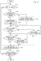
- FIG. 10 is a flowchart showing a control procedure of a drive recorder according to the third embodiment.
- FIG. 11 is a schematic diagram showing that another drive recorder is installed in a vehicle.
- FIG. 12 is a block diagram showing a configuration of a drive recorder according to a fourth embodiment.
- FIG. 13A is a conceptual diagram for explaining a ring buffer set in a memory card according to the fourth embodiment.
- FIG. 13B is a conceptual diagram for explaining a ring buffer set in the memory card according to the fourth embodiment.
- FIG. 13C is a conceptual diagram for explaining a ring buffer set in the memory card according to the fourth embodiment.
- FIG. 14A is a schematic diagram showing a state immediately after an event occurs and a state in which another vehicle is separated according to the fourth embodiment.
- FIG. 14B is a schematic diagram showing a state immediately after the event occurs and a state in which the other vehicle is separated according to the fourth embodiment.
- FIG. 15 is a diagram for explaining overwriting-prohibition target files over time according to the fourth embodiment.
- FIG. 16 is a flowchart showing a control procedure of the drive recorder according to the fourth embodiment.
- FIG. 17 is a block diagram showing a configuration of a drive recorder according to a fifth embodiment.
- FIG. 18A is schematic diagram showing a state in which another vehicle is separated according to the fifth embodiment.
- FIG. 18B is schematic diagram showing a state in which the other vehicle is separated according to the fifth embodiment.
- FIG. 19 is a flowchart showing a control procedure of the drive recorder according to the fifth embodiment.
- FIG. 20 is a block diagram showing a configuration of a drive recorder according to a sixth embodiment.
- FIG. 21A is a conceptual diagram for explaining a ring buffer set in a memory card according to the sixth embodiment.
- FIG. 21B is a conceptual diagram for explaining a ring buffer set in the memory card according to the sixth embodiment.
- FIG. 21C is a conceptual diagram for explaining a ring buffer set in the memory card according to the sixth embodiment.
- FIG. 22A is a schematic diagram showing a state immediately after an event occurs and a state in which another vehicle is separated according to the sixth embodiment.
- FIG. 22B is a schematic diagram showing a state immediately after the event occurs and a state in which the other vehicle is separated according to the sixth embodiment.
- FIG. 23 is a diagram for explaining overwriting-prohibition target files over time according to the sixth embodiment.
- FIG. 24 is a flowchart showing a control procedure of the drive recorder according to the sixth embodiment.
- FIG. 1 is a schematic diagram showing that a drive recorder 1100 , which is an example of an image recording apparatus according to a first to third embodiments, is installed in a vehicle 1900 .
- the drive recorder 1100 includes a camera unit 1110 .
- the camera unit 1110 is installed at the upper part of the windshield so as to face the travelling direction of the vehicle 1900 in order to image the front peripheral environment. Note that, the camera unit 1110 has, for example, a diagonal viewing angle of about 130° as indicated by the dashed dotted lines.
- the vehicle 1900 includes, at its front, a plurality of distance sensors 1170 that detects a distance to another vehicle, a pedestrian, or the like.
- the distance sensors 1170 are, for example, millimeter-wave radars or ultrasonic sensors and output distance signals as detection results to the drive recorder 1100 .
- the distance sensors 1170 may be incorporated in the drive recorder 1100 .
- the vehicle 1900 further includes an acceleration sensor 1160 that detects acceleration such as an impact received by the vehicle 1900 .
- the acceleration sensor 1160 outputs an acceleration signal as a detection result to the drive recorder 1100 .
- the acceleration sensor 1160 may be incorporated in the drive recorder 1100 .
- FIG. 2 is a block diagram showing a configuration of the drive recorder 1100 .
- the drive recorder 1100 mainly includes the camera unit 1110 and a main body unit 1130 .
- the camera unit 1110 mainly includes a lens 1112 , an image sensor 1114 , and an analog front end (AFE) 1116 .
- the lens 1112 guides incident subject luminous flux to the image sensor 1114 .
- the lens 1112 may be constituted by a plurality of optical-lens groups.
- the image sensor 1114 is, for example, a CMOS image sensor.
- the image sensor 1114 adjusts, according to an exposure time per frame designated by a system controller 1131 , a charge storage time with an electronic shutter and performs photoelectric conversion to output a pixel signal.
- the image sensor 1114 transfers the pixel signal to the AFE 1116 .
- the AFE 1116 adjusts, according to an amplification gain designated by the system controller 1131 , the level of the pixel signal and performs A/D conversion into digital data to output the data to the main body unit 1130 as pixel data.
- the camera unit 1110 may include a mechanical shutter and an iris diaphragm. When the camera unit 1110 includes a mechanical shutter and an iris diaphragm, the system controller 1131 uses them to adjust the amount of light incident on the image sensor 1114 .
- the main body unit 1130 mainly includes the system controller 1131 , an image input IF 1132 , an work memory 1133 , a system memory 1134 , an image processing unit 1135 , a display outputting unit 1136 , a memory controller 1137 , a memory IF 1138 , an input/output IF 1139 , a position detecting unit 1140 , and a bus line 1141 .
- the image input IF 1132 functions as an image-data acquiring unit that sequentially acquires image data obtained by the camera unit 1110 performing imaging, receives the pixel data from the camera unit 1110 connected with the main body unit 1130 , and transfers the pixel data to the bus line 1141 .
- the work memory 1133 is, for example, a volatile high-speed memory.
- the work memory 1133 receives the pixel data from the AFE 1116 via the image input IF 1132 and collectively records it as image data for one frame.
- the work memory 1133 transfers the image data in frame units to the image processing unit 1135 .
- the work memory 1133 is appropriately used as a temporary storage area by the image processing unit 1135 during image processing.
- the image processing unit 1135 performs various kinds of image processing to the received image data to generate image data conforming to a predetermined format. In the case of generating, for example, moving image data in an MPEG file format, the image processing unit 1135 performs white balance processing, gamma processing, and the like to the image data in each frame and, then, performs compression processing of the image data in each frame and of the image data in the adjacent frames. The image processing unit 1135 sequentially generates display image data from the generated image data and transfers the display image data to the display outputting unit 1136 .
- image data in each frame constituting moving image data is referred to as frame image data
- an image expressed by frame image data is referred to a frame image.
- the display outputting unit 1136 converts the display image data received from the image processing unit 1135 into image signals displayable on a display unit 1180 and outputs the image signals.
- the display unit 1180 may be, for example, a display panel of a car navigation system or a dedicated display panel provided integrally with the drive recorder 1100 .
- the display unit 1180 is capable of sequentially displaying the image signals received from the display outputting unit 1136 .
- the system memory 1134 is, for example, a non-volatile recording medium such as an SSD.
- the system memory 1134 records and stores constants, variables, setting values, control programs, and the like necessary for the drive recorder 1100 to operate.
- the memory IF 1138 is a connection interface for loading a detachable memory card 1150 .
- the memory card 1150 is a non-volatile memory, and a flash memory is used, for example.
- the memory controller 1137 performs memory control for writing the image data in the memory card 1150 loaded in the memory IF 1138 . That is, the memory controller 1137 functions as a writing controller that writes image data in the memory card 1150 . Specific memory control is to be described later.
- the input/output IF 1139 is an external-apparatus connection interface that receives a signal from an external apparatus and transfers the signal to the system controller 1131 and that receives a control signal, such as a signal request to an external apparatus, from the system controller 1131 and transmits the control signal to the external apparatus.
- the above acceleration signal from the acceleration sensor 1160 and the above distance signals from the distance sensors 1170 are input to the system controller 1131 via the input/output IF 1139 .
- the input/output IF 1139 functions as an acceleration-signal acquiring unit in cooperation with the system controller 1131 when receiving an acceleration signal, and functions as a distance-signal acquiring unit in cooperation with the system controller 1131 when receiving a distance signal.
- the system controller 1131 determines that an event, such as a collision, has occurred.
- the system controller 1131 also functions as an event-signal acquiring unit.
- the system controller 1131 further determines that an approaching object has approached the vehicle 1900 from a history of the frame images received from the image processing unit 1135 . Thus, the system controller 1131 also functions as an approaching-object detecting unit.
- the position detecting unit 1140 receives the frame image data, to which the image processing unit 1135 has performed predetermined pre-processing, and detects whether a target subject has a predetermined positional relation in the frame image. When detecting that the target subject satisfies the predetermined positional relation in a frame image, the position detecting unit 1140 detects that the positional relation of the target subject with the vehicle 1900 satisfies a predetermined condition. Thus, the position detecting unit 1140 functions as a condition detecting unit that detects whether a positional relation of a target with the vehicle 1900 satisfies a predetermined condition.
- the position detecting unit 1140 When recognizing that the target subject has the predetermined positional relation in the frame image, the position detecting unit 1140 outputs time information about when the frame image has been imaged to the system controller 1131 .
- the system controller 1131 is, for example, a CPU and directly or indirectly controls the constituent elements of the drive recorder 1100 .
- the control by the system controller 1131 is implemented by a control program or the like read from the system memory 1134 .
- FIGS. 3A, 3B, and 3C are conceptual diagrams for explaining a ring buffer set in the memory card 1150 .
- the drive recorder 1100 processes images sequentially imaged by the camera unit 1110 with the image processing unit 1135 to generate a moving image file for every minute. Then, the memory controller 1137 successively records the moving image files generated by the image processing unit 1135 in the memory card 1150 via the memory IF 1138 .
- the storage capacity of the memory card 1150 has the limit, and the number of moving image files to be recorded is limited. Since the drive recorder 1100 continues generating moving image files while the vehicle 1900 keeps traveling, it is impossible to record the most-newly generated moving image file in the memory card 1150 after a certain time passes. Thus, the memory controller 1137 continues recording processing in a ring buffer format in which the newest moving image file is written in the storage area storing the oldest moving image file when the storage capacity of the memory card 1150 reaches the limit.
- FIG. 3A is a conceptual diagram showing that all memory areas 1151 of the memory card 1150 are used as a ring buffer 1152 .
- memory areas each capable of storing one moving image file are represented by X 1 , X 2 , . . . , Xn
- the memory controller 1137 successively records the first moving image file in X 1 and the next moving image file in X 2 . Then, after the n-th moving image file is recorded in Xn, the first moving image file recorded in X 1 is overwritten with the n+1-th moving image file. Similarly, the moving image file recorded in X 2 is overwritten with the n+2-th moving image file.
- By recording moving image files in the ring buffer format it is possible to store the newest moving image files for the capacity of the ring buffer 1152 .
- FIG. 3B is a conceptual diagram for explaining writing control in a conventional drive recorder.
- the conventional drive recorder recognizes event occurrence when receiving a large acceleration signal caused by, for example, a collision with another vehicle, and copies the moving image file recording the event occurrence time in an area in which overwriting is prohibited.
- the memory Xn is changed to a non-volatile buffer 1153 , and the moving image file is copied in the non-volatile buffer 1153 as an event recording file.
- the non-volatile buffer 1153 is the area excluded from the storage area where files are recorded in the ring buffer format, in other words, the area in which overwriting is prohibited. If an event occurs a plurality of times, the memory areas Xn ⁇ 1, Xn ⁇ 2, and the like are successively changed to the non-volatile buffer 1153 every time an event occurs. That is, the ring buffer 1152 is reduced, as the non-volatile buffer 1153 is added.
- the memory area of the non-volatile buffer 1153 is used as the ring buffer 1152 again when the memory card 1150 is formatted or when a target moving image file is erased by an instruction of a user. Note that, the capacity used as the non-volatile buffer 1153 may be preset.
- moving image data including a period from an event occurrence time until the position detecting unit 1140 has detected that the positional relation of a target vehicle with the vehicle 1900 satisfies a predetermined condition is written in a memory so that the moving image data is not overwritten in the present embodiment.
- moving image data including a period from an event occurrence time until a target subject satisfies a predetermined positional relation in continuously imaged images is copied in the non-volatile buffer 1153 .
- the predetermined positional relation in the present embodiment indicates a relation in which another vehicle, which is the target subject, appears with a road surface interposing between the vehicle and the target subject in the image frame.
- a relation in which a change in the direction of a target is detected, a relation in which a target is detected to be smaller than a predetermined size, or the like may be set as a predetermined positional relation.
- FIG. 3C is a conceptual diagram for explaining writing control in the drive recorder 1100 according to the present embodiment.
- the methods for adding the non-volatile buffer 1153 , for moving target moving image data, for recording in the ring buffer 1152 , and the like are similar to those of the example in FIG. 3B , but a moving image file to be copied in the non-volatile buffer 1153 is different in the present embodiment.
- a moving image file recorded in the memory area X 4 of the ring buffer 1152 includes an event occurrence time in its imaging period similarly to the example in FIG. 3B .
- the camera unit 1110 continues imaging after the event, and the generated moving image files are successively written in X 5 , X 6 , and the like.
- the position detecting unit 1140 continuously acquires the frame image data constituting these moving image files and detects, in the frame image, whether the target subject satisfies the predetermined positional relation (position detection).
- position detection the frame image in which the position detection has occurred for the first time after the event occurrence is included in the moving image file recorded in the memory area X 6 .
- the time indicated by the time information of the frame image in which the position detection has occurred for the first time after the event occurrence is referred to as a position detection time.
- the memory controller 1137 copies three moving image files of the moving image file in X 4 including the event occurrence time, the moving image file in X 5 , and the moving image file in X 6 including the position detection time in the non-volatile buffer 1153 as event recording files. That is, the memory areas from Xn ⁇ 2 to Xn are changed to the non-volatile buffer 1153 , and the target moving image files are copied in the non-volatile buffer 1153 . If different moving image files are recorded in the non-volatile buffer 1153 , the non-volatile buffer 1153 is added so as to avoid the memory areas recording the moving image files.
- the image data is expected to include the entire image of the target subject or the state after the accident.
- the present embodiment exemplifies, as an example of the predetermined positional relation in an event of a collision between vehicles, a relation in which a road surface is detected between a vehicle and the other vehicle.
- FIG. 4A shows the state immediately after another vehicle 1910 has collided with the vehicle 1900 (immediately after event occurrence), and
- FIG. 4B shows that the other vehicle 1910 is separated from the vehicle 1900 thereafter and that a road surface 1920 is detected between the vehicle 1900 and the other vehicle 1910 .
- the system controller 1131 recognizes that an event has occurred by receiving an acceleration signal greater than a threshold caused by the collision.
- the image imaged at this time has the range enclosed by the outside frame of FIG. 4A . That is, the other vehicle 1910 is too close to the vehicle 1900 that the lower part thereof does not appear. Only with this image, the entire image of the other vehicle 1910 close to the vehicle 1900 at the accident time cannot be detected. Thus, it is impossible to attain an object of identifying the other vehicle 1910 .
- the image processing unit 1135 may generate a moving image file with the information, such as the model and color of the other vehicle 1910 , embedded in the frame images or add the information to the header of the moving image file.
- FIG. 5 is a diagram for explaining overwriting-prohibition target files over time according to the present embodiment. The drawing indicates the passage of time from the left to the right.
- the moving image files including these three periods are set as overwriting-prohibition target files which are event recording files. That is, these moving image files are copied in the non-volatile buffer 1153 .
- the approaching other vehicle 1910 can appear in the moving image files in the prior period, which is used to specify the cause of the accident, to confirm that the other vehicle appearing in the moving image files in the main period is the accident cause, and the like.
- an approaching rescuer and the escaping other vehicle 1910 can appear in the moving image files in the posterior period, which is used to identify the persons who are involved in the accident, to pursue the criminal liability, and the like.
- FIG. 6 is a flowchart showing a control procedure of the drive recorder 1100 .
- the procedure is started from when a traveling start preparation for the vehicle 1900 is completed.
- the completion of the traveling start preparation for the vehicle 1900 means, for example, starting the engine of the vehicle 1900 , turning the power on, or the like.
- the drive recorder 1100 may operate at all times regardless of the state of the vehicle.
- the camera unit 1110 starts imaging as the procedure is started, and the image processing unit 1135 sequentially generates moving image files.
- the memory controller 1137 successively records the moving image files in the memory card 1150 in the ring buffer format.
- the system controller 1131 monitors acceleration signals received from the acceleration sensor 1160 . The following processing is performed during the control for recording the normal traveling.
- the system controller 1131 determines, in step S 1101 , whether an acceleration signal greater than a threshold has been received from the acceleration sensor 1160 , that is, whether an event has occurred. When determining that the acceleration signal greater than the threshold has been received, the system controller 1131 determines that an event has occurred and proceeds to step S 1102 . When determining that the acceleration signal greater than the threshold has not been received, the system controller 1131 proceeds to step S 1108 .
- the system controller 1131 determines, in step S 1102 , whether a history of the frame images received from the image processing unit 1135 has captured the approach of a target. When, for example, another vehicle has been detected in a frame image before the event detection and the image of the other vehicle has become gradually larger and been the largest at the moment of the event detection, the system controller 1131 determines that the other vehicle has approached the vehicle 1900 . In this manner, when determining that a series of frame images has captured the approach of the target, the system controller 1131 proceeds to step S 1104 or to step S 1103 otherwise.
- the system controller 1131 causes, in step S 1103 , the position detecting unit 1140 to detect other vehicles in the entire area of each frame image in the moving image data generated after the event occurrence. Specifically, the position detecting unit 1140 stores, for example, the shape pattern of the external appearance of the vehicle to detect other vehicles by image matching. The system controller 1131 extracts the other vehicles detected by the position detecting unit 1140 as target subjects. Note that, the system controller 1131 may set all the other vehicles appearing in the frame images as target subjects or only the other vehicle closest to the vehicle 1900 as a target subject by measuring the distances to other vehicles with the distance sensors 1170 . On the other hand, the system controller 1131 extracts, in step S 1104 , the other vehicle determined in step S 1102 as a target subject.
- the system controller 1131 checks, in step S 1105 , the target subject extracted in step S 1103 or S 1104 and determines whether the target subject has been detected to have a predetermined first positional relation in the frame image.
- the predetermined first positional relation is, for example, a relation in which the position detecting unit 1140 can recognize the road surface 1920 between the other vehicle 1910 and the vehicle 1900 in the frame image.
- the position detecting unit 1140 detects, between the other vehicle 1910 and the vehicle 1900 , a pixel area in which the movement vector through the adjacent frame images is zero, for example. By detecting such a pixel area, it is possible to recognize the road surface 1920 between the other vehicle 1910 and the vehicle 1900 .
- step S 1106 when determining that the target subject has the predetermined first positional relation, the system controller 1131 proceeds to step S 1107 .
- the system controller 1131 determines, in step S 1106 , the main period and the accompanied prior period or the prior period and the posterior period as described with reference to FIG. 5 .
- the memory controller 1137 copies the moving image files corresponding to these periods in the non-volatile buffer 1153 which is an overwriting-prohibition area. That is, the system controller 1131 copies, as the processing in step S 1106 , the moving image files including the prior period and the main period in the non-volatile buffer 1153 which is an overwriting-prohibition area.
- the system controller 1131 copies, as the processing in step S 1106 , the moving image files including the prior period, the main period, and the posterior period in the non-volatile buffer 1153 which is an overwriting-prohibition area.
- the system controller 1131 determines, in step S 1108 , whether a video-recording stop signal has been received.
- the video-recording stop signal is generated, for example, as the vehicle 1900 stops traveling or by a user operating a stop button.
- the system controller 1131 causes the camera unit 1110 to stop imaging, stops recording the generated moving image files in the ring buffer format, and terminates a series of processing.
- the system controller 1131 returns to step S 1101 to continue a series of processing.
- the system controller 1131 copies the moving image files until a predetermined period has passed from the event occurrence in the non-volatile buffer 1153 , which is an overwriting-prohibition area, and proceeds to step S 1106 .
- the system controller 1131 copies the moving image files until that point of time in the non-volatile buffer 1153 , which are overwriting-prohibition areas, as event recording files.
- step S 1105 when determining that the target subject does not have the predetermined first positional relation in step S 1105 , the system controller 1131 proceeds to step S 1107 to determine whether a predetermined time has passed from the event occurrence. When determining that the predetermined time has not passed, the system controller 1131 returns to step S 1105 to continue determining whether the target subject has been detected to have the predetermined first positional relation in the frame image. When determining that the predetermined time has passed, the system controller 1131 proceeds to step S 1106 .
- the system controller 1131 may copy the moving image files in the non-volatile buffer 1153 so that overwriting of the moving image files is prohibited until the storage capacity of the memory card 1150 reaches its limit.
- the system controller 1131 may copy the moving image file corresponding to the section, in which the image has changed, in the non-volatile buffer 1153 which is an overwriting-prohibition area.
- the system controller 1131 analyses whether the image has changed in the newest moving image file while continuing recording the generated moving image files. Specifically, the analysis is performed by comparing adjacent frame images to determine whether the images are matched. Then, when the images are matched in adjacent frames in all the frames, the system controller 1131 determines that the image has not changed in the moving image file. When only a part of a frame image is not matched, the system controller 1131 determines that the image has changed. Note that, when a part of an image area which is narrow relative to a frame image is changed, the system controller 1131 may determine that the image has not changed as a whole.
- the system controller 1131 When determining that the image has not changed in the newest moving image file, the system controller 1131 causes the memory controller 1137 to erase, from the memory card 1150 , the image file corresponding to the section in which the image has not changed. On the other hand, when determining that the image has changed, the system controller 1131 causes the memory controller 1137 to determine whether the ring buffer 1152 of the memory card 1150 has been exhausted, that is, whether the memory areas, of the ring buffer 1152 , recording the moving image files generated before the event occurrence have been used up. When the memory controller 1137 determines that the memory areas have been used up, the system controller 1131 determines that there is no memory area for recording new moving image files and terminates a series of processing.
- the memory controller 1137 may change all the memory areas 1151 of the memory card 1150 to the non-volatile buffer 1153 .
- the system controller 1131 returns to step S 1102 to continue determining whether the target subject has the predetermined first positional relation by following the target subject in the frame images generated sequentially.
- step S 1103 or S 1104 it has been described that another vehicle has been successfully detected and extracted as a target subject in step S 1103 or S 1104 in the present embodiment. However, if a target subject is not extracted, the detection of another vehicle may be repeatedly performed until, for example, the ring buffer 1152 is exhausted. Alternatively, the system controller 1131 may proceed directly to step S 1105 , determine, when a target subject is not detected, that no target subject satisfies the predetermined first positional relation, and proceed to step S 1108 .
- the relation in which the road surface 1920 can be recognized between the other vehicle 1910 and the vehicle 1900 in the frame image in step S 1105 is defined as the predetermined first positional relation in the present embodiment.
- another positional relation may be defined as the predetermined first positional relation.
- a relation in which the outline of the other vehicle 1910 is in the frame image, that is, the entire image of the other vehicle 1910 can be grasped or a relation in which the image of the other vehicle 1910 is matched with a shape pattern stored in advance may be defined as the predetermined first positional relation.
- the position detecting unit 1140 detects, in step S 1105 , the outline of the other vehicle 1910 which becomes small as the other vehicle 1910 is separated, for example. By detecting that all the points consisting the outline of the other vehicle 1910 radially converge, it is possible to determine that the entire image of the other vehicle 1910 is in the frame image.
- a time when a target subject detected to have a predetermined first positional relation in an acquired frame image is set as an end time and that a period until a predetermined time passes from the end time is set as a posterior period.
- a positional relation in which, for example, the road surface 1920 can be recognized between the other vehicle 1910 and the vehicle 1900 is defined as a predetermined first positional relation.
- the present embodiment exemplifies that a period from when a target subject is detected to have a predetermined first positional relation in a frame image until the target subject is detected to have a predetermined second positional relation is set as a posterior period.
- a positional relation in which the position detecting unit 1140 detects that the other vehicle 1910 has changed its direction or a positional relation in which the image of the other vehicle 1910 becomes too small is defined as the predetermined second positional relation.
- a configuration of a drive recorder which is an example of an image recording apparatus according to the second embodiment, is similar to the configuration of the drive recorder 1100 according to the first embodiment.
- a time for example, when the other vehicle 1910 is detected to have changed its direction as shown in FIG. 7A or when the image of the other vehicle 1910 becomes too small as shown in FIG. 7B is set as an end point of a posterior period.
- the other vehicle 1910 After the other vehicle 1910 has the positional relation shown in FIG. 7A or 7B , it is expected that the other vehicle 1910 is out of the frame image or that only an unclear image is obtained.
- the posterior period is terminated.
- the position detecting unit 1140 detects, for example, whether a side-face part 1911 of the other vehicle 1910 can be recognized as shown in FIG. 7A .
- the position detecting unit 1140 stores, for example, shape patterns of various vehicle models when viewed from different angles and color patterns and determines whether the image of the other vehicle 1910 is similar to the side-face part of another vehicle stored in advance.
- the position detecting unit 1140 determines that the other vehicle 1910 has changed its direction and outputs time information about when the frame image has been imaged to the system controller 1131 .
- the position detecting unit 1140 may detect, for example, whether the image of the other vehicle 1910 has become smaller than a predetermined size as shown in FIG. 7B .
- the position detecting unit 1140 follows, for example, the size of a detection frame 1811 which is the detection area of the other vehicle 1910 .
- the position detecting unit 1140 outputs information about time when the frame image is imaged to the system controller 1131 .
- FIG. 8 is a flowchart showing a control procedure according to the present embodiment.
- step S 1206 is added instead of step S 1106 in the flowchart in FIG. 6 .
- steps S 1205 and S 1207 are added.
- the same step number is assigned to the processing common to the that in the flowchart in FIG. 6 , and the description thereof is appropriately omitted.
- step S 1105 When determining, in step S 1105 , that a target subject has been detected to have a predetermined first positional relation in the frame image, the system controller 1131 proceeds to step S 1205 .
- the target subject mentioned here is, for example, the other vehicle 1910 .
- the predetermined first positional relation is, for example, a relation in which the position detecting unit 1140 can detect the road surface 1920 between the other vehicle 1910 and the vehicle 1900 in the frame image.
- the system controller 1131 determines, in step S 1205 , whether the other vehicle 1910 has a predetermined second positional relation in the frame image.
- the predetermined second positional relation may be, for example, a relation in which the position detecting unit 1140 can detect that the other vehicle 1910 has changed its direction or a relation in which the position detecting unit 1140 can detect that the image of the other vehicle 1910 becomes smaller than a predetermined size.
- the system controller 1131 proceeds to step S 1206 .
- the system controller 1131 proceeds to step S 1207 .
- the system controller 1131 determines, in step S 1206 , the main period and the prior period as described in the first embodiment and further determines a posterior period in which an end time is set at the time when the other vehicle 1910 has been detected to have the predetermined second positional relation in the frame image.
- the memory controller 1137 copies the moving image files corresponding to these three periods in the non-volatile buffer 1153 which is an overwriting-prohibition area.
- the system controller 1131 copies, in step S 1207 , the moving image files until a predetermined period has passed after the target subject has been determined to satisfy the predetermined first positional relation or until a predetermined period has passed after the predetermined period has passed in step S 1107 in the non-volatile buffer 1153 which is an overwriting-prohibition area, and proceeds to step S 1206 .
- the system controller 1131 copies, as an event recording file, the moving image files until that point of time in the non-volatile buffer 1153 which is an overwriting-prohibition area.
- step S 1205 when determining that the target subject does not have the predetermined second positional relation in step S 1205 , the system controller 1131 proceeds to step S 1207 to determine whether a predetermined time has passed from the event occurrence. When determining that the predetermined time has not passed, the system controller 1131 returns to step S 1205 to continue determining whether the target subject has been detected to have the predetermined second positional relation in the frame image. When determines that the predetermined time has passed, the system controller 1131 proceeds to step S 1206 .
- the system controller 1131 may copy the moving image files in the non-volatile buffer 1153 so that overwriting of the moving image files is prohibited until the storage capacity of the memory card 1150 reaches its limit.
- the system controller 1131 may copy the moving image file corresponding to the section, in which the image has changed, in the non-volatile buffer 1153 which is an overwriting-prohibition area.
- the system controller 1131 analyses whether the image has changed in the newest moving image file while continuing recording the generated moving image files. Specifically, the analysis is performed by comparing adjacent frame images to determine whether the images are matched. Then, when the images are matched in adjacent frames in all the frames, the system controller 1131 determines that the image has not changed in the moving image file. When only a part of a frame image is not matched, the system controller 1131 determines that the image has changed. Note that, when a part of an image area which is narrow relative to a frame image is changed, the system controller 1131 may determine that the image has not changed as a whole.
- the system controller 1131 When determining that the image has not changed in the newest moving image file, the system controller 1131 causes the memory controller 1137 to erase, from the memory card 1150 , the image file corresponding to the section in which the image has not changed. On the other hand, when determining that the image has changed, the system controller 1131 causes the memory controller 1137 to determine whether the ring buffer 1152 of the memory card 1150 has been exhausted, that is, whether the memory areas, of the ring buffer 1152 , recording the moving image files generated before the event occurrence have been used up. When the memory controller 1137 determines that the memory areas have been used up, the system controller 1131 determines that there is no memory area for recording new moving image files and terminates a series of processing.
- the memory controller 1137 may change all the memory areas 1151 of the memory card 1150 to the non-volatile buffer 1153 .
- the system controller 1131 returns to step S 1205 to continue determining whether the other vehicle 1910 has the predetermined second positional relation in the frame images generated sequentially.
- the relation in which the road surface 1920 can be recognized between the other vehicle 1910 and the vehicle 1900 in the frame image in step S 1105 is defined as the predetermined first positional relation in the present embodiment.
- another positional relation may be defined as the predetermined first positional relation.
- a relation in which the outline of the other vehicle 1910 is in the frame image, that is, the entire image of the other vehicle 1910 can be grasped or a relation in which the image of the other vehicle 1910 is matched with a shape pattern stored in advance may be defined as the predetermined first positional relation.
- the relation in which the other vehicle 1910 is detected to have changed its direction in the frame image in step S 1205 or the relation in which the image of the other vehicle 1910 is detected to become smaller than a predetermined size is defined as the predetermined second positional relation in the present embodiment.
- another positional relation may be defined as the predetermined second positional relation.
- a relation in which the other vehicle 1910 is out of the frame image or a relation in which an emergency vehicle, such as a patrol car, can be detected near the other vehicle 1910 may be defined as the predetermined second positional relation.
- a target subject is another vehicle.
- a third embodiment exemplifies that a target subject is a person.
- a configuration of a drive recorder which is an example of an image recording apparatus according to the third embodiment, is similar to the configuration of the drive recorder 1100 according to the first embodiment.
- FIG. 9A shows a state immediately after the vehicle 1900 collides with a pedestrian 1930
- FIG. 9B shows a state in which the pedestrian 1930 is detected to get up thereafter.
- the system controller 1131 recognizes that an event has occurred by receiving an acceleration signal greater than a threshold caused by the collision.
- the image imaged immediately after the collision has the range enclosed by the outside frame of FIG. 9A .
- a pedestrian having collided with a vehicle normally falls or crouches near the vehicle.
- the system controller 1131 recognizes the pedestrian 1930 as a target subject, and the position detecting unit 1140 determines whether the pedestrian 1930 has been detected to have a predetermined positional relation in the frame image.
- the position detecting unit 1140 may determine, for example, whether the pedestrian 1930 has gotten up as shown in FIG. 9B or whether the whole body of the pedestrian 1930 has been detected. Alternatively, the position detecting unit 1140 may determine whether the pedestrian 1930 has been out of the frame image or whether, the image of the pedestrian 1930 has become smaller than a predetermined size.
- FIG. 10 is a flowchart showing a control procedure according to the present embodiment.
- steps S 1302 , S 1303 , S 1304 , and S 1305 are added instead of steps S 1102 , S 1103 , S 1104 , and S 1105 in the flowchart in FIG. 6 .
- the same step number is assigned to the processing common to that in the flowchart in FIG. 6 , and the description thereof is appropriately omitted.
- the system controller 1131 determines, in step S 1302 , whether a history of the frame images received from the image processing unit 1135 has captured the approach of a person. When, for example, a pedestrian has become gradually larger and been the largest at the moment of the event detection, the system controller 1131 determines that the pedestrian has approached the vehicle 1900 . In this manner, when determining that a series of frame images has captured the approach of the person, the system controller 1131 proceeds to step S 1304 or to step S 1303 otherwise.
- the system controller 1131 causes, in step S 1303 , the position detecting unit 1140 to detect a person in the entire area of each frame image in the moving image data generated after the event occurrence. Specifically, the position detecting unit 1140 stores, for example, shape patterns of person appearances to detect a person by image matching. The system controller 1131 extracts the person detected by the position detecting unit 1140 as a target subject. Note that, the system controller 1131 may set all the persons appearing in the frame images as target subjects or only the person closest to the vehicle 1900 as a target subject by measuring the distances to persons with the distance sensors 1170 . On the other hand, the system controller 1131 extracts, in step S 1304 , the person determined in step S 1302 as a target subject.
- the system controller 1131 checks, in step S 1305 , the target subject extracted in step S 1303 or S 1304 and determines whether the target subject has been detected to have a predetermined third positional relation in the frame image.
- the predetermined third positional relation is, for example, a relation in which the position detecting unit 1140 can detect that the pedestrian 1930 has gotten up.
- the position detecting unit 1140 detects, for example, a plurality of points indicating a part of the pedestrian 1930 , such as the head, the body, or the legs, and determines whether the pedestrian 1930 is lying, standing, or the like according to the positional relation of the points.
- the system controller 1131 proceeds to step S 1106 .
- the system controller 1131 proceeds to step S 1107 .
- the following processing is similar to that of the control procedure in the first embodiment.
- step S 1303 or S 1304 it has been described that a person has been successfully detected and extracted as a target subject in step S 1303 or S 1304 in the present embodiment. However, if a target subject is not extracted, the detection of a person may be repeatedly performed until, for example, the ring buffer 1152 is exhausted. Alternatively, the system controller 1131 may proceed directly to step S 1305 , determine, when a target subject is not detected, that no target subject satisfies the predetermined third positional relation, and proceed to step S 1108 .
- the relation in which the position detecting unit 1140 can detect that the pedestrian 1930 has gotten up in the frame image in step S 1305 is defined as the predetermined third positional relation in the present embodiment.
- another positional relation may be defined as the predetermined third positional relation.
- a relation in which the outline of the pedestrian 1930 is in the frame image, that is, the entire image of the pedestrian 1930 can be grasped or a relation in which the image of the pedestrian 1930 is detected to become smaller than a predetermined size may be defined as the predetermined third positional relation.
- FIG. 11 is a schematic diagram showing that another drive recorder 1100 ′ is installed in a vehicle 1900 ′.
- the vehicle 1900 ′ differs from the above the vehicle 1900 in that a plurality of distance sensors 1170 ′ is provided at the rear.
- the drive recorder 1100 ′ differs from the above drive recorder 1100 in that a camera unit 1110 ′ that images the rear peripheral environment is provided in addition to the camera unit 1110 . With the vehicle 1900 ′ and the drive recorder 1100 ′ configured in this manner, it is possible to handle a target colliding from a rear side.
- the memory IF 1138 by configuring the memory IF 1138 so as to load two memory cards 1150 , it is possible to use one memory card 1150 for the front side, and the other memory card 1150 for the rear side. Naturally, the memory areas of one memory card 1150 may be divided and used for the front side and the rear side.
- the system controller 1131 determines the direction in which the target has collided with the vehicle 1900 ′ with the acceleration signal.
- the system controller 1131 performs the above writing control to be performed after event occurrence to the image data acquired from the camera unit 1110 .
- the system controller 1131 performs the above writing control to be performed after event occurrence to the image data acquired from the camera unit 1110 ′.
- the system controller 1131 extracts direction information related to the occurrence direction in which the event has occurred to the vehicle 1900 ′ from the acceleration signal and determines, based on the direction information, whether image data to be subjected to the position detection is the image data from the camera unit 1110 or the image data from the camera unit 1110 ′. Then, the system controller 1131 acquires the determined image data and performs the above writing control. With the vehicle 1900 ′ and the drive recorder 1100 ′ configured in this manner, it is possible to more precisely record information about the target vehicle related to the event.
- the system controller 1131 may extract both another vehicle and a person appearing in the frame images as target subjects and set a period until each of them satisfies a predetermined positional relation as a main period.
- the system controller 1131 may extract, for example, targets other than an automobile or a person, such as an animal and a two-wheeled vehicle, that causes an event as target subjects.
- the memory areas 1151 are divided into the continuous ring buffer 1152 and the continuous non-volatile buffer 1153 in the above embodiments.
- the ring buffer 1152 and the non-volatile buffer 1153 may not be physically continuous.
- a part of the ring buffer 1152 is changed to the non-volatile buffer 1153 and a target moving image file is copied in the changed non-volatile buffer 1153 in the above embodiments.
- the writing control for prohibiting overwriting is not limited to this. For example, by setting a flag for prohibiting overwriting in a memory area recording a target moving image file, the area may be treated as the non-volatile buffer 1153 . In this case, it is possible to omit the processing for copying the moving image file.
- the memory areas 1151 of one memory card 1150 are divided into the ring buffer 1152 and the non-volatile buffer 1153 in the above embodiments.
- both the memory card 1150 used as the ring buffer 1152 and the memory card 1150 used as the non-volatile buffer 1153 may be loaded.
- a memory mounted in the main body unit 1130 may be used instead of the detachable memory card 1150 .
- the above writing control may be performed to a memory which is not physically adjacent.
- a moving image file for example, for one minute is set as a unit for writing control in the above embodiments.
- the unit for writing control is not limited to one moving image file.
- writing control may be performed in frame units.
- target image data is not limited to moving image data and may be, for example, still image data obtained by interval photographing.
- the acceleration sensor 1160 is used as a sensor that detects event occurrence in the above embodiments.
- another sensor may be used.
- a strain sensor that detects deformation caused by a collision of a target or a temperature sensor that detects an abnormal temperature may be used.
- a plurality of sensors may be used in combination.
- sensors, such as the acceleration sensor 1160 may be incorporated in the drive recorder. Strain signals, temperature signals, and the like, which are outputs from these sensors, are used as event signals for detecting an event similarly to an acceleration signal.
- the acceleration sensor 1160 outputs an acceleration signal to the system controller 1131 and the system controller 1131 determines whether the acceleration signal is greater than a threshold in the above embodiments.
- the method in which the system controller 1131 detects an event is not limited to this.
- the acceleration sensor 1160 may output only an acceleration signal greater than the threshold to the system controller 1131 . In this case, it is possible to set a time when the system controller 1131 has received the acceleration signal as an event detection time.
- the above other sensors may be used in a similar manner.
- the history of the frame images received from the image processing unit 1135 is used in order to acquire information before event detection in the above embodiments.
- the method for acquiring information before event detection is not limited to this.
- an approach of a target may be detected with a history of distance signals from the distance sensors 1170 .
- the multiple distance sensors 1170 are provided at the front of the vehicle 1900 , any one of the distance sensors 1170 can detect an approach of a target.
- the branched processing for intensively searching an area in a certain direction may be omitted depending on the capability or the like of the position detecting unit 1140 . In the case of omitting the branched processing, steps S 1102 and S 1104 in FIG. 6 are omitted, for example.
- the distance sensors 1170 are installed at the vehicle 1900 and the system controller 1131 acquires distance signals from the distance sensors 1170 in the above embodiments.
- the system controller 1131 acquires distance signals from the distance sensors 1170 in the above embodiments.
- a distance to a target may be calculated from a compound-eye image.
- the connection with the distance sensors 1170 can be omitted, and which makes the apparatus have a simpler configuration.
- the vehicle collides head-on with another vehicle as shown in FIGS. 4A, 4B, 7A, and 7B in the first and second embodiments.
- the configuration of the present invention is applicable when, for example, the vehicle 1900 collides with the other vehicle 1910 from a rear side.
- an end of a posterior period is set at a time when a fixed time T 2 has passed in the first and the third embodiments and an end of a posterior period is set at a time when a target subject satisfies a predetermined positional relation in a frame image in the second embodiment.
- these conditions may be combined.
- either longer period of a period until the fixed time T 2 has passed after the position detection or a period until the target subject satisfies the predetermined positional relation in the frame image may be set as a posterior period.
- the image file recorded so as not to be overwritten is usable in inspections or the like of the accident.
- a drive recorder 2100 according to a fourth and a fifth embodiments is described. Note that, in the description of the fourth and fifth embodiments, reference signs in 2000 s having the last three digits in common are newly assigned to elements which are the same as or directly corresponding to those in the first to third embodiments, and the description thereof is appropriately omitted.
- the drive recorder 2100 which is an example of an image recording apparatus according to the fourth and fifth embodiments, is installed and used in a vehicle 2900 corresponding to the vehicle 1900 similarly to the drive recorder 1100 according to the first to third embodiments (see FIG. 1 ).
- FIG. 12 is a block diagram showing a configuration of the drive recorder 2100 .
- the drive recorder 2100 mainly includes a camera unit 2110 and a main body unit 2130 .
- the camera unit 2110 mainly includes a lens 2112 , an image sensor 2114 , and an analogue front end (AFE) 2116 .
- the camera unit 2110 has the same constituent elements as those of the camera unit 1110 in the first to third embodiments.
- the main body unit 2130 mainly includes a system controller 2131 , an image input IF 2132 , a work memory 2133 , a system memory 2134 , an image processing unit 2135 , a display outputting unit 2136 , a memory controller 2137 , a memory IF 2138 , an input/output IF 2139 , a bus line 2141 , and a number-plate (NP) detecting unit 2142 .
- the main body unit 2130 has the same constituent elements as those of the main body unit 1130 according to the first to third embodiments, except that the number-plate detecting unit 2142 is included instead of the constituent element corresponding to the position detecting unit 1140 (see FIG. 2 ).
- the system controller 2131 detects, based on distance signals input from distance sensors 2170 via the input/output IF 2139 , a target, such as another vehicle or a person, approaching within a distance less than a predetermined threshold from the vehicle 2900 .
- a target such as another vehicle or a person
- the system controller 2131 also functions as a target detecting unit.
- the number-plate detecting unit 2142 receives frame image data subjected to predetermined pre-processing by the image processing unit 2135 and detects whether there is a number plate in the frame image. When detecting a number plate from a frame image, the number-plate detecting unit 2142 detects that a positional relation of another vehicle with the vehicle 2900 satisfies a predetermined condition. Thus, the number-plate detecting unit 2142 functions as a condition detecting unit that detects whether a positional relation of a target with the vehicle 2900 satisfies a predetermined condition.
- the frame image data received by the number-plate detecting unit 2142 includes time information about when the frame image has been imaged.
- the number-plate detecting unit 2142 stores, for example, shapes, numbers, and characters specific to number plates and information about arrangements and colors thereof to detect a number plate by matching the frame image with the stored information. Note that, when a certain detecting area is designated in the entire area of the frame image, the number-plate detecting unit 2142 detects whether there is a number plate in the designated area. When detecting a number plate, the number-plate detecting unit 2142 outputs time information about when the frame image is imaged to the system controller 2131 . Note that, the number-plate detecting unit 2142 may further output the information about the numbers, characters, colors, and the like detected by matching to the system controller 2131 .
- FIGS. 13A, 13B, and 13C are conceptual diagrams for explaining a ring buffer set in a memory card 2150 .
- FIG. 13A is a conceptual diagram showing that all memory areas 2151 of the memory card 2150 are used as a ring buffer 2152 .
- Detailed control by the memory controller 2137 in this case is similar to the control by the memory controller 1137 in FIG. 3A , and the description thereof is omitted.
- FIG. 13B is a conceptual diagram for explaining writing control in a conventional drive recorder. Detailed control by the memory controller 2137 in this case is similar to the control by the memory controller 1137 in FIG. 3B , and the description thereof is omitted.
- moving image data including a period from an event occurrence time until the number-plate detecting unit 2142 detects that the positional relation of a target vehicle with the vehicle 2900 satisfies a predetermined condition is written in a memory so that the moving image data is not overwritten in the present embodiment.
- moving image data including a period from an event occurrence time until a number plate has been detected in continuously imaged images is copied in a non-volatile buffer 2153 .
- FIG. 13C is a conceptual diagram for explaining writing control in the drive recorder 2100 according to the present embodiment.
- the methods for adding the non-volatile buffer 2153 , for moving target moving image data, for recording in the ring buffer 2152 , and the like are similar to those of the example in FIG. 13B , but a moving image file to be copied in the non-volatile buffer 2153 is different in the present embodiment.
- a moving image file recorded in a memory area X 4 of the ring buffer 2152 includes an event occurrence time in its imaging period similarly to the example in FIG. 13B .
- the camera unit 2110 continues imaging after the event, and the generated moving image files are successively written in X 5 , X 6 , and the like.
- the number-plate detecting unit 2142 continuously acquires the frame image data constituting these moving image files and detects, in the frame image, whether there is a number plate (number-plate detection).
- the frame image in which the number-plate detection has occurred for the first time after the event occurrence is included in the moving image file recorded in a memory area X 6 .
- the time indicated by the time information of the frame image in which the number-plate detection has occurred for the first time after the event occurrence is referred to as a number-plate detection time.
- the memory controller 2137 copies three moving image files of the moving image file in X 4 including the event occurrence time, the moving image file in X 5 , and the moving image file in X 6 including the number-plate detection time in the non-volatile buffer 2153 as event recording files. That is, the memory areas from Xn ⁇ 2 to Xn are changed to the non-volatile buffer 2153 , and the target moving image files are copied in the non-volatile buffer 2153 . If different moving image files are recorded in the non-volatile buffer 2153 , the non-volatile buffer 2153 is added so as to avoid the memory areas recording the moving image files.
- FIG. 14A shows the state immediately after another vehicle 2910 has collided with the vehicle 2900 (immediately after event occurrence), and FIG. 14B shows that the other vehicle 2910 is separated from the vehicle 2900 thereafter and that a number plate 2912 is detected.
- the system controller 2131 recognizes that an event has occurred by receiving an acceleration signal greater than a threshold caused by the collision.
- the image imaged at this time has the range enclosed by the outside frame of FIG. 14A . That is, the other vehicle 2910 is too close to the vehicle 2900 that the lower part thereof does not appear. Only with this image, the number plate 2912 of the other vehicle 2910 close to the vehicle 2900 at the accident time cannot be detected. Thus, it is impossible to attain an object of identifying the other vehicle 2910 .
- the image processing unit 2135 may generate a moving image file with information about the numbers, characters, and colors of the number plate 2912 and information about the name of the automobile inspection registration office, the application of the vehicle, and the like discriminated therefrom embedded in the frame images or add the information in the header of the moving image file.
- FIG. 15 is a diagram for explaining overwriting-prohibition target files over time according to the present embodiment. The drawing indicates the passage of time from the left to the right.
- the moving image files including these three periods are set as overwriting-prohibition target files which are event recording files. That is, the moving image files are copied in the non-volatile buffer 2153 .
- the approaching other vehicle 2910 can appear in the moving image files in the prior period, which is used to specify the cause of the accident, to confirm that the other vehicle appearing in the moving image files in the main period is the accident cause, and the like.
- an approaching rescuer and the escaping the other vehicle 2910 can appear in the moving image files in the posterior period, which is used to identify the persons who are involved in the accident, to pursue the criminal liability, and the like.
- FIG. 16 is a flowchart showing a control procedure of the drive recorder 2100 .
- the procedure is started from when a traveling start preparation for the vehicle 2900 is completed.
- the completion of the traveling start preparation for the vehicle 2900 means, for example, starting the engine of the vehicle 2900 , turning the power on, or the like.
- the drive recorder 2100 may operate at all times regardless of the state of the vehicle.
- the camera unit 2110 starts imaging as the procedure is started, and the image processing unit 2135 sequentially generates moving image files.
- the memory controller 2137 successively records the moving image files in the memory card 2150 in the ring buffer format.
- the system controller 2131 monitors acceleration signals received from the acceleration sensor 2160 . The following processing is performed during the control for recording the normal traveling.
- the system controller 2131 determines, in step S 2101 , whether an acceleration signal greater than a threshold has been received from the acceleration sensor 2160 , that is, whether an event has occurred. When determining that the acceleration signal greater than the threshold has been received, the system controller 2131 determines that an event has occurred and proceeds to step S 2102 . When determining that the acceleration signal greater than the threshold has not been received, the system controller 2131 proceeds to step S 2108 .
- the system controller 2131 checks, in step S 2102 , a history of the distance signals received from the distance sensors 2170 .
- the multiple distance sensors 2170 are provided at the front of the vehicle 2900 , and any one of the distance sensors 2170 can detect an approach of a target vehicle.
- the system controller 2131 proceeds to step S 2104 or to step S 2103 otherwise.
- the system controller 2131 causes, in step S 2103 , the number-plate detecting unit 2142 to search for a number plate in the entire area of each frame image in the moving image data generated after the event occurrence.
- the system controller 2131 causes, in step S 2104 , the number-plate detecting unit 2142 to intensively search an area of each frame image in the moving image data generated after the event occurrence in the direction of an approaching object detected by the distance sensor 2170 before the event occurrence. For example, when the distance sensor 2170 that has detected the approaching object is installed to detect the distance in the right-side 1 ⁇ 4 field of an image, the number-plate detecting unit 2142 determines the right-side 1 ⁇ 4 of the image as a searching area. By limiting an area subjected to the number-plate detection, it is possible to perform number-plate detection processing at high speed, and it is expected that the other vehicle having the detected number plate is deeply connecting with the event.
- the system controller 2131 determines, in step S 2105 , whether a number plate has been detected from the frame images. When determining that a number plate has been detected, the system controller 2131 proceeds to step S 2106 . When determining that no number plate has been detected, the system controller 2131 proceeds to step S 2107 .
- the system controller 2131 determines, in step S 2106 , the main period and the accompanied prior period or the prior period and the posterior period as described with reference to FIG. 15 .
- the memory controller 2137 copies the moving image files corresponding to these periods in the non-volatile buffer 2153 which is an overwriting-prohibition area. That is, the system controller 2131 copies, as the processing in step S 2106 , the moving image files including the prior period and the main period in the non-volatile buffer 2153 which is an overwriting-prohibition area.
- the system controller 2131 copies, as the processing in step S 2106 , the moving image files including the prior period, the main period, and the posterior period in the non-volatile buffer 2153 which is an overwriting-prohibition area.
- the system controller 2131 determines, in step S 2108 , whether a video-recording stop signal has been received.
- the video-recording stop signal is generated, for example, as the vehicle 2900 stops traveling or by a user operating a stop button.
- the system controller 2131 causes the camera unit 2110 to stop imaging, stops recording the generated moving image files in the ring buffer format, and terminates a series of processing.
- the system controller 2131 returns to step S 2101 to constitute a series of processing.
- step S 2105 when no number plate has been detected in step S 2105 , the system controller 2131 copies the moving image files until a predetermined period has passed from the event occurrence in the non-volatile buffer 2153 , which is an overwriting-prohibition area, and proceeds to step S 2106 .
- the system controller 2131 copies the moving image files until that point of time in the non-volatile buffer 2153 , which is an overwriting-prohibition area, as event recording files.
- step S 2107 determine whether a predetermined time has passed from the event occurrence.
- the system controller 2131 returns to step S 2102 to continue detecting a number plate from the frame images.
- step S 2106 when determining that the predetermined time has passed, the system controller 2131 proceeds to step S 2106 .
- the system controller 2131 may copy the moving image files in the non-volatile buffer 2153 so that overwriting of the moving image files is prohibited until the storage capacity of the memory card 2150 reaches its limit.
- the system controller 2131 may copy the moving image file corresponding to the section, in which the image has changed, in the non-volatile buffer 2153 which is an overwriting-prohibition area.
- the system controller 2131 analyses whether the image has changed in the newest moving image file while continuing recording the generated moving image files. Specifically, the analysis is performed by comparing adjacent frame images to determine whether the images are matched. Then, when the images are matched in adjacent frames in all the frames, the system controller 2131 determines that the image has not changed in the moving image file. When only a part of a frame image is not matched, the system controller 2131 determines that the image has changed. Note that, when a part of an image area which is narrow relative to a frame image is changed, the system controller 2131 may determine that the image has not changed as a whole.
- the system controller 2131 When determining that the image has not changed in the newest moving image file, the system controller 2131 causes the memory controller 2137 to erase, from the memory card 2150 , the image file corresponding to the section in which the image has not changed. On the other hand, when determining that the image has changed, the system controller 2131 causes the memory controller 2137 to determine whether the ring buffer 2152 of the memory card 2150 has been exhausted, that is, whether the memory areas, of the ring buffer 2152 , recording the moving image files generated before the event occurrence have been used up. When the memory controller 2137 determines that the memory areas have been used up, the system controller 2131 determines that there is no memory area for recording new moving image files and terminates a series of processing.
- the memory controller 2137 may change all the memory areas 2151 of the memory card 2150 to the non-volatile buffer 2153 .
- the system controller 2131 returns to step S 2102 to continue searching for a number plate in the frame images generated sequentially.
- a period until a predetermined time has passed from an end time is set as a posterior period in the fourth embodiment of the present invention.
- the fifth embodiment exemplifies that a posterior period is determined based on a relative positional relation of a target vehicle in a frame image.
- FIG. 17 is a block diagram showing a configuration of a drive recorder 2200 which is an example of an image recording apparatus according to a fifth embodiment.
- the drive recorder 2200 further includes a position detecting unit 2140 in the main body unit 2130 included in the drive recorder 2100 according to the fourth embodiment.
- the other configuration is similar to that of the drive recorder 2100 . For this reason, the same reference signs are assigned to common functions or processing, and the description thereof is appropriately omitted.
- the position detecting unit 2140 receives the frame image data, to which the image processing unit 2135 has performed predetermined pre-processing, and detects whether the other vehicle 2910 has a predetermined positional relation in the frame image.
- the position detecting unit 2140 detects, for example, whether a road surface 2920 can be recognized between the other vehicle 2910 and the vehicle 2900 in the frame image as shown in FIG. 18A .
- the position detecting unit 2140 detects, between the number plate 2912 detected by the number-plate detecting unit 2142 and the vehicle 2900 , a pixel area in which the movement vector through the adjacent frame images is zero, for example. By detecting such a pixel area, it is possible to recognize the road surface 2920 between the other vehicle 2910 and the vehicle 2900 .
- the position detecting unit 2140 outputs time information about when the frame image has been imaged to the system controller 2131 .
- the position detecting unit 2140 may detect, for example, whether a side-face part 2911 of the other vehicle 2910 can be recognized as shown in FIG. 18B .
- the position detecting unit 2140 stores, for example, shape patterns of various vehicle models when viewed from different angles and color patterns, specifies the image of the other vehicle 2910 having the number plate 2912 detected by the number-plate detecting unit 2142 by matching, and follows the image in the frame images.
- the position detecting unit 2140 outputs time information about when the frame image has been imaged to the system controller 2131 . At this time, the position detecting unit 2140 may further output information about the model of the other vehicle detected by matching to the system controller 2131 .
- a period from when the number-plate detecting unit 2142 has detected the number plate 2912 until the position detecting unit 2140 has outputted the time information to the system controller 2131 is set as a posterior period, and the moving image files including three periods of the prior period, the main period, and the posterior period are copied in the non-volatile buffer 2153 as event recording files.
- the target vehicle has a predetermined positional relation with the vehicle as the posterior period, it is expected to widen the usage range of the images. That is, the other vehicle 2910 is recognized as a wider range image, and it is expected to further record, for example, the model of the other vehicle 2910 and its features, such as deformation or scratches.
- the image processing unit 2135 may generate a moving image file with the information, such as the model and color of the other vehicle 2910 , embedded in the frame images or add the information to the header of the moving image file.
- FIG. 19 is a flowchart showing a control procedure of the drive recorder 2200 .
- step S 2106 in the flowchart in FIG. 16 is omitted, and steps S 2205 , S 2206 , and S 2207 are added instead.
- steps S 2205 , S 2206 , and S 2207 are added instead.
- the same reference sign is assigned to the processing common to that in the flowchart in FIG. 16 , and the description thereof is appropriately omitted.
- step S 2205 When determining that a number plate has been detected from the frame image in step S 2105 , the system controller 2131 proceeds to step S 2205 . When determining that no number plate has been detected from the frame image in step S 2105 , the system controller 2131 proceeds to step S 2107 .
- the system controller 2131 determines, in step S 2205 , whether the other vehicle 2910 has a predetermined positional relation in the frame image. When determining that the other vehicle 2910 has the predetermined positional relation, the system controller 2131 proceeds to step S 2206 . When determining that the other vehicle 2910 does not have the predetermined positional relation, the system controller 2131 proceeds step S 2207 .
- the system controller 2131 determines, in step S 2207 , whether a predetermined time has passed from the event occurrence. When determining that the predetermined time has not passed, the system controller 2131 returns to step S 2205 to continue determining whether the other vehicle 2910 has the predetermined positional relation in the frame image. When determining that the predetermined time has passed, the system controller 2131 proceeds to step S 2206 .
- the system controller 2131 determines, in step S 2206 , the main period and the prior period as described in the fourth embodiment and further determines a posterior period in which an end time is set at the time when the other vehicle 2910 has been detected to have the predetermined positional relation in the frame image.
- the memory controller 2137 copies the moving image files corresponding to these three periods in the non-volatile buffer 2153 which is an overwriting-prohibition area.
- the system controller 2131 copies the moving image files until a predetermined period has passed from the number-plate detection in the non-volatile buffer 2153 , which is an overwriting-prohibition area, and proceeds to step S 2206 .
- the system controller 2131 copies the moving image files until three minutes has passed from the number-plate detection in the non-volatile buffer 2153 , which is an overwriting-prohibition area, as event recording files.
- step S 2205 when determining that the target subject does not have the predetermined positional relation in step S 2205 , the system controller 2131 proceeds to step S 2207 and determines whether a predetermined time has passed from the event occurrence. When determining that the predetermined time has not passed, the system controller 2131 returns to step S 2205 to continue determining whether the target subject has been detected to have the predetermined positional relation in the frame image. When determining that the predetermined time has passed, the system controller 2131 proceeds to step S 2206 .
- the system controller 2131 may copy the moving image files in the non-volatile buffer 2153 so that overwriting of the moving image files is prohibited until the storage capacity of the memory card 2150 reaches its limit.
- the system controller 2131 may copy the moving image file corresponding to the section, in which the image has changed, in the non-volatile buffer 2153 which is an overwriting-prohibition area.
- the system controller 2131 analyses whether the image has changed in the newest moving image file while continuing recording the generated moving image files. Specifically, the analysis is performed by comparing adjacent frame images to determine whether the images are matched. Then, when the images are matched in adjacent frames in all the frames, the system controller 2131 determines that the image has not changed in the moving image file. When only a part of a frame image is not matched, the system controller 2131 determines that the image has changed. Note that, when a part of an image area which is narrow relative to a frame image is changed, the system controller 2131 may determine that the image has not changed as a whole.
- the system controller 2131 When determining that the image has not changed in the newest moving image file, the system controller 2131 causes the memory controller 2137 to erase, from the memory card 2150 , the image file corresponding to the section in which the image has not changed. On the other hand, when determining that the image has changed, the system controller 2131 causes the memory controller 2137 to determine whether the ring buffer 2152 of the memory card 2150 has been exhausted, that is, whether the memory areas, of the ring buffer 2152 , recording the moving image files generated before the event occurrence have been used up. When the memory controller 2137 determines that the memory areas have been used up, the system controller 2131 determines that there is no memory area for recording new moving image files and terminates a series of processing.
- the memory controller 2137 may change all the memory areas 2151 of the memory card 2150 to the non-volatile buffer 2153 .
- the system controller 2131 returns to step S 2102 to continue determining whether the other vehicle 2910 has a predetermined positional relation in the frame images generated sequentially.
- the fourth and fifth embodiments have been described above. Furthermore, an example in which a slight modification is made is described below. Similarly to the modified example in the first to third embodiments, another camera unit and distance sensor can be installed at the rear of the vehicle (see FIG. 11 ). With the vehicle and the drive recorder configured in this manner, it is possible to handle a target colliding from a rear side.
- the memory IF 2138 by configuring the memory IF 2138 so as to load two memory cards 2150 , it is possible to use one memory card 2150 for the front side, and the other memory card 2150 for the rear side. Naturally, the memory areas of one memory card 2150 may be divided and used for the front side and the rear side.
- the system controller 2131 determines the direction in which the target has collided with the vehicle with the acceleration signal.
- the system controller 2131 performs the above writing control to be performed after event occurrence to the image data acquired from the camera unit 2110 .
- the system controller 2131 performs the above writing control to be performed after event occurrence to the image data acquired from a camera unit provided at the rear of the vehicle.
- the system controller 2131 extracts direction information related to the occurrence direction in which the event has occurred to the vehicle from the acceleration signal and determines, based on the direction information, whether the image data to be subjected to the number-plate detection is the image data from the camera unit 2110 or the image data from the camera unit provided at the rear of the vehicle. Then, the system controller 2131 acquires the determined image data and performs the above writing control. With the vehicle and the drive recorder configured in this manner, it is possible to more precisely record information about the target vehicle related to the event.
- the memory areas 2151 are divided into the continuous ring buffer 2152 and the continuous non-volatile buffer 2153 in the above fourth and fifth embodiments.
- the ring buffer 2152 and the non-volatile buffer 2153 may not be physically continuous.
- a part of the ring buffer 2152 is changed to the non-volatile buffer 2153 and a target moving image file is copied in the changed non-volatile buffer 2153 in the above embodiments.
- the writing control for prohibiting overwriting is not limited to this. For example, by setting a flag for prohibiting overwriting in a memory area recording a target moving image file, the area may be treated as the non-volatile buffer 2153 . In this case, it is possible to omit the processing for copying the moving image file.
- the memory areas 2151 of one memory card 2150 are divided into the ring buffer 2152 and the non-volatile buffer 2153 in the fourth and fifth embodiments.
- both the memory card 2150 used as the ring buffer 2152 and the memory card 2150 used as the non-volatile buffer 2153 may be loaded.
- a memory mounted in the main body unit 2130 may be used instead of the detachable memory card 2150 .
- the above writing control may be performed to a memory which is not physically adjacent.
- a moving image file for example, for one minute is set as a unit for writing control in the fourth and fifth embodiments.
- the unit for writing control is not limited to one moving image file.
- writing control may be performed in frame units.
- target image data is not limited to moving image data and may be, for example, still image data obtained by interval photographing.
- the acceleration sensor 2160 is used as a sensor that detects event occurrence in the fourth and fifth embodiments.
- another sensor may be used.
- a strain sensor that detects deformation caused by a collision of a target or a temperature sensor that detects an abnormal temperature may be used.
- a plurality of sensors may be used in combination.
- sensors, such as the acceleration sensor 2160 may be incorporated in the drive recorder.
- the acceleration sensor 2160 outputs an acceleration signal to the system controller 2131 and the system controller 2131 determines whether the acceleration signal is an event signal indicating event occurrence in the fourth and fifth embodiments.
- the method in which the system controller 2131 acquires an event signal is not limited to this.
- the acceleration sensor 2160 may output only an acceleration signal greater than the threshold to the system controller 2131 .
- the above other sensors may be used in a similar manner.
- the history of the distance signals from the distance sensors 2170 are used in the processing procedure described with reference to FIGS. 16 and 19 .
- the method for acquiring information before event detection is not limited to this. With the moving image files before the event detection, it is possible to detect an approach of an target by monitoring, for example, the movement vector of a subject image.
- the branched processing for intensively searching an area in a certain direction may be omitted depending on the capability or the like of the number-plate detecting unit 2142 . In the case of omitting the branched processing, steps S 2102 and S 2104 in FIG. 16 are omitted, for example.
- the distance sensors 2170 are installed at the vehicle 2900 and the system controller 2131 acquires distance signals from the distance sensors 2170 in the fourth and fifth embodiments.
- the system controller 2131 acquires distance signals from the distance sensors 2170 in the fourth and fifth embodiments.
- a distance to a target may be calculated from a compound-eye image.
- the connection with the distance sensors 2170 can be omitted, and which makes the apparatus have a simpler configuration.
- the system controller 2131 detects the number plate 2912 only from image data in the fourth and fifth embodiments.
- the information may be used for image matching. In this case, it is possible to detect a number plate more quickly and certainly.
- the number-plate detecting unit 2142 may detect a number plate only having a size larger than a predetermined size in image data in the fourth and fifth embodiments. In this case, it is possible to reduce the possibility of erroneously detecting a number plate of another vehicle other than the other vehicle 2910 having collided.
- the vehicle collides head-on with another vehicle as shown in FIGS. 14A, 14B, 18A, and 18B in the fourth and fifth embodiments.
- the configuration of the present invention is applicable when, for example, the vehicle 2900 collides with the other vehicle 2910 from a rear side.
- the system controller 2131 detects the number plate provided at the rear of the other vehicle 2910 .
- an end of a posterior period is set at a time when a fixed time T 2 has passed in the fourth embodiment and an end of a posterior period is set at a time when a target subject satisfies a predetermined positional relation in a frame image in the fifth embodiment.
- these conditions may be combined.
- either longer period of a period until the fixed time T 2 has passed after the number-plate detection or a period until the target subject satisfies the predetermined positional relation in the frame image may be set as a posterior period.
- the image file recorded so as not to be overwritten is usable in inspections or the like of the accident.
- a drive recorder 3100 according to a sixth embodiment is described. Note that, in the description of the sixth embodiment, reference signs in 3000 s having the last three digits in common are newly assigned to elements which are the same as or directly corresponding to those in the first to third embodiments, and the description thereof is appropriately omitted.
- the drive recorder 3100 which is an example of an image recording apparatus according to the fourth and fifth embodiments, is installed and used in a vehicle 3900 corresponding to the vehicle 1900 similarly to the drive recorder 1100 according to the first to third embodiments (see FIG. 1 ).
- FIG. 20 is a block diagram showing a configuration of the drive recorder 3100 .
- the drive recorder 3100 mainly includes a camera unit 3110 and a main body unit 3130 .
- the camera unit 3110 mainly includes a lens 3112 , an image sensor 3114 , and an analogue front end (AFE) 3116 .
- the camera unit 3110 has the same constituent elements as those of the camera unit 1110 in the first to third embodiments.
- the main body unit 3130 mainly includes a system controller 3131 , an image input IF 3132 , a work memory 3133 , a system memory 3134 , an image processing unit 3135 , a display outputting unit 3136 , a memory controller 3137 , a memory IF 3138 , an input/output IF 3139 , and a bus line 3141 .
- the main body unit 3130 has the same constituent elements as those of the main body unit 1130 according to the first to third embodiments, except that a constituent element corresponding to the position detecting unit 1140 is not included (see FIG. 2 ).
- the system controller 3131 detects that a positional relation of a target with the vehicle 3900 satisfies a predetermined condition when a distance-signal acquiring unit acquires a distance signal indicating that the target is separated from the vehicle 3900 by a predetermined distance or more.
- the system controller 3131 functions as a condition detecting unit that detects whether a positional relation of a target with the vehicle 3900 satisfies a predetermined condition.
- the system controller 3131 detects, based on a distance signal input from a distance sensor 3170 via the input/output IF 3139 , a target, such as another vehicle or a person, approaching within a distance less than a predetermined threshold from the vehicle 3900 .
- a target such as another vehicle or a person
- the system controller 3131 also functions as a target detecting unit.
- FIGS. 21A, 21B, and 21C are conceptual diagrams for explaining a ring buffer set in a memory card 3150 .
- FIG. 21A is a conceptual diagram showing that all memory areas 3151 of the memory card 3150 are used as a ring buffer 3152 .
- Detailed control by the memory controller 3137 in this case is similar to the control by the memory controller 1137 in FIG. 3A , and the description thereof is omitted.
- FIG. 21B is a conceptual diagram for explaining writing control in a conventional drive recorder. Detailed control by the memory controller 2137 in this case is similar to the control by the memory controller 1137 in FIG. 3B , and the description thereof is omitted.
- moving image data including a period from an event occurrence time until the system controller 3131 has detected that the positional relation of a target vehicle with the vehicle 3900 satisfies a predetermined condition is written in a memory so that the moving image data is not overwritten in the present embodiment.
- moving image data including a period from an event occurrence time until a target is separated from the vehicle 3900 by a predetermined distance or more is copied in a non-volatile buffer 3153 .
- FIG. 21C is a conceptual diagram for explaining writing control in the drive recorder 3100 according to the present embodiment.
- the methods for adding the non-volatile buffer 3153 , for moving target moving image data, for recording in the ring buffer 3152 , and the like are similar to those of the example in FIG. 21B , but a moving image file to be copied in the non-volatile buffer 3153 is different in the present embodiment.
- a moving image file recorded in a memory area X 4 of the ring buffer 3152 includes an event occurrence time in its imaging period similarly to the example in FIG. 21B .
- the camera unit 3110 continues imaging after the event, and the generated moving image files are successively written in X 5 , X 6 , and the like.
- the system controller 3131 monitors, based on a distance signal received via the input/output IF 3139 , the distance to the target from the event occurrence time and detects that the target reaches a predetermined distance (separation detection).
- the moving image file recorded in a memory area X 6 includes a separation detection time in its imaging period.
- the memory controller 3137 copies three moving image files of the moving image file in X 4 including the event occurrence time, the moving image file in X 5 , and the moving image file in X 6 including the separation detection time in the non-volatile buffer 3153 as event recording files. That is, the memory areas from Xn ⁇ 2 to Xn are changed to the non-volatile buffer 3153 , and the target moving image files are copied in the non-volatile buffer 3153 . If different moving image files are recorded in the non-volatile buffer 3153 , the non-volatile buffer 3153 is added so as to avoid the memory areas recording the moving image files.
- FIG. 22A shows the state immediately after another vehicle 3910 has collided with the vehicle 3900 (immediately after event occurrence), and FIG. 22B shows that the other vehicle 3910 is separated from the vehicle 3900 thereafter.
- the system controller 3131 recognizes that an event has occurred by receiving an acceleration signal greater than a threshold caused by the collision.
- the image imaged at this time has the range enclosed by the outside frame of FIG. 22A . That is, the other vehicle 3910 is too close to the vehicle 3900 that the entire other vehicle 3910 does not appear. Only with this image, it is impossible to attain objects of objectively recording the degree of damage due to the accident and of identifying the other vehicle 3910 .
- FIG. 23 is a diagram for explaining overwriting-prohibition target files over time according to the present embodiment. The drawing indicates the passage of time from the left to the right.
- the moving image files including these three periods are set as overwriting-prohibition target files which are event recording files. That is, these moving image files are copied in the non-volatile buffer 3153 .
- the approaching other vehicle 3910 can appear in the moving image files in the prior period, which is used to specify the cause of the accident, to confirm that the other vehicle appearing in the moving image files in the main period is the accident cause, and the like.
- an approaching rescuer and the escaping other vehicle 3910 can appear in the moving image files in the posterior period, which is used to identify the persons who are involved in the accident, to pursue the criminal liability, and the like.
- FIG. 24 is a flowchart showing a control procedure of the drive recorder 3100 .
- the procedure is started from when a traveling start preparation for the vehicle 3900 is completed.
- the completion of the traveling start preparation for the vehicle 3900 means, for example, starting the engine of the vehicle 3900 , turning the power on, or the like.
- the drive recorder 3100 may operate at all times regardless of the state of the vehicle.
- the camera unit 3110 starts imaging as the procedure is started, and the image processing unit 3135 sequentially generates moving image files.
- the memory controller 3137 successively records the moving image files in the memory card 3150 in the ring buffer format.
- the system controller 3131 monitors acceleration signals received from the acceleration sensor 3160 . The following processing is performed during the control for recording the normal traveling.
- the system controller 3131 determines, in step S 3101 , whether an acceleration signal greater than a threshold has been received from the acceleration sensor 3160 , that is, whether an event has occurred. When determining that the acceleration signal greater than the threshold has been received, the system controller 3131 determines that an event has occurred and proceeds to step S 3102 . When determining that the acceleration signal greater than the threshold has not been received, the system controller 3131 proceeds to step S 3106 .
- the system controller 3131 acquires, in step S 3102 , a distance signal from a distance sensor 3170 . At this point, the system controller 3131 selectively acquires a distance signal from the distance sensor 3170 that detects the closest target among the multiple distance sensors 3170 . Then, the system controller 3131 monitors change in the distance from the vehicle 3900 to the target.
- the system controller 3131 determines, in step S 3103 , whether the target is separated from the vehicle 3900 by a predetermined distance D 0 (for example, 5 m). When determining that the target is separated by a predetermined distance D 0 , the system controller 3131 proceeds to step S 3104 . When determining that the target is not separated, the system controller 3131 proceeds to step S 3105 .
- the system controller 3131 determines, in step S 3104 , the main period and the accompanied prior period or the prior period and the posterior period as described with reference to FIG. 23 .
- the memory controller 3137 copies the moving image files corresponding to these periods in the non-volatile buffer 3153 which is an overwriting-prohibition area. That is, the system controller 3131 copies, as the processing in step S 3104 , the moving image files including the prior period and the main period in the non-volatile buffer 3153 which is an overwriting-prohibition area.
- the system controller 3131 copies, as the processing in step S 3104 , the moving image files including the prior period, the main period, and the posterior period in the non-volatile buffer 3153 which is an overwriting-prohibition area.
- the system controller 3131 determines, in step S 3106 , whether a video-recording stop signal has been received.
- the video-recording stop signal is generated, for example, as the vehicle 3900 stops traveling or by a user operating a stop button.
- the system controller 3131 causes the camera unit 3110 to stop imaging, stops recording the generated moving image files in the ring buffer format, and terminates a series of processing.
- the system controller 3131 returns to step S 3101 to constitute a series of processing.
- the system controller 3131 copies the moving image files until a predetermined period has passed from the event occurrence in the non-volatile buffer 3153 , which is an overwriting-prohibition area, and proceeds to step S 3106 .
- the system controller 3131 copies the moving image files until that point of time in the non-volatile buffer 3153 , which is an overwriting-prohibition area, as event recording files.
- step S 3105 determines whether a predetermined time has passed from the event occurrence.
- the system controller 3131 returns to step S 3102 to continue measuring the distance of the target.
- the system controller 3131 proceeds to step S 3104 .
- the system controller 3131 may copy the moving image files in the non-volatile buffer 3153 so that overwriting of the moving image files is prohibited until the storage capacity of the memory card 3150 reaches its limit.
- the system controller 3131 may copy the moving image file corresponding to the section, in which the image has changed, in the non-volatile buffer 3153 which is an overwriting-prohibition area.
- the system controller 3131 analyses whether the image has changed in the newest moving image file while continuing recording the generated moving image files. Specifically, the analysis is performed by comparing adjacent frame images to determine whether the images are matched. Then, when the images are matched in adjacent frames in all the frames, the system controller 3131 determines that the image has not changed in the moving image file. When only a part of a frame image is not matched, the system controller 3131 determines that the image has changed. Note that, when a part of an image area which is narrow relative to a frame image is changed, the system controller 3131 may determine that the image has not changed as a whole.
- the system controller 3131 When determining that the image has not changed in the newest moving image file, the system controller 3131 causes the memory controller 3137 to erase, from the memory card 3150 , the image file corresponding to the section in which the image has not changed. On the other hand, when determining that the image has changed, the system controller 3131 causes the memory controller 3137 to determine whether the ring buffer 3152 of the memory card 3150 has been exhausted, that is, whether the memory areas, of the ring buffer 3152 , recording the moving image files generated before the event occurrence have been used up. When the memory controller 3137 determines that the memory areas have been used up, the system controller 3131 determines that there is no memory area for recording new moving image files and terminates a series of processing.
- the memory controller 3137 may change all the memory areas 3151 of the memory card 3150 to the non-volatile buffer 3153 .
- the system controller 3131 returns to step S 3102 to continue measuring the distance to the target.
- the sixth embodiment has been described above. Furthermore, an example in which a slight modification is made is described below. Similarly to the modified example in the first to third embodiments, another drive recorder and distance sensor can be installed at the rear of the vehicle (see FIG. 11 ). With the vehicle and the drive recorder configured in this manner, it is possible to handle a target colliding from a rear side.
- the memory IF 3138 by configuring the memory IF 3138 so as to load two memory cards 3150 , it is possible to use one memory card 3150 for the front side, and the other memory card 3150 for the rear side. Naturally, the memory areas of one memory card 3150 may be divided and used for the front side and the rear side.
- the system controller 3131 determines the direction in which the target has collided with the vehicle with the acceleration signal.
- the system controller 3131 performs the above writing control to be performed after event occurrence to the image data acquired from the camera unit 3110 .
- the system controller 3131 performs the above writing control to be performed after event occurrence to the image data acquired from a camera unit provided at the rear of the vehicle.
- the system controller 3131 extracts direction information related to the occurrence direction in which the event has occurred to the vehicle from the acceleration signal and selects, based on the direction information, the distance sensor 3170 installed at the front of the vehicle or a distance sensor installed at the rear of the vehicle. Then, the system controller 3131 acquires the distance signal from the selected sensor and performs the above writing control. With the vehicle and the drive recorder configured in this manner, it is possible to more precisely record the target which has caused the event.
- the memory areas 3151 are divided into the continuous ring buffer 3152 and the continuous non-volatile buffer 3153 in the above sixth embodiment.
- the ring buffer 3152 and the non-volatile buffer 3153 may not be physically continuous.
- a part of the ring buffer 3152 is changed to the non-volatile buffer 3153 and a target moving image file is copied in the changed non-volatile buffer 3153 in the above embodiments.
- the writing control for prohibiting overwriting is not limited to this. For example, by setting a flag for prohibiting overwriting in a memory area recording a target moving image file, the area may be treated as the non-volatile buffer 3153 . In this case, it is possible to omit the processing for copying the moving image file.
- the memory areas 3151 of one memory card 3150 are divided into the ring buffer 3152 and the non-volatile buffer 3153 in the sixth embodiment.
- both the memory card 3150 used as the ring buffer 3152 and the memory card 3150 used as the non-volatile buffer 3153 may be loaded.
- a memory mounted in the main body unit 3130 may be used instead of the detachable memory card 3150 .
- the above writing control may be performed to a memory which is not physically adjacent.
- a moving image file for example, for one minute is set as a unit for writing control in the sixth embodiment.
- the unit for writing control is not limited to one moving image file.
- writing control may be performed in frame units.
- target image data is not limited to moving image data and may be, for example, still image data obtained by interval photographing.
- the acceleration sensor 3160 is used as a sensor that detects event occurrence in the sixth embodiment.
- another sensor may be used.
- a strain sensor that detects deformation caused by a collision of a target or a temperature sensor that detects an abnormal temperature may be used.
- a plurality of sensors may be used in combination.
- sensors, such as the acceleration sensor 3160 may be incorporated in the drive recorder.
- a distance signal is selectively acquired from the distance sensor 3170 that detects the closest target among the multiple distance sensors 3170 in the sixth embodiment.
- the method for selecting the distance sensor 3170 to acquires a distance signal is not limited to this.
- a certain distance sensor 3170 has already outputted a distance signal indicating an approach of the other vehicle 3910 in a period before the collision.
- the system controller 3131 determines that a distance signal from which distance sensor 3170 is to be acquired after the collision.
- the system controller 3131 is only required to acquire a distance signal indicating that the distance of an object approaching the vehicle 3900 has been detected as a target in a period in which no event signal has been acquired.
- the distance sensors 3170 are installed at the vehicle 3900 and the system controller 3131 acquires distance signals from the distance sensors 3170 in the sixth embodiment.
- the system controller 3131 acquires distance signals from the distance sensors 3170 in the sixth embodiment.
- a distance to a target may be calculated from a compound-eye image.
- the connection with the distance sensors 3170 can be omitted, and which makes the apparatus have a simpler configuration.
- a target is the other vehicle 3910 in the sixth embodiment.
- a target may be a person or a fixed target fixed on a road surface. In either case, the image file recorded so as not to be overwritten is usable in inspections or the like of the accident.
Landscapes
- Engineering & Computer Science (AREA)
- Multimedia (AREA)
- Physics & Mathematics (AREA)
- General Physics & Mathematics (AREA)
- Signal Processing (AREA)
- Theoretical Computer Science (AREA)
- Computer Vision & Pattern Recognition (AREA)
- Traffic Control Systems (AREA)
- Time Recorders, Dirve Recorders, Access Control (AREA)
Abstract
Description
Claims (16)
Applications Claiming Priority (10)
| Application Number | Priority Date | Filing Date | Title |
|---|---|---|---|
| JP2017147940A JP6544395B2 (en) | 2017-07-31 | 2017-07-31 | Image recording apparatus, image recording method and image recording program |
| JP2017-147940 | 2017-07-31 | ||
| JPJP2017-147937 | 2017-07-31 | ||
| JPJP2017-147940 | 2017-07-31 | ||
| JP2017-147938 | 2017-07-31 | ||
| JP2017147937A JP6544393B2 (en) | 2017-07-31 | 2017-07-31 | Image recording apparatus, image recording method and image recording program |
| JPJP2017-147938 | 2017-07-31 | ||
| JP2017-147937 | 2017-07-31 | ||
| JP2017147938A JP6544394B2 (en) | 2017-07-31 | 2017-07-31 | Image recording apparatus, image recording method and image recording program |
| PCT/JP2018/019067 WO2019026386A1 (en) | 2017-07-31 | 2018-05-17 | Image recording device, image recording method, and image recording program |
Related Parent Applications (1)
| Application Number | Title | Priority Date | Filing Date |
|---|---|---|---|
| PCT/JP2018/019067 Continuation WO2019026386A1 (en) | 2017-07-31 | 2018-05-17 | Image recording device, image recording method, and image recording program |
Publications (2)
| Publication Number | Publication Date |
|---|---|
| US20190230325A1 US20190230325A1 (en) | 2019-07-25 |
| US11172170B2 true US11172170B2 (en) | 2021-11-09 |
Family
ID=65233639
Family Applications (1)
| Application Number | Title | Priority Date | Filing Date |
|---|---|---|---|
| US16/373,485 Active 2038-10-05 US11172170B2 (en) | 2017-07-31 | 2019-04-02 | Image recording apparatus, image recording method, and image recording program |
Country Status (4)
| Country | Link |
|---|---|
| US (1) | US11172170B2 (en) |
| EP (1) | EP3664041B1 (en) |
| CN (1) | CN109716400B (en) |
| WO (1) | WO2019026386A1 (en) |
Families Citing this family (14)
| Publication number | Priority date | Publication date | Assignee | Title |
|---|---|---|---|---|
| WO2020174771A1 (en) * | 2019-02-26 | 2020-09-03 | 株式会社Jvcケンウッド | Record-play control device, play control device, record-play control method, and program |
| JP6791331B2 (en) | 2019-03-27 | 2020-11-25 | 株式会社Jvcケンウッド | Recording control device, recording control method, and program |
| JP7371357B2 (en) * | 2019-06-07 | 2023-10-31 | マツダ株式会社 | Mobile external environment recognition device |
| CN110248164A (en) * | 2019-06-27 | 2019-09-17 | 四川中电启明星信息技术有限公司 | PC automated job monitoring method and system |
| JP7120180B2 (en) * | 2019-08-07 | 2022-08-17 | トヨタ自動車株式会社 | image sensor |
| CN110796765A (en) * | 2019-11-12 | 2020-02-14 | 新石器慧通(北京)科技有限公司 | Data storage method and device |
| JP7066670B2 (en) * | 2019-12-09 | 2022-05-13 | 本田技研工業株式会社 | Vehicle control system |
| WO2021152985A1 (en) * | 2020-01-31 | 2021-08-05 | 株式会社Jvcケンウッド | Recording control device, recording control method, and program |
| DE102020212148A1 (en) * | 2020-09-28 | 2022-03-31 | Robert Bosch Gesellschaft mit beschränkter Haftung | Method and device for recording event data in a vehicle |
| JP7600829B2 (en) * | 2021-03-31 | 2024-12-17 | トヨタ自動車株式会社 | Information processing device, program, and information processing method |
| US12260111B2 (en) * | 2021-03-31 | 2025-03-25 | Micron Technology, Inc. | Reduction of write amplification in sensor data recorders |
| CN115841710B (en) * | 2021-09-18 | 2025-02-18 | 神达数位股份有限公司 | Accident recording method and system |
| CN114999172A (en) * | 2022-05-24 | 2022-09-02 | 浙江大华技术股份有限公司 | Event processing method and device, storage medium and electronic device |
| CN116202424B (en) * | 2023-04-28 | 2023-08-04 | 深圳一清创新科技有限公司 | Vehicle body area detection method, tractor and tractor obstacle avoidance system |
Citations (10)
| Publication number | Priority date | Publication date | Assignee | Title |
|---|---|---|---|---|
| JP2000006854A (en) | 1998-06-25 | 2000-01-11 | Niles Parts Co Ltd | Drive recorder for vehicle |
| JP2008242725A (en) | 2007-03-27 | 2008-10-09 | Seiko Epson Corp | Image data recording system and integrated circuit device |
| JP2008271016A (en) | 2007-04-18 | 2008-11-06 | Mitsubishi Electric Corp | Video surveillance device |
| JP2009265787A (en) | 2008-04-23 | 2009-11-12 | Waatekkusu:Kk | Drive recorder mounting structure, vehicle state data information recording method in drive recorder, and drive recorder device |
| JP2011028651A (en) | 2009-07-28 | 2011-02-10 | Yupiteru Corp | Image recording device for vehicle |
| US20110057783A1 (en) * | 2008-06-20 | 2011-03-10 | Panasonic Corporation | In-vehicle device for recording moving image data |
| JP2012053564A (en) | 2010-08-31 | 2012-03-15 | Denso Corp | Device and method for determining behavior abnormality, and information recording analyzer having the device |
| JP5064257B2 (en) * | 2008-01-31 | 2012-10-31 | 矢崎総業株式会社 | Peripheral situation recording device for vehicles |
| JP2016058867A (en) | 2014-09-09 | 2016-04-21 | フジテック株式会社 | Crime prevention/monitoring camera system, and method for managing image captured by the same |
| US20190012908A1 (en) * | 2016-01-05 | 2019-01-10 | Samsung Electronics Co., Ltd. | Method and device for sharing image information in communication system |
Family Cites Families (7)
| Publication number | Priority date | Publication date | Assignee | Title |
|---|---|---|---|---|
| US8452502B2 (en) * | 2005-07-01 | 2013-05-28 | Japan Automobile Research Institute | Driving recorder |
| JP4613741B2 (en) * | 2005-08-05 | 2011-01-19 | トヨタ自動車株式会社 | Vehicle data recording device |
| CN108615272B (en) * | 2011-10-28 | 2020-07-17 | 原相科技股份有限公司 | Driving recorder |
| US9390850B2 (en) | 2012-07-13 | 2016-07-12 | Semiconductor Energy Laboratory Co., Ltd. | Power transmitting device, power feeding system, and power feeding method |
| JP6354578B2 (en) * | 2014-12-26 | 2018-07-11 | 株式会社Jvcケンウッド | Imaging system |
| JP5993527B1 (en) | 2016-02-22 | 2016-09-14 | 株式会社九研 | A system for reducing the amount of untreated raw seaweed that is attached to the foreign matter separation and removal equipment for raw seaweed |
| JP6432640B2 (en) | 2017-05-24 | 2018-12-05 | スミダコーポレーション株式会社 | Electromagnetic generator and linear actuator device equipped with the same |
-
2018
- 2018-05-17 EP EP18840735.7A patent/EP3664041B1/en active Active
- 2018-05-17 WO PCT/JP2018/019067 patent/WO2019026386A1/en not_active Ceased
- 2018-05-17 CN CN201880003607.1A patent/CN109716400B/en active Active
-
2019
- 2019-04-02 US US16/373,485 patent/US11172170B2/en active Active
Patent Citations (10)
| Publication number | Priority date | Publication date | Assignee | Title |
|---|---|---|---|---|
| JP2000006854A (en) | 1998-06-25 | 2000-01-11 | Niles Parts Co Ltd | Drive recorder for vehicle |
| JP2008242725A (en) | 2007-03-27 | 2008-10-09 | Seiko Epson Corp | Image data recording system and integrated circuit device |
| JP2008271016A (en) | 2007-04-18 | 2008-11-06 | Mitsubishi Electric Corp | Video surveillance device |
| JP5064257B2 (en) * | 2008-01-31 | 2012-10-31 | 矢崎総業株式会社 | Peripheral situation recording device for vehicles |
| JP2009265787A (en) | 2008-04-23 | 2009-11-12 | Waatekkusu:Kk | Drive recorder mounting structure, vehicle state data information recording method in drive recorder, and drive recorder device |
| US20110057783A1 (en) * | 2008-06-20 | 2011-03-10 | Panasonic Corporation | In-vehicle device for recording moving image data |
| JP2011028651A (en) | 2009-07-28 | 2011-02-10 | Yupiteru Corp | Image recording device for vehicle |
| JP2012053564A (en) | 2010-08-31 | 2012-03-15 | Denso Corp | Device and method for determining behavior abnormality, and information recording analyzer having the device |
| JP2016058867A (en) | 2014-09-09 | 2016-04-21 | フジテック株式会社 | Crime prevention/monitoring camera system, and method for managing image captured by the same |
| US20190012908A1 (en) * | 2016-01-05 | 2019-01-10 | Samsung Electronics Co., Ltd. | Method and device for sharing image information in communication system |
Also Published As
| Publication number | Publication date |
|---|---|
| US20190230325A1 (en) | 2019-07-25 |
| CN109716400B (en) | 2021-08-10 |
| EP3664041B1 (en) | 2024-09-25 |
| EP3664041A4 (en) | 2020-07-22 |
| CN109716400A (en) | 2019-05-03 |
| WO2019026386A1 (en) | 2019-02-07 |
| EP3664041A1 (en) | 2020-06-10 |
Similar Documents
| Publication | Publication Date | Title |
|---|---|---|
| US11172170B2 (en) | Image recording apparatus, image recording method, and image recording program | |
| JP6544393B2 (en) | Image recording apparatus, image recording method and image recording program | |
| JP6544394B2 (en) | Image recording apparatus, image recording method and image recording program | |
| US10739367B2 (en) | On-vehicle image recording apparatus, on-vehicle image recording method, and on-vehicle image recording program | |
| JP6669240B1 (en) | Recording control device, recording control system, recording control method, and recording control program | |
| JP2009280109A (en) | Vehicle vicinity monitoring system | |
| JP6756992B2 (en) | Image recording device, image recording method and image recording program | |
| JP6721088B2 (en) | Image recording apparatus, image recording method, and image recording program | |
| JP5809980B2 (en) | Vehicle behavior analysis apparatus and vehicle behavior analysis program | |
| JP6751277B2 (en) | Image recording apparatus, image recording method, and image recording program | |
| JP6544395B2 (en) | Image recording apparatus, image recording method and image recording program | |
| JP7370446B2 (en) | In-vehicle video recording device and its control method | |
| KR20150098039A (en) | Apparatus and Method of recording event based image data | |
| JP6926786B2 (en) | Image recording device, image recording method and image recording program | |
| JP7310196B2 (en) | Recording device, recording method and program | |
| JP5957182B2 (en) | Road surface pattern recognition method and vehicle information recording apparatus | |
| JP7287194B2 (en) | Photographed data recording system, photographed data recording method and program | |
| CN111860092B (en) | Driver identity verification method, device, control equipment and storage medium | |
| JP2022136534A (en) | Image recording device | |
| JPH10162288A (en) | Intersection passing vehicle monitor system | |
| JP5278410B2 (en) | Video storage device | |
| KR101582534B1 (en) | Apparatus and Method of recording event based image data | |
| JP2025053889A (en) | Image capture and processing device | |
| JP2020149129A (en) | In-vehicle device | |
| JPH0750827A (en) | Accident monitoring system using digital electronic camera |
Legal Events
| Date | Code | Title | Description |
|---|---|---|---|
| AS | Assignment |
Owner name: JVC KENWOOD CORPORATION, JAPAN Free format text: ASSIGNMENT OF ASSIGNORS INTEREST;ASSIGNORS:YAMADA, YASUO;MURATA, TOSHITAKA;HAYASHI, KEITA;SIGNING DATES FROM 20190304 TO 20190307;REEL/FRAME:048775/0185 |
|
| FEPP | Fee payment procedure |
Free format text: ENTITY STATUS SET TO UNDISCOUNTED (ORIGINAL EVENT CODE: BIG.); ENTITY STATUS OF PATENT OWNER: LARGE ENTITY |
|
| STPP | Information on status: patent application and granting procedure in general |
Free format text: DOCKETED NEW CASE - READY FOR EXAMINATION |
|
| STPP | Information on status: patent application and granting procedure in general |
Free format text: NON FINAL ACTION MAILED |
|
| STPP | Information on status: patent application and granting procedure in general |
Free format text: RESPONSE TO NON-FINAL OFFICE ACTION ENTERED AND FORWARDED TO EXAMINER |
|
| STPP | Information on status: patent application and granting procedure in general |
Free format text: FINAL REJECTION MAILED |
|
| STPP | Information on status: patent application and granting procedure in general |
Free format text: RESPONSE AFTER FINAL ACTION FORWARDED TO EXAMINER |
|
| STPP | Information on status: patent application and granting procedure in general |
Free format text: NOTICE OF ALLOWANCE MAILED -- APPLICATION RECEIVED IN OFFICE OF PUBLICATIONS |
|
| STPP | Information on status: patent application and granting procedure in general |
Free format text: PUBLICATIONS -- ISSUE FEE PAYMENT VERIFIED |
|
| STCF | Information on status: patent grant |
Free format text: PATENTED CASE |
|
| MAFP | Maintenance fee payment |
Free format text: PAYMENT OF MAINTENANCE FEE, 4TH YEAR, LARGE ENTITY (ORIGINAL EVENT CODE: M1551); ENTITY STATUS OF PATENT OWNER: LARGE ENTITY Year of fee payment: 4 |