JP7120180B2 - image sensor - Google Patents
image sensor Download PDFInfo
- Publication number
- JP7120180B2 JP7120180B2 JP2019145685A JP2019145685A JP7120180B2 JP 7120180 B2 JP7120180 B2 JP 7120180B2 JP 2019145685 A JP2019145685 A JP 2019145685A JP 2019145685 A JP2019145685 A JP 2019145685A JP 7120180 B2 JP7120180 B2 JP 7120180B2
- Authority
- JP
- Japan
- Prior art keywords
- time
- event
- image
- correlation
- correlation image
- Prior art date
- Legal status (The legal status is an assumption and is not a legal conclusion. Google has not performed a legal analysis and makes no representation as to the accuracy of the status listed.)
- Active
Links
Images


Classifications
-
- H—ELECTRICITY
- H04—ELECTRIC COMMUNICATION TECHNIQUE
- H04N—PICTORIAL COMMUNICATION, e.g. TELEVISION
- H04N25/00—Circuitry of solid-state image sensors [SSIS]; Control thereof
- H04N25/70—SSIS architectures; Circuits associated therewith
- H04N25/76—Addressed sensors, e.g. MOS or CMOS sensors
-
- H—ELECTRICITY
- H04—ELECTRIC COMMUNICATION TECHNIQUE
- H04N—PICTORIAL COMMUNICATION, e.g. TELEVISION
- H04N25/00—Circuitry of solid-state image sensors [SSIS]; Control thereof
- H04N25/50—Control of the SSIS exposure
-
- H—ELECTRICITY
- H04—ELECTRIC COMMUNICATION TECHNIQUE
- H04N—PICTORIAL COMMUNICATION, e.g. TELEVISION
- H04N25/00—Circuitry of solid-state image sensors [SSIS]; Control thereof
- H04N25/50—Control of the SSIS exposure
- H04N25/57—Control of the dynamic range
-
- H—ELECTRICITY
- H04—ELECTRIC COMMUNICATION TECHNIQUE
- H04N—PICTORIAL COMMUNICATION, e.g. TELEVISION
- H04N25/00—Circuitry of solid-state image sensors [SSIS]; Control thereof
- H04N25/70—SSIS architectures; Circuits associated therewith
- H04N25/71—Charge-coupled device [CCD] sensors; Charge-transfer registers specially adapted for CCD sensors
- H04N25/745—Circuitry for generating timing or clock signals
-
- H—ELECTRICITY
- H04—ELECTRIC COMMUNICATION TECHNIQUE
- H04N—PICTORIAL COMMUNICATION, e.g. TELEVISION
- H04N25/00—Circuitry of solid-state image sensors [SSIS]; Control thereof
- H04N25/70—SSIS architectures; Circuits associated therewith
- H04N25/71—Charge-coupled device [CCD] sensors; Charge-transfer registers specially adapted for CCD sensors
- H04N25/75—Circuitry for providing, modifying or processing image signals from the pixel array
-
- H—ELECTRICITY
- H04—ELECTRIC COMMUNICATION TECHNIQUE
- H04N—PICTORIAL COMMUNICATION, e.g. TELEVISION
- H04N25/00—Circuitry of solid-state image sensors [SSIS]; Control thereof
- H04N25/70—SSIS architectures; Circuits associated therewith
- H04N25/76—Addressed sensors, e.g. MOS or CMOS sensors
- H04N25/77—Pixel circuitry, e.g. memories, A/D converters, pixel amplifiers, shared circuits or shared components
- H04N25/771—Pixel circuitry, e.g. memories, A/D converters, pixel amplifiers, shared circuits or shared components comprising storage means other than floating diffusion
Description
本開示は、イメージセンサに関する。 The present disclosure relates to image sensors.
特許文献1は、移動体の情報を取得する装置を開示する。この装置は、時間相関イメージセンサ及び処理装置を備える。時間相関イメージセンサは、入射光強度と全画素共通の参照信号との間の時間相関を画素ごとに出力する。時間相関イメージセンサは、フォトダイオード検出器、トランジスタ及びコンデンサを備える。フォトダイオード検出器は、入射フォトンを光電流に変換する。トランジスタは、フォトダイオード検出器により変換された光電流と全画素共通の参照信号との間の積に比例する電流を、ゲート電圧の制御によって生成する。コンデンサは、トランジスタにより生成された電流の電荷を蓄積する。時間相関イメージセンサは、コンデンサに蓄積された電荷に基づいて信号を出力する。
処理装置は、時間相関イメージセンサにより出力された信号に基づいて、強度画像及び相関画像を同一タイミングで生成する。強度画像は画素ごとの入射光強度を示す画像である。相関画像は、入射光強度と全画素共通の参照信号との時間相関を画素ごとに生成した画像である。処理装置は、強度画像及び相関画像に基づいて、移動体のオプティカルフローを算出する。これにより、異なる時刻に撮像された複数の画像を用いずに移動体のオプティカルフローが得られる。 A processing device generates an intensity image and a correlation image at the same timing based on the signal output by the time correlation image sensor. An intensity image is an image showing the incident light intensity for each pixel. A correlation image is an image in which the time correlation between the incident light intensity and a reference signal common to all pixels is generated for each pixel. A processing device calculates an optical flow of the moving object based on the intensity image and the correlation image. As a result, the optical flow of the moving object can be obtained without using a plurality of images captured at different times.
特許文献1記載の時間相関イメージセンサは、相関画像について十分なダイナミックレンジを実現できないおそれがある。例えば、フォトダイオード検出器により検出される光量が増大すると、キャパシタに蓄積される電荷量も増大する。このため、相関画像のダイナミックレンジは、キャパシタの容量に依存し、制限される。
The time correlation image sensor described in
ここで、キャパシタの容量上限になる前に暫定的な相関画像を出力させることが考えられる。つまり、単位時間あたりのフレーム数を増加させることが考えられる。例えば、時間相関イメージセンサは、キャパシタの容量上限になる前に暫定的な相関画像を出力し、処理装置は、出力された複数の暫定的な相関画像を参照信号の周期にわたって積分する。これにより、キャパシタの容量に依存せず、参照信号の周期に対応する最終的な相関画像が得られるので、キャパシタの容量上限に起因したダイナミックレンジの制限は解消する。しかしながら、単位時間あたりのフレーム数が増加すると計算コストが増大するため、高性能のハードウェアを用意する必要がある。 Here, it is conceivable to output a provisional correlation image before the capacity upper limit of the capacitor is reached. In other words, it is possible to increase the number of frames per unit time. For example, the time correlation image sensor outputs provisional correlation images before the upper capacity limit of the capacitor is reached, and the processing unit integrates the output provisional correlation images over the period of the reference signal. As a result, a final correlation image corresponding to the period of the reference signal is obtained without depending on the capacity of the capacitor, so that the limitation of the dynamic range due to the upper limit of the capacity of the capacitor is resolved. However, since the calculation cost increases as the number of frames per unit time increases, it is necessary to prepare high-performance hardware.
本開示は、ダイナミックレンジの制限を改善したイメージセンサを提供する。 The present disclosure provides an image sensor with improved dynamic range limitations.
本開示の一形態は、イメージセンサである。イメージセンサは、イベントベースセンサ及び相関画像生成部を備える。イベントベースセンサは、画素ごとの輝度変化をイベントとして検出し、イベントが検出された検出時刻と、イベントが発生した画素位置と、画素値の変化とを含むイベント信号を、イベントが検出されるごとに出力する。相関画像生成部は、イベント信号と所定周期の参照信号とに基づいて、イベント信号と参照信号との画素ごとの相関を示す相関画像を生成する。 One form of the present disclosure is an image sensor. The image sensor comprises an event-based sensor and a correlation image generator. The event-based sensor detects a luminance change for each pixel as an event, and outputs an event signal including the detection time when the event was detected, the pixel position where the event occurred, and the change in pixel value each time the event is detected. output to The correlation image generator generates a correlation image representing the correlation of each pixel between the event signal and the reference signal based on the event signal and the reference signal of a predetermined cycle.
このイメージセンサにおいては、イベントベースセンサによって画素ごとの輝度変化がイベントとして検出される。イベント信号は、イベント検出のタイミングで出力される。相関画像は、イベント信号と所定周期の参照信号とに基づいて生成される。このように、相関画像の全画素が連続的に生成されるのではなく、イベントに対応する相関画像の画素のみが生成(更新)される。このため、このイメージセンサは、相関画像の全画素を連続的に生成する場合と比べて、計算コストを低減することができる。 In this image sensor, an event-based sensor detects luminance changes for each pixel as events. The event signal is output at the timing of event detection. A correlation image is generated based on the event signal and the reference signal of the predetermined period. In this way, instead of continuously generating all the pixels of the correlation image, only the pixels of the correlation image corresponding to the event are generated (updated). Therefore, this image sensor can reduce the computational cost compared to the case where all the pixels of the correlation image are continuously generated.
一実施形態においては、相関画像生成部は、任意の基準時刻から少なくとも所定周期だけ過去に遡った所定期間においてイベントベースセンサにより出力された、イベント信号を記憶するバッファと、バッファに記憶されたイベント信号に基づいて相関画像を生成する生成部とを有してもよい。 In one embodiment, the correlation image generator includes a buffer that stores event signals output by an event-based sensor during a predetermined period that goes back at least a predetermined period from an arbitrary reference time, and events that are stored in the buffer. and a generator that generates a correlation image based on the signal.
この場合、イメージセンサは、バッファに記憶された所定期間のイベント信号に基づいて相関画像を生成することができる。時間相関イメージセンサは、1フレームの周期の相関を積分して相関画像を得るため、1フレームの周期に合わせたタイミングでしか相関画像を得ることができない。これに対して、このイメージセンサにおいては、バッファが、基準時刻から過去に遡って1フレームの周期のイベント信号をバッファが記憶している。このため、このイメージセンサは、任意のタイミングで相関画像を出力することができる。 In this case, the image sensor can generate a correlation image based on the event signal of the predetermined period stored in the buffer. Since the time correlation image sensor obtains a correlation image by integrating the correlation of one frame period, it can obtain the correlation image only at the timing that matches the period of one frame. On the other hand, in this image sensor, the buffer stores the event signal of one frame period going back from the reference time. Therefore, this image sensor can output a correlation image at arbitrary timing.
一実施形態においては、相関画像生成部は、相関画像と画素ごとの更新時刻とを記憶する記憶部と、イベントベースセンサによりイベント信号が出力される度に、出力されたイベント信号と参照信号と記憶部に記憶された相関画像と更新時刻とに基づいて、記憶部に記憶された相関画像と更新時刻とを更新する画像更新部と、記憶部に記憶された相関画像と更新時刻と任意の読み出し時刻とに基づいて、読み出し時刻における相関画像を出力する読出部とを有してもよい。 In one embodiment, the correlation image generation unit includes a storage unit that stores the correlation image and the update time for each pixel, and the event signal and the reference signal that are output each time the event signal is output by the event-based sensor. an image updating unit that updates the correlation image and the update time stored in the storage unit based on the correlation image and the update time stored in the storage unit; and a reading unit that outputs the correlation image at the reading time based on the reading time.
この場合、記憶部に記憶された相関画像がイベント発生の度に更新され、更新時刻が記憶される。更新時刻が記憶されることにより、イベント信号に含まれる画素値の変化は、前回のイベント発生からの経過時間における画素値の変化として捉えることができる。よって、このイメージセンサは、最新の相関画像を保持することができる。そして、読出部によって、更新時刻に基づいて読み出し時刻における相関画像が得られる。このため、このイメージセンサは、任意の読み出しタイミングで画素を出力することができる。 In this case, the correlation image stored in the storage unit is updated each time an event occurs, and the update time is stored. By storing the update time, the change in the pixel value included in the event signal can be grasped as the change in the pixel value in the elapsed time from the occurrence of the previous event. Therefore, this image sensor can hold the latest correlation image. Then, the correlation image at the reading time is obtained by the reading unit based on the update time. Therefore, this image sensor can output pixels at arbitrary read timing.
本開示によれば、ダイナミックレンジの制限を改善したイメージセンサが提供される。 According to the present disclosure, an image sensor with improved dynamic range limitation is provided.
以下、種々の例示的実施形態について説明する。以下の説明において、同一又は相当要素には同一符号を付し、重複する説明は繰り返さない。 Various exemplary embodiments are described below. In the following description, the same or corresponding elements are denoted by the same reference numerals, and redundant description will not be repeated.
[第1実施形態]
(時間相関イメージセンサの概要)
一般的な時間相関イメージセンサの概要を述べる。時間相関イメージセンサのイメージャの1つの画素は、1つの光ダイオードと、光ダイオードから生じた電荷を外部からの参照信号に従って3つのキャパシタに振り分ける構成を有する。参照信号は、概して三相交流である。画像を生み出す画素ごとの光電流は、以下の数式1に従う。
![]()
f(x,y,t)は時刻tにおける画素(x,y)の明度であり、vは画素(x,y)の速度である。
[First embodiment]
(Overview of time-correlated image sensor)
An overview of general time-correlated image sensors is presented. One pixel of the imager of the time-correlated image sensor has one photodiode and a configuration for distributing electric charges generated from the photodiode to three capacitors according to an external reference signal. The reference signal is typically three-phase alternating current. The photocurrent for each pixel that produces an image follows
![]()
f(x,y,t) is the brightness of pixel (x,y) at time t, and v is the velocity of pixel (x,y).
1フレームの画像を取得する撮像時間(シャッター開放時間)をTとし、画像g(x,y)を以下の数式(2)のように表す。
![]()
数式(2)に示されるように、画像は、明度f(x,y,t)に複素数の参照信号e-inΔ
ω
tを乗じて1フレーム時間の積分を演算した値となる。撮像された画像g(x,y)は以下の数式(3)を満たすとする。
![]()
数式(3)の第二項は積分境界値である。数式(3)は連立方程式をなしているため、例えば2つの画像g0(x,y)、g1(x,y)を用いて連立方程式を解くことで、積分境界値を消去することができる。時間相関イメージセンサは、実部のみからなる強度画像g0(x,y)と、複素数の相関画像gn(x,y)の実部と虚部を出力することができる(以下では、複素数の相関画像を時間相関信号ともいう。)。このため、センサ検出結果を数式(3)の連立方程式に代入して解くことで各画素における速度v、つまりオプティカルフローを得ることができる。
Let T be an imaging time (shutter open time) for acquiring an image of one frame, and an image g(x, y) is represented by the following equation (2).
![]()
As shown in Equation (2), the image has a value obtained by multiplying the brightness f(x, y, t) by the complex number reference signal e −in Δω t and calculating the integration for one frame time. Assume that the captured image g(x, y) satisfies the following formula (3).
![]()
The second term in Equation (3) is the integral boundary value. Since the formula (3) forms a simultaneous equation, the integration boundary value can be eliminated by solving the simultaneous equation using, for example, two images g 0 (x, y) and g 1 (x, y). can. The time correlation image sensor can output the intensity image g 0 (x, y) consisting only of the real part, and the real and imaginary parts of the complex number correlation image g n (x, y) (below, complex number is also called a time-correlated signal). Therefore, by substituting the sensor detection result into the simultaneous equations of Expression (3) and solving, the velocity v at each pixel, that is, the optical flow can be obtained.
時間相関イメージセンサにおいては、数式(2)に示されるように、1フレーム時間の積分を演算する必要がある。このため、相関画像の出力タイミングは、1フレーム時間単位に限定される。時間相関イメージセンサにおいては、参照信号の周期とシャッターの開放時間とを一致させている。このため、相関画像の出力は、シャッターの開放時間の周期タイミングで出力される。 In a time-correlated image sensor, it is necessary to calculate integration for one frame time as shown in Equation (2). Therefore, the output timing of the correlation image is limited to one frame time unit. In a time-correlated image sensor, the cycle of the reference signal and the open time of the shutter are matched. Therefore, the correlation image is output at the periodic timing of the open time of the shutter.
(イベントベースセンサの概要)
一般的なイベントベースセンサの概要を述べる。イベントベースセンサは、撮像範囲内の輝度変化を検出し、イベント信号をイベントが検出されるごとに出力する。イベントベースセンサは、例えばマトリックス状に配置された複数の画像素子によって構成される。イベント信号とは、イベントに関連付けられた信号である。イベントとは、画素の輝度変化である。イベント信号は、一例として、イベントが検出された検出時刻と、イベントが発生した画素位置と、画素値の変化とを含む。イベントが検出された時刻は、イベントベースセンサの内部時計(イベントカメラ時刻)を基準に計測されてもよい。イベントが検出された時刻の基準は、必要に応じてリセットされ得る。画素値の変化は、例えば輝度の変化である。画素値の変化は、変化量そのものであってもよいし、輝度変化の正負を示す情報であってもよい。イベントベースセンサは、輝度変化が生じたときのみイベント信号を出力する。つまり、イベントベースセンサは、イベント信号を非同期に出力する。非同期に出力とは、全画素で同期することなく、画素単位で時間的に独立した出力を行うことを意味する。
(Overview of event-based sensors)
An overview of common event-based sensors is presented. An event-based sensor detects luminance changes within an imaging range and outputs an event signal each time an event is detected. An event-based sensor is composed of, for example, a plurality of image elements arranged in a matrix. An event signal is a signal associated with an event. An event is a luminance change of a pixel. The event signal includes, for example, the detection time when the event was detected, the pixel position where the event occurred, and the change in pixel value. The time when an event is detected may be measured based on the internal clock of the event-based sensor (event camera time). The criteria for the time the event was detected can be reset as needed. A change in pixel value is, for example, a change in brightness. The change in pixel value may be the amount of change itself, or may be information indicating whether the luminance change is positive or negative. Event-based sensors output an event signal only when a luminance change occurs. In other words, the event-based sensor outputs event signals asynchronously. Outputting asynchronously means outputting each pixel independently in terms of time without synchronizing all pixels.
イベントベースセンサの動作を数式で表現すると以下の数式(4)となる。
![]()
Y(x,y,t)は時刻tのときの画像である。時刻t0は計測開始の時刻であり、画像Y(x,y,t0)は時刻t0に記憶されていた初期の画像である。一般的に、画像Y(x,y,t0)は0とすることができる。ΔYはイベント発生の閾値(輝度変化の絶対値)である。p(x,y,si)は画素(x,y)でi番目に起きたイベント信号であり、p(x,y,si)=±1としている。
The operation of the event-based sensor is represented by the following formula (4).
![]()
Y(x, y, t) is the image at time t. Time t 0 is the time when measurement is started, and image Y(x, y, t 0 ) is the initial image stored at time t 0 . In general, the image Y(x,y,t 0 ) can be zero. ΔY is a threshold for event occurrence (absolute value of luminance change). p(x, y, s i ) is the i-th event signal occurring at pixel (x, y), and p(x, y, s i )=±1.
(イベントベースセンサへの時間相関機能の適用)
イベントベースセンサにおいて、時間相関イメージセンサのような時間相関信号を出力する機能を付与することができるか否かを考察する。時刻tをフレームの終点とした場合、時間相関カメラの信号は、角速度ω=2π/Tとして以下の数式(5)~数式(7)のように表現できる。

一般的な時間相関カメラは光ダイオードからの電流をキャパシタに蓄積することで輝度を表現しているのに対して、イベントベースセンサは、光ダイオードからの電流の変化を量子化して表現している。このため、イベントベースセンサにおいて、時刻sの光ダイオードからの電流は、以下の数式(8)に示されるように、計測期間で一定値となる項と、それからの変位項とに分けることができる。
(Application of time correlation function to event-based sensor)
Consider whether it is possible to provide an event-based sensor with a function of outputting a time-correlated signal like a time-correlated image sensor. When time t is the end point of the frame, the signal of the time-correlated camera can be expressed as the following equations (5) to (7) with angular velocity ω=2π/T.
A typical time-correlated camera expresses brightness by accumulating the current from a photodiode in a capacitor, whereas an event-based sensor expresses by quantizing changes in the current from the photodiode. . Therefore, in an event-based sensor, the current from the photodiode at time s can be divided into a term that is constant during the measurement period and a term that varies from that, as shown in Equation (8) below. .
![]()
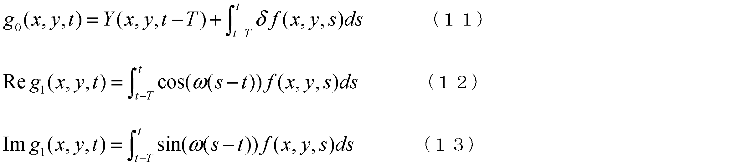
そして、参照信号の性質を考慮すると、以下に示す数式(9),(10)が成立する。

数式(9),(10)の関係を用いつつ、数式(5)~数式(7)を定数項と変位項との数式に書き換えると、以下の数式(11)~数式(13)のように表現できる。
![]()
Considering the properties of the reference signal, the following formulas (9) and (10) hold.
While using the relationships of formulas (9) and (10), if formulas (5) to (7) are rewritten into formulas of a constant term and a displacement term, the following formulas (11) to (13) are obtained. can be expressed.
イベントベースセンサにおいて、以下の数式(14)に示されるように、時間相関カメラの光ダイオードの電流をイベント信号に置き換える。
![]()
これにより、数式(11)~数式(13)は、以下の数式(15)~数式(17)のように表現することができる。
In an event-based sensor, the event signal replaces the photodiode current of the time-correlated camera, as shown in equation (14) below.
![]()
Accordingly, Equations (11) to (13) can be expressed as Equations (15) to (17) below.

数式(15)~数式(17)に示されるように、相関を取得する期間(周期T)の間に発生しているイベントを用いて時間相関信号を出力できる。
As shown in Equations (15) to (17), a time correlation signal can be output using an event that occurs during the period (cycle T) in which correlation is acquired.
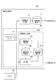
(イメージセンサの構成)
図1は、第1実施形態に係るイメージセンサを備える画像生成装置の構成概要を説明するブロック図である。図1に示される画像生成装置10は、一例として、CPU(Central Processing Unit)、ROM(Read OnlyMemory)、RAM(Random Access Memory)などを備える一般的なコンピュータとして構成される。画像生成装置10は、イベントベースセンサ11、強度画像更新部12、強度画像記憶部13、及び、相関画像生成部14を備える。イメージセンサ1は、イベントベースセンサ11及び相関画像生成部14を含んで構成される。
(Configuration of image sensor)
FIG. 1 is a block diagram for explaining the outline of the configuration of an image generation device having an image sensor according to the first embodiment. The
イベントベースセンサ11は、上述したとおり、撮像範囲内の輝度変化を検出し、イベント信号を非同期に出力する。強度画像記憶部13は、強度画像を記憶する。強度画像更新部12は、イベントベースセンサ11により出力されたイベント信号に基づいて、強度画像記憶部13に記憶された強度画像を更新する。つまり、イベントベースセンサ11、強度画像更新部12及び強度画像記憶部13によって一般的なイベントカメラの機能が実現する。
As described above, the event-based
相関画像生成部14は、イベントベースセンサ11により出力されたイベント信号と所定周期の参照信号とに基づいて、イベント信号と参照信号との画素ごとの相関を示す相関画像を生成する。具体的な一例として、相関画像生成部14は、上述した数式(15)~数式(17)を用いて相関画像を生成する。
Based on the event signal output from the event-based
以上のように構成された画像生成装置10は、イベントベースセンサ11を用いて時間相関イメージセンサと等価な強度画像g0(t)及び相関画像g1(t)を出力することができる。
The
(第1実施形態のまとめ)
イメージセンサ1においては、イベントベースセンサ11によって画素ごとの輝度変化がイベントとして検出される。輝度変化は、時間相関イメージセンサのキャパシタの容量変化に相当する。このため、イメージセンサ1は、イベントベースセンサ11を用いることで、キャパシタを備える必要がなくなることから、キャパシタの容量上限に起因したダイナミックレンジの制限が解消する。そして、イベント信号は、イベント検出のタイミング、つまり非同期で出力される。相関画像は、非同期のイベント信号と所定周期の参照信号とに基づいて生成される。このように、相関画像の全画素が連続的に生成されるのではなく、イベントに対応する相関画像の画素のみが非同期に生成(更新)される。このため、イメージセンサ1は、相関画像の全画素を連続的に生成する場合と比べて、計算コストを低減することができる。
(Summary of the first embodiment)
In the
[第2実施形態]
第2実施形態に係るイメージセンサ1Aは、第1実施形態に係るイメージセンサ1と比較して、相関画像生成部の機能が一部相違し、その他は同一である。第2実施形態においては、第1実施形態と重複する説明は省略し、相違点を中心に説明する。
[Second embodiment]
An
図2は、第2実施形態に係るイメージセンサを備える画像生成装置の構成概要を説明するブロック図である。図2に示されるように、画像生成装置10Aは、イメージセンサ1Aを備える。イメージセンサ1Aは、イベントベースセンサ11及び相関画像生成部14Aを備える。相関画像生成部14Aは、バッファ更新部140、バッファ141及び生成部142を備える。
FIG. 2 is a block diagram for explaining the outline of the configuration of an image generation device having an image sensor according to the second embodiment. As shown in FIG. 2, the
バッファ141は、イベントベースセンサ11により出力されたイベント信号を記憶する。バッファ更新部140は、バッファ141に記憶されるイベント信号が、任意の基準時刻から少なくとも所定周期だけ過去に遡った所定期間においてイベントベースセンサにより出力されたイベント信号となるように、バッファ141を更新する。基準時刻は、予め定義された時刻であり、一例として現在時刻である。基準時刻は、現在時刻から前後した時刻であってもよい。所定周期は、上述した参照信号の周期Tである。バッファ更新部140は、一例として、所定期間分のイベント信号を先入後出法によってバッファ141に格納する。これにより、バッファ141は、相関を取得する期間(周期T)分の最新のイベント信号を常に保持することができる。
The
生成部142は、バッファ141に記憶されたイベント信号に基づいて相関画像を生成する。具体的な一例として、相関画像生成部14は、上述した数式(15)~数式(17)を用いて相関画像を生成する。その他の構成は、第1実施形態のイメージセンサ1と同一である。
A
相関画像生成部14は、連続的に相関画像を生成する場合、積分の計算コストを低減するために、漸化式型に定式化された数式を用いてもよい。数式(15)~数式(17)は、時刻tから経過時間δtだけ経過した場合、以下のように表すことができる。

数式(18)~数式(20)を変形し、経過時間δtが相関を取得する周期Tよりも十分小さい場合を仮定することにより、以下の漸化式(21)が得られる。

漸化式(21)は、相関画像を短周期(δt<<T)で更新する場合に適用することができる。漸化式(21)を用いることにより、積分の演算を、前回値を用いた単純な掛け算と足し算に落とし込むことができる。これにより、演算コストを低減することができる。
The following recurrence formula (21) is obtained by modifying the formulas (18) to (20) and assuming that the elapsed time δt is sufficiently smaller than the period T for acquiring the correlation.
Recurrence formula (21) can be applied when the correlation image is updated in a short period (δt<<T). By using the recurrence formula (21), the calculation of integration can be reduced to simple multiplication and addition using the previous value. Thereby, the calculation cost can be reduced.
[第2実施形態のまとめ]
相関を取得する期間分のイベント信号が常にバッファ141に保持されるため、生成部142は、任意のタイミングであっても相関画像を生成することができる。第1実施形態において説明されたとおり、時間相関イメージセンサにおいては、相関画像の出力タイミングがシャッターの開放時間の周期タイミングに限定されていた。このイメージセンサ1Aは、バッファ141を備えることで、相関画像を任意のタイミングで出力することができる。
[Summary of the second embodiment]
Since the
[第3実施形態]
第3実施形態に係るイメージセンサ1Bは、第1及び第2実施形態に係るイメージセンサ1,1Aと比較して、相関画像生成部の機能が一部相違し、その他は同一である。第3実施形態においては、第1及び第2実施形態と重複する説明は省略し、相違点を中心に説明する。
[Third Embodiment]
The
第2実施形態に係るイメージセンサ1Aにおいては、バッファ141を備えることで相関画像を任意のタイミングで出力する構成となった。以下では、バッファ141を省略する方法を考察する。
In the
関数X(s)の区分積分は、以下のように指数関数で重み付けた積分によって近似できる。
![]()
上記式を適用し、時間相関信号の区分積分を、指数関数で重み付けた積分によって近似することにより、時刻t-Tに限定された積分区間の計算を消し去ることができる。具体的に、数式(15)~数式(17)は、以下のように簡略化することができる。

さらに、数式(22)~数式(24)を、第2実施形態において説明した漸化式(21)のように書き下すと、以下の漸化式(25)となる。

![]()
By applying the above equation and approximating the piecewise integral of the time-correlated signal by an exponentially weighted integral, the calculation of the integral interval limited to time tT can be eliminated. Specifically, Equations (15) to (17) can be simplified as follows.
Further, when the formulas (22) to (24) are written down like the recurrence formula (21) described in the second embodiment, the following recurrence formula (25) is obtained.
時間相関信号g1(x,y)は、イベントベースセンサ11からイベント信号が出力される度に、漸化式(25)を用いて更新される。前回のイベント発生時刻をsm(x,y)とすると、漸化式(25)における経過時間δtは、t-sm(x,y)で表現される。なお、以下では、イベント発生時刻、イベント信号の受信時刻、相関画像の更新時刻にタイムラグはなく、全て同一タイミングであるとして説明する。漸化式(25)に、イベント信号と、前回の時間相関信号と、前回のイベント発生時刻sm(x,y)と、参照信号の周期Tとを代入して演算することにより、今回の時間相関信号を得ることができる。これにより、常に最新の時間相関信号を得ることになるので、周期T分のイベント信号を保有する必要がない。このため、イベント信号を記録するためのバッファ141を省略することができる。
The time-correlated signal g 1 (x, y) is updated using the recurrence formula (25) each time the event-based
相関画像の読出しは、相関画像の更新(記憶)とは独立して行うことができる。前回のイベント発生時刻sm(x,y)から、読出し指令を受信した時刻tまでの経過時間をτとする。前回のイベント信号受信時の時間相関信号g1(x,y)を以下の数式(26),(27)に従い修正し、相関画像として出力する。

これにより、任意のタイミングで時間相関信号を得ることができる。
The reading of the correlation image can be done independently of the updating (storage) of the correlation image. Let τ be the elapsed time from the previous event occurrence time s m (x, y) to the time t when the read command is received. The time-correlated signal g 1 (x, y) at the time of receiving the previous event signal is corrected according to the following formulas (26) and (27) and output as a correlation image.
Thereby, a time-correlated signal can be obtained at arbitrary timing.
(イメージセンサの構成)
図3は、第3実施形態に係るイメージセンサを備える画像生成装置の構成概要を説明するブロック図である。図3に示されるように、イメージセンサ1Bは、イベントベースセンサ11及び相関画像生成部14Bを備える。相関画像生成部14Bは、相関画像更新部143(画像更新部の一例)、相関時間記憶部144、相関画像記憶部145(記憶部の一例)及び読出部146を備える。
(Configuration of image sensor)
FIG. 3 is a block diagram for explaining the outline of the configuration of an image generation device having an image sensor according to the third embodiment. As shown in FIG. 3, the
相関時間記憶部144は、参照信号の周期Tを記憶する。相関画像記憶部145は、相関画像g1(x,y)と画素ごとの更新時刻(ここではイベント発生時刻sm(x,y)と同時刻)とを記憶する。つまり、相関画像記憶部145は、画素ごとの相関及び更新時刻を記憶する。相関画像更新部143は、イベントベースセンサ11によりイベント信号が出力される度に、相関画像記憶部145を更新する。データの更新は、データの一部修正や上書きに限定されず、データのインデックスを変更した場合(前のデータを消去せずに別な記憶域に新たなデータを書き込む場合)であってもよい。相関画像更新部143は、読出部146と同期するために、クロック20からの信号に基づいて更新時刻を決定する。
The correlation
相関画像更新部143は、イベントベースセンサ11により出力されたイベント信号と、参照信号と、相関画像記憶部145に記憶された相関画像と、更新時刻とに基づいて、相関画像記憶部145に記憶された相関画像と更新時刻とを更新する。具体的には、相関画像更新部143は、上述した漸化式(25)に、イベントベースセンサ11により出力されたイベント信号と、相関画像記憶部145に記憶された前回の時間相関信号g1(x,y)と、更新時刻(前回のイベント発生時刻sm(x,y))と、相関時間記憶部144に記憶された周期Tとを代入して、今回の時間相関信号g1(x,y)を得る。相関画像更新部143は、今回の時間相関信号g1(x,y)と、現在時刻とを用いて、相関画像記憶部145に記憶された相関画像と更新時刻とを更新する。
The correlation
読出部146は、相関画像記憶部145に記憶された相関画像と更新時刻と任意の読み出し時刻とに基づいて、読み出し時刻における相関画像を出力する。読出部146は、相関画像記憶部145に記憶された更新時刻(前回のイベント発生時刻sm(x,y))から、読出し指令を受信した読み出し時刻tまでの経過時間τを算出する。そして、経過時間τと相関時間記憶部144に記憶された周期Tとを用いて、上述した数式(26),(27)に従い、前回のイベント信号受信時の時間相関信号g1(x,y)を修正する。読出部146は、相関画像更新部143と同期するために、クロック20からの信号に基づいて時刻を決定する。
The
(更新部の動作)
図4は、相関画像記憶部の更新動作を示すフローチャートである。図4に示されるフローチャートは、画像生成装置10Bに対して画像取得指示がなされたタイミングで、相関画像更新部143により実行される。
(Operation of updating part)
FIG. 4 is a flow chart showing an update operation of the correlation image storage unit. The flowchart shown in FIG. 4 is executed by the correlation
図4に示されるように、最初にイベント発生の有無が判定される(ステップS10)。ステップS10においてイベントが発生したと判定された場合には、相関画像記憶部の更新処理へと移行する(ステップS12)。ステップS12では、相関画像記憶部145に記憶された相関画像及び更新時刻が更新される。ステップS12が終了すると、図4に示されるフローチャートは終了する。
As shown in FIG. 4, first, it is determined whether or not an event has occurred (step S10). If it is determined in step S10 that an event has occurred, the process proceeds to update processing of the correlation image storage unit (step S12). In step S12, the correlation image and update time stored in the correlation
図5は、相関画像記憶部の更新動作を説明するタイムチャートである。図5に示されるように、時刻s0(x,y)において記憶された相関画像が更新され、その後、時刻s1(x,y)において第1のイベントが発生したとする。この場合、相関画像更新部143は、相関画像記憶部145に記憶された更新時刻(時刻s0(x,y))から時刻s1(x,y)となるまでの経過時間δt1を算出する。そして、相関画像更新部143は、前回の相関画像と、第1のイベント信号と、経過時間δt1とを用いて相関画像を算出し、相関画像記憶部145に記憶された相関画像を更新する。そして、相関画像更新部143は、相関画像記憶部145に記憶された更新時刻を時刻s1(x,y)に変更する。その後、時刻s2(x,y)において第2のイベントが発生したとする。この場合、相関画像更新部143は、相関画像記憶部145に記憶された更新時刻(時刻s1(x,y))から時刻s2(x,y)となるまでの経過時間δt2を算出する。そして、相関画像更新部143は、前回の相関画像と、第2のイベント信号と、経過時間δt2とを用いて相関画像を算出し、相関画像記憶部145に記憶された相関画像を更新する。そして、相関画像更新部143は、相関画像記憶部145に記憶された更新時刻を時刻s2(x,y)に変更する。このように、イベントの発生のたびに相関画像記憶部145に格納されたデータが更新される。
FIG. 5 is a time chart for explaining the update operation of the correlation image storage unit. As shown in FIG. 5, suppose the stored correlation image is updated at time s 0 (x,y) and then the first event occurs at time s 1 (x,y). In this case, the correlation
(第3実施形態のまとめ)
相関画像記憶部145に記憶された相関画像がイベント発生の度に更新され、更新時刻が記憶される。更新時刻が記憶されることにより、イベント信号に含まれる画素値の変化は、前回のイベント発生からの経過時間における画素値の変化として捉えることができる。よって、このイメージセンサ1Bは、最新の相関画像を保持することができる。そして、読出部146によって、更新時刻に基づいて読み出し時刻における相関画像が得られる。このため、このイメージセンサ1Bは、任意の読み出しタイミングで画素を出力することができる。
(Summary of the third embodiment)
The correlation image stored in the correlation
本発明は上記実施形態に限定されるものではない。本発明は、その要旨を逸脱しない範囲で様々な変形が可能である。 The present invention is not limited to the above embodiments. Various modifications are possible for the present invention without departing from the gist thereof.
CPUなどの演算装置がプログラムを実行することにより実現される機能は、論理回路などによって実現してもよい。実施形態においてはイベントベースセンサの出力は輝度信号であるとして記載したが、上記実施形態に係るイベントベースセンサにおいて、各画素に適切なカラーフィルタが追加されることにより、カラーイベントベースセンサとして機能させてもよい。 A function realized by executing a program by an arithmetic unit such as a CPU may be realized by a logic circuit or the like. In the embodiments, the output of the event-based sensor is described as a luminance signal, but in the event-based sensor according to the above-described embodiments, by adding an appropriate color filter to each pixel, it functions as a color event-based sensor. may
1,1A,1B…イメージセンサ、11…イベントベースセンサ、14…相関画像生成部、141…バッファ、142…生成部、143…相関画像更新部(画像更新部の一例)、145…相関画像記憶部(記憶部の一例)、146…読出部。
DESCRIPTION OF
Claims (3)
前記イベント信号と所定周期の参照信号とに基づいて、前記イベント信号と前記参照信号との画素ごとの相関を示す相関画像を生成する相関画像生成部と、
を備えるイメージセンサ。 A change in brightness of each pixel is detected as an event, and an event signal including a detection time when the event is detected, a pixel position where the event is generated, and a change in pixel value is output each time the event is detected. an event-based sensor that
a correlation image generating unit configured to generate a correlation image indicating the correlation of each pixel between the event signal and the reference signal based on the event signal and the reference signal of a predetermined period;
image sensor.
任意の基準時刻から少なくとも前記所定周期だけ過去に遡った所定期間において前記イベントベースセンサにより出力された、前記イベント信号を記憶するバッファと、
前記バッファに記憶された前記イベント信号に基づいて前記相関画像を生成する生成部と、
を有する請求項1に記載のイメージセンサ。 The correlation image generation unit is
a buffer that stores the event signal output by the event-based sensor in a predetermined period that goes back at least the predetermined period from an arbitrary reference time;
a generator that generates the correlation image based on the event signal stored in the buffer;
The image sensor of claim 1, comprising:
前記相関画像と画素ごとの更新時刻とを記憶する記憶部と、
前記イベントベースセンサにより前記イベント信号が出力される度に、出力された前記イベント信号と前記参照信号と前記記憶部に記憶された前記相関画像と前記更新時刻とに基づいて、前記記憶部に記憶された前記相関画像と前記更新時刻とを更新する画像更新部と、
前記記憶部に記憶された前記相関画像と前記更新時刻と任意の読み出し時刻とに基づいて、前記読み出し時刻における前記相関画像を出力する読出部と、
を有する請求項1に記載のイメージセンサ。 The correlation image generation unit is
a storage unit that stores the correlation image and an update time for each pixel;
Each time the event signal is output by the event-based sensor, the stored event signal is stored in the storage unit based on the output event signal, the reference signal, the correlation image stored in the storage unit, and the update time. an image updating unit that updates the correlated image and the update time;
a readout unit that outputs the correlation image at the readout time based on the correlation image, the update time, and an arbitrary readout time stored in the storage unit;
The image sensor of claim 1, comprising:
Priority Applications (3)
| Application Number | Priority Date | Filing Date | Title |
|---|---|---|---|
| JP2019145685A JP7120180B2 (en) | 2019-08-07 | 2019-08-07 | image sensor |
| US16/941,888 US11212469B2 (en) | 2019-08-07 | 2020-07-29 | Image sensor |
| CN202010771439.XA CN112351226B (en) | 2019-08-07 | 2020-08-04 | Image sensor |
Applications Claiming Priority (1)
| Application Number | Priority Date | Filing Date | Title |
|---|---|---|---|
| JP2019145685A JP7120180B2 (en) | 2019-08-07 | 2019-08-07 | image sensor |
Publications (2)
| Publication Number | Publication Date |
|---|---|
| JP2021026621A JP2021026621A (en) | 2021-02-22 |
| JP7120180B2 true JP7120180B2 (en) | 2022-08-17 |
Family
ID=74358300
Family Applications (1)
| Application Number | Title | Priority Date | Filing Date |
|---|---|---|---|
| JP2019145685A Active JP7120180B2 (en) | 2019-08-07 | 2019-08-07 | image sensor |
Country Status (3)
| Country | Link |
|---|---|
| US (1) | US11212469B2 (en) |
| JP (1) | JP7120180B2 (en) |
| CN (1) | CN112351226B (en) |
Citations (4)
| Publication number | Priority date | Publication date | Assignee | Title |
|---|---|---|---|---|
| JP2007305061A (en) | 2006-05-15 | 2007-11-22 | Univ Of Tokyo | Moving object information acquisition device and image acquisition device |
| JP2010510732A (en) | 2006-11-23 | 2010-04-02 | エーアイティー オーストリアン インスティテュート オブ テクノロジー ゲゼルシャフト ミット ベシュレンクテル ハフツング | Method for generating an image in electronic form, image element for image sensor for image generation and image sensor |
| JP2017521746A (en) | 2014-04-30 | 2017-08-03 | サントル ナスィオナル ド ラ ルシェルシュ スィアンティフィク(セ.エン.エル.エス.) | How to track the shape in a scene observed by an asynchronous light sensor |
| JP2018509847A (en) | 2015-03-16 | 2018-04-05 | ユニヴェルシテ・ピエール・エ・マリ・キュリ・(パリ・6) | Method for processing asynchronous signals |
Family Cites Families (10)
| Publication number | Priority date | Publication date | Assignee | Title |
|---|---|---|---|---|
| TWI458346B (en) * | 2008-06-10 | 2014-10-21 | Univ Tohoku | Solid - state photographic element and its driving method |
| JP4626692B2 (en) * | 2008-09-12 | 2011-02-09 | ソニー株式会社 | Object detection apparatus, imaging apparatus, object detection method, and program |
| EP2763393A4 (en) * | 2012-01-06 | 2015-07-01 | Asahi Chemical Ind | Imaging device and information processing device |
| EP2677500B1 (en) * | 2012-06-19 | 2021-06-23 | Samsung Electronics Co., Ltd. | Event-based image processing apparatus and method |
| US9767571B2 (en) * | 2013-07-29 | 2017-09-19 | Samsung Electronics Co., Ltd. | Apparatus and method for analyzing image including event information |
| KR102421141B1 (en) * | 2015-10-30 | 2022-07-14 | 삼성전자주식회사 | Apparatus and method for storing event signal and image and operating method of vision sensor for transmitting event signal to the apparatus |
| WO2018037079A1 (en) * | 2016-08-24 | 2018-03-01 | Universität Zürich | Simultaneous localization and mapping with an event camera |
| EP3664041A4 (en) * | 2017-07-31 | 2020-07-22 | JVCKENWOOD Corporation | Image recording device, image recording method, and image recording program |
| WO2019067054A1 (en) * | 2017-09-28 | 2019-04-04 | Apple Inc. | Generating static images with an event camera |
| JP7143703B2 (en) * | 2018-09-25 | 2022-09-29 | トヨタ自動車株式会社 | Image processing device |
-
2019
- 2019-08-07 JP JP2019145685A patent/JP7120180B2/en active Active
-
2020
- 2020-07-29 US US16/941,888 patent/US11212469B2/en active Active
- 2020-08-04 CN CN202010771439.XA patent/CN112351226B/en active Active
Patent Citations (4)
| Publication number | Priority date | Publication date | Assignee | Title |
|---|---|---|---|---|
| JP2007305061A (en) | 2006-05-15 | 2007-11-22 | Univ Of Tokyo | Moving object information acquisition device and image acquisition device |
| JP2010510732A (en) | 2006-11-23 | 2010-04-02 | エーアイティー オーストリアン インスティテュート オブ テクノロジー ゲゼルシャフト ミット ベシュレンクテル ハフツング | Method for generating an image in electronic form, image element for image sensor for image generation and image sensor |
| JP2017521746A (en) | 2014-04-30 | 2017-08-03 | サントル ナスィオナル ド ラ ルシェルシュ スィアンティフィク(セ.エン.エル.エス.) | How to track the shape in a scene observed by an asynchronous light sensor |
| JP2018509847A (en) | 2015-03-16 | 2018-04-05 | ユニヴェルシテ・ピエール・エ・マリ・キュリ・(パリ・6) | Method for processing asynchronous signals |
Also Published As
| Publication number | Publication date |
|---|---|
| US20210044764A1 (en) | 2021-02-11 |
| US11212469B2 (en) | 2021-12-28 |
| CN112351226A (en) | 2021-02-09 |
| JP2021026621A (en) | 2021-02-22 |
| CN112351226B (en) | 2023-06-16 |
Similar Documents
| Publication | Publication Date | Title |
|---|---|---|
| JP7074955B2 (en) | Data speed control for event-based visual sensors | |
| CN102082914B (en) | Image processing apparatus and image processing method | |
| KR102070562B1 (en) | Event-based image processing device and method thereof | |
| CN105227838B (en) | A kind of image processing method and mobile terminal | |
| CN109903324B (en) | Depth image acquisition method and device | |
| EP3731514B1 (en) | Event camera | |
| US20100246940A1 (en) | Method of generating hdr image and electronic device using the same | |
| EP3100451B1 (en) | Improved imaging method and apparatus | |
| JP6156578B2 (en) | Control device for imaging device | |
| CN105721772A (en) | Asynchronous time domain visual information imaging method | |
| JP7120180B2 (en) | image sensor | |
| US20150264332A1 (en) | System and method for selecting a two-dimensional region of interest using a range sensor | |
| JP2009089138A (en) | Infrared ray camera | |
| JP4207588B2 (en) | Fixed pattern noise correction method and fixed pattern noise correction apparatus for infrared imaging device | |
| JP6645279B2 (en) | Imaging equipment | |
| US11563908B2 (en) | Image acquisition techniques with reduced noise using single photon avalanche diodes | |
| KR102544622B1 (en) | Frameless random-access image sensing | |
| CN115278097A (en) | Image generation method, image generation device, electronic device, and medium | |
| JP6757392B2 (en) | Image generator, image generation method and image generation program | |
| KR102530761B1 (en) | Image sensor, camera module and apparatus comprising the same | |
| US9363443B2 (en) | Processing control apparatus, processing control method and non-transitory computer-readable storage medium | |
| KR20160036974A (en) | Apparatus and method for obtaining high resolution image | |
| JP2018205678A (en) | SHAKE CORRECTION SYSTEM USING Gyro DEVICE, Gyro SENSOR DEVICE AND IMAGE SENSOR DEVICE | |
| CN110933288B (en) | Image generation method and electronic device | |
| Reichel et al. | Simulation platform for application development on a vision-system-on-chip with integrated signal processing |
Legal Events
| Date | Code | Title | Description |
|---|---|---|---|
| A621 | Written request for application examination |
Free format text: JAPANESE INTERMEDIATE CODE: A621 Effective date: 20210719 |
|
| TRDD | Decision of grant or rejection written | ||
| A01 | Written decision to grant a patent or to grant a registration (utility model) |
Free format text: JAPANESE INTERMEDIATE CODE: A01 Effective date: 20220705 |
|
| A61 | First payment of annual fees (during grant procedure) |
Free format text: JAPANESE INTERMEDIATE CODE: A61 Effective date: 20220718 |
|
| R151 | Written notification of patent or utility model registration |
Ref document number: 7120180 Country of ref document: JP Free format text: JAPANESE INTERMEDIATE CODE: R151 |