US11162402B2 - Selective catalytic reduction system - Google Patents
Selective catalytic reduction system Download PDFInfo
- Publication number
- US11162402B2 US11162402B2 US16/463,553 US201716463553A US11162402B2 US 11162402 B2 US11162402 B2 US 11162402B2 US 201716463553 A US201716463553 A US 201716463553A US 11162402 B2 US11162402 B2 US 11162402B2
- Authority
- US
- United States
- Prior art keywords
- def
- dosing unit
- hydrolysis catalyst
- controller
- scr
- Prior art date
- Legal status (The legal status is an assumption and is not a legal conclusion. Google has not performed a legal analysis and makes no representation as to the accuracy of the status listed.)
- Active, expires
Links
Images


Classifications
-
- F—MECHANICAL ENGINEERING; LIGHTING; HEATING; WEAPONS; BLASTING
- F01—MACHINES OR ENGINES IN GENERAL; ENGINE PLANTS IN GENERAL; STEAM ENGINES
- F01N—GAS-FLOW SILENCERS OR EXHAUST APPARATUS FOR MACHINES OR ENGINES IN GENERAL; GAS-FLOW SILENCERS OR EXHAUST APPARATUS FOR INTERNAL-COMBUSTION ENGINES
- F01N3/00—Exhaust or silencing apparatus having means for purifying, rendering innocuous, or otherwise treating exhaust
- F01N3/08—Exhaust or silencing apparatus having means for purifying, rendering innocuous, or otherwise treating exhaust for rendering innocuous
- F01N3/10—Exhaust or silencing apparatus having means for purifying, rendering innocuous, or otherwise treating exhaust for rendering innocuous by thermal or catalytic conversion of noxious components of exhaust
- F01N3/18—Exhaust or silencing apparatus having means for purifying, rendering innocuous, or otherwise treating exhaust for rendering innocuous by thermal or catalytic conversion of noxious components of exhaust characterised by methods of operation; Control
- F01N3/20—Exhaust or silencing apparatus having means for purifying, rendering innocuous, or otherwise treating exhaust for rendering innocuous by thermal or catalytic conversion of noxious components of exhaust characterised by methods of operation; Control specially adapted for catalytic conversion
- F01N3/206—Adding periodically or continuously substances to exhaust gases for promoting purification, e.g. catalytic material in liquid form, NOx reducing agents
- F01N3/2066—Selective catalytic reduction [SCR]
-
- B—PERFORMING OPERATIONS; TRANSPORTING
- B01—PHYSICAL OR CHEMICAL PROCESSES OR APPARATUS IN GENERAL
- B01D—SEPARATION
- B01D53/00—Separation of gases or vapours; Recovering vapours of volatile solvents from gases; Chemical or biological purification of waste gases, e.g. engine exhaust gases, smoke, fumes, flue gases, aerosols
- B01D53/34—Chemical or biological purification of waste gases
- B01D53/92—Chemical or biological purification of waste gases of engine exhaust gases
- B01D53/94—Chemical or biological purification of waste gases of engine exhaust gases by catalytic processes
- B01D53/9404—Removing only nitrogen compounds
- B01D53/9409—Nitrogen oxides
- B01D53/9431—Processes characterised by a specific device
-
- B—PERFORMING OPERATIONS; TRANSPORTING
- B01—PHYSICAL OR CHEMICAL PROCESSES OR APPARATUS IN GENERAL
- B01D—SEPARATION
- B01D53/00—Separation of gases or vapours; Recovering vapours of volatile solvents from gases; Chemical or biological purification of waste gases, e.g. engine exhaust gases, smoke, fumes, flue gases, aerosols
- B01D53/34—Chemical or biological purification of waste gases
- B01D53/92—Chemical or biological purification of waste gases of engine exhaust gases
- B01D53/94—Chemical or biological purification of waste gases of engine exhaust gases by catalytic processes
- B01D53/9495—Controlling the catalytic process
-
- F—MECHANICAL ENGINEERING; LIGHTING; HEATING; WEAPONS; BLASTING
- F01—MACHINES OR ENGINES IN GENERAL; ENGINE PLANTS IN GENERAL; STEAM ENGINES
- F01N—GAS-FLOW SILENCERS OR EXHAUST APPARATUS FOR MACHINES OR ENGINES IN GENERAL; GAS-FLOW SILENCERS OR EXHAUST APPARATUS FOR INTERNAL-COMBUSTION ENGINES
- F01N3/00—Exhaust or silencing apparatus having means for purifying, rendering innocuous, or otherwise treating exhaust
- F01N3/08—Exhaust or silencing apparatus having means for purifying, rendering innocuous, or otherwise treating exhaust for rendering innocuous
- F01N3/10—Exhaust or silencing apparatus having means for purifying, rendering innocuous, or otherwise treating exhaust for rendering innocuous by thermal or catalytic conversion of noxious components of exhaust
- F01N3/18—Exhaust or silencing apparatus having means for purifying, rendering innocuous, or otherwise treating exhaust for rendering innocuous by thermal or catalytic conversion of noxious components of exhaust characterised by methods of operation; Control
- F01N3/20—Exhaust or silencing apparatus having means for purifying, rendering innocuous, or otherwise treating exhaust for rendering innocuous by thermal or catalytic conversion of noxious components of exhaust characterised by methods of operation; Control specially adapted for catalytic conversion
- F01N3/206—Adding periodically or continuously substances to exhaust gases for promoting purification, e.g. catalytic material in liquid form, NOx reducing agents
- F01N3/208—Control of selective catalytic reduction [SCR], e.g. by adjusting the dosing of reducing agent
-
- F—MECHANICAL ENGINEERING; LIGHTING; HEATING; WEAPONS; BLASTING
- F01—MACHINES OR ENGINES IN GENERAL; ENGINE PLANTS IN GENERAL; STEAM ENGINES
- F01N—GAS-FLOW SILENCERS OR EXHAUST APPARATUS FOR MACHINES OR ENGINES IN GENERAL; GAS-FLOW SILENCERS OR EXHAUST APPARATUS FOR INTERNAL-COMBUSTION ENGINES
- F01N2240/00—Combination or association of two or more different exhaust treating devices, or of at least one such device with an auxiliary device, not covered by indexing codes F01N2230/00 or F01N2250/00, one of the devices being
- F01N2240/40—Combination or association of two or more different exhaust treating devices, or of at least one such device with an auxiliary device, not covered by indexing codes F01N2230/00 or F01N2250/00, one of the devices being a hydrolysis catalyst
-
- F—MECHANICAL ENGINEERING; LIGHTING; HEATING; WEAPONS; BLASTING
- F01—MACHINES OR ENGINES IN GENERAL; ENGINE PLANTS IN GENERAL; STEAM ENGINES
- F01N—GAS-FLOW SILENCERS OR EXHAUST APPARATUS FOR MACHINES OR ENGINES IN GENERAL; GAS-FLOW SILENCERS OR EXHAUST APPARATUS FOR INTERNAL-COMBUSTION ENGINES
- F01N2610/00—Adding substances to exhaust gases
- F01N2610/02—Adding substances to exhaust gases the substance being ammonia or urea
-
- F—MECHANICAL ENGINEERING; LIGHTING; HEATING; WEAPONS; BLASTING
- F01—MACHINES OR ENGINES IN GENERAL; ENGINE PLANTS IN GENERAL; STEAM ENGINES
- F01N—GAS-FLOW SILENCERS OR EXHAUST APPARATUS FOR MACHINES OR ENGINES IN GENERAL; GAS-FLOW SILENCERS OR EXHAUST APPARATUS FOR INTERNAL-COMBUSTION ENGINES
- F01N2610/00—Adding substances to exhaust gases
- F01N2610/14—Arrangements for the supply of substances, e.g. conduits
- F01N2610/1453—Sprayers or atomisers; Arrangement thereof in the exhaust apparatus
- F01N2610/146—Control thereof, e.g. control of injectors or injection valves
-
- F—MECHANICAL ENGINEERING; LIGHTING; HEATING; WEAPONS; BLASTING
- F01—MACHINES OR ENGINES IN GENERAL; ENGINE PLANTS IN GENERAL; STEAM ENGINES
- F01N—GAS-FLOW SILENCERS OR EXHAUST APPARATUS FOR MACHINES OR ENGINES IN GENERAL; GAS-FLOW SILENCERS OR EXHAUST APPARATUS FOR INTERNAL-COMBUSTION ENGINES
- F01N2900/00—Details of electrical control or of the monitoring of the exhaust gas treating apparatus
- F01N2900/06—Parameters used for exhaust control or diagnosing
- F01N2900/16—Parameters used for exhaust control or diagnosing said parameters being related to the exhaust apparatus, e.g. particulate filter or catalyst
-
- Y—GENERAL TAGGING OF NEW TECHNOLOGICAL DEVELOPMENTS; GENERAL TAGGING OF CROSS-SECTIONAL TECHNOLOGIES SPANNING OVER SEVERAL SECTIONS OF THE IPC; TECHNICAL SUBJECTS COVERED BY FORMER USPC CROSS-REFERENCE ART COLLECTIONS [XRACs] AND DIGESTS
- Y02—TECHNOLOGIES OR APPLICATIONS FOR MITIGATION OR ADAPTATION AGAINST CLIMATE CHANGE
- Y02A—TECHNOLOGIES FOR ADAPTATION TO CLIMATE CHANGE
- Y02A50/00—TECHNOLOGIES FOR ADAPTATION TO CLIMATE CHANGE in human health protection, e.g. against extreme weather
- Y02A50/20—Air quality improvement or preservation, e.g. vehicle emission control or emission reduction by using catalytic converters
-
- Y—GENERAL TAGGING OF NEW TECHNOLOGICAL DEVELOPMENTS; GENERAL TAGGING OF CROSS-SECTIONAL TECHNOLOGIES SPANNING OVER SEVERAL SECTIONS OF THE IPC; TECHNICAL SUBJECTS COVERED BY FORMER USPC CROSS-REFERENCE ART COLLECTIONS [XRACs] AND DIGESTS
- Y02—TECHNOLOGIES OR APPLICATIONS FOR MITIGATION OR ADAPTATION AGAINST CLIMATE CHANGE
- Y02T—CLIMATE CHANGE MITIGATION TECHNOLOGIES RELATED TO TRANSPORTATION
- Y02T10/00—Road transport of goods or passengers
- Y02T10/10—Internal combustion engine [ICE] based vehicles
- Y02T10/12—Improving ICE efficiencies
Definitions
- This invention relates to selective catalytic reduction systems for treating diesel engine exhaust gases.
- SCR Selective catalytic reduction
- SCR systems which dose DEF into the exhaust passage have been proposed, Such systems are sometimes referred to as “wet spray” systems and inject a spray of aqueous urea into the exhaust gas where it decomposes to form ammonia.
- An example of such a system is shown in US2008/022654, U.S. '654 discloses a SCR system which includes a SCR catalyst and a reagent injector that injects DEF onto the SCR catalyst downstream of the SCR catalyst.
- the reagent injector injects DEF at a frequency of between 1 Hz and 10 Hz.
- thermolysis of urea can also lead to urea deposits forming in the exhaust passage, and unreacted urea or ammonia passing untreated out of the exhaust passage in an ammonia slip event if, for example, an exhaust inlet temperature rise occurs.
- Prior SCR systems inject a volume of DEF using a DEF injector at a flow rate governed by a supply pressure of the DEF with only short periods of time of typically less than one second between injection events. This does not allow the temperature of the hydrolysis catalyst to recover at low and medium temperature conditions and/or flow rate conditions, which ultimately suppresses ammonia production, Known SCR systems tend to use injection pulse width modulation frequencies which are as high as possible.
- a selective catalytic reduction (SCR) system for treating exhaust gas in an exhaust passage, the system comprising:
- DEF diesel exhaust fluid
- controller adapted to control DEF dosing by the dosing unit, wherein the controller is configured to control the DEF dosing unit such that the DEF is injected at a modulated frequency of less than or equal to 1 Hertz.
- an exhaust apparatus for a vehicle including a SCR system in accordance with the first aspect of the invention.
- a vehicle including a SCR system in accordance with the first aspect of the invention.
- a fourth aspect of the invention there is provided a method of treating exhaust gas in an exhaust passage using an SCR system, the method comprising the steps of:
- DEF diesel exhaust fluid
- DEF dosing such that the DEF is injected at a modulated frequency of less than or equal to 1 Hertz.
- FIG. 1 is a schematic diagram of a selective catalytic reduction (SCR) system
- FIG. 2 shows an example dosing pattern of the SCR system of FIG. 1 ;
- FIG. 3 shows a graph of ammonia production for various example dosing rates.
- a selective catalytic reduction (SCR) system 10 The system 10 is located in an exhaust passage 12 which conveys exhaust gas away from an engine (not shown) of a vehicle (not shown).
- the exhaust gas first passes through a diesel oxidation catalyst (DOC) 14 of a known type, which may optionally form part of the system 10 .
- DOC diesel oxidation catalyst
- the DOC 14 catalyses an oxidation reaction of hydrocarbons and carbon monoxide in the exhaust gas to produce carbon dioxide and water.
- a diesel exhaust fluid (DEF) dosing unit 16 Located downstream of the DOC 14 is a diesel exhaust fluid (DEF) dosing unit 16 which is configured to inject DEF onto a hydrolysis catalyst 18 located downstream of the DOC 14 in the exhaust passage 12 .
- the DEF dosing unit 16 is of a known type, and injects DEF in the form of an aqueous urea solution.
- the hydrolysis catalyst 18 is of a known type and catalyses a hydrolysis reaction of the DEF in which ammonia and carbon dioxide are produced.
- a SCR catalyst 20 Located downstream of the hydrolysis catalyst 18 in the exhaust passage 12 is a SCR catalyst 20 , which is also of a known type.
- the SCR catalyst 20 catalyses a reduction reaction between nitrogen oxide (NOx) in the exhaust gas and the ammonia downstream of the hydrolysis catalyst 18 in which the NOx is reduced into nitrogen and water.
- the system 10 may optionally include a SCR catalyst filter 22 which is located immediately upstream of the SCR catalyst 20 .
- the SCR catalyst filter 22 is configured to prevent larger particles in the exhaust passage entering the SCR catalyst 20 .
- an optional ammonia slip (AS) catalyst 24 Located downstream of the SCR catalyst 20 in the exhaust passage 12 is an optional ammonia slip (AS) catalyst 24 of a known type which is configured to oxidise any unreacted ammonia which has passed through the SCR catalyst 20 before it can pass out of the exhaust into the atmosphere.
- AS ammonia slip
- the system 10 also includes a controller 26 which is in communication with the DEF dosing unit 16 and is configured to control a rate at which the DEF dosing unit 16 injects DEF onto the hydrolysis catalyst 18 .
- the controller 26 is also configured to control the DEF dosing unit 16 between an on state and an off state. In the on state the DEF dosing unit 16 injects DEF onto the hydrolysis catalyst 18 at a non-zero rate set by the controller 26 and in the off state DEF dosing unit does not inject DEF onto the hydrolysis catalyst 18 .
- the controller 26 is configured to employ pulse frequency modulation to control a modulated frequency of the DEF dosing unit 16 between the on and off states, and to also employ pulse width modulation to control a modulated time period in which the DEF dosing unit injects DEF fluid onto the hydrolysis catalyst 18 .
- the system 10 also includes a plurality of sensors which are in communication with the controller 26 .
- a nitrogen oxide (NOx) sensor 28 is located upstream of the hydrolysis catalyst 18 and is configured to measure NOx levels in the exhaust passage 12 .
- the NOx sensor 28 is in communication with the controller 26 .
- a first, or an inlet, temperature sensor 30 that is in communication with the controller 26 .
- the inlet temperature sensor 30 is configured to measure an exhaust gas temperature upstream of the hydrolysis catalyst 18 .
- a second temperature sensor 32 Located between the hydrolysis catalyst 18 and the SCR catalyst 20 is a second temperature sensor 32 that is in communication with the controller 26 and configured to measure a temperature value of the exhaust gas by sending a signal to the controller 26 .
- the second temperature sensor 32 may be located between the hydrolysis catalyst 18 and the SCR catalyst 20 , Alternatively, the second temperature sensor 32 may be located inside the hydrolysis catalyst 18 .
- ammonia sensor 34 located between the hydrolysis catalyst 18 and the SCR catalyst 20 is Also located between the hydrolysis catalyst 18 and the SCR catalyst 20 .
- the controller 26 controls the DEF dosing unit 16 such that the modulated frequency at which it injects DEF onto the hydrolysis catalyst 18 is less or equal to 1 Hz.
- the controller 26 controls the DEF dosing unit 16 such that it is in the on state the DEF dosing unit 16 injects DEF onto the hydrolysis catalyst 18 at a rate of 11,000 grams per hour.
- the controller 26 also adjusts the modulated frequency at which the DEF dosing unit 16 injects DEF onto the hydrolysis catalyst 18 in response to signals received from one of the first or second temperature sensors 30 , 32 , and/or the mass flow rate of the exhaust gas in the exhaust passage, which is calculated in a known manner.
- the controller 26 may control the DEF dosing unit 16 such that it increases the modulated frequency at which it injects DEF onto the hydrolysis catalyst 18 , if the temperature of the exhaust gas at the hydrolysis catalyst 18 is above a predetermined level.
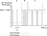
- An example dosing pattern which may be used in the system 10 is depicted as a graph in FIG. 2 .
- the minimum time for which the DEF dosing unit 16 is in the off state is 1s
- the minimum time for which the dosing unit 16 is in the on state is 1s.
- the DEF dosing unit 16 injects DEF fluid onto the hydrolysis catalyst 18 at a rate of 11,000 grams per hour when it is in the on state.
- the DEF dosing unit 16 is in the on state far periods of 1s and is in the off state for periods of 4s.
- phase B the frequency has increased, where the DEF dosing unit 16 is in the on state for periods of 1s and is in the off state for periods of 1s.
- phase C the DEF dosing unit 16 is in the on state for periods of 3s and is in the off state for periods of 1 s.
- the system according to the present invention decreases the modulated frequency of the injection events to produce more ammonia to reduce NOx.
- the temperature of the hydrolysis catalyst is allowed to recover between injection events thanks to the dosing frequency of 1 Hz or less which allows for more effective conversion of DEF into ammonia. This means that more ammonia is available for the selective catalytic reduction reaction at the SCR catalyst. Therefore, the system described above has increased NOx reduction capabilities and ammonia slip events do not occur.
- FIG. 3 shows the ammonia production for tests using various DEF dosing rates over various time periods. Ammonia production is greatest for a dosing rate of 10000 g/hr over a period of 18 seconds, wherein maximum ammonia production is approximately 900 parts per million. Ammonia production is significantly less for the lower 2000 g/hr and 5000 g/hr dosing rates which are over longer time periods of 90 and 36 seconds, respectively, wherein maximum ammonia production is approximately 700 and 590 parts per million, respectively. This shows that ammonia production is much greater for high dosing rates over short periods of time than for lower dosing rates over long periods of time.
- modulation of the DEF injection frequency may be based upon particular trigger conditions relating to the internal conditions of the hydrolysis catalyst.
- An embedded model of the hydrolysis catalyst and an estimator may use ammonia and temperature sensor readings from the hydrolysis catalyst outlet, as well as NOx sensor readings from the hydrolysis catalyst inlet in order to establish the trigger conditions.
Landscapes
- Chemical & Material Sciences (AREA)
- Engineering & Computer Science (AREA)
- Chemical Kinetics & Catalysis (AREA)
- Combustion & Propulsion (AREA)
- Health & Medical Sciences (AREA)
- Mechanical Engineering (AREA)
- Toxicology (AREA)
- General Engineering & Computer Science (AREA)
- Biomedical Technology (AREA)
- Environmental & Geological Engineering (AREA)
- Analytical Chemistry (AREA)
- General Chemical & Material Sciences (AREA)
- Oil, Petroleum & Natural Gas (AREA)
- Exhaust Gas After Treatment (AREA)
- Exhaust Gas Treatment By Means Of Catalyst (AREA)
Abstract
Description
Claims (12)
Applications Claiming Priority (4)
| Application Number | Priority Date | Filing Date | Title |
|---|---|---|---|
| EP16205949.7A EP3339590B1 (en) | 2016-12-21 | 2016-12-21 | Selective catalytic reduction system |
| EP16205949 | 2016-12-21 | ||
| EP16205949.7 | 2016-12-21 | ||
| PCT/EP2017/082201 WO2018114428A1 (en) | 2016-12-21 | 2017-12-11 | An improved selective catalytic reduction system |
Publications (2)
| Publication Number | Publication Date |
|---|---|
| US20210285352A1 US20210285352A1 (en) | 2021-09-16 |
| US11162402B2 true US11162402B2 (en) | 2021-11-02 |
Family
ID=57590383
Family Applications (1)
| Application Number | Title | Priority Date | Filing Date |
|---|---|---|---|
| US16/463,553 Active 2038-10-25 US11162402B2 (en) | 2016-12-21 | 2017-12-11 | Selective catalytic reduction system |
Country Status (5)
| Country | Link |
|---|---|
| US (1) | US11162402B2 (en) |
| EP (1) | EP3339590B1 (en) |
| JP (1) | JP2020514604A (en) |
| CN (1) | CN110073085B (en) |
| WO (1) | WO2018114428A1 (en) |
Families Citing this family (1)
| Publication number | Priority date | Publication date | Assignee | Title |
|---|---|---|---|---|
| GB2635544A (en) * | 2023-11-16 | 2025-05-21 | Perkins Engines Co Ltd | Diesel exhaust fluid injector control |
Citations (16)
| Publication number | Priority date | Publication date | Assignee | Title |
|---|---|---|---|---|
| CN1041288A (en) | 1988-07-25 | 1990-04-18 | 底古萨有限公司 | Remove the method for nitrogen oxide in the waste gas with reducing agent catalysis |
| US5849593A (en) * | 1994-11-04 | 1998-12-15 | Siemens Aktiengesellschaft | Method for metering a reagent into a flowing medium |
| US6361754B1 (en) * | 1997-03-27 | 2002-03-26 | Clean Diesel Technologies, Inc. | Reducing no emissions from an engine by on-demand generation of ammonia for selective catalytic reduction |
| JP2004108185A (en) | 2002-09-17 | 2004-04-08 | Nissan Diesel Motor Co Ltd | Exhaust emission control device for diesel engine |
| US20070214777A1 (en) | 2003-06-18 | 2007-09-20 | Allansson Eive T R | Methods Of Controlling Reductant Addition |
| WO2007142899A2 (en) | 2006-05-31 | 2007-12-13 | Tenneco Automotive Operating Company Inc. | Method and apparatus for reducing emissions in diesel engines |
| US20080022658A1 (en) | 2006-07-25 | 2008-01-31 | Gm Global Technology Operations, Inc. | Method and Apparatus for Monitoring a Urea Injection System in an Exhaust Aftertreatment System |
| CN101190410A (en) | 2006-11-29 | 2008-06-04 | 株式会社Ict | Oxidation catalyst and exhaust gas purification system using the same |
| WO2008139146A2 (en) | 2007-05-11 | 2008-11-20 | Norgren Limited | Method and apparatus for controlling gaseous hydrolysis production |
| US20090272099A1 (en) | 2008-04-30 | 2009-11-05 | Phanindra Garimella | Apparatus, system, and method for determining the degradation of an scr catalyst |
| EP2131020A2 (en) | 2008-06-06 | 2009-12-09 | Delphi Technologies, Inc. | Method of dosing reagent |
| JP2010504459A (en) | 2006-09-20 | 2010-02-12 | ロベルト・ボッシュ・ゲゼルシャフト・ミト・ベシュレンクテル・ハフツング | Actuation method of the reactant dispensing valve and apparatus for carrying out the method |
| US20100150080A1 (en) | 2008-12-17 | 2010-06-17 | Qualcomm Incorporated | Methods and apparatus for reuse of a wireless resource |
| US20110072798A1 (en) | 2009-09-28 | 2011-03-31 | Herman Andrew D | NOx CONTROL REQUEST FOR NH3 STORAGE CONTROL |
| WO2011099051A1 (en) | 2010-02-09 | 2011-08-18 | 本田技研工業株式会社 | Exhaust gas purification device for internal combustion engine |
| US10724413B2 (en) * | 2013-12-19 | 2020-07-28 | Dailer AG | Method and control assembly for operating an exhaust gas system |
Family Cites Families (8)
| Publication number | Priority date | Publication date | Assignee | Title |
|---|---|---|---|---|
| CA1298957C (en) * | 1987-01-27 | 1992-04-21 | Motonobu Kobayashi | Method for removal of nitrogen oxides from exhaust gas of diesel engine |
| JP3100191B2 (en) * | 1991-09-02 | 2000-10-16 | 三菱重工業株式会社 | Flue gas denitration equipment |
| US7497076B2 (en) * | 2002-05-07 | 2009-03-03 | Extengine Transport Systems | Emission control system |
| DE102004050022B4 (en) * | 2004-10-13 | 2012-01-05 | L'orange Gmbh | Device for cooling a nozzle for the metered injection of a reducing agent into the exhaust gas tract of an internal combustion engine |
| CN201013431Y (en) * | 2007-02-12 | 2008-01-30 | 潍柴动力股份有限公司 | Large-displacement engine SCR after-treatment device |
| JP2011117458A (en) * | 2011-03-09 | 2011-06-16 | Toyota Motor Corp | Exhaust emission control device of internal combustion device |
| CN102635427A (en) * | 2012-04-24 | 2012-08-15 | 吉林大学 | Sectional type ammonia generating device for discomposing solid urea |
| US9333462B2 (en) * | 2012-05-03 | 2016-05-10 | Scania Cv Ab | Exhaust aftertreatment system and method pertaining to such a system |
-
2016
- 2016-12-21 EP EP16205949.7A patent/EP3339590B1/en active Active
-
2017
- 2017-12-11 WO PCT/EP2017/082201 patent/WO2018114428A1/en not_active Ceased
- 2017-12-11 US US16/463,553 patent/US11162402B2/en active Active
- 2017-12-11 CN CN201780077529.5A patent/CN110073085B/en active Active
- 2017-12-11 JP JP2019530726A patent/JP2020514604A/en active Pending
Patent Citations (21)
| Publication number | Priority date | Publication date | Assignee | Title |
|---|---|---|---|---|
| CN1041288A (en) | 1988-07-25 | 1990-04-18 | 底古萨有限公司 | Remove the method for nitrogen oxide in the waste gas with reducing agent catalysis |
| US5849593A (en) * | 1994-11-04 | 1998-12-15 | Siemens Aktiengesellschaft | Method for metering a reagent into a flowing medium |
| US6361754B1 (en) * | 1997-03-27 | 2002-03-26 | Clean Diesel Technologies, Inc. | Reducing no emissions from an engine by on-demand generation of ammonia for selective catalytic reduction |
| JP2004108185A (en) | 2002-09-17 | 2004-04-08 | Nissan Diesel Motor Co Ltd | Exhaust emission control device for diesel engine |
| US20070214777A1 (en) | 2003-06-18 | 2007-09-20 | Allansson Eive T R | Methods Of Controlling Reductant Addition |
| CN101454543A (en) | 2006-05-31 | 2009-06-10 | 坦尼科汽车操作有限公司 | Method and apparatus for reducing emissions in diesel engines |
| US20080022654A1 (en) | 2006-05-31 | 2008-01-31 | Broderick R G | Method And Apparatus For Reducing Emissions In Diesel Engines |
| WO2007142899A2 (en) | 2006-05-31 | 2007-12-13 | Tenneco Automotive Operating Company Inc. | Method and apparatus for reducing emissions in diesel engines |
| EP2826967A1 (en) | 2006-05-31 | 2015-01-21 | Tenneco Automotive Operating Company Inc. | Method and apparatus for reducing emissions in diesel engines |
| US20080022658A1 (en) | 2006-07-25 | 2008-01-31 | Gm Global Technology Operations, Inc. | Method and Apparatus for Monitoring a Urea Injection System in an Exhaust Aftertreatment System |
| JP2010504459A (en) | 2006-09-20 | 2010-02-12 | ロベルト・ボッシュ・ゲゼルシャフト・ミト・ベシュレンクテル・ハフツング | Actuation method of the reactant dispensing valve and apparatus for carrying out the method |
| CN101190410A (en) | 2006-11-29 | 2008-06-04 | 株式会社Ict | Oxidation catalyst and exhaust gas purification system using the same |
| WO2008139146A2 (en) | 2007-05-11 | 2008-11-20 | Norgren Limited | Method and apparatus for controlling gaseous hydrolysis production |
| US20090272099A1 (en) | 2008-04-30 | 2009-11-05 | Phanindra Garimella | Apparatus, system, and method for determining the degradation of an scr catalyst |
| EP2131020A2 (en) | 2008-06-06 | 2009-12-09 | Delphi Technologies, Inc. | Method of dosing reagent |
| JP2009293619A (en) | 2008-06-06 | 2009-12-17 | Delphi Technologies Inc | Reagent metering supplying system and reagent metering supplying method |
| US20100150080A1 (en) | 2008-12-17 | 2010-06-17 | Qualcomm Incorporated | Methods and apparatus for reuse of a wireless resource |
| US20110072798A1 (en) | 2009-09-28 | 2011-03-31 | Herman Andrew D | NOx CONTROL REQUEST FOR NH3 STORAGE CONTROL |
| WO2011099051A1 (en) | 2010-02-09 | 2011-08-18 | 本田技研工業株式会社 | Exhaust gas purification device for internal combustion engine |
| DE112010005244T5 (en) | 2010-02-09 | 2012-11-15 | Honda Motor Co., Ltd. | Emission cleaning device |
| US10724413B2 (en) * | 2013-12-19 | 2020-07-28 | Dailer AG | Method and control assembly for operating an exhaust gas system |
Non-Patent Citations (1)
| Title |
|---|
| International Search Report for Application No. PCT/EP2017/082201; dated Mar. 6, 2018. |
Also Published As
| Publication number | Publication date |
|---|---|
| WO2018114428A1 (en) | 2018-06-28 |
| CN110073085A (en) | 2019-07-30 |
| EP3339590A1 (en) | 2018-06-27 |
| US20210285352A1 (en) | 2021-09-16 |
| EP3339590B1 (en) | 2019-08-28 |
| CN110073085B (en) | 2021-12-31 |
| JP2020514604A (en) | 2020-05-21 |
Similar Documents
| Publication | Publication Date | Title |
|---|---|---|
| US9333462B2 (en) | Exhaust aftertreatment system and method pertaining to such a system | |
| JP6257941B2 (en) | Method for reducing nitrogen oxides in diesel engine exhaust gas | |
| US9371767B2 (en) | Soot load determination system | |
| US7736595B2 (en) | Dosing agent injection control for selective catalytic reduction catalysts | |
| US8834821B2 (en) | Control techniques for an SCR aftertreatment system | |
| US10480373B2 (en) | Techniques for control of an SCR aftertreatment system in response to an ammonia slip condition | |
| KR20170039579A (en) | Method for the operation of an exhaust gas aftertreatment system | |
| US10247076B2 (en) | Exhaust treatment system including ammonia storage control system | |
| US10145284B2 (en) | Exhaust after-treatment system including sliding mode ammonia controller | |
| JP2012107536A (en) | CONTROL METHOD AND DEVICE OF NOx CLEANING DEVICE | |
| CN104696051B (en) | A kind of engine exhaust processing system and exhaust gas treating method | |
| US11105236B2 (en) | Selective catalytic reduction system | |
| US10598112B2 (en) | Method for adapting the characteristic curve of the nitrogen oxide sensor in an internal combustion engine | |
| KR20130117869A (en) | Method for supervision and adjustment of an exhaust posttreatment system | |
| US11162402B2 (en) | Selective catalytic reduction system | |
| EP2885514B1 (en) | Exhaust aftertreatment system and method pertaining to such a system | |
| US10400644B2 (en) | Method and system for adjusting reductant delivery into a selective catalytic reduction with a filter (SCRF) device | |
| KR100820395B1 (en) | Nitrogen oxide reduction method and apparatus for exhaust gas | |
| JP2016128695A (en) | Control device for nox purification device |
Legal Events
| Date | Code | Title | Description |
|---|---|---|---|
| FEPP | Fee payment procedure |
Free format text: ENTITY STATUS SET TO UNDISCOUNTED (ORIGINAL EVENT CODE: BIG.); ENTITY STATUS OF PATENT OWNER: LARGE ENTITY |
|
| AS | Assignment |
Owner name: PERKINS ENGINES COMPANY LIMITED, ENGLAND Free format text: ASSIGNMENT OF ASSIGNORS INTEREST;ASSIGNORS:SHEAD, LEO;EDEN, ALEXIS;SILVER, RONALD;AND OTHERS;SIGNING DATES FROM 20190612 TO 20190709;REEL/FRAME:050177/0850 |
|
| STPP | Information on status: patent application and granting procedure in general |
Free format text: NOTICE OF ALLOWANCE MAILED -- APPLICATION RECEIVED IN OFFICE OF PUBLICATIONS |
|
| STPP | Information on status: patent application and granting procedure in general |
Free format text: PUBLICATIONS -- ISSUE FEE PAYMENT VERIFIED |
|
| STPP | Information on status: patent application and granting procedure in general |
Free format text: PUBLICATIONS -- ISSUE FEE PAYMENT VERIFIED |
|
| STCF | Information on status: patent grant |
Free format text: PATENTED CASE |
|
| MAFP | Maintenance fee payment |
Free format text: PAYMENT OF MAINTENANCE FEE, 4TH YEAR, LARGE ENTITY (ORIGINAL EVENT CODE: M1551); ENTITY STATUS OF PATENT OWNER: LARGE ENTITY Year of fee payment: 4 |