US11162284B2 - One motor latch assembly with power cinch and power release having soft opening function - Google Patents
One motor latch assembly with power cinch and power release having soft opening function Download PDFInfo
- Publication number
- US11162284B2 US11162284B2 US15/276,926 US201615276926A US11162284B2 US 11162284 B2 US11162284 B2 US 11162284B2 US 201615276926 A US201615276926 A US 201615276926A US 11162284 B2 US11162284 B2 US 11162284B2
- Authority
- US
- United States
- Prior art keywords
- pawl
- ratchet
- cinch
- lever
- release
- Prior art date
- Legal status (The legal status is an assumption and is not a legal conclusion. Google has not performed a legal analysis and makes no representation as to the accuracy of the status listed.)
- Active, expires
Links
Images


Classifications
-
- E—FIXED CONSTRUCTIONS
- E05—LOCKS; KEYS; WINDOW OR DOOR FITTINGS; SAFES
- E05B—LOCKS; ACCESSORIES THEREFOR; HANDCUFFS
- E05B77/00—Vehicle locks characterised by special functions or purposes
- E05B77/02—Vehicle locks characterised by special functions or purposes for accident situations
- E05B77/04—Preventing unwanted lock actuation, e.g. unlatching, at the moment of collision
- E05B77/06—Preventing unwanted lock actuation, e.g. unlatching, at the moment of collision by means of inertial forces
-
- E—FIXED CONSTRUCTIONS
- E05—LOCKS; KEYS; WINDOW OR DOOR FITTINGS; SAFES
- E05B—LOCKS; ACCESSORIES THEREFOR; HANDCUFFS
- E05B81/00—Power-actuated vehicle locks
- E05B81/12—Power-actuated vehicle locks characterised by the function or purpose of the powered actuators
- E05B81/20—Power-actuated vehicle locks characterised by the function or purpose of the powered actuators for assisting final closing or for initiating opening
-
- E—FIXED CONSTRUCTIONS
- E05—LOCKS; KEYS; WINDOW OR DOOR FITTINGS; SAFES
- E05B—LOCKS; ACCESSORIES THEREFOR; HANDCUFFS
- E05B77/00—Vehicle locks characterised by special functions or purposes
- E05B77/02—Vehicle locks characterised by special functions or purposes for accident situations
- E05B77/04—Preventing unwanted lock actuation, e.g. unlatching, at the moment of collision
-
- E—FIXED CONSTRUCTIONS
- E05—LOCKS; KEYS; WINDOW OR DOOR FITTINGS; SAFES
- E05B—LOCKS; ACCESSORIES THEREFOR; HANDCUFFS
- E05B81/00—Power-actuated vehicle locks
- E05B81/02—Power-actuated vehicle locks characterised by the type of actuators used
- E05B81/04—Electrical
- E05B81/06—Electrical using rotary motors
-
- E—FIXED CONSTRUCTIONS
- E05—LOCKS; KEYS; WINDOW OR DOOR FITTINGS; SAFES
- E05B—LOCKS; ACCESSORIES THEREFOR; HANDCUFFS
- E05B81/00—Power-actuated vehicle locks
- E05B81/12—Power-actuated vehicle locks characterised by the function or purpose of the powered actuators
- E05B81/14—Power-actuated vehicle locks characterised by the function or purpose of the powered actuators operating on bolt detents, e.g. for unlatching the bolt
- E05B81/15—Power-actuated vehicle locks characterised by the function or purpose of the powered actuators operating on bolt detents, e.g. for unlatching the bolt with means preventing the detent to return to its latching position before the bolt has moved to the unlatched position
-
- E—FIXED CONSTRUCTIONS
- E05—LOCKS; KEYS; WINDOW OR DOOR FITTINGS; SAFES
- E05B—LOCKS; ACCESSORIES THEREFOR; HANDCUFFS
- E05B81/00—Power-actuated vehicle locks
- E05B81/12—Power-actuated vehicle locks characterised by the function or purpose of the powered actuators
- E05B81/16—Power-actuated vehicle locks characterised by the function or purpose of the powered actuators operating on locking elements for locking or unlocking action
-
- E—FIXED CONSTRUCTIONS
- E05—LOCKS; KEYS; WINDOW OR DOOR FITTINGS; SAFES
- E05B—LOCKS; ACCESSORIES THEREFOR; HANDCUFFS
- E05B81/00—Power-actuated vehicle locks
- E05B81/24—Power-actuated vehicle locks characterised by constructional features of the actuator or the power transmission
- E05B81/32—Details of the actuator transmission
- E05B81/34—Details of the actuator transmission of geared transmissions
- E05B81/36—Geared sectors, e.g. fan-shaped gears
-
- E—FIXED CONSTRUCTIONS
- E05—LOCKS; KEYS; WINDOW OR DOOR FITTINGS; SAFES
- E05B—LOCKS; ACCESSORIES THEREFOR; HANDCUFFS
- E05B85/00—Details of vehicle locks not provided for in groups E05B77/00 - E05B83/00
-
- E—FIXED CONSTRUCTIONS
- E05—LOCKS; KEYS; WINDOW OR DOOR FITTINGS; SAFES
- E05B—LOCKS; ACCESSORIES THEREFOR; HANDCUFFS
- E05B85/00—Details of vehicle locks not provided for in groups E05B77/00 - E05B83/00
- E05B85/20—Bolts or detents
- E05B85/24—Bolts rotating about an axis
- E05B85/26—Cooperation between bolts and detents
Definitions
- the present disclosure relates generally to a closure latch for a vehicle closure panel and, more particularly, to a power latch assembly providing at least one of a power cinching feature and a power release feature having a soft opening function.
- closure panels i.e., doors, tailgates, liftgates and decklids
- some popular features now available with vehicle latch systems include power locking/unlocking, power release and power cinching.
- These “powered” features are provided by a latch assembly mounted to the closure panel and which includes a ratchet and pawl type of latching mechanism controlled via at least one electric actuator.
- the closure panel is held in a closed position by virtue of the ratchet being positioned in a striker capture position to releaseably retain a striker that is mounted to a structural portion of the vehicle.
- the ratchet is held in its striker capture position by the pawl engaging the ratchet in a ratchet holding position.
- the pawl is operable in its ratchet holding position to retain the ratchet in one of an initial or soft close striker capture position and a primary or hard close striker capture position.
- Latch assemblies providing a power cinching feature are typically equipped with a cinching mechanism operated by an electric actuator.
- the cinching mechanism is directly connected to the ratchet and, when actuated, is operable for moving the ratchet from its initial striker capture position into its primary striker capture position, thereby cinching the closure panel in its fully closed position.
- a release mechanism is actuated for moving the pawl from its ratchet holding position into a ratchet release position, whereby a ratchet biasing arrangement and the sealing loads acting on the striker act to forcibly pivot the ratchet from its primary striker capture position into a striker release position so as to release the striker.
- the release mechanism is controlled by an electric actuator.
- a common electric actuator or separate electric actuators can be used in associated with the power release and power cinching features.
- the power release feature is typically independent from the power cinch feature.
- the cinching mechanism In most latch assemblies equipped with a power cinching feature, the cinching mechanism is normally maintained in a non-actuated or “stand-by” condition and is only shifted into an actuated condition once the sensors indicate that the ratchet is located in its initial striker capture position. Following completion of the cinching operation, when the sensors indicate that the ratchet is located in its primary striker capture position, the cinching mechanism must be “reset”, that is returned to its stand-by condition, to permit subsequent uninhibited movement of the ratchet to its striker release position via actuation of the release mechanism.
- weather seals around their peripheral edge and which are configured to seal against a mating surface of the vehicle body surrounding the closure opening. These weather seals also function to reduce wind noise.
- the seals are typically made from an elastomeric material and are configured to compress upon closing the closure panel by virtue of the latch assembly. As is recognized, increasing the compressive clamping force applied to the weather seals provides improved noise reduction within the passenger compartment. As will be appreciated, with the weather seals held in a highly compressed condition, they tend to force the closure panel toward its open position and this “opening” force is resisted by the pawl and ratchet latching mechanism of the power latch assembly.
- European Publication No. EP1176273 discloses a single ratchet/double pawl type of power-operated latching mechanism that is configured to provide a progressive releasing of the ratchet for reducing noise associated with its release.
- European Publication EP0978609 utilizes an eccentric mechanism in association with a single pawl latching mechanism to reduce seal loads prior to release of the ratchet.
- the Cinch mode is established when the power-operated latch cinch mechanism engages and forcibly drives the ratchet to move from one of its soft close and hard close striker capture positions into its cinched striker capture position.
- the Uncinch/Release mode is established when the power-operated latch cinch mechanism initially moves the ratchet from its cinched striker capture position to a cinch release striker capture position and subsequently permits the ratchet to move from its cinch release striker capture position to a ratchet released position.
- a one-motor actuation mechanism is utilized to provide both the power cinching and power release features.
- the Cinch mode is established when the power-operated latch cinch mechanism causes the pawl to engage and forcibly drive the ratchet to move from its primary striker capture position into its cinched striker capture position.
- the Uncinch/Release mode is established when the power-operated latch cinch mechanism initially moves the ratchet from its cinched striker capture position to an uncinched striker capture position and subsequently permits a power-operated latch release mechanism to disengage the pawl from the ratchet so as to permit the ratchet to move from its uncinched striker capture position to a ratchet released position. It is another feature of the power latch assembly that a single power-operated actuation mechanism is used to operate the latch cinch mechanism and the latch release mechanism.
- a latch assembly for a motor vehicle which comprises a ratchet moveable between a striker release position whereat the ratchet is positioned to release a striker and at least two distinct striker capture positions whereat the ratchet is positioned to retain the striker wherein the striker capture positions include a primary striker capture position and a cinched striker capture positions; a ratchet biasing member for normally biasing the ratchet toward its striker release position; a pawl moveable between a ratchet checking position whereat the pawl engages and holds the ratchet in one of its primary and cinched striker capture positions and a ratchet release position whereat the pawl is released from engagement with the ratchet so as to permit movement of the ratchet to its striker release position; a latch cinch mechanism having a cinch lever pivotably coupled to the pawl; and an actuation mechanism operably moveable in a cinching
- the latch cinch mechanism further includes a pawl lever moveable relative to the ratchet between an Open pawl lever position when the ratchet is positioned in its striker release position and a Closed pawl lever position when the ratchet is positioned in one of its primary and cinched striker capture positions, and a biasing spring for normally biasing the pawl lever toward its Closed pawl lever position, wherein the pawl lever includes a guide slot retaining a follower pin that is fixed to the pawl, the guide slot configured to guide movement of the pawl between its first and second pawl positions while the pawl lever is positioned in its Closed pawl lever position.
- the latch assembly is further configured such that the ratchet includes a closing notch and the pawl includes an engagement flange adapted to engage the closing notch when the pawl is located in its ratchet checking position and which is also adapted to disengage the closing notch when the pawl is located in its ratchet release position, wherein the engagement flange on the pawl maintains engagement with the closing notch on the ratchet during movement of the pawl from its first pawl position to its second pawl position, and wherein movement of the pawl lever from its Closed pawl lever position to its Open pawl lever position causes the pawl to move from its ratchet checking position to its ratchet release position.
- a power releasing function is provided by moving the actuation mechanism in a releasing direction from its cinch stop position toward its cinch start position which causes the pawl lever to move from its Closed pawl lever position to its Open pawl lever position for releasing the engagement flange from the closing notch, whereby the ratchet is permitted to rotate to its striker release position.
- the power releasing function includes a soft opening feature operable for uncinching the ratchet prior to release of the pawl engagement flange from the ratchet closing notch, the soft opening feature provided by moving the actuation mechanism in the releasing direction from its cinch stop position toward its cinch start position for moving the ratchet from its cinched striker capture position into an uncinched striker capture position before the pawl is permitted to move into its ratchet release position.
- a latch release mechanism is provided for moving the pawl lever from its Closed pawl lever position to its Open pawl lever position upon rotation of the ratchet to its uncinched striker capture position, wherein movement of the pawl lever to its Open pawl lever position causes the pawl to move from its ratchet checking position into its ratchet release position for disengaging the pawl engagement flange from the ratchet closing notch.
- the latch release mechanism includes a release lever configured to move from a Rest position into a Release position in response to movement of the actuation mechanism in the releasing direction from the cinch stop position to a cinch release position, wherein movement of the release lever to its Release position causes the pawl lever to move from its Closed pawl lever position to its Open pawl lever position.
- FIG. 1 is a partial perspective view of a motor vehicle having a closure panel equipped with a power latch assembly that is constructed in accordance with the teachings of the present disclosure
- FIGS. 2A and 2B are exploded pictorial views of a one-motor power latch assembly constructed in accordance with an embodiment of the present disclosure
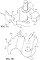
- FIGS. 3A through 3C illustrate a ratchet associated with a latch mechanism used in the one-motor power latch assembly shown in FIGS. 2A and 2B ;
- FIGS. 4A and 4B illustrate an alternative two-piece construction for the ratchet shown in FIGS. 3A through 3C ;
- FIGS. 5A and 5B illustrate the orientation and interaction of a pawl associated with the latch mechanism and a cinch lever associated with a latch cinch mechanism used in the one-motor power latch assembly shown in FIGS. 2A and 2B ;
- FIGS. 6A and 6B illustrate the orientation and interaction of a pawl lever and pawl lever biasing spring associated with the latch cinch mechanism used in the one-motor power latch assembly shown in FIGS. 2A and 2B ;
- FIGS. 7A through 7D illustrate the orientation and interaction of various components of a latch release mechanism and a power-operated actuation mechanism used in the one-motor power latch assembly shown in FIGS. 2A and 2B ;
- FIGS. 8A through 8C illustrate a series of sequential top elevational view showing the interaction and relative movement between various components of the one-motor power latch assembly upon movement of the closure panel from its open position into its closed position
- FIGS. 8D through 8F illustrate a similar series of sequential top elevational views showing the interaction and relative movement between various components of the one-motor power latch assembly upon movement of the closure panel from its closed position into its cinched closed position via operation of a power cinching feature provided in accordance with the present disclosure
- FIGS. 9A through 9F are a series of sequential bottom elevational views corresponding to FIGS. 8A through 8F and which further illustrate the power cinching feature;
- FIGS. 10A and 10B are top elevational views sequentially illustrating the interaction and relative movement between various components of the one-motor power latch assembly upon movement of the closure panel from its cinched closed position into its open position via operation of the power release feature which provides a soft opening function in accordance with the present disclosure;
- FIGS. 11A and 11B are bottom elevational views corresponding to FIGS. 10A and 10B and which further illustrate the power release feature of the present disclosure
- FIGS. 12A and 12B are additional views of various components of the latch mechanism when the closure panel is located in its closed position which show the lines of force acting thereon and also show a supplementary reinforcement mechanism provided by the one-motor power latch assembly of the present disclosure;
- FIG. 13 is a bottom elevational view of components of the latch mechanism and the cinch mechanism when the closure panel is located in its cinched closed position and showing the over-center ratchet retention configuration provided by the present disclosure
- FIGS. 14A and 14B are isometric views illustrating the interaction and orientation between various components of the latch mechanism and the cinch mechanism when the closure panel is located in its cinched closed position;
- FIGS. 15A through 15D illustrate the orientation and interaction of various components of the one-motor power latch assembly when the closure panel is located in its open position
- FIGS. 16A through 16D illustrate the orientation and interaction of various components of the one-motor power latch assembly when the closure panel is located in its closed position and immediately prior to initiation of the power cinching operation;
- FIGS. 17A through 17D illustrate the orientation and interaction of various components of the one-motor power latch assembly when the closure panel is located in its cinched closed position immediately following completion of the power cinching operation;
- FIGS. 18A through 18D illustrate the orientation and interaction of various components of the one-motor power latch assembly when the closure panel is located and maintained in its cinched closed position
- FIGS. 19A through 19D illustrate the orientation and interaction of various components of the one-motor power latch assembly following an uncinching and release operation provided by the power release feature of the present disclosure
- FIGS. 20A through 20D illustrate various components of the one-motor power latch assembly upon completion of the uncinching and release operation provided by the power release feature for permitting the closure panel to subsequently move to its open position;
- FIGS. 21A and 21B illustrate engagement of the pawl with a primary closing notch formed in the ratchet of the latch mechanism when the closure panel is located in its cinched closed position while FIGS. 21C and 21D correspondingly illustrate engagement of the pawl with a safety closing notch formed in the ratchet provided for locating and retaining the closure panel in a safety closed position;
- FIGS. 22A through 22C illustrate the orientation and interaction of various components associated with an inside release mechanism used with the one-motor power latch assembly shown in FIGS. 2A and 2B ;
- FIGS. 23A through 23C illustrate the orientation and interaction of various components associated with an outside release mechanism used with the one-motor power latch assembly
- FIGS. 24A through 24F illustrate the interaction between the actuator gear of the actuation mechanism and the release lever of the latch release mechanism upon rotation of the actuator gear between a Rest position and a Cinch position.
- Example embodiments will now be described more fully with reference to the accompanying drawings. To this end, the example embodiments are provided so that this disclosure will be thorough, and will fully convey its intended scope to those who are skilled in the art. Accordingly, numerous specific details are set forth such as examples of specific components, devices, and methods, to provide a thorough understanding of embodiments of the present disclosure. However, it will be apparent to those skilled in the art that specific details need not be employed, that example embodiments may be embodied in many different forms, and that neither should be construed to limit the scope of the present disclosure. In some example embodiments, well-known processes, well-known device structures, and well-known technologies are not described in detail.
- the expression “power latch assembly” will be used to generally indicate any power-operated latch device adapted for use with a vehicle closure panel to provide a power cinch feature in combination with a soft opening function with or without a power release feature.
- the expression “closure panel” will be used to indicate any element moveable between an open position and at least one closed position, respectively opening and closing an access to an inner compartment of a motor vehicle and therefore includes, without limitations, decklids, tailgates, liftgates, bonnet lids, and sunroofs in addition to the sliding or pivoting side passenger doors of a motor vehicle to which the following description will make explicit reference, purely by way of example.
- a motor vehicle 10 is shown to include a vehicle body 12 defining an opening 14 to an interior passenger compartment.
- a closure panel 16 is pivotably mounted to body 12 for movement between an open position (shown) and a fully closed position to respectively open and close opening 14 .
- a power latch assembly 18 is rigidly secured to closure panel 16 adjacent to an edge portion 16 A thereof and is releasably engageable with a striker 20 that is fixedly secured to a recessed edge portion 14 A of opening 14 .
- power latch assembly 18 is operable to engage striker 20 and releaseably move closure panel 16 into its fully closed position.
- An outside handle 22 and an inside handle 24 are provided for actuating power latch assembly 18 to release striker 20 and permit subsequent movement of closure panel 16 to its open position.
- An optional lock knob 26 is shown which provides a visual indication of the locked state of latch assembly 18 and which may also be operable to mechanically change the locked state of latch assembly 18 .
- a weather seal 28 is mounted on edge portion 14 A of opening 14 in vehicle body 12 and is adapted to be resiliently compressed upon engagement with a mating sealing surface of closure panel 16 when closure panel 16 is held by latch assembly 18 in its closed position so as to provide a sealed interface therebetween which is configured to prevent entry of rain and dirt into the passenger compartment while minimizing audible wind noise.
- the closure panel is hereinafter referred to as passenger door 16 .
- power latch assembly 500 is adapted for use with motor vehicle 10 shown in FIG. 1 and can be secured to closure panel 16 and operable to releaseably engage a striker 20 secured to edge portion 14 A of opening 14 in vehicle body 12 . It is also contemplated that power latch assembly 500 can be used in association with any type of latch control system.
- FIGS. 2A and 2B illustrate power latch assembly 500 to generally include a multi-piece structural framework and housing arrangement comprised of a rigid frame plate 502 , a latch housing 504 , a controller enclosure 506 , a motor housing 507 , and motor end cap 508 .
- the operational components of power latch assembly 500 are enclosed and/or mounted to one or more of these structural/housing components and will be described hereinafter to generally include a latch mechanism 510 , a latch cinch mechanism 512 , a latch release mechanism 514 , an actuation mechanism 516 , an inside latch release mechanism 518 , and an outside latch release mechanism 520 . These mechanisms interact to establish a plurality of distinct operative modes for power latch assembly 500 .
- a “released” mode is established when door 16 is located in an open position
- a “latched” mode is established when door 16 is located in a closed position
- a “cinched” mode is established when door 16 is located in a cinched closed position following operation of the power cinching feature.
- Power latch assembly 500 is further operable to establish an “uncinched/released” mode as part of an uncinching/soft opening function provided by the power release feature which facilitates movement of door 16 from its cinched closed position to a released position.
- Frame plate 502 is a rigid component configured to be fixedly secured to edge portion 16 A of door 16 and defines an entry aperture 524 through which striker 20 travels upon movement of door 16 toward and way from its closed position relative to vehicle body 12 .
- Latch mechanism 510 is shown, in this non-limiting example, as a single pawl arrangement including a ratchet 526 and a pawl 528 .
- Ratchet 526 is supported for pivotal movement on a ratchet pivot pin 530 that is fixed to frame plate 502 .
- Ratchet 526 is configured to include a contoured striker guide channel 532 which terminates in a striker capture pocket 534 , a primary closing notch 536 , a safety closing notch 538 , and a raised projection 540 defining a non-closing profile surface 542 .
- a two-piece ratchet assembly 527 is shown in FIGS. 4A and 4B to include a ratchet 526 ′ and a profile plate 529 that are attached via a link connector 531 , such as the tab and groove arrangement shown.
- Profile plate 529 has raised projection 540 ′ and its profile surface 542 ′ formed thereon.
- a ratchet biasing member shown schematically by arrow 544 (See FIG. 18A ), is adapted to normally bias ratchet 526 to rotate about pivot pin 530 in a first or releasing direction so as to permit striker 20 to be released from retention within striker capture pocket 534 and allow movement of door 16 from its released position toward its open position.
- ratchet 526 can be rotated in a second or latching direction, in opposition to the biasing of ratchet biasing member 544 , to permit latch mechanism 510 to retain striker 20 in striker capture pocket 534 and hold door 16 in one of its closed positions.
- Ratchet 526 can be rotated between a plurality of distinct ratchet positions including a first or “striker release” position, a second or “primary striker capture” position, and a third or “cinched striker capture” position.
- a fourth or “uncinched striker capture” position for ratchet 526 is also provided and is located between the primary and cinched striker capture positions.
- the striker release position of ratchet 526 is established when striker 20 is released from guide channel 532 .
- the primary striker capture position of ratchet 526 is established upon closure and initial mechanical latching of door 16 in its closed position.
- the cinched striker capture position of ratchet 526 is established upon completion of the power cinching operation for moving door 16 into its cinched closed position. Finally, the uncinched striker capture position is established by the power releasing operation for allowing door 16 to move from its cinched closed position to its released position.
- Pawl 528 is best shown in FIGS. 5A and 5B to be configured as an elongated component having a first end segment 528 a that is pivotably fixed via a pawl pivot pin 550 to a first end segment 552 a of a cinch lever 552 associated with latch cinch mechanism 512 .
- a pawl follower pin 554 extends outwardly from a second end segment 528 b of pawl 528 .
- Second end segment 528 b of pawl 528 also defines an engagement projection or flange 556 configured to selectively engage primary closing notch 536 on ratchet 526 when pawl 528 is located in a first or “ratchet checking” position after ratchet 526 has been forcibly rotated to its primary striker capture position via engagement with striker 20 .
- Cinch lever 552 is further shown to be supported for pivotal movement about a cinch lever pivot pin 560 which, in turn, is fixedly secured via a rivet portion 560 a to frame plate 502 .
- a gear link drive pin 562 extends outwardly from a second end segment 552 b of cinch lever 552 .
- pawl 528 is pivotably moveable with respect to ratchet 526 between its ratchet checking position and a second or “ratchet release” position whereat its engagement flange 556 is disengaged from primary closing notch 536 on ratchet 526 .
- pawl 528 is also adapted to translate between a first or “cinch start” pawl position and a second or “cinch stop” pawl position in response to pivotal movement of cinch lever 552 about pivot pin 560 caused by the power cinching operation.
- pivot post 550 establishes a “moveable” pawl axis which permits both pivotal and translational movement of pawl 528 relative to ratchet 526 .
- Pawl lever 566 is configured to include a cylindrical boss segment 570 and an elongated lever segment 572 .
- Boss segment 570 is rigidly fixed via a rivet pin or pivot post 574 to frame plate 502 to establish a fixed pivot axis for pawl lever 566 .
- pawl lever 566 is pivotable relative to ratchet 526 between a first or “Open” pawl lever position and a second or “Closed” pawl lever position.
- Lever segment 572 is configured to include an elongated guide slot 576 within which pawl follower pin 554 is slidingly retained.
- a pair of engagement lugs 578 and 580 extend from opposite sides of lever segment 572 .
- One end of closing spring 568 engages a fixed portion of frame plate 502 and the other end of closing spring 568 engages lug 580 on lever segment 572 of pawl lever 566 .
- closing spring 568 applies a directed biasing load on pawl lever 566 for normally biasing pawl lever 566 toward its Closed pawl lever position.
- closing spring 568 Due to retention of pawl follower pin 554 within contoured guide slot 576 , closing spring 568 also applies a directed biasing load on pawl 528 for normally biasing pawl 528 toward its ratchet checking position. As an alternative, closing spring 568 could act on pawl 528 for providing the same type of coordinated biasing arrangement.
- Lever segment 572 of pawl lever 566 is also configured to include a cam projection 582 that is adapted to selectively engage and disengage profiled surface 542 formed on raised projection 540 of ratchet 526 , based on the rotated position of ratchet 526 , thereby facilitating pivotal movement of pawl lever 566 about pivot post 574 .
- actuation mechanism 516 is shown to include an actuator gear 590 having a tubular boss segment 592 rotatably mounted on cinch lever pivot pin 560 .
- Actuator gear 590 also includes a gear segment 594 having a drive aperture 596 within which gear link drive pin 562 is retained.
- gear link drive pin 562 is fixed to second end segment 552 b of cinch lever 552 . Based on this arrangement, actuator gear 590 and cinch lever 552 are coupled for common rotation about pivot point 560 .
- Gear segment 594 of actuator gear 590 includes gear teeth 598 that are meshed, in this non-limiting example, with threads of a worm gear 600 .
- a power-operated device such as an electric motor 602 , has a rotary output component configured to drive a first stage reduction gearset 604 which, in turn, drives a second stage reduction gearset 606 .
- First stage gearset 604 includes a first worm gear 605 fixed for rotation with the rotary output of electric motor 602 and which is in constant mesh with a transfer gear 607 fixed for rotation with a drive shaft 609 . As best seen from FIG. 2B , the rotary output of electric motor 602 is aligned to extend transversely to driveshaft 609 .
- Second stage gearset 606 includes second worm gear 600 that is fixed for rotation with drive shaft 609 and, as noted, in constant mesh with gear teeth 598 on activator gear 590 .
- This dual-stage double-worm arrangement provides a compact gear arrangement and, in the non-limiting configuration shown, provides a “square” or 90° orientation between the motor shaft and activator gear 590 .
- bi-directional control of the rotation of the motor output component results in controlled bi-directional rotation of actuator gear 590 in concert with pivotal movement of cinch lever 552 about pivot axis 560 .
- Latch release mechanism 514 is best shown in FIGS. 7A-7D to include a pivotal release lever 610 and a release lever biasing spring 612 .
- Release lever 610 is pivotable about a release lever pivot post 614 that is rigidly secured to frame plate 502 .
- Release lever 610 is configured to include a first projection 616 adapted to engage a bent or “toggle” segment 618 of release lever biasing spring 612 , a second projection 620 engageable with one or more profiled segments of actuator gear 590 , and a third projection 622 engageable with engagement lug 580 on pawl lever 566 .
- the profiled segments formed on actuator gear 590 may include a release segment 624 and a reset segment 626 , the function of which will be detailed hereinafter.
- release lever biasing spring 612 is configured as a toggle spring to positively locate release lever 610 in one of three distinct release lever positions.
- FIGS. 8A, 9A, and 15A-15D illustrate power latch assembly 500 in its released mode with ratchet 526 located in its striker release position and ready to receive striker 20 as it enters through entry aperture 524 of frame plate 502 upon door 16 moving toward its closed position.
- FIGS. 566 also illustrate pawl lever 566 located in its Open pawl lever position such that its cam projection 582 is in engagement with profiled surface 542 formed on raised projection 540 of ratchet 526 .
- follower pin 554 on pawl 528 is positioned in proximity to a first terminal end of guide slot 576 .
- Actuator gear 590 is shown positioned in a first or “Rest” position. Since cinch lever 552 is pinned to rotate in concert with actuator gear 590 , cinch lever 552 is also shown pivoted about pivot axis 560 to a first or “uncinched” position.
- FIG. 9A also illustrates cinch lever 552 abutting or in close proximity to a first mechanical stop 630 when cinch lever 552 is located in its uncinched position. While not specifically shown, a first position sensor can be provided for detecting when actuator gear 590 is located in its Rest position and for providing a position signal indicative of this positioning to the latch control system.
- FIGS. 8B and 9B illustrate that engagement of striker 20 with guide channel 532 (caused by closure of door 16 ) has caused initial rotation of ratchet 526 in the latching direction. It will be noted that these illustrations indicate that pawl lever 566 is still located in its Open pawl lever position with its cam projection 582 maintained in contact with ratchet profile surface 542 so as to mechanically hold pawl 528 in its ratchet release position and its cinch start pawl position.
- pawl lever cam projection 582 disengages (i.e., falls off) profiled surface 542 on raised ratchet projection 540 while cinch lever 552 and actuator gear 590 are maintained in their respective uncinched and Rest positions so as to cause pawl lever 566 to pivot about pivot axis 574 with closing spring 568 forcibly pivoting pawl lever 566 from its Open pawl lever position to its Closed pawl lever position.
- This pivotal movement of pawl lever 566 causes pawl 528 to pivot about pivot axis 550 from its ratchet release position into its ratchet checking position due to retention of pawl follower pin 554 within guide slot 574 .
- pawl 526 is still positioned in its cinch start position.
- engagement flange 556 moves into contact with primary closing notch 536 on ratchet 526 , thereby establishing the latched mode of power latch assembly 500 .
- This latched mode is established mechanically via closing of door 16 to its closed position for locating ratchet 526 in its primary striker capture position.
- FIGS. 8C, 9C and 16A-16D illustrate initiation of the power cinching operation once ratchet 526 is retained in its primary striker capture position.
- Arrow 634 indicates the direction of rotation of actuator gear 590 in a first or “cinching” direction from its Rest position toward a second or “Cinch” position caused by energization of electric motor 602 .
- Such initial rotation of actuator gear 590 in the cinching direction causes concurrent rotation of cinch lever 552 about pivot axis 560 from its uncinched position toward a second or “cinched” position which, in turn, causes pawl 528 to also move with respect to pivot axis 550 .
- pawl follower pin 554 moves within guide slot 576 in pawl lever 566 as pawl lever 566 is maintained in its Closed pawl lever position.
- the contour of guide slot 576 is configured to move pawl 528 along a path coordinated with the continued rotation of ratchet 526 .
- pawl 528 acts as a “drive link” with respect to ratchet 526 such that its engagement flange 556 continues to engage primary closing notch 536 and forcibly rotate ratchet 526 in the latching direction from its primary striker capture position toward its cinched striker capture position, as indicated by Arrow 636 .
- FIGS. 8D-8F, 9D-9F and 17A-17D illustrate continued driven rotation of actuator gear 590 in the cinching direction until it reaches its Cinch position which, in turn, locates cinch lever 552 in its cinched position.
- Such movement of cinch lever 552 to it cinched position acts to move pawl 528 into its cinch stop pawl position which, in turn, moves ratchet 526 into its cinched striker capture position.
- cinch lever 552 engages a second mechanical stop 638 , as best shown in FIG. 9F , and the power cinching operation is completed.
- pawl follower pin 554 is now located in close proximity to a second terminal end of guide slot 576 .
- the arcuate contour of guide slot 576 is configured to ensure that engagement flange 556 on pawl 528 maintains continued engagement with primary closing notch 536 on ratchet 526 as pawl 528 forcibly rotates ratchet 526 into its cinched striker capture position.
- a second position sensor can be provided for detecting when actuator gear 590 is located in its Cinch position and for providing such a position signal to the latch control system.
- FIGS. 9F, 17A, and 17B show a directional force line, indicated by reference numeral 640 , which clearly illustrates an “over-center” retention arrangement established between the pawl/ratchet point of contact, pawl pivot point 550 and pivot axis 560 of actuator gear 590 when pawl 526 is located in its cinch stop pawl position, whereby no back drive of actuator gear 590 and the power-operated cinch actuator occurs.
- power latch assembly 500 also provides a power release feature that is configured to initially provide an uncinching function prior to release of ratchet 526 so as to provide a “soft open” of door 16 that is intended to eliminate or significantly reduce the “pop-off” noise associated with abrupt release of the compressed door seals. Accordingly, prior to initiation of the power release operation, the components of power latch assembly 500 are oriented and located as shown in FIGS. 8F, 9F and 18A-18D .
- ratchet 526 is held in its cinched striker capture position by pawl 528 located in its ratchet checking position and its cinch stop position, pawl lever 566 is located in its Closed pawl lever position, actuator gear 590 is located in its Cinch position, and cinch lever 552 is located in its cinched positions.
- motor 602 is energized to rotate actuator gear 590 in a second or “releasing” direction from its Cinch position back to its Rest position. Initial rotation of actuator gear 590 in this releasing direction is shown in FIGS. 10A and 11A and indicated by Arrow 646 .
- actuator gear 590 causes cinch lever 552 to pivot about axis 560 which, in turn, causes pivotal movement of pawl 528 about axis 550 and sliding movement of follower pin 554 within guide slot 476 while pawl lever 566 is held by closing spring 568 in its Closed pawl lever position.
- ratchet 526 is permitted to rotate in its releasing direction from its cinched striker capture position toward its uncinched striker capture position.
- engagement flange 556 on pawl 528 is maintained in contact with primary closing notch 536 during this initial limited range of “uncinching” rotation of ratchet 526 .
- initial engagement of release segment 624 on actuator gear 590 with second projection 620 on release lever 610 which is shown in its first or Rest position.
- FIGS. 19A-19D illustrate the “release point” established when ratchet 526 is rotated to its uncinched striker capture position.
- continued rotation of actuator gear 590 in the releasing direction causes release lever 610 to pivot about axis 614 from its Rest position into a second or Release position due to release segment 624 on actuator gear 590 engaging second projection 620 on release lever 610 .
- Such rotation of release lever 610 from its Rest position to its Release position causes third projection 622 on release lever 610 to engage lug 580 on pawl lever 556 and forcibly pivot pawl lever 556 about pivot point 574 , in opposition to the biasing of closing spring 568 , from its Closed pawl lever position to a Release/Open pawl lever position.
- pawl lever 566 With pawl lever 566 located in its Release/Open pawl lever position, the interaction between pawl follower pin 554 and guide slot 576 causes pawl 528 to be forcibly pivoted from its ratchet checking position into its ratchet release position such that engagement flange 556 on pawl 528 is now disengaged from primary closing notch 536 on ratchet 526 . Thereafter, ratchet 526 is permitted to rotate from its uncinched striker capture position to its striker release position shown in FIGS. 10B, 11B and FIGS. 20A-20D . Following release of ratchet 526 , actuator gear 590 continues to rotate back to its Rest position in preparation for the next door closing operation.
- power latch assembly 500 is shown to further include a supplemental structural component, such as a structural rivet 680 , that is fixedly secured to frame plate 502 and which is positioned to assist in containing deformation of pawl 528 during a crash incident occurring when door 16 is initially latched in its closed position (prior to power cinching) with ratchet 526 being held by pawl 528 in its primary striker capture position.
- a supplemental structural component such as a structural rivet 680 , that is fixedly secured to frame plate 502 and which is positioned to assist in containing deformation of pawl 528 during a crash incident occurring when door 16 is initially latched in its closed position (prior to power cinching) with ratchet 526 being held by pawl 528 in its primary striker capture position.
- the direction of anticipate loads exerted by striker 20 on ratchet 526 during such a crash incident are indicated by Arrow 682 ( FIG. 12A ).
- FIG. 13 illustrates, via line of force 640 , that cinch lever rivet 560 acts to resist deformation of pawl 526 when ratchet 526 is located in its cinched striker capture position following completion of the power cinching operation.
- FIGS. 14A and 14B also indicate installation of a cylindrical bushing 690 on cinch lever pivot post 560 . The function of bushing 690 is to maintain the distance between frame plate 502 and cinch lever 552 , contain deformation of cinch mechanism 512 during a collision situation, and rotate with pawl 528 in order to avoid friction during normal operation.
- Power latch assembly 500 is constructed and operable to rely on and utilize a single closing notch, namely primary closing notch 536 , to hold and move ratchet 526 from its primary striker capture position into its cinched striker capture position during the power cinching operation as well as to move ratchet 526 from its cinched striker capture position into its uncinched striker capture position during the power releasing operation.
- ratchet 526 is also provided with a safety closing notch 538 which is located to be engaged by engagement flange 556 of pawl 528 in its ratchet checking position in the event that an unintended disengagement between engagement flange 556 and primary closing notch 536 occurs.
- This secondary latching configuration is best shown in FIGS.
- FIGS. 21A through 21D show a safety striker capture position (shown in FIGS. 21C, 21D ).
- this additional safety latching provision will only provide a failsafe latching function as safety closing notch 538 is not used to provide any type of primary latching functions.
- Power latch assembly 500 is distinguished by use of a single closing notch (primary closing notch 536 ) and the use of pawl 528 (instead of a distinct cinch link lever) to mechanically hold ratchet 528 in its primary striker capture and cinched striker capture positions.
- inside latch release mechanism 518 is shown to include a pivotal release lever or handle 212 and a pivotal inside release link 700 that is pivotal about an axis 702 .
- Inside release link 700 has a tabbed first end segment 704 selectively engageable with pivotal handle 212 and a second end segment 706 arranged to selectively engage lug 578 on pawl lever 566 .
- Upward lifting movement of handle 212 as indicated by arrow 708 , associated with actuation of inside door handle 24 causes a drive end segment of handle 212 to engage first end segment 704 and cause pivotal movement of release link 700 about axis 702 from a “non-actuated” position ( FIG.
- FIGS. 22B and 22C illustrate an “actuated” position
- release link 700 With release link 700 in its non-actuated position, second end segment 706 does not engage and/or interfere with engagement of pawl 528 with ratchet 526 .
- FIG. 22B illustrates that movement of release link 700 to its actuated position causes its second end segment 706 to forcibly act on lug 578 and cause pawl lever 566 to pivot about its axis 574 to its Release/Open pawl lever position where engagement flange 556 on pawl 528 is disengaged from primary closing notch 536 on ratchet 526 , thereby permitting ratchet 526 to subsequently rotate to its released position.
- FIG. 22B illustrates the release of ratchet 526 from its cinch striker capture position (post-cinch).
- the arrangement shown in FIG. 22C is virtually identical to that shown in FIG. 22B except that release link 700 is releasing ratchet 526 from its primary striker capture position (pre-cinch).
- FIGS. 23A through 23C illustrate the components associated with outside latch release mechanism 520 .
- Outside release mechanism 520 is interactively associated with inside release mechanism 518 , and particularly, with inside release link 700 for moving it between the non-actuated ( FIG. 23A ) position and the non-actuated ( FIGS. 23B and 23C ) position.
- Outside release mechanism 520 includes an outside release link 720 that is supported for pivotal movement about a fixed pivot post 722 .
- Outside release link 720 includes a first end segment 724 positioned in engagement with an intermediate segment 703 of inside release link 700 , and a second end segment 726 acted upon via cable 728 for causing movement along a direction indicated by line 730 in response to actuation of outside door handle 22 .
- FIG. 23A through 23C illustrate the components associated with outside latch release mechanism 520 .
- Outside release mechanism 520 is interactively associated with inside release mechanism 518 , and particularly, with inside release link 700 for moving it between the non-actuated ( FIG. 23A ) position
- outside release link 720 is shown in a non-actuated position so as to maintain inside release link 700 in its non-actuated position.
- FIG. 23B illustrates outside release link 720 moved to an actuated position such that its first end segment 726 forcibly acts on intermediate segment 703 and pivots inside release link 700 to its actuated position, whereby inside release link 700 moves pawl lever 566 to its Release/Open pawl lever position for releasing pawl engagement flange 556 from engagement with primary closing notch 536 on ratchet 526 .
- FIG. 23B illustrates release of ratchet 526 from its cinched striker capture position (post-cinch) while FIG.
- 23C illustrates release of ratchet 526 from its primary striker capture position (pre-cinch). While not specifically shown, one or both of inside release link 700 and outside release link 720 can be biased by a suitable return spring to normally be located in its/their non-actuated position.
- FIG. 24A shows release lever 610 in its middle or Rest position that is established when actuator gear 590 is located in its Cinch position. This middle position is defined and established by the interaction of release lever biasing spring 612 acting on release lever projection 616 and closing spring 568 acting to bias lug 580 on pawl lever 566 into engagement with release lever projection 622 .
- FIG. 24A shows release lever 610 in its middle or Rest position that is established when actuator gear 590 is located in its Cinch position. This middle position is defined and established by the interaction of release lever biasing spring 612 acting on release lever projection 616 and closing spring 568 acting to bias lug 580 on pawl lever 566 into engagement with release lever projection 622 .
- FIG. 24A shows release lever 610 in its middle or Rest position that is established when actuator gear 590 is located in its Cinch position. This middle position is defined and established by the interaction of release lever biasing spring 612 acting on release lever projection 616 and closing spring 568 acting to bias lug 580 on pawl lever 566 into engagement with release lever
- FIGS. 24C and 24E illustrate that rotation of actuator gear 590 from its Rest position toward its Cinch position during the power cinching operation with release lever 610 located in a Safety position.
- the Safety position is configured to prevent unintended release of ratchet (via actuation of release lever 610 ) in the event of motor failure during the power cinching operation.
- FIG. 24F illustrates that second gear segment 626 functions to move release lever 610 from its Safety position back into its Rest position upon completion of the power cinching operation.
- the power latch assembly described above is adapted to overcome acknowledged shortcomings of conventional power latch devices including the elimination of the audible “pop” sound generated upon quick release of the seal loads and use of the cinch actuator to always assist in completing the door closing function independently of the closing energy applied to the door.
- the cinch actuator associated with the power latch assembly of the present disclosure is configured to drive the ratchet slowly in a release direction from its cinched striker capture position to its uncinched striker capture position to provide a predetermined amount of striker travel selected to significantly reduce the seal load prior to complete release of the ratchet.
- a latch control system having a controller and various sensors configured to provide input signals to the controller that are used to control coordinated control of electric motor 602 in one-motor version of power latch assembly and 500 .
Landscapes
- Lock And Its Accessories (AREA)
Abstract
Description
Claims (21)
Priority Applications (1)
| Application Number | Priority Date | Filing Date | Title |
|---|---|---|---|
| US15/276,926 US11162284B2 (en) | 2015-09-29 | 2016-09-27 | One motor latch assembly with power cinch and power release having soft opening function |
Applications Claiming Priority (2)
| Application Number | Priority Date | Filing Date | Title |
|---|---|---|---|
| US201562234260P | 2015-09-29 | 2015-09-29 | |
| US15/276,926 US11162284B2 (en) | 2015-09-29 | 2016-09-27 | One motor latch assembly with power cinch and power release having soft opening function |
Publications (2)
| Publication Number | Publication Date |
|---|---|
| US20170089103A1 US20170089103A1 (en) | 2017-03-30 |
| US11162284B2 true US11162284B2 (en) | 2021-11-02 |
Family
ID=58282118
Family Applications (1)
| Application Number | Title | Priority Date | Filing Date |
|---|---|---|---|
| US15/276,926 Active 2039-12-31 US11162284B2 (en) | 2015-09-29 | 2016-09-27 | One motor latch assembly with power cinch and power release having soft opening function |
Country Status (3)
| Country | Link |
|---|---|
| US (1) | US11162284B2 (en) |
| CN (1) | CN107023228B (en) |
| DE (1) | DE102016218299A1 (en) |
Cited By (5)
| Publication number | Priority date | Publication date | Assignee | Title |
|---|---|---|---|---|
| US20220178178A1 (en) * | 2019-04-17 | 2022-06-09 | Magna Closures Inc. | Closure latch assembly with power reset circuit mechanism and method for reset |
| US11371267B2 (en) * | 2015-12-22 | 2022-06-28 | Kiekert Ag | Motor vehicle lock with rotary latch support |
| US12054972B2 (en) | 2021-02-12 | 2024-08-06 | Magna Closures Inc. | Closure latch assembly with cinch mechanism and variable powered anti-pinch cinch control |
| US20250179839A1 (en) * | 2022-03-30 | 2025-06-05 | Kiekert Aktiengesellschaft | Motor vehicle lock device |
| US12345077B2 (en) | 2021-05-26 | 2025-07-01 | Magna Closures Inc. | Closure latch assembly equipped with a power cinch mechanism having a cinch pawl |
Families Citing this family (32)
| Publication number | Priority date | Publication date | Assignee | Title |
|---|---|---|---|---|
| DE102014005656A1 (en) * | 2014-04-17 | 2015-10-22 | Kiekert Aktiengesellschaft | Drive unit for securing a rotational axis distance of gear elements |
| US10555425B2 (en) * | 2016-02-18 | 2020-02-04 | Magna Closures Inc. | Enclosure assembly for an electronic controller having an over-molded part to protect electronic components |
| US10895095B2 (en) | 2016-10-06 | 2021-01-19 | Magna Closures S.P.A. | Power closure latch assembly with cinch mechanism having ratchet retention function |
| US11072948B2 (en) * | 2016-12-14 | 2021-07-27 | Magna Closures S.P.A. | Smart latch |
| DE102017105657A1 (en) * | 2017-03-16 | 2018-09-20 | Kiekert Ag | ACTUATOR FOR MOTOR VEHICLE APPLICATIONS |
| US11525289B2 (en) | 2017-07-17 | 2022-12-13 | Magna Closures Inc. | Vehicular closure latch assembly with roller-type latch mechanism and cinch mechanism |
| US11859416B2 (en) | 2017-11-15 | 2024-01-02 | Magna BOCO GmbH | Latch assembly with power release and dual stage cinch function |
| US10711503B2 (en) | 2017-11-15 | 2020-07-14 | Ford Global Technologies, Llc | Door presenter, cinch and edge guard actuator |
| JP6884094B2 (en) * | 2017-12-25 | 2021-06-09 | 三井金属アクト株式会社 | Vehicle door latch device |
| US11608664B2 (en) | 2017-12-25 | 2023-03-21 | Mitsui Kinzoku Act Corporation | Vehicle door latch apparatus |
| KR102602981B1 (en) * | 2018-02-14 | 2023-11-16 | 현대자동차주식회사 | Apparatus for hood latch of vehicle |
| DE102019104713A1 (en) | 2018-02-27 | 2019-08-29 | Magna Closures Inc. | Powered latch assembly with impact protection |
| US20190301212A1 (en) * | 2018-03-27 | 2019-10-03 | Magna BOCO GmbH | Closure latch assembly with latch mechanism having a dual-pawl configuration |
| US11180934B2 (en) * | 2018-07-23 | 2021-11-23 | Inteva Products, Llc | Cinch override mechanism for latch assembly |
| US12281502B2 (en) | 2018-09-12 | 2025-04-22 | Magna Closures Inc. | Load equalizer for latches of closure panels in motor vehicles |
| US11512510B2 (en) * | 2018-10-03 | 2022-11-29 | Magna Closures Inc. | Closure latch assembly for vehicle door panels having a latch mechanism with enhanced pawl configuration |
| DE102018125208A1 (en) * | 2018-10-11 | 2020-04-16 | Brose Schließsysteme GmbH & Co. Kommanditgesellschaft | Procedure for operating an opening mechanism |
| DE102019123837A1 (en) * | 2018-10-22 | 2020-04-23 | Kiekert Aktiengesellschaft | Motor vehicle lock |
| DE102019134659A1 (en) * | 2018-12-18 | 2020-06-18 | Magna Closures Inc. | INTELLIGENT LOCKING DEVICE WITH DOUBLE-LOCK LOCKING MECHANISM WITH FLEXIBLE CONNECTION TO A RELEASE MECHANISM |
| US20200224464A1 (en) * | 2019-01-10 | 2020-07-16 | Magna Closures Inc. | Smart latch assembly with actuator module |
| US11585127B2 (en) * | 2019-07-01 | 2023-02-21 | Brose Schließsysteme GmbH & Co. Kommanditgesellschaft, Wuppertal | Motor vehicle lock |
| DE112020003279T5 (en) * | 2019-07-08 | 2022-04-21 | Magna Closures Inc. | Latch assembly with power operated tightening mechanism with anti-pinch function |
| US11739569B2 (en) | 2019-10-10 | 2023-08-29 | Magna Closures Inc. | System to isolate two motor driving circuits driving a single motor and method for isolation |
| DE102019128335A1 (en) * | 2019-10-21 | 2021-04-22 | Khs Corpoplast Gmbh | A clamp system comprising a clamp module carrier and a clamp module for holding workpieces |
| DE102021111208A1 (en) * | 2020-05-28 | 2021-12-02 | Magna Closures Inc. | Main and secondary locks for locks on motor vehicles |
| CN113756665B (en) | 2020-06-02 | 2023-02-17 | 麦格纳覆盖件有限公司 | Closure latch assembly and method of controlling operation of closure latch assembly |
| DE102020124905A1 (en) | 2020-09-24 | 2022-03-24 | Kiekert Aktiengesellschaft | Drive for automotive applications |
| US12241292B2 (en) | 2021-02-23 | 2025-03-04 | Magna Automotive Parts (Suzhou) Co., Ltd. | Lock device of a vehicle |
| CN112943010B (en) | 2021-04-08 | 2025-06-03 | 麦格纳汽车系统(苏州)有限公司 | Vehicle door lock capable of assisting door opening |
| DE102022116900A1 (en) | 2021-07-08 | 2023-01-12 | Magna Closures Inc. | Latch-latch assembly with power latch release mechanism with dual drive power release actuator and multi-stage gearing |
| US20250043599A1 (en) * | 2023-08-02 | 2025-02-06 | Kiekert Ag | Motor vehicle lock, in particular motor vehicle side door lock |
| DE102023126418A1 (en) * | 2023-09-28 | 2025-04-03 | Bos Gmbh & Co. Kg | Tailgate system for a motor vehicle |
Citations (49)
| Publication number | Priority date | Publication date | Assignee | Title |
|---|---|---|---|---|
| US4892339A (en) * | 1987-07-29 | 1990-01-09 | Kiekert Gmbh & Co. Kommanditgesellschaft | Power-closing motor-vehicle door latch |
| US5288115A (en) * | 1991-12-06 | 1994-02-22 | Mitsui Kinzoku Kogyo Kabushiki Kaisha | Auto-closing vehicle door lock device |
| US5423582A (en) * | 1993-04-09 | 1995-06-13 | Kiekert Gmbh & Co. Kg | Power-assist motor-vehicle door latch |
| US5433496A (en) * | 1993-04-09 | 1995-07-18 | Kiekert Gmbh & Co. Kg | Motor-vehicle door latch with power assist |
| US5639130A (en) * | 1995-05-31 | 1997-06-17 | General Motors Corporation | Rotary door cinching mechanism with manual override |
| US5769468A (en) * | 1995-08-18 | 1998-06-23 | Kiekert Ag | Power-assist motor-vehicle door latch |
| US5899508A (en) * | 1996-08-19 | 1999-05-04 | Atoma International Inc. | Double locking vehicle door latch |
| US5918917A (en) * | 1997-07-22 | 1999-07-06 | General Motors Corporation | Vehicle door latch with cinching mechanism |
| US5941579A (en) * | 1997-08-21 | 1999-08-24 | Atoma International Corp. | Vehicle door latch with reduced release effort |
| EP0978609A1 (en) | 1998-08-05 | 2000-02-09 | Valeo Securite Habitacle | Electric power assisted door lock |
| US6053542A (en) * | 1998-06-26 | 2000-04-25 | General Motors Corporation | Vehicle door latch with cinching mechanism |
| CA2382487A1 (en) * | 1999-09-13 | 2001-03-22 | Atoma International Corp. | A powered vehicle door latch and actuator therefor |
| US6341448B1 (en) * | 1997-08-13 | 2002-01-29 | Atoma International Corp. | Cinching latch |
| EP1176273A2 (en) | 2000-07-25 | 2002-01-30 | Meritor Light Vehicle Systems (UK) Ltd | Latch arrangement |
| US6439623B1 (en) * | 1999-02-04 | 2002-08-27 | Robert Bosch Gmbh | Door lock of a motor vehicle or the like with an electric locking aid and opening aid |
| US6540270B1 (en) * | 1999-11-20 | 2003-04-01 | Kiekert Ag | Power closer for motor-vehicle door latch |
| US6550825B2 (en) * | 2000-06-06 | 2003-04-22 | Delphi Technologies, Inc. | Cinching door latch with planetary release mechanism |
| US6557910B2 (en) * | 2000-11-27 | 2003-05-06 | Denso Corporation | Door lock drive unit |
| WO2003071064A1 (en) | 2002-02-25 | 2003-08-28 | Intier Automotive Closures Inc. | Latch having releasable cinching mechanism |
| US6764113B1 (en) * | 1999-09-13 | 2004-07-20 | Atoma International Corp. | Powered vehicle door latch and actuator therefor |
| US7175212B2 (en) * | 2002-02-25 | 2007-02-13 | Intier Automotive Closures Inc. | Latch having releasable cinching mechanism |
| US7261336B2 (en) * | 2004-07-15 | 2007-08-28 | Brose Schliessysteme Gmbh & Co. Kg | Motor vehicle lock |
| DE102013008415A1 (en) * | 2013-05-17 | 2014-11-20 | BROSE SCHLIEßSYSTEME GMBH & CO. KG | Motor vehicle lock |
| DE102014002580A1 (en) * | 2014-02-26 | 2015-08-27 | Kiekert Aktiengesellschaft | Closing device for a motor vehicle hood |
| DE202014103819U1 (en) * | 2014-08-18 | 2015-11-19 | BROSE SCHLIEßSYSTEME GMBH & CO. KG | Motor vehicle lock |
| US20160186468A1 (en) * | 2013-07-17 | 2016-06-30 | Magna Closures Inc. | Dual motor device with application to power cinch and latch mechanism |
| US20170089105A1 (en) | 2015-09-29 | 2017-03-30 | Magna Closures S.P.A. | Automotive latch with pulley for flexible cable routing |
| WO2018030556A2 (en) * | 2016-08-09 | 2018-02-15 | 평화정공 주식회사 | Latch device for vehicle trunk |
| US20180087298A1 (en) * | 2016-09-23 | 2018-03-29 | Strattec Security Corporation | Powered latch mechanism with manual release |
| US20180100331A1 (en) * | 2016-10-06 | 2018-04-12 | Magna Closures Inc. | Power closure latch assembly with cinch mechanism having ratchet retention function |
| US20180163439A1 (en) * | 2016-12-14 | 2018-06-14 | Magna Closures Inc. | Smart latch |
| US20180171679A1 (en) * | 2016-12-19 | 2018-06-21 | Hyundai Motor Company | Tailgate opening and closing device for vehicle |
| US20180171677A1 (en) * | 2016-12-19 | 2018-06-21 | Hyundai Motor Company | Tailgate opening and closing device for vehicle |
| US20180347239A1 (en) * | 2017-06-02 | 2018-12-06 | Hyundai Motor Company | Trunk lid latch assembly for vehicle |
| US20190017301A1 (en) * | 2017-07-17 | 2019-01-17 | Magna Closures Inc. | Vehicular closure latch assembly with roller-type latch mechanism and cinch mechanism |
| US20190063117A1 (en) * | 2017-08-28 | 2019-02-28 | Magna Closures Inc. | Spring assisted actuator for power release and/or cinching functionality |
| US10246911B2 (en) * | 2016-06-02 | 2019-04-02 | Albert Marasco | Recreational or utility vehicle door opening system |
| US10280653B2 (en) * | 2011-07-14 | 2019-05-07 | Inteva Products, Llc | Vehicle door latch with electronic override |
| US20190136590A1 (en) * | 2017-11-09 | 2019-05-09 | Magna Closures Inc. | Latch assembly for motor vehicle closure system having power release mechanism with mechanical release and reset feature |
| US20190145135A1 (en) * | 2017-11-15 | 2019-05-16 | Magna BOCO GmbH | Latch assembly with power release and dual stage cinch funtion |
| US10309130B2 (en) * | 2013-08-21 | 2019-06-04 | Kiekert Aktiengesellschaft | Motor vehicle door lock |
| US10329806B2 (en) * | 2014-01-31 | 2019-06-25 | Kiekert Ag | Closing device for a motor-vehicle hood, and method |
| US20190226247A1 (en) * | 2017-11-15 | 2019-07-25 | Magna BOCO GmbH | Latch assembly with power release and dual stage cinch function |
| US10378252B2 (en) * | 2015-02-25 | 2019-08-13 | Magna Closures S.P.A. | Dual motor latch assembly with power cinch and power release having soft opening function |
| US20190249467A1 (en) * | 2018-02-15 | 2019-08-15 | Magna Closures Inc. | Closure latch assembly for motor vehicle having common kinematic chain for power release mechanism and mechanical backup release mechanism |
| US20190271179A1 (en) * | 2018-03-01 | 2019-09-05 | Magna Closures Inc. | Closure latch assembly with is/os backup mechanism having integrated splitter box arrangement |
| US20190301212A1 (en) * | 2018-03-27 | 2019-10-03 | Magna BOCO GmbH | Closure latch assembly with latch mechanism having a dual-pawl configuration |
| US10472869B2 (en) * | 2015-03-12 | 2019-11-12 | Strattec Security Corporation | Powered latch mechanism with manual release |
| US20200024872A1 (en) * | 2018-07-23 | 2020-01-23 | Inteva Products, Llc | Cinch override mechanism for latch assembly |
Family Cites Families (6)
| Publication number | Priority date | Publication date | Assignee | Title |
|---|---|---|---|---|
| FR2916788B1 (en) * | 2007-06-01 | 2013-02-15 | Valeo Securite Habitacle | ELECTRIC LOCK WITH CLOSURE ASSIST FOR OPENING OF A MOTOR VEHICLE |
| DE102012101092A1 (en) * | 2012-02-10 | 2013-08-14 | Huf Hülsbeck & Fürst Gmbh & Co. Kg | lock assembly |
| JP5961896B2 (en) * | 2012-03-26 | 2016-08-03 | 三井金属アクト株式会社 | Door closer equipment |
| DE102012102724A1 (en) * | 2012-03-29 | 2013-10-02 | Huf Hülsbeck & Fürst Gmbh & Co. Kg | Motor vehicle door lock |
| WO2014000084A1 (en) * | 2012-06-25 | 2014-01-03 | Magna Closures Inc. | Vehicular latch with direct locking of pawl |
| DE102015000824A1 (en) * | 2014-01-23 | 2015-07-23 | Magna Closures Inc. | Door lock device for motor vehicles |
-
2016
- 2016-09-23 DE DE102016218299.4A patent/DE102016218299A1/en active Pending
- 2016-09-27 US US15/276,926 patent/US11162284B2/en active Active
- 2016-09-28 CN CN201610861032.XA patent/CN107023228B/en active Active
Patent Citations (49)
| Publication number | Priority date | Publication date | Assignee | Title |
|---|---|---|---|---|
| US4892339A (en) * | 1987-07-29 | 1990-01-09 | Kiekert Gmbh & Co. Kommanditgesellschaft | Power-closing motor-vehicle door latch |
| US5288115A (en) * | 1991-12-06 | 1994-02-22 | Mitsui Kinzoku Kogyo Kabushiki Kaisha | Auto-closing vehicle door lock device |
| US5423582A (en) * | 1993-04-09 | 1995-06-13 | Kiekert Gmbh & Co. Kg | Power-assist motor-vehicle door latch |
| US5433496A (en) * | 1993-04-09 | 1995-07-18 | Kiekert Gmbh & Co. Kg | Motor-vehicle door latch with power assist |
| US5639130A (en) * | 1995-05-31 | 1997-06-17 | General Motors Corporation | Rotary door cinching mechanism with manual override |
| US5769468A (en) * | 1995-08-18 | 1998-06-23 | Kiekert Ag | Power-assist motor-vehicle door latch |
| US5899508A (en) * | 1996-08-19 | 1999-05-04 | Atoma International Inc. | Double locking vehicle door latch |
| US5918917A (en) * | 1997-07-22 | 1999-07-06 | General Motors Corporation | Vehicle door latch with cinching mechanism |
| US6341448B1 (en) * | 1997-08-13 | 2002-01-29 | Atoma International Corp. | Cinching latch |
| US5941579A (en) * | 1997-08-21 | 1999-08-24 | Atoma International Corp. | Vehicle door latch with reduced release effort |
| US6053542A (en) * | 1998-06-26 | 2000-04-25 | General Motors Corporation | Vehicle door latch with cinching mechanism |
| EP0978609A1 (en) | 1998-08-05 | 2000-02-09 | Valeo Securite Habitacle | Electric power assisted door lock |
| US6439623B1 (en) * | 1999-02-04 | 2002-08-27 | Robert Bosch Gmbh | Door lock of a motor vehicle or the like with an electric locking aid and opening aid |
| US6764113B1 (en) * | 1999-09-13 | 2004-07-20 | Atoma International Corp. | Powered vehicle door latch and actuator therefor |
| CA2382487A1 (en) * | 1999-09-13 | 2001-03-22 | Atoma International Corp. | A powered vehicle door latch and actuator therefor |
| US6540270B1 (en) * | 1999-11-20 | 2003-04-01 | Kiekert Ag | Power closer for motor-vehicle door latch |
| US6550825B2 (en) * | 2000-06-06 | 2003-04-22 | Delphi Technologies, Inc. | Cinching door latch with planetary release mechanism |
| EP1176273A2 (en) | 2000-07-25 | 2002-01-30 | Meritor Light Vehicle Systems (UK) Ltd | Latch arrangement |
| US6557910B2 (en) * | 2000-11-27 | 2003-05-06 | Denso Corporation | Door lock drive unit |
| WO2003071064A1 (en) | 2002-02-25 | 2003-08-28 | Intier Automotive Closures Inc. | Latch having releasable cinching mechanism |
| US7175212B2 (en) * | 2002-02-25 | 2007-02-13 | Intier Automotive Closures Inc. | Latch having releasable cinching mechanism |
| US7261336B2 (en) * | 2004-07-15 | 2007-08-28 | Brose Schliessysteme Gmbh & Co. Kg | Motor vehicle lock |
| US10280653B2 (en) * | 2011-07-14 | 2019-05-07 | Inteva Products, Llc | Vehicle door latch with electronic override |
| DE102013008415A1 (en) * | 2013-05-17 | 2014-11-20 | BROSE SCHLIEßSYSTEME GMBH & CO. KG | Motor vehicle lock |
| US20160186468A1 (en) * | 2013-07-17 | 2016-06-30 | Magna Closures Inc. | Dual motor device with application to power cinch and latch mechanism |
| US10309130B2 (en) * | 2013-08-21 | 2019-06-04 | Kiekert Aktiengesellschaft | Motor vehicle door lock |
| US10329806B2 (en) * | 2014-01-31 | 2019-06-25 | Kiekert Ag | Closing device for a motor-vehicle hood, and method |
| DE102014002580A1 (en) * | 2014-02-26 | 2015-08-27 | Kiekert Aktiengesellschaft | Closing device for a motor vehicle hood |
| DE202014103819U1 (en) * | 2014-08-18 | 2015-11-19 | BROSE SCHLIEßSYSTEME GMBH & CO. KG | Motor vehicle lock |
| US10378252B2 (en) * | 2015-02-25 | 2019-08-13 | Magna Closures S.P.A. | Dual motor latch assembly with power cinch and power release having soft opening function |
| US10472869B2 (en) * | 2015-03-12 | 2019-11-12 | Strattec Security Corporation | Powered latch mechanism with manual release |
| US20170089105A1 (en) | 2015-09-29 | 2017-03-30 | Magna Closures S.P.A. | Automotive latch with pulley for flexible cable routing |
| US10246911B2 (en) * | 2016-06-02 | 2019-04-02 | Albert Marasco | Recreational or utility vehicle door opening system |
| WO2018030556A2 (en) * | 2016-08-09 | 2018-02-15 | 평화정공 주식회사 | Latch device for vehicle trunk |
| US20180087298A1 (en) * | 2016-09-23 | 2018-03-29 | Strattec Security Corporation | Powered latch mechanism with manual release |
| US20180100331A1 (en) * | 2016-10-06 | 2018-04-12 | Magna Closures Inc. | Power closure latch assembly with cinch mechanism having ratchet retention function |
| US20180163439A1 (en) * | 2016-12-14 | 2018-06-14 | Magna Closures Inc. | Smart latch |
| US20180171679A1 (en) * | 2016-12-19 | 2018-06-21 | Hyundai Motor Company | Tailgate opening and closing device for vehicle |
| US20180171677A1 (en) * | 2016-12-19 | 2018-06-21 | Hyundai Motor Company | Tailgate opening and closing device for vehicle |
| US20180347239A1 (en) * | 2017-06-02 | 2018-12-06 | Hyundai Motor Company | Trunk lid latch assembly for vehicle |
| US20190017301A1 (en) * | 2017-07-17 | 2019-01-17 | Magna Closures Inc. | Vehicular closure latch assembly with roller-type latch mechanism and cinch mechanism |
| US20190063117A1 (en) * | 2017-08-28 | 2019-02-28 | Magna Closures Inc. | Spring assisted actuator for power release and/or cinching functionality |
| US20190136590A1 (en) * | 2017-11-09 | 2019-05-09 | Magna Closures Inc. | Latch assembly for motor vehicle closure system having power release mechanism with mechanical release and reset feature |
| US20190145135A1 (en) * | 2017-11-15 | 2019-05-16 | Magna BOCO GmbH | Latch assembly with power release and dual stage cinch funtion |
| US20190226247A1 (en) * | 2017-11-15 | 2019-07-25 | Magna BOCO GmbH | Latch assembly with power release and dual stage cinch function |
| US20190249467A1 (en) * | 2018-02-15 | 2019-08-15 | Magna Closures Inc. | Closure latch assembly for motor vehicle having common kinematic chain for power release mechanism and mechanical backup release mechanism |
| US20190271179A1 (en) * | 2018-03-01 | 2019-09-05 | Magna Closures Inc. | Closure latch assembly with is/os backup mechanism having integrated splitter box arrangement |
| US20190301212A1 (en) * | 2018-03-27 | 2019-10-03 | Magna BOCO GmbH | Closure latch assembly with latch mechanism having a dual-pawl configuration |
| US20200024872A1 (en) * | 2018-07-23 | 2020-01-23 | Inteva Products, Llc | Cinch override mechanism for latch assembly |
Non-Patent Citations (2)
| Title |
|---|
| Machine Translation of DE 102013008415 A1, 2021, pp. 1-13 (Year: 2021). * |
| Machine Translation of DE 102014002580, 2020, pp. 1-15 (Year: 2020). * |
Cited By (6)
| Publication number | Priority date | Publication date | Assignee | Title |
|---|---|---|---|---|
| US11371267B2 (en) * | 2015-12-22 | 2022-06-28 | Kiekert Ag | Motor vehicle lock with rotary latch support |
| US20220178178A1 (en) * | 2019-04-17 | 2022-06-09 | Magna Closures Inc. | Closure latch assembly with power reset circuit mechanism and method for reset |
| US12084898B2 (en) * | 2019-04-17 | 2024-09-10 | Magna Closures Inc. | Closure latch assembly with power reset circuit mechanism and method for reset |
| US12054972B2 (en) | 2021-02-12 | 2024-08-06 | Magna Closures Inc. | Closure latch assembly with cinch mechanism and variable powered anti-pinch cinch control |
| US12345077B2 (en) | 2021-05-26 | 2025-07-01 | Magna Closures Inc. | Closure latch assembly equipped with a power cinch mechanism having a cinch pawl |
| US20250179839A1 (en) * | 2022-03-30 | 2025-06-05 | Kiekert Aktiengesellschaft | Motor vehicle lock device |
Also Published As
| Publication number | Publication date |
|---|---|
| US20170089103A1 (en) | 2017-03-30 |
| DE102016218299A1 (en) | 2017-03-30 |
| CN107023228A (en) | 2017-08-08 |
| CN107023228B (en) | 2019-12-20 |
Similar Documents
| Publication | Publication Date | Title |
|---|---|---|
| US11162284B2 (en) | One motor latch assembly with power cinch and power release having soft opening function | |
| US10767397B2 (en) | Single motor latch assembly with power cinch and power release having soft opening function | |
| US11525289B2 (en) | Vehicular closure latch assembly with roller-type latch mechanism and cinch mechanism | |
| US12291899B2 (en) | Latch assembly with power release and dual stage cinch function | |
| US10767396B2 (en) | Vehicular latch assembly with latch mechanism having pop-off sound reduction | |
| CN107916847B (en) | Power closed latch assembly including tie pull mechanism with ratchet retention | |
| CN110359787B (en) | Auto door latch with power open feature | |
| US11512504B2 (en) | Latch assembly with power release and dual stage cinch function | |
| US8336929B2 (en) | Double latch assembly for a motor vehicle | |
| US20200115932A1 (en) | Single motor latch assembly with power cinch and power release having soft opening function | |
| CN110306887B (en) | Closure latch assembly with latch mechanism in dual pawl configuration | |
| US10214945B2 (en) | Door latch assembly for motor vehicles | |
| US11421451B2 (en) | Closure latch assembly for motor vehicle having common kinematic chain for power release mechanism and mechanical backup release mechanism | |
| US20190063117A1 (en) | Spring assisted actuator for power release and/or cinching functionality | |
| US10745948B2 (en) | Vehicular closure latch assembly having double pawl latch mechanism | |
| US12345077B2 (en) | Closure latch assembly equipped with a power cinch mechanism having a cinch pawl | |
| US12054972B2 (en) | Closure latch assembly with cinch mechanism and variable powered anti-pinch cinch control |
Legal Events
| Date | Code | Title | Description |
|---|---|---|---|
| AS | Assignment |
Owner name: MAGNA CLOSURES S.P.A., ITALY Free format text: ASSIGNMENT OF ASSIGNORS INTEREST;ASSIGNORS:OTTINO, FRANCO GIOVANNI;CUMBO, FRANCESCO;TAURASI, MARCO;AND OTHERS;REEL/FRAME:040569/0281 Effective date: 20151005 |
|
| STPP | Information on status: patent application and granting procedure in general |
Free format text: DOCKETED NEW CASE - READY FOR EXAMINATION |
|
| STPP | Information on status: patent application and granting procedure in general |
Free format text: NON FINAL ACTION MAILED |
|
| STPP | Information on status: patent application and granting procedure in general |
Free format text: RESPONSE TO NON-FINAL OFFICE ACTION ENTERED AND FORWARDED TO EXAMINER |
|
| STPP | Information on status: patent application and granting procedure in general |
Free format text: FINAL REJECTION MAILED |
|
| STPP | Information on status: patent application and granting procedure in general |
Free format text: RESPONSE AFTER FINAL ACTION FORWARDED TO EXAMINER |
|
| STPP | Information on status: patent application and granting procedure in general |
Free format text: NOTICE OF ALLOWANCE MAILED -- APPLICATION RECEIVED IN OFFICE OF PUBLICATIONS |
|
| STPP | Information on status: patent application and granting procedure in general |
Free format text: PUBLICATIONS -- ISSUE FEE PAYMENT VERIFIED |
|
| STCF | Information on status: patent grant |
Free format text: PATENTED CASE |
|
| MAFP | Maintenance fee payment |
Free format text: PAYMENT OF MAINTENANCE FEE, 4TH YEAR, LARGE ENTITY (ORIGINAL EVENT CODE: M1551); ENTITY STATUS OF PATENT OWNER: LARGE ENTITY Year of fee payment: 4 |