US11147082B2 - Radio base station, central apparatus, and distributed apparatus - Google Patents
Radio base station, central apparatus, and distributed apparatus Download PDFInfo
- Publication number
- US11147082B2 US11147082B2 US16/184,171 US201816184171A US11147082B2 US 11147082 B2 US11147082 B2 US 11147082B2 US 201816184171 A US201816184171 A US 201816184171A US 11147082 B2 US11147082 B2 US 11147082B2
- Authority
- US
- United States
- Prior art keywords
- scheduling process
- radio communication
- base station
- radio
- processor
- Prior art date
- Legal status (The legal status is an assumption and is not a legal conclusion. Google has not performed a legal analysis and makes no representation as to the accuracy of the status listed.)
- Active
Links
Images


Classifications
-
- H—ELECTRICITY
- H04—ELECTRIC COMMUNICATION TECHNIQUE
- H04W—WIRELESS COMMUNICATION NETWORKS
- H04W72/00—Local resource management
- H04W72/12—Wireless traffic scheduling
-
- H—ELECTRICITY
- H04—ELECTRIC COMMUNICATION TECHNIQUE
- H04W—WIRELESS COMMUNICATION NETWORKS
- H04W88/00—Devices specially adapted for wireless communication networks, e.g. terminals, base stations or access point devices
- H04W88/08—Access point devices
- H04W88/085—Access point devices with remote components
-
- H—ELECTRICITY
- H04—ELECTRIC COMMUNICATION TECHNIQUE
- H04W—WIRELESS COMMUNICATION NETWORKS
- H04W16/00—Network planning, e.g. coverage or traffic planning tools; Network deployment, e.g. resource partitioning or cells structures
- H04W16/24—Cell structures
- H04W16/26—Cell enhancers or enhancement, e.g. for tunnels, building shadow
-
- H—ELECTRICITY
- H04—ELECTRIC COMMUNICATION TECHNIQUE
- H04W—WIRELESS COMMUNICATION NETWORKS
- H04W16/00—Network planning, e.g. coverage or traffic planning tools; Network deployment, e.g. resource partitioning or cells structures
- H04W16/24—Cell structures
- H04W16/32—Hierarchical cell structures
-
- H—ELECTRICITY
- H04—ELECTRIC COMMUNICATION TECHNIQUE
- H04W—WIRELESS COMMUNICATION NETWORKS
- H04W88/00—Devices specially adapted for wireless communication networks, e.g. terminals, base stations or access point devices
- H04W88/08—Access point devices
Definitions
- the present invention relates to a radio base station, a central apparatus, and a distributed apparatus.
- a technique in which one radio base station forms a plurality of cells is known.
- Examples of such a radio base station include a radio base station composed of one central unit (CU: Central Unit) and one or more distributed units (DU).
- the DU is sometimes called a remote unit (RU).
- FIG. 1 illustrates an example of such a radio base station 1 .
- the CU 11 and each DU 12 are connected by a network such as an optical fiber (called a front hole).
- Each DU 12 includes at least a radio unit, and each radio unit forms a cell and performs radio communication with a radio terminal (UE: User Equipment) 2 .
- the CU 11 has a function of controlling at least a part of the scheduling of radio communication between each radio terminal 2 and each DU 12 .
- scheduling of radio communication may be paraphrased as a process of determining the method of each radio communication.
- scheduling of radio communication for example, many parameters related to radio communication are determined, such as the timing of radio communication, subcarriers used for radio communication, modulation schemes and coding schemes (coding rate) applied to radio communication, and the like.
- scheduling of radio communication also includes, for example, the presence or absence of application of Coordinated Multiple Point (CoMP) transmission and reception, or determination of segmentation and concatenation of Radio Link Control (RLC) Protocol Data Unit (PDU).
- CoMP Coordinated Multiple Point
- RLC Radio Link Control
- PDU Protocol Data Unit
- one radio base station 1 may form a plurality of cells (the number of cells corresponding to the number of DUs 12 ). As a result, it is possible to efficiently form many cells.
- the architecture of the radio base station 1 including the CU 11 and the DU 12 as described above is referred to as “centralized type”.
- NPL 1 3GPP R3-160829, “Overall radio protocol and NW architecture for NR”
- NPL 2 3GPP R3-161013, “Function split between central and remote node”
- NPL 3 3GPP R2-162861, “5G user plane protocol design”.
- a radio base station includes: a radio communicator configured to perform radio communication; and a first controller that comprises a first scheduler configured to perform a first scheduling that is at least a first part of a scheduling for the radio communication; and a second controller that is coupled to the first controller via a network, wherein the second controller comprises a second scheduler configured to perform a second scheduling that is at least a second part of the scheduling for the radio communication.
- FIG. 1 is a diagram illustrating a centralized radio base station.
- FIG. 2 is a diagram illustrating an example of a functional configuration of a centralized radio base station.
- FIG. 3 is a diagram illustrating another example of the functional configuration in the centralized radio base station.
- FIG. 4 is a diagram illustrating the functional configuration of a radio base station according to a first embodiment.
- FIG. 5 is a diagram illustrating a functional configuration of a radio base station according to a second embodiment.
- FIG. 6 is a diagram illustrating a functional configuration of a radio base station according to a third embodiment.
- FIG. 7 is a diagram illustrating an operation example (part 1) of each function in the radio base station according to the third embodiment.
- FIG. 8 is a diagram illustrating an operation example (part 2) of each function in the radio base station according to the third embodiment.
- FIG. 9 is a diagram illustrating an operation example (part 3) of each function in the radio base station according to the third embodiment.
- FIG. 10 is a diagram illustrating an operation example (part 4) of each function in the radio base station according to the third embodiment.
- FIG. 11 is an example of a hardware configuration diagram of a radio base station according to each embodiment.
- a centralized radio base station 1 composed of a CU 11 and a DU 12 , it is possible to efficiently form many cells.
- the inventor of the present application considers scheduling in the centralized radio base station 1 to be controversial.
- the disclosed technique is made in view of the above, and it is an object of the present invention to provide a centralized radio base station, a radio communication system, and a radio communication method capable of performing flexible scheduling.
- a centralized radio base station 1 composed of a CU 11 and a DU 12 , it is possible to efficiently form many cells.
- scheduling of radio communication may not be flexibly performed in the centralized radio base station 1 under predetermined conditions.
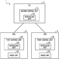
- FIG. 2 illustrates a first case where the centralized radio base station 1 composed of the CU 11 and the DU 12 performs scheduling of radio communication.
- FIG. 2 illustrates a case where the CU 11 intensively performs the scheduling of each radio communication performed by each DU 12 . This is conceivable to be the most general form of scheduling in the centralized radio base station 1 .
- the CU 11 includes a control unit, and the control unit includes a scheduling unit.
- each DU 12 includes a radio section.
- scheduling of radio communication may be paraphrased as a process of determining the mode of each radio communication.
- many parameters related to radio communication are determined, such as the timing of radio communication (corresponding to a subframe in LTE or the like), subcarriers used for radio communication (corresponding to a resource block in LTE or the like), modulation schemes and coding schemes applied to radio communication (Modulation and Coding Scheme (MCS)) in LTE or the like), and the like.
- scheduling of radio communication includes, for example, processing of determining whether coordinated multiple point transmission is applied, processing of controlling segmentation and reassembly (concatenation) for RLC PDUs, and the like.
- Scheduling of such radio communication is generally performed based on radio quality (quality of radio communication path).
- radio quality quality of radio communication path.
- SNR Signal-to-Noise Ratio
- SINR Signal-to-Interference plus Noise Ratio
- SNDR Signal-to-Noise plus Distortion Ratio
- the radio terminal 2 measures the radio quality based on a reference signal (standard signal, pilot signal) in downlink radio signals and transmits a feedback signal (feedback information) to the base station based on the measurement result.
- the base station may perform scheduling of downlink communication based on this feedback signal.
- This feedback signal is called Channel State Information (CSI) in LTE or the like.
- CSI for example, Channel Quality Information (CQI), Precoding Matrix Indicator (PMI), and Rank Indicator (RI) may be used.
- CSI is a type of uplink control information (UCI).
- the radio base station 1 itself may measure the radio quality based on the reference signal (standard signal) in the uplink radio signals.
- the base station may perform scheduling of the uplink communication based on the measurement result.
- scheduling of radio communication is generally performed based on radio quality. For example, for the timing of radio communication, radio communication is performed with the best possible radio quality. In addition, for subcarriers used for radio communication, radio communication is performed by using subcarriers with the best possible radio quality. Various other matters determined in the scheduling of radio communication are also based on radio quality.
- the CU 11 and each DU 12 are connected via a network called a front hole.
- a network having a relatively small delay that is, low delay or high speed
- a relatively large delay that is, high delay or low speed
- electric wire and radio a front hole with no delay or relatively small delay
- a front hole with a relatively large delay is called a non-ideal front hole.
- a non-ideal front hole may be assumed from the viewpoint of cost and the like.
- an ideal front hole and a non-ideal front hole may be mixed.
- the radio terminal 2 measures the radio quality based on a reference signal in downlink radio signals and transmits a feedback signal to the base station based on the measurement result.
- the base station performs scheduling based on the feedback signal, and a downlink radio signal (including data and the like) is transmitted based on the scheduling result.
- a feedback signal indicating the radio quality may be delivered from the radio terminal 2 (not illustrated) to the CU 11 via the DU 12 .
- the front hole is non-ideal, since the propagation delay between the DU 12 and the CU 11 is relatively large, it is difficult to reflect the latest radio quality in the scheduling.
- the problem in downlink communication is pointed out, but it is to be noted that the circumstances remain unchanged even in uplink communication.
- FIG. 3 illustrates a second case where the centralized radio base station 1 performs scheduling of radio communication.
- FIG. 3 illustrates a case where each DU 12 performs scheduling of each radio communication performed by each DU 12 in a distributed manner.
- each DU 12 includes a control unit, and the control unit includes a scheduling unit.
- each DU 12 also includes a radio unit.
- the problem described with reference to FIG. 2 does not occur.
- scheduling of radio communication is performed in each DU 12 so that information related to the radio quality for scheduling and information indicating the scheduling result is not transmitted and received via the front hole.
- Examples of such a control include inter-cell interference control (ICIC) in addition to CoMP transmission and reception as described above.
- ICIC inter-cell interference control
- These techniques in LTE have been introduced with the aim of improving the characteristics of radio communication by coordinating between the cells.
- the radio base station 1 illustrated in FIG. 3 since it is difficult to perform these various kinds of control, it may be assumed that the case where the characteristics of the radio communication may not be sufficiently established occurs.
- the centralized radio base station 1 may not perform scheduling of radio communication flexibly.
- viewpoints of this deficiency may be considered, but here, as an example, the description was made from one viewpoint. Again, this deficiency has been found by a fine examination by the inventor of the present application.
- scheduling of radio communication includes various functions, and in the above description, the case where all of these various functions are implemented in either CU 11 or DU 12 is described. However, it is to be noted that even in a case where some of these various functions are implemented in the CU 11 and others are implemented in the DU 12 , the above-described problem occurs at least in part.
- the first embodiment is based on the radio base station 1 includes a first device (for example, DU 12 ) that includes a radio unit 121 that performs radio communication with a radio terminal 2 and a first control unit 122 that controls the radio communication and a second device (for example, CU 11 ) that is connected to the first device via a network and includes a second control unit 111 that controls the radio communication, in which a first scheduling function that is at least a part of a scheduling function for the radio communication of the first control unit 122 and a second scheduling function that is at least a part of a scheduling function for the radio communication of the second control unit 111 are redundant.
- a first device for example, DU 12
- a radio unit 121 that performs radio communication with a radio terminal 2 and a first control unit 122 that controls the radio communication
- a second device for example, CU 11
- the centralized radio base station 1 as illustrated in FIGS. 2 and 3 may not perform scheduling of radio communication flexibly.
- viewpoints of this deficiency may be considered, but as an example, the description was made from two viewpoints.
- the cause of these deficiencies is that in the centralized radio base station 1 illustrated in FIG. 2 , only the CU 11 is provided with a scheduling unit (scheduling function) and in the centralized radio base station 1 illustrated in FIG. 3 , only the DU 12 is provided with a scheduling unit (scheduling function). That is, it is conceivable that the cause of these deficiencies is that, after all, in the centralized radio base station 1 illustrated in FIGS. 2 and 3 , one of the CU 11 and the DU 12 is mutually exclusively provided with a scheduling function.
- the CU 11 and the DU 12 are provided with a scheduling unit (scheduling function) redundantly. That is, the second control unit 111 in the CU 11 is provided with the scheduling unit 112 , and the first control unit 122 in each DU 12 is provided with a scheduling unit 123 .
- the radio base station 1 may appropriately select and use the scheduling function redundant in the CU 11 and the DU 12 according to the situation. As a result, it is conceivable that the above-described deficiency in the centralized radio base station 1 illustrated in FIGS. 2 and 3 is solved.
- the “scheduling function” may be replaced with the “scheduling unit” as appropriate.
- the difference between these terms is only emphasizing the function or emphasizing the structure, and there is not much significance in considering the substantial difference.
- the base station according to the first embodiment illustrated in FIG. 4 since the CU 11 and the DU 12 are provided with the scheduling function redundantly, it is possible to use the scheduling function of the DU 12 side in a case where the front hole is non-ideal, and use the scheduling function of the CU 11 side in a case where the front hole is ideal.
- the configuration illustrated in FIG. 4 may also be expected to be advantageous at least from the other three viewpoints. All of these viewpoints were obtained from a detailed analysis of the inventor. In the following, these three viewpoints will be referred to as the second to fourth viewpoints and will be described in order.
- the CU 11 is responsible for scheduling all the DUs 12 . Therefore, although the CU 11 generally has relatively large computer resources (CPU power, memory capacity, and the like), it may be assumed that the processing load of the CU 11 becomes excessively high, which may cause problems in scheduling and other processing in the CU 11 .
- each DU 12 itself is responsible for scheduling for each DU 12 .
- each DU 12 may only perform scheduling of radio communication by itself, but in general, the computer resources of DU 12 are relatively small. For this reason, for example, in a case where retransmission frequently occurs in the radio unit, it may be assumed that the processing load on the DU 12 increases, which may cause problems in scheduling and other processing in the DU 12 .
- the radio base station 1 according to the first embodiment illustrated in FIG. 4 since the CU 11 and the DU 12 are provided with the scheduling function redundantly, it is possible to use the scheduling function of the DU 12 side in a case where the load of the CU 11 is high and to use the scheduling function of the CU 11 side in a case where the load of the DU 12 is high.
- the third viewpoint on the advantages of the radio base station 1 in FIG. 4 will be described.
- baseband processing and the like are performed by the DU 12 , so that the signal of a lower layer never transmits through the front hole.
- the configuration illustrated in FIG. 2 it is also possible to perform, for example, the baseband processing with the CU 11 , in which case a signal of a lower layer is transmitted in the front hole.
- the signal of the lower layer is, for example, a Layer 1 (L1) signal.
- the radio communication uses a millimeter wave (30 GHz to 300 GHz).
- the millimeter wave is high in rectilinearity and is intended for so-called line-of-sight communication, but since there are many unused bands and large capacity communication is possible, the millimeter wave is a frequency band expected to be utilized in 5G systems.
- the determination as to whether to adopt either the configuration in FIG. 2 or the configuration in FIG. 3 differs depending on the frequency band used by the radio communication.
- the configurations in FIGS. 2 and 3 have a deficiency that the configurations may not sufficiently deal with only one of the millimeter wave band and the frequency band in the related art. Further, the configurations in FIGS. 2 and 3 may not dynamically cope with the change of the frequency band used by radio communication.
- the radio base station 1 according to the first embodiment illustrated in FIG. 4 since the CU 11 and the DU 12 are provided with the scheduling function redundantly, it is possible to use the scheduling function of the DU 12 side in a case where radio communication uses the millimeter wave and to use the scheduling function of the CU 11 side in a case where the radio communication uses the frequency band of the cellular communication in the related art.
- the radio base station 1 according to the first embodiment illustrated in FIG. 4 since the CU 11 and the DU 12 are provided with the scheduling function redundantly, it is possible to use the scheduling function of the DU 12 side in a case where radio communication uses the millimeter wave and to use the scheduling function of the CU 11 side in a case where the radio communication uses the frequency band of the cellular communication in the related art.
- the configuration in FIG. 3 is preferable in a case where the front hole is non-ideal.
- traffic for example, traffic by smart meters in IoT (Internet of Things)
- IoT Internet of Things
- actual damage is small. Therefore, even if the front hole is non-ideal, it is conceivable that there is no problem in adopting the configuration in FIG. 2 for traffic that may tolerate a delay.
- traffic that may not tolerate delay such as real-time data
- the configuration in FIG. 3 is preferable in principle.
- the radio base station 1 according to the first embodiment illustrated in FIG. 4 since the CU 11 and the DU 12 are provided with the scheduling function redundantly, it is possible to use the scheduling function of the CU 11 side in a case where the traffic may tolerate the delay and to use the scheduling function of the DU 12 side in a case where the traffic may not tolerate the delay.
- the radio base station 1 according to the first embodiment illustrated in FIG. 4 it is possible to raise the priority of using the scheduling function of the CU 11 side in a case where the traffic may tolerate the delay and to raise the priority of using the scheduling function of the DU 12 side in a case where the traffic may not tolerate the delay.
- the scheduling of radio communication includes various functions, and in the radio base station 1 according to the first embodiment, it goes without saying that all of these various functions may be provided redundantly in the CU 11 and the DU 12 . However, in the radio base station 1 according to the first embodiment, it is to be noted that at least some of these various functions may be provided redundantly in the CU 11 and the DU 12 .
- the scheduling function is generally configured hierarchically in general, but among the scheduling functions, functions of a relatively lower layer may be provided redundantly in the CU 11 and the DU 12 , and other relatively higher layer functions may be provided only in the CU 11 . As a result, it is possible to obtain the effect of the present invention with respect to the functions of the relatively lower layer which are provided redundantly by the CU 11 and the DU 12 .
- the first embodiment described above it is possible to solve the deficiencies in the centralized type radio base station 1 from the two viewpoints regarding the flexibility of the radio scheduling described above. Therefore, according to the first embodiment, a remarkable effect that it is possible to perform scheduling of radio communication flexibility is exerted, which is not obtained in the related art.
- the second embodiment is the radio base station 1 according to the first embodiment, and the second control unit 111 is based on the radio base station 1 that selects which one of the first scheduling function and the second scheduling function performs scheduling of the radio communication.
- the scheduling function of radio communication is provided redundantly in the CU 11 and the DU 12 .
- the radio base station 1 according to the second embodiment is an added configuration in which the CU 11 dynamically selects which one of the CU 11 side and the DU 12 side to use the scheduling function under the premise of the base station according to the first embodiment.
- FIG. 5 illustrates the radio base station 1 according to the second embodiment.
- the radio base station 1 illustrated in FIG. 5 is different from the radio base station 1 illustrated in FIG. 4 in that a selection unit 113 is added to the second control unit 111 on the CU 11 side.
- the selection unit 113 selects which one of the CU 11 side and the DU 12 side to use the scheduling function.
- the above selection made by the CU 11 may be made based on various criteria.
- selection criteria in accordance with the above-described first viewpoint, the CU 11 may select the DU 12 side in a case where the front hole is non-ideal and may select the CU 11 side in a case where the front hole is ideal.
- the front hole is non-ideal or ideal, but this may be determined based on the type of the communication interface of the front hole, or it may be determined based on the communication delay of the front hole or the measured value of the Round Trip Time (RTT).
- RTT Round Trip Time
- the CU 11 may select the DU 12 side in a case where the load of the CU 11 is high (for example, in the case of being equal to or greater than a first predetermined value) and may select the CU 11 side in a case where the load of the DU 12 is high (for example, generally, in the case of being equal to or greater than a second predetermined value smaller than the first predetermined value).
- index values may be used as the load of the CU 11 and the DU 12 , and for example, a CPU usage rate, a memory usage rate, or the like may be used. In addition, for example, it is possible to determine the load of the CU 11 or the DU 12 based on the number of the connected radio terminals 2 .
- either the scheduling function of CU 11 or DU 12 may be used, but in such a case, for example, the scheduling function of CU 11 may be fixedly used.
- the scheduling function of CU 11 may be fixedly used.
- the CU 11 may select the DU 12 side in a case where the radio communication uses the millimeter wave and may select the CU 11 side in a case where the radio communication uses the frequency band of the cellular communication in the related art.
- the radio communication uses the millimeter wave
- the CU 11 may select the CU 11 side in a case where the traffic may tolerate the delay and may select the DU 12 side in a case where the traffic may not tolerate the delay.
- the criteria of the above four selections may be used alone, or some of the criteria may be combined.
- the priority (standard weight) in the case of combining several criteria may be adjusted as appropriate.
- the scheduling function of the one selected from the CU 11 side and the DU 12 side is activated.
- the scheduling function of the one of the CU 11 side and the DU 12 side which has not been selected has already been activated
- the scheduling function is deactivated.
- the CU 11 may notify or transmit information or a signal instructing that the activating or stopping to the DU 12 via the front hole.
- the CU 11 may perform the scheduling of radio communication performed by the DU 12 in a fixed manner by the CU 11 .
- the above selection unit may be selected appropriately and may be, for example, a traffic flow unit or a bearer unit.
- the scheduling function in the base station includes, for example, the functions of selection (routing) of DU 12 , segmentation or concatenation of upper packets, adaptive modulation coding (AMC: Adaptive Modulation and Coding), and other functions (for example, radio resource selection, transmission data amount selection, selection of the radio terminal 2 for performing communication, and the like).
- AMC adaptive modulation coding
- other functions for example, radio resource selection, transmission data amount selection, selection of the radio terminal 2 for performing communication, and the like.
- the selection function (routing) of the DU 12 is naturally provided by the CU 11 .
- the CU 11 or the DU 12 is provided with segmentation or concatenation function and the functions such as AMC and the like.
- segmentation or concatenation function, and functions such as AMC and the like are provided redundantly in both the CU 11 and the DU 12 .
- an adaptation function has been added, but this is a function that is not provided in the radio base station 1 such as the LTE system in the related art.
- the adaptation function is a function of selecting one of the CU 11 and the DU 12 based on various criteria, and the adaptation function on the CU 11 side, in particular, corresponds to the selection unit 113 in the second embodiment.
- each scheduling function in the radio base station 1 according to the third embodiment operates in accordance with the selection criteria based on the above-described first viewpoint. It goes without saying that the other selection criteria described above may be considered similarly to the description below.
- FIG. 7 is a diagram illustrating an example of the state of the operation of the radio base station 1 according to the third embodiment in a case where both of the two front holes are ideal.
- the dot pattern portion indicates the activated scheduling function
- the shaded pattern portion indicates the deactivated scheduling function.
- all functions of routing, segmentation or concatenation functions, AMC, and the like in the CU 11 are activated, and all functions of segmentation or concatenation function, AMC, and the like in the DU 12 are all stopped. Activation and stop of each function are controlled by an adaptation function.
- FIG. 8 is a diagram illustrating another example of the state of the operation of the radio base station 1 according to the third embodiment in a case where both of the two front holes are ideal.
- functions of routing, segmentation or concatenation in the CU 11 are activated, and functions such as AMC and the like in the CU 11 are stopped.
- the segmentation or concatenation function in the DU 12 is stopped, and functions such as AMC and the like in the CU 11 are activated. Activation and stop of each function are controlled by an adaptation function.
- FIG. 9 is a diagram illustrating an example of the state of the operation of the radio base station 1 according to the third embodiment in a case where both of the two front holes are non-ideal.
- routing in the CU 11 is activated, and segmentation or concatenation function, and functions such as AMC and the like in the CU 11 are stopped.
- the segmentation or concatenation function in the DU 12 and the functions such as AMC and the like are activated. Activation and stop of each function are controlled by an adaptation function.
- FIG. 10 is a diagram illustrating an example of the state of the operation of the radio base station 1 according to the third embodiment in a case where one of the two front holes is ideal and the other is non-ideal.
- routing in the CU 11 is activated.
- the segmentation or concatenation function in the CU 11 and the functions such as AMC are also activated, and the segmentation or concatenation function in the DU 12 and the functions such as AMC are stopped.
- the segmentation or concatenation function in the CU 11 and the functions such as AMC are stopped, and the segmentation or concatenation function in the DU 12 and the functions such as AMC are activated.
- Activation and stop of each function are controlled by an adaptation function.
- FIG. 11 is a diagram illustrating an example of a hardware configuration of the radio base station 1 .
- the radio base station 1 is provided with a CU 11 and each DU 12 , and a network (front hole) is connected therebetween.
- the CU 11 is provided with, for example, a processor 1111 , a memory 1112 , and a communication IF (interface) 1113 .
- each DU 12 is provided with, for example, a processor 1121 , a memory 1122 , a communication IF 1123 , an RF circuit 1124 , and an antenna 1125 .
- the processor 1111 provided in the CU 11 and the processor 1121 provided in each DU 12 are, for example, a Central Processing Unit (CPU) or a Digital Signal Processor (DSP).
- the processor 1111 provided in the CU 11 and the processor 1121 provided in each DU 12 may be realized by a digital electronic circuit. Examples of the digital electronic circuit include Field-Programming Gate Array (FPGA), Application Specific Integrated Circuit (ASIC), Large Scale Integration (LSI), and the like.
- FPGA Field-Programming Gate Array
- ASIC Application Specific Integrated Circuit
- LSI Large Scale Integration
- the memory 1112 provided in the CU 11 and the memory 1121 provided in each DU 12 include at least one of Random Access Memory (RAM) such as Synchronous Dynamic Random Access Memory (SDRAM), a Read Only Memory (ROM), and a flash memory and store programs, control information, and data.
- RAM Random Access Memory
- SDRAM Synchronous Dynamic Random Access Memory
- ROM Read Only Memory
- flash memory stores programs, control information, and data.
- the radio base station 11 may be provided with an auxiliary storage device (hard disk or the like) not illustrated and the like.
- the communication IF 1113 provided in the CU 11 and the communication IF 1123 provided in each DU 12 are communication interfaces using, for example, an optical fiber, electric wire, radio, or the like.
- the second control unit 111 in the CU 11 is realized by, for example, a processor 1111 , a memory 1112 , a digital electronic circuit (not illustrated), and the like.
- the radio unit 121 in each DU 12 is realized by, for example, an RF circuit 1124 , an antenna 1125 , an analog electronic circuit (not illustrated), and the like.
- the first control unit 122 in the DU 12 is realized by, for example, a processor 1121 , a memory 1122 , a digital electronic circuit (not illustrated), and the like.
Abstract
Description
Claims (27)
Applications Claiming Priority (1)
| Application Number | Priority Date | Filing Date | Title |
|---|---|---|---|
| PCT/JP2016/002370 WO2017195238A1 (en) | 2016-05-13 | 2016-05-13 | Wireless base station and wireless communication method |
Related Parent Applications (1)
| Application Number | Title | Priority Date | Filing Date |
|---|---|---|---|
| PCT/JP2016/002370 Continuation WO2017195238A1 (en) | 2016-05-13 | 2016-05-13 | Wireless base station and wireless communication method |
Publications (2)
| Publication Number | Publication Date |
|---|---|
| US20190075577A1 US20190075577A1 (en) | 2019-03-07 |
| US11147082B2 true US11147082B2 (en) | 2021-10-12 |
Family
ID=60267687
Family Applications (1)
| Application Number | Title | Priority Date | Filing Date |
|---|---|---|---|
| US16/184,171 Active US11147082B2 (en) | 2016-05-13 | 2018-11-08 | Radio base station, central apparatus, and distributed apparatus |
Country Status (4)
| Country | Link |
|---|---|
| US (1) | US11147082B2 (en) |
| EP (1) | EP3457795B1 (en) |
| JP (1) | JP6798552B2 (en) |
| WO (1) | WO2017195238A1 (en) |
Families Citing this family (5)
| Publication number | Priority date | Publication date | Assignee | Title |
|---|---|---|---|---|
| US10992588B2 (en) * | 2016-10-26 | 2021-04-27 | Telefonaktiebolaget Lm Ericsson (Publ) | 5G congestion control |
| EP3618485A4 (en) * | 2017-04-27 | 2021-05-05 | Mitsubishi Electric Corporation | Communication system |
| MX2020005089A (en) * | 2017-11-17 | 2020-08-13 | Ntt Docomo Inc | Communication device and communication method. |
| WO2023002538A1 (en) * | 2021-07-19 | 2023-01-26 | 日本電信電話株式会社 | Signal transfer control device, signal transfer control method, signal transfer control program, and signal transfer system |
| JPWO2023002539A1 (en) * | 2021-07-19 | 2023-01-26 |
Citations (12)
| Publication number | Priority date | Publication date | Assignee | Title |
|---|---|---|---|---|
| WO2013076899A1 (en) | 2011-11-25 | 2013-05-30 | 日本電気株式会社 | Wireless station and method of processing user data with wireless station |
| WO2014112597A1 (en) | 2013-01-18 | 2014-07-24 | 京セラ株式会社 | Mobile communication system, user terminal, and base station |
| US20140226477A1 (en) * | 2011-10-19 | 2014-08-14 | Huawei Technologies Co., Ltd. | Method, Apparatus, and System for Improving user Experience of Small Flow User |
| US20150023282A1 (en) * | 2012-03-14 | 2015-01-22 | Sharp Kabushiki Kaisha | Terminal device, base station device, and integrated circuit |
| US20160073265A1 (en) * | 2014-09-08 | 2016-03-10 | Blackberry Limited | Method and Apparatus for Authenticating a Network Entity Using Unlicensed Wireless Spectrum |
| US20160119939A1 (en) * | 2014-10-23 | 2016-04-28 | Intel IP Corporation | Systems, methods, and appartatuses for bearer splitting in multi-radio hetnet |
| US20160198352A1 (en) * | 2015-01-05 | 2016-07-07 | Qualcomm Incorporated | System and Methods for Improving Data Performance Via Deliberate Hybrid Automatic Repeat Request (HARQ) Acknowledgment (ACK) and Fast Radio Link Control (RLC) Non-acknowledgment (NACK) in a Multi-Subscriber Identity Module (SIM) Wireless Communication Device |
| US20160285935A1 (en) * | 2015-03-27 | 2016-09-29 | Qualcomm Incorporated | Point-to-multipoint broadcast assisted vehicle-to-x broadcast |
| US20170134298A1 (en) * | 2015-11-05 | 2017-05-11 | Qualcomm Incorporated | System and Methods for Improving Support of a Virtual Subscriber Identity Module (SIM) in a Multi-SIM Wireless Communication Device |
| US20170257876A1 (en) * | 2015-01-30 | 2017-09-07 | Panasonic Intellectual Property Corporation Of America | Logical channel prioritization procedure for sidelink logical channels |
| US20180034669A1 (en) * | 2015-03-11 | 2018-02-01 | Phluido, Inc. | Distributed radio access network with adaptive fronthaul |
| US20180077608A1 (en) * | 2015-04-03 | 2018-03-15 | Lg Electronics Inc. | Source ID-Based Packet Filtering Method in Wireless Communication System and Terminal Using Method |
-
2016
- 2016-05-13 EP EP16901587.2A patent/EP3457795B1/en active Active
- 2016-05-13 WO PCT/JP2016/002370 patent/WO2017195238A1/en unknown
- 2016-05-13 JP JP2018516664A patent/JP6798552B2/en active Active
-
2018
- 2018-11-08 US US16/184,171 patent/US11147082B2/en active Active
Patent Citations (16)
| Publication number | Priority date | Publication date | Assignee | Title |
|---|---|---|---|---|
| US20140226477A1 (en) * | 2011-10-19 | 2014-08-14 | Huawei Technologies Co., Ltd. | Method, Apparatus, and System for Improving user Experience of Small Flow User |
| US20140269603A1 (en) | 2011-11-25 | 2014-09-18 | Nec Corporation | Radio Station and Method of Processing User Data With Radio Station |
| US20160044637A1 (en) * | 2011-11-25 | 2016-02-11 | Nec Corporation | Radio station and method of processing user data with radio station |
| WO2013076899A1 (en) | 2011-11-25 | 2013-05-30 | 日本電気株式会社 | Wireless station and method of processing user data with wireless station |
| US20150023282A1 (en) * | 2012-03-14 | 2015-01-22 | Sharp Kabushiki Kaisha | Terminal device, base station device, and integrated circuit |
| US9877351B2 (en) * | 2013-01-18 | 2018-01-23 | Kyocera Corporation | Mobile communication system, user terminal, and base station |
| WO2014112597A1 (en) | 2013-01-18 | 2014-07-24 | 京セラ株式会社 | Mobile communication system, user terminal, and base station |
| US20150341977A1 (en) | 2013-01-18 | 2015-11-26 | Kyocera Corporation | Mobile communication system, user terminal, and base station |
| US20160073265A1 (en) * | 2014-09-08 | 2016-03-10 | Blackberry Limited | Method and Apparatus for Authenticating a Network Entity Using Unlicensed Wireless Spectrum |
| US20160119939A1 (en) * | 2014-10-23 | 2016-04-28 | Intel IP Corporation | Systems, methods, and appartatuses for bearer splitting in multi-radio hetnet |
| US20160198352A1 (en) * | 2015-01-05 | 2016-07-07 | Qualcomm Incorporated | System and Methods for Improving Data Performance Via Deliberate Hybrid Automatic Repeat Request (HARQ) Acknowledgment (ACK) and Fast Radio Link Control (RLC) Non-acknowledgment (NACK) in a Multi-Subscriber Identity Module (SIM) Wireless Communication Device |
| US20170257876A1 (en) * | 2015-01-30 | 2017-09-07 | Panasonic Intellectual Property Corporation Of America | Logical channel prioritization procedure for sidelink logical channels |
| US20180034669A1 (en) * | 2015-03-11 | 2018-02-01 | Phluido, Inc. | Distributed radio access network with adaptive fronthaul |
| US20160285935A1 (en) * | 2015-03-27 | 2016-09-29 | Qualcomm Incorporated | Point-to-multipoint broadcast assisted vehicle-to-x broadcast |
| US20180077608A1 (en) * | 2015-04-03 | 2018-03-15 | Lg Electronics Inc. | Source ID-Based Packet Filtering Method in Wireless Communication System and Terminal Using Method |
| US20170134298A1 (en) * | 2015-11-05 | 2017-05-11 | Qualcomm Incorporated | System and Methods for Improving Support of a Virtual Subscriber Identity Module (SIM) in a Multi-SIM Wireless Communication Device |
Non-Patent Citations (16)
| Title |
|---|
| A replacement European Search Report issued for European Patent Application No. 16901587.2, with Supplementary European Search Report and written opinion, dated Sep. 17, 2019. |
| Communication pursuant to Article 94(3) EPC issued by the European Patent Office for corresponding European Patent Application No. 16 901 587.2-1215, dated Oct. 29, 2020. |
| Decision of Refusal issued by the Japan Patent Office for corresponding Japanese Patent Application No. 2018-516664, dated Jun. 2, 2020, with an English translation. |
| Extended European search report with supplementary European search report and the European search opinion issued by the European Patent Office for corresponding European Patent Application No. 16901587.2, dated Mar. 18, 2019. |
| Fujitsu, "Adaptation Function for Fronthauling", Agenda Item: 9.4.2 (User Plane), 3GPP TSG-RAN WG2 Meeting #94, R2-163774, Nanjing, China, May 23-27, 2016. |
| International Search Report issued by the Japan Patent Office for corresponding International Patent Application No. PCT/JP2016/002370, dated Nov. 1, 2016, with an English translation. |
| LG Electronics Inc., "5G user plane protocol design", Agenda Item: 9.2, 3GPP TSG-RAN WG2 Meeting #93bis, R2-162861, Dubrovnik, Croatia, Apr. 11-15, 2016. |
| LG Electronics, "Consideration on CoMPSimulation Assumption", Agenda Item: 6.3.1.1, 3GPP TSG-RAN WG1 meeting #63bis, R1-110383, Dublin, Ireland, Jan. 17-21, 2011. |
| NIT Docomo, Inc., "Overall radio protocol and NW architecture for NR", Agenda Item: 10.2, 3GPP TSG-RAN WG3 meeting #91 bis, R3-160829, Bangalore, India, Apr. 11-15, 2016. (Year: 2016). * |
| Nokia Siemens Networks et al., "Cell aggregation: A unified approach to CoMP and carrier aggregation", Agenda Item: 6.3.1.3, 3GPP TSG-RAN WG1 meeting #65, R1-111737, Barcelona, Spain, May 9-13, 2011. |
| Notice of Reasons for Refusal issued by the Japan Patent Office for corresponding Japanese Patent Application No. 2018-516664, dated Feb. 4, 2020, with an English translation. |
| NTT Docomo, Inc., "Overall radio protocol and NW architecture for NR", Agenda Item: 10.2, 3GPP TSG-RAN WG3 meeting #91bis, R3-160829, Bangalore, India, Apr. 11-15, 2016. |
| Samsung, "Function split between central and remote node", Agenda Item: 10.5, 3GPP TSG-RAN WG3 meeting #91bis, R3-161013, Bangalore, India, Apr. 11-15, 2016. |
| Written Opinion of the International Searching Authority issued by the Japan Patent Office for corresponding International Patent Application No. PCT/JP2016/002370, dated Nov. 1, 2016, with an English translation. |
| ZTE, "Signalling for inter-eNB CoMP with non-ideal backhaul", Agenda Item: 6.2.9.2, 3GPP TSG-RAN WG1 Meeting #75, R1-135377, San Francisco, USA, Nov. 11-15, 2013. |
| ZTE, "Signalling for inter-eNB CoMP with non-ideal backhaul", Agenda Item: 6.2.9.2, 3GPP TSG-RAN WG1 Meeting #75, R1-135377, San Francisco, USA, Nov. 11-15, 2013. (Year: 2013). * |
Also Published As
| Publication number | Publication date |
|---|---|
| US20190075577A1 (en) | 2019-03-07 |
| EP3457795A1 (en) | 2019-03-20 |
| WO2017195238A1 (en) | 2017-11-16 |
| EP3457795B1 (en) | 2022-03-23 |
| JP6798552B2 (en) | 2020-12-09 |
| EP3457795A4 (en) | 2019-04-17 |
| JPWO2017195238A1 (en) | 2019-03-14 |
Similar Documents
| Publication | Publication Date | Title |
|---|---|---|
| US11147082B2 (en) | Radio base station, central apparatus, and distributed apparatus | |
| US11134406B2 (en) | Measurement reporting method and apparatus | |
| CN108282321B (en) | Information indication method, network equipment and terminal equipment | |
| CN108400853B (en) | Reference signal configuration method and device and communication node | |
| EP2910060A1 (en) | Selection of access points for coordinated multipoint uplink reception | |
| US11088738B2 (en) | Communication method and network device | |
| US9450662B2 (en) | Evolved node-B, user equipment, and methods for channel quality indicator (CQI) feedback | |
| EP2944032A1 (en) | Adaptive use of receiver diversity | |
| US20210336712A1 (en) | Method for channel and interference measurement and device | |
| KR102358162B1 (en) | Method, apparatus and electronic device for determining beam reciprocity of a device | |
| JP6583409B2 (en) | Wireless communication control method, wireless communication system, receiving device, and transmitting device | |
| KR101585422B1 (en) | Methods and apparatus for precoding with limited coordination between cells in wireless communication system | |
| CN111435864B (en) | Method and device for transmitting channel state information | |
| CN112671442B (en) | Communication method and communication device | |
| US9929819B2 (en) | Opportunistic comp with low rate low latency feedback | |
| CN111970036A (en) | Communication method and communication device | |
| WO2019062491A1 (en) | Method for channel measurement | |
| CN108347274A (en) | A kind of method and device of the number of beams of indication feedback | |
| WO2021151855A1 (en) | Csi accuracy indicator reporting for mu-mimo broadcast channel | |
| WO2021077336A1 (en) | Method and apparatus for multi-user multi-antenna transmission | |
| CN113812093A (en) | Apparatus, method and computer program | |
| RU2779433C2 (en) | Communication method and communication device | |
| US20150215099A1 (en) | System and Method for Channel Quality Feedback |
Legal Events
| Date | Code | Title | Description |
|---|---|---|---|
| FEPP | Fee payment procedure |
Free format text: ENTITY STATUS SET TO UNDISCOUNTED (ORIGINAL EVENT CODE: BIG.); ENTITY STATUS OF PATENT OWNER: LARGE ENTITY |
|
| AS | Assignment |
Owner name: FUJITSU LIMITED, JAPAN Free format text: ASSIGNMENT OF ASSIGNORS INTEREST;ASSIGNORS:ODE, TAKAYOSHI;KAWASAKI, YOSHIHIRO;AIKAWA, SHINICHIRO;AND OTHERS;SIGNING DATES FROM 20181031 TO 20181105;REEL/FRAME:047496/0616 |
|
| STPP | Information on status: patent application and granting procedure in general |
Free format text: NON FINAL ACTION MAILED |
|
| STPP | Information on status: patent application and granting procedure in general |
Free format text: RESPONSE TO NON-FINAL OFFICE ACTION ENTERED AND FORWARDED TO EXAMINER |
|
| STPP | Information on status: patent application and granting procedure in general |
Free format text: FINAL REJECTION MAILED |
|
| STPP | Information on status: patent application and granting procedure in general |
Free format text: RESPONSE AFTER FINAL ACTION FORWARDED TO EXAMINER |
|
| STPP | Information on status: patent application and granting procedure in general |
Free format text: ADVISORY ACTION MAILED |
|
| STPP | Information on status: patent application and granting procedure in general |
Free format text: DOCKETED NEW CASE - READY FOR EXAMINATION |
|
| STPP | Information on status: patent application and granting procedure in general |
Free format text: RESPONSE TO NON-FINAL OFFICE ACTION ENTERED AND FORWARDED TO EXAMINER |
|
| STPP | Information on status: patent application and granting procedure in general |
Free format text: FINAL REJECTION MAILED |
|
| STPP | Information on status: patent application and granting procedure in general |
Free format text: DOCKETED NEW CASE - READY FOR EXAMINATION |
|
| STPP | Information on status: patent application and granting procedure in general |
Free format text: NON FINAL ACTION MAILED |
|
| STPP | Information on status: patent application and granting procedure in general |
Free format text: RESPONSE TO NON-FINAL OFFICE ACTION ENTERED AND FORWARDED TO EXAMINER |
|
| STPP | Information on status: patent application and granting procedure in general |
Free format text: NOTICE OF ALLOWANCE MAILED -- APPLICATION RECEIVED IN OFFICE OF PUBLICATIONS |
|
| STPP | Information on status: patent application and granting procedure in general |
Free format text: PUBLICATIONS -- ISSUE FEE PAYMENT VERIFIED |
|
| STCF | Information on status: patent grant |
Free format text: PATENTED CASE |