JP6798552B2 - Radio base stations, centralized equipment, and distributed equipment - Google Patents
Radio base stations, centralized equipment, and distributed equipment Download PDFInfo
- Publication number
- JP6798552B2 JP6798552B2 JP2018516664A JP2018516664A JP6798552B2 JP 6798552 B2 JP6798552 B2 JP 6798552B2 JP 2018516664 A JP2018516664 A JP 2018516664A JP 2018516664 A JP2018516664 A JP 2018516664A JP 6798552 B2 JP6798552 B2 JP 6798552B2
- Authority
- JP
- Japan
- Prior art keywords
- scheduling
- base station
- radio base
- wireless communication
- scheduling process
- Prior art date
- Legal status (The legal status is an assumption and is not a legal conclusion. Google has not performed a legal analysis and makes no representation as to the accuracy of the status listed.)
- Active
Links
Images


Classifications
-
- H—ELECTRICITY
- H04—ELECTRIC COMMUNICATION TECHNIQUE
- H04W—WIRELESS COMMUNICATION NETWORKS
- H04W72/00—Local resource management
- H04W72/12—Wireless traffic scheduling
-
- H—ELECTRICITY
- H04—ELECTRIC COMMUNICATION TECHNIQUE
- H04W—WIRELESS COMMUNICATION NETWORKS
- H04W88/00—Devices specially adapted for wireless communication networks, e.g. terminals, base stations or access point devices
- H04W88/08—Access point devices
- H04W88/085—Access point devices with remote components
-
- H—ELECTRICITY
- H04—ELECTRIC COMMUNICATION TECHNIQUE
- H04W—WIRELESS COMMUNICATION NETWORKS
- H04W16/00—Network planning, e.g. coverage or traffic planning tools; Network deployment, e.g. resource partitioning or cells structures
- H04W16/24—Cell structures
- H04W16/26—Cell enhancers or enhancement, e.g. for tunnels, building shadow
-
- H—ELECTRICITY
- H04—ELECTRIC COMMUNICATION TECHNIQUE
- H04W—WIRELESS COMMUNICATION NETWORKS
- H04W16/00—Network planning, e.g. coverage or traffic planning tools; Network deployment, e.g. resource partitioning or cells structures
- H04W16/24—Cell structures
- H04W16/32—Hierarchical cell structures
-
- H—ELECTRICITY
- H04—ELECTRIC COMMUNICATION TECHNIQUE
- H04W—WIRELESS COMMUNICATION NETWORKS
- H04W88/00—Devices specially adapted for wireless communication networks, e.g. terminals, base stations or access point devices
- H04W88/08—Access point devices
Landscapes
- Engineering & Computer Science (AREA)
- Computer Networks & Wireless Communication (AREA)
- Signal Processing (AREA)
- Mobile Radio Communication Systems (AREA)
Description
本発明は、無線基地局および無線通信方法に関する。 The present invention relates to wireless base stations and wireless communication methods.
近年、携帯電話システム(セルラーシステム)等の無線通信システムにおいて、無線通信の更なる高速化・大容量化等を図るため、次世代の無線通信技術について議論が行われている。例えば、標準化団体である3GPP(3rd Generation Partnership Project)では、LTE(Long Term Evolution)と呼ばれる通信規格や、LTEの無線通信技術をベースとしたLTE-A(LTE-Advanced)と呼ばれる通信規格が提案されており、これらは第4世代移動通信システム(いわゆる4Gシステム)として知られている。また、2015年9月に、これらに引き続く第5世代移動通信システム(いわゆる5Gシステム)の標準化に関する議論が3GPPにおいて本格的に開始されている。 In recent years, in wireless communication systems such as mobile phone systems (cellular systems), discussions have been held on next-generation wireless communication technologies in order to further increase the speed and capacity of wireless communication. For example, 3GPP (3rd Generation Partnership Project), a standardization organization, proposes a communication standard called LTE (Long Term Evolution) and a communication standard called LTE-A (LTE-Advanced) based on LTE wireless communication technology. These are known as 4th generation mobile communication systems (so-called 4G systems). In September 2015, discussions on the subsequent standardization of 5th generation mobile communication systems (so-called 5G systems) began in earnest at 3GPP.
一方、LTE等のセルラーシステムは既に広く普及しているが、これらは、多くの無線基地局が多くのセルを形成することにより成り立っている。そのため、近年は数多くの無線基地局が至る所に配置されるようになっている。 On the other hand, cellular systems such as LTE are already widespread, but these are made up of many radio base stations forming many cells. Therefore, in recent years, many radio base stations have been placed everywhere.
多くのセルを効率的に形成するための従来技術として、1台の無線基地局が複数のセルを形成する技術が知られている。このような無線基地局としては、例えば、1つの中央装置(CU: Central Unit)と1つ以上の分散装置(DU: Distributed Unit)とから構成される無線基地局が挙げられる。なお、DUは、遠隔装置(RU: Remote Unit)と呼ばれることもある。 As a conventional technique for efficiently forming many cells, a technique in which one radio base station forms a plurality of cells is known. Examples of such a radio base station include a radio base station composed of one central unit (CU) and one or more distributed units (DU). The DU is sometimes called a remote unit (RU: Remote Unit).
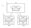
図1に、このような無線基地局1の一例を示す。図1においては、CU11と各DU12とは光ファイバ等のネットワーク(フロントホールと呼ばれる)により接続されている。そして、各DU12は、少なくとも無線部を含んでおり、各無線部は、それぞれがセルを形成するとともに、無線端末(UE: User Equipment)2と無線通信を行う。一方、CU11は、各無線端末2と各DU12との間の無線通信のスケジューリングの少なくとも一部を司る機能を有する。
FIG. 1 shows an example of such a
ここで、無線通信のスケジューリングとは、各無線通信の方式を決定する処理と言い換えることができる。無線通信のスケジューリングにおいては、例えば、無線通信のタイミング、無線通信に使用するサブキャリア、無線通信に適用される変調方式や符号化方式(符号化レート)等のように、無線通信に関する多くのパラメータが決定される。また、無線通信のスケジューリングは、広い意味では、例えば、多地点協調(CoMP: Coordinated Multiple Point)送受信の適用の有無や、あるいは、RLC(Radio Link Control) PDU(Protocol Data Unit)の分割や連結の決定等も含む。 Here, the scheduling of wireless communication can be rephrased as a process of determining the method of each wireless communication. In wireless communication scheduling, many parameters related to wireless communication such as timing of wireless communication, subcarriers used for wireless communication, modulation method and coding method (coding rate) applied to wireless communication, etc. Is determined. In a broad sense, wireless communication scheduling is, for example, whether or not Coordinated Multiple Point (CoMP) transmission / reception is applied, or division or connection of RLC (Radio Link Control) PDU (Protocol Data Unit). Including decisions, etc.
図1のような無線基地局1によれば、一つの無線基地局1が複数のセル(DU12の数に対応する数のセル)を形成できるようになる。これにより、多くのセルを効率的に形成することが可能となる。本願では、便宜上、このようにCU11とDU12とから構成される無線基地局1のアーキテクチャを「集中型」と称することとする。
According to the
上述したように、CU11とDU12とから構成される集中型の無線基地局1によれば、多くのセルを効率的に形成することが可能となる。しかしながら、本願発明者は、集中型の無線基地局1におけるスケジューリングについて、議論の余地があるものと考えている。
As described above, according to the centralized
特に、本願発明者による検討の結果、後述するように、所定の条件下で、集中型の無線基地局1において柔軟なスケジューリングを行うことができない場合があるという不備が見いだされた。
In particular, as a result of the study by the inventor of the present application, as will be described later, it has been found that the centralized
なお、上記の課題に至る説明はLTEに基づいて行ってきたが、所定の条件が揃えば、この課題は他の無線通信システムにも当てはまるものである。 Although the explanation leading to the above problem has been given based on LTE, this problem also applies to other wireless communication systems if predetermined conditions are met.
開示の技術は、上記に鑑みてなされたものであって、柔軟なスケジューリングを行うことができる集中型の無線基地局、無線通信システム、無線通信方法を提供することを目的とする。 The disclosed technology has been made in view of the above, and an object of the present invention is to provide a centralized radio base station, a radio communication system, and a radio communication method capable of performing flexible scheduling.
上述した課題を解決し、目的を達成するために、開示の無線基地局は、無線端末と無線通信を行う一以上の第1装置と、前記一以上の第1装置の各々とネットワークを介して接続された第2装置と、を備え、前記一以上の第1装置の各々は、前記無線通信に対するスケジューリング処理の少なくとも一部である第1スケジューリング処理を実行する第1スケジューリング部を有し、前記第2装置は、前記無線通信に対する前記スケジューリング処理の少なくとも一部である第2スケジューリング処理を実行する第2スケジューリング部を有し、前記第2スケジューリング処理は、前記第1スケジューリング処理よりも上位レイヤに関するスケジューリングを含む。 In order to solve the above-mentioned problems and achieve the object, the disclosed radio base station is used with one or more first devices for wireless communication with the wireless terminal and each of the one or more first devices via a network. Each of the one or more first devices including a connected second device has a first scheduling unit that executes a first scheduling process that is at least a part of the scheduling process for the wireless communication. The second apparatus has a second scheduling unit that executes a second scheduling process that is at least a part of the scheduling process for the wireless communication, and the second scheduling process relates to a layer higher than the first scheduling process. Includes scheduling.
本件の開示する無線基地局および無線通信方法の一つの態様によれば、集中型の無線基地局において柔軟なスケジューリングを行うことができるという効果を奏する。 According to one aspect of the wireless base station and the wireless communication method disclosed in the present case, there is an effect that flexible scheduling can be performed in the centralized wireless base station.
以下に、本件の開示する無線基地局および無線通信方法の実施形態を、図面を参照しながら説明する。なお、以下の実施形態により本件の開示する無線基地局および無線通信方法が限定されるものではない。 Hereinafter, embodiments of the wireless base station and the wireless communication method disclosed in this case will be described with reference to the drawings. The wireless base station and wireless communication method disclosed in this case are not limited by the following embodiments.
[問題の所在]
まず、各実施形態を説明する前に、従来技術における問題の所在を説明する。この問題は、本願発明者が従来技術を仔細に検討した結果として新たに見出したものであり、従来は知られていなかったものであることに注意されたい。[Location of the problem]
First, before explaining each embodiment, the location of a problem in the prior art will be described. It should be noted that this problem was newly discovered as a result of a detailed examination of the prior art by the inventor of the present application, and was not known in the past.
上述したように、CU11とDU12とから構成されるような集中型の無線基地局1によれば、多くのセルを効率的に形成することが可能となる。しかしながら、本願発明者による検討の結果、後述するように、所定の条件下で、集中型の無線基地局1において、無線通信のスケジューリングを柔軟に行うことができない場合があるという不備が見いだされた。
As described above, according to the centralized
この不備については、いくつかの観点が考えられるが、ここでは例として、1つの観点を説明する。 There are several possible viewpoints regarding this deficiency, but here, one viewpoint will be described as an example.
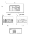
図2に、CU11とDU12とから構成されるような集中型の無線基地局1が無線通信のスケジューリングを行う第1の場合を示す。図2は、各DU12が行う各無線通信のスケジューリングを、CU11が集中的に行う場合を示している。これは、集中型の無線基地局1におけるもっとも一般的なスケジューリングの態様であるものと考えられる。
FIG. 2 shows a first case in which a centralized
図2において、CU11が制御部を備え、当該制御部がスケジューリング部を備えている。また、各DU12が無線部を備えている。
In FIG. 2, the
なお、本願の各図においては1つのCU11に2つのDU12(DU121およびDU122)が接続されている場合を例示しているが、1つのCU11に接続されるDU12の個数は任意で良いことは当然である。また、本願の各図においては、本件発明の説明に必要な機能以外の機能(例えばBB(base Band)処理機能等)は省略されているが、この点は、各図に示される無線基地局1等がそのような省略された機能を有していないことを意味しているわけではないことは言うまでもない。
In each drawing of the present application, the case where two DU 12s (DU 121 and DU 122) are connected to one
ここで、無線通信のスケジューリングについて再考する。無線通信のスケジューリングは、前述したように、各無線通信の方式を決定する処理と言い換えることができる。無線通信のスケジューリングにおいては、例えば、無線通信のタイミング(LTE等においてはサブフレームに相当)、無線通信に使用するサブキャリア(LTE等においてはリソースブロックに相当)、無線通信に適用される変調方式や符号化方式(LTE等においてはMCS(Modulation and Coding Scheme))等のように、無線通信に関する多くのパラメータが決定される。また、無線通信のスケジューリングは、広い意味では、例えば、多地点協調送受信の適用の有無や、あるいは、RLC PDUの分割(segmentation)や連結(concatenation)の決定等も含む。 Here, we reconsider the scheduling of wireless communication. As described above, the scheduling of wireless communication can be rephrased as the process of determining the method of each wireless communication. In wireless communication scheduling, for example, the timing of wireless communication (corresponding to a subframe in LTE etc.), the subcarrier used for wireless communication (corresponding to a resource block in LTE etc.), and the modulation method applied to wireless communication. Many parameters related to wireless communication are determined, such as MCS (Modulation and Coding Scheme) in LTE and the like. In a broad sense, wireless communication scheduling also includes, for example, whether or not multipoint coordinated transmission / reception is applied, and determination of segmentation and concatenation of RLC PDUs.
このような無線通信のスケジューリングは、一般に、無線品質(無線通信路の品質)に基づいて行われる。無線品質は、例えば、SNR(Signal-to-Noise Ratio)、SINR(Signal-to-Interference plus Noise Ratio)、SNDR(Signal-to-Noise plus Distortion Ratio)等を用いることができる。 Scheduling of such wireless communication is generally performed based on wireless quality (quality of wireless communication path). For the radio quality, for example, SNR (Signal-to-Noise Ratio), SINR (Signal-to-Interference plus Noise Ratio), SNDR (Signal-to-Noise plus Distortion Ratio) and the like can be used.
下り通信の場合、無線端末2が下りの無線信号中の参照信号(基準信号、パイロット信号)に基づいて無線品質を測定し、測定結果に基づいてフィードバック信号(フィードバック情報)を基地局に送信する。基地局は、このフィードバック信号に基づいて下り通信のスケジューリングを行うことができる。このフィードバック信号は、LTE等においてはCSI(Channel State Information)と呼ばれる。CSIとしては、例えばCQI(Channel Quality Information)、PMI(Precoding Matrix Indicator)、RI(Rank Indicator)を用いることができる。なお、CSIは、上り制御情報(UCI: Uplink Control Information)の一種である。
In the case of downlink communication, the
一方、上り通信の場合、無線基地局1が自分自身で上りの無線信号中の参照信号(基準信号)に基づいて無線品質を測定できる。基地局は、この測定結果に基づいて上り通信のスケジューリングを行うことができる。
On the other hand, in the case of uplink communication, the
いずれにしても、無線通信のスケジューリングは、一般に、無線品質に基づいて行われる。例えば、無線通信のタイミングに関しては、無線品質ができるだけ良いタイミングで無線通信が行われる。また、無線通信に用いられるサブキャリアに関しては、無線品質ができるだけ良いサブキャリアを用いて無線通信が行われる。無線通信のスケジューリングにおいて決定されるその他の種々の事項も、無線品質に基づいている。 In any case, scheduling of wireless communication is generally based on wireless quality. For example, regarding the timing of wireless communication, wireless communication is performed at the timing when the wireless quality is as good as possible. As for the subcarriers used for wireless communication, wireless communication is performed using the subcarriers having the best wireless quality. Various other matters determined in the scheduling of radio communications are also based on radio quality.
さて、上述したように、集中型の無線基地局1においては、CU11と各DU12の間がフロントホールと呼ばれるネットワークで接続されている。ここで、フロントホールとしては、光ファイバ等のような、遅延が比較的小さい(すなわち低遅延または高速な)ネットワークを使用するのが望ましい。しかしながら、場合によっては、フロントホールとして、電線や無線のような、遅延が比較的大きい(すなわち高遅延または低速な)ネットワークを用いざるを得ない場合もある。一般に、遅延がない、又は比較的小さいフロントホールは理想的(ideal)なフロントホールと呼ばれ、遅延が比較的大きいフロントホールは非理想的(non-ideal)なフロントホールと呼ばれる。
By the way, as described above, in the centralized
例えば、発展途上国等においては、コスト等の問題から、non-idealなフロントホールが想定されうる。もちろん、ある1つの無線基地局1において、idealなフロントホールとnon-idealなフロントホールが混在していても構わない。
For example, in developing countries, non-ideal front halls can be assumed due to problems such as cost. Of course, in one
ここで、集中型の無線基地局1において、フロントホールがnon-idealな場合について検討する。
Here, a case where the front hall is non-ideal in the centralized
前述したように、例えば下り通信の場合、無線端末2が下りの無線信号中の参照信号に基づいて無線品質を測定し、測定結果に基づいてフィードバック信号を基地局に送信する。基地局は、このフィードバック信号に基づいてスケジューリングを行い、スケジューリング結果に基づいて下りの無線信号(データ等を含む)が送信される。ここで、図2においては、スケジューリングを行うのはCU11であるため、無線品質を示すフィードバック信号が無線端末2(不図示)からDU12を経由してCU11に送り届けられる必要がある。ところが、フロントホールがnon-idealである場合、DU12とCU11との間の伝搬遅延が比較的大きいことにより、最新の無線品質をスケジューリングに反映させることが困難となる。なお、ここでは下り通信における問題を指摘したが、上り通信においても事情は変わらないことに留意されたい。
As described above, for example, in the case of downlink communication, the
したがって、図2に示されるような集中型の無線基地局1において、フロントホールがnon-idealな場合には、最新の無線品質を反映させたスケジューリングを行うことが困難という問題がある。
Therefore, in the centralized
次に、図3に、集中型の無線基地局1が無線通信のスケジューリングを行う第2の場合を示す。図3は、各DU12が行う各無線通信のスケジューリングを、各DU12が分散的に行う場合を示している。
Next, FIG. 3 shows a second case in which the centralized
図3においては、各DU12が制御部を備え、当該制御部がスケジューリング部を備えている。また、各DU12は無線部も備えている。
In FIG. 3, each
図3に示される無線基地局1においては、仮にフロントホールがnon-idealであっても、図2に基づいて説明したような問題は発生しないものと考えられる。図3に示される無線基地局1においては、無線通信のスケジューリングが各DU12内に閉じて行われることにより、スケジューリングに必要な無線品質の関する情報やスケジューリング結果を示す情報がフロントホールを介して送受信されない為である。
In the
しかしながら、図3に示される無線基地局1には、他の問題が発生しうると考えられる。具体的には、図3に示される無線基地局1では、無線通信のスケジューリングが各DU12内に閉じて行われるため、スケジューリングがセル毎に独立に行われることになる。そのため、図3に示される無線基地局1では、セル間で協調を行う各種制御を行うことが困難となる。
However, it is considered that other problems may occur in the
このような制御としては、例えば、前述したCoMP送受信に加え、セル間干渉制御(ICIC: Inter-Cell Interference Coordination)等を挙げることができる。LTEにおけるこれらの技術は、セル間で協調することによって無線通信の特性を改善することを目指して導入されたものである。図3に示される無線基地局1においては、これらの各種制御を行うことが困難となるため、無線通信の特性が十分に確保できない場合が発生することが想定されうる。
Examples of such control include cell-cell interference control (ICIC: Inter-Cell Interference Coordination) in addition to the above-mentioned CoMP transmission / reception. These technologies in LTE were introduced with the aim of improving the characteristics of wireless communication by coordinating between cells. In the
したがって、図2に示される集中型においては、フロントホールがnon-idealの場合に、最新の無線品質を反映させたスケジューリングを行うことが困難となる。一方、図3に示される集中型においては、セル間で協調を行う各種制御を行うことが困難となる。そのため、集中型の無線基地局1に対し、図2と図3のいずれの構成を採用しても、これらのいずれかの問題が生じることになると考えられる。この点が、前述した、集中型の無線基地局1におけるスケジューリングの柔軟性に関する1つの観点である。
Therefore, in the centralized type shown in FIG. 2, when the front hall is non-ideal, it is difficult to perform scheduling that reflects the latest radio quality. On the other hand, in the centralized type shown in FIG. 3, it is difficult to perform various controls for coordinating between cells. Therefore, it is considered that any of these problems will occur regardless of which of the configurations shown in FIGS. 2 and 3 is adopted for the centralized
以上をまとめると、集中型の無線基地局1において、無線通信のスケジューリングを柔軟に行うことができない場合があるという不備が存在する。この不備については、いくつかの観点が考えられるが、ここでは例として、1つの観点から説明を行った。繰り返しになるが、これらは、本願発明者により子細な検討から見いだされたものである。
Summarizing the above, there is a defect that the centralized
なお、上述したように無線通信のスケジューリングは種々の機能を含んでいるところ、上記の説明では、これら種々の機能の全てがCU11とDU12のいずれか一方に実装される場合を説明している。しかしながら、これら種々の機能の一部がCU11において実装され、他の一部がDU12において実装される場合においても、上記の問題が少なくとも部分的に発生することに留意されたい。
As described above, the scheduling of wireless communication includes various functions, and the above description describes the case where all of these various functions are implemented in either CU11 or DU12. However, it should be noted that even when some of these various functions are implemented in
また、上記の説明はLTE等に基づいて行ってきたが、所定の条件が揃えば、この説明は他の無線通信システムにも当てはまるものであることを付け加えておく。 In addition, although the above explanation has been given based on LTE and the like, it should be added that this explanation also applies to other wireless communication systems if certain conditions are met.
以下では、上記の問題を解決する各種実施形態を順に説明する。 Hereinafter, various embodiments for solving the above problems will be described in order.
[第1実施形態]
第1実施形態は、無線端末2と無線通信を行う無線部121と、前記無線通信を制御する第1制御部122とを備える第1装置(例えばDU12)と、前記第1装置とネットワークで接続され、前記無線通信を制御する第2制御部111を備える第2装置(例えばCU11)とを備え、前記第1制御部122が有する前記無線通信に対するスケジューリング機能の少なくとも一部である第1スケジューリング機能と、前記第2制御部111が有する前記無線通信に対するスケジューリング機能の少なくとも一部である第2スケジューリング機能とが重複する無線基地局1に基づく。[First Embodiment]
In the first embodiment, a first device (for example, DU 12) including a
第1実施形態の技術的意義を説明する。前述したように、図2や図3に示されるような集中型の無線基地局1において、無線通信のスケジューリングを柔軟に行うことができない場合があるという不備が存在する。この不備については、いくつかの観点が考えられるが、例として、2つの観点から説明を行った。
The technical significance of the first embodiment will be described. As described above, in the centralized
これらの不備の原因は、図2に示される集中型の無線基地局1においては、CU11のみがスケジューリング部(スケジューリング機能)を備えており、図3に示される集中型の無線基地局1においては、DU12のみがスケジューリング部(スケジューリング機能)を備えていることにあるものと考えられる。すなわち、これらの不備の原因は、結局のところ、図2や図3に示される集中型の無線基地局1において、CU11とDU12のいずれか一方が相互排他的にスケジューリング機能を備えていることに起因するものと考えられる。
The cause of these deficiencies is that in the centralized
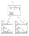
そこで、第1実施形態に係る集中型の無線基地局1においては、図4に示されるように、CU11とDU12とがスケジューリング部(スケジューリング機能)を重複して備えるものとしている。すなわち、CU11における第2制御部111がスケジューリング部112を備えるとともに、各DU12における第1制御部122がスケジューリング部123を備えている。こうすることで、無線基地局1は、CU11とDU12とに重複するスケジューリング機能を、状況に応じて適宜選択して使用することが可能となる。これにより、図2や図3に示される集中型の無線基地局1における前述の不備が解消されるものと考えられる。
Therefore, in the centralized
なお、以下の説明において、「スケジューリング機能」を「スケジューリング部」と適宜読み替えて構わない。これらの用語の違いは、機能を強調しているかあるいは構成を強調しているかに過ぎず、実質的な差を考慮する意義はあまりない為である。 In the following description, the "scheduling function" may be appropriately read as the "scheduling unit". This is because the difference between these terms is merely to emphasize the function or the structure, and it is not very meaningful to consider the substantial difference.
図4に示される第1実施形態に係る無線基地局の技術的意義を、より具体的に説明する。図2や図3に示される基地局においては、上述したように、例えば1つの観点からの不備が存在する。 The technical significance of the radio base station according to the first embodiment shown in FIG. 4 will be described more specifically. In the base stations shown in FIGS. 2 and 3, as described above, there are deficiencies from, for example, one viewpoint.
これに対し、図4に示される第1実施形態に係る基地局によれば、CU11とDU12とがスケジューリング機能を重複して備えているため、フロントホールがnon-idealである場合にDU12側のスケジューリング機能を使用するとともに、フロントホールがidealである場合にCU11側のスケジューリング機能を使用することができる。あるいは、図4に示される第1実施形態に係る基地局によれば、フロントホールがnon-idealである場合にDU12側のスケジューリング機能を使用する優先度を上げるとともに、フロントホールがidealである場合にCU11側のスケジューリング機能を使用する優先度を上げることができる。これにより、フロントホールがnon-idealである場合には、DU12側のスケジューリング機能により、最新の無線品質を反映させたスケジューリングを行うことが可能となる。また、フロントホールがidealである場合には、CU11側のスケジューリング機能により、セル間で協調を行う各種制御を行うことが可能となる。したがって、図4に示される第1実施形態に係る基地局によれば、図2や図3に基づいて説明した1つの観点からの不備を解消することができると考えられる。
On the other hand, according to the base station according to the first embodiment shown in FIG. 4, since the
上記の第1の観点に加えて、図4に示される構成は、少なくともその他の3つの観点からも利点が見込めるものと考えている。これらはいずれも発明者の子細な分析から得られたものである。以下ではこれら3つの観点を第2〜4の観点と称し、順に説明する。 In addition to the above first aspect, the configuration shown in FIG. 4 is considered to be advantageous from at least the other three viewpoints. All of these were obtained from a detailed analysis of the inventor. Hereinafter, these three viewpoints will be referred to as the second to fourth viewpoints and will be described in order.
まず、図4の無線基地局1の利点に関する第2の観点を説明する。上述した図2に示される無線基地局1においては、全てのDU12に対するスケジューリングをCU11が一手に担っている。そのため、一般にCU11は比較的大きな計算機資源(CPUパワーやメモリ量等)を有するものの、CU11の処理負荷が過度に高まり、CU11におけるスケジューリングやその他の処理に支障をきたすことが想定されうる。
First, a second viewpoint regarding the advantages of the
これに対し、上述した図3に示される集中型においては、各DU12に対するスケジューリングを各DU12自身が担っている。この場合、各DU12は自分が行う無線通信のスケジューリングのみを行えばよいが、一般にDU12の計算機資源は比較的小さい。そのため、例えば無線区間で再送が頻発している場合等において、DU12の処理負荷が高まり、DU12におけるスケジューリングやその他の処理に支障をきたすことが想定されうる。
On the other hand, in the centralized type shown in FIG. 3 described above, each
したがって、集中型の無線基地局1に対し、図2と図3のいずれの構成を採用しても、CU11の処理負荷の問題あるいはDU12の処理負荷の問題が生じることになると考えられる。さらに、図2や図3の構成は、CU11またはDU12における処理負荷の変化に動的に対応することもできない。これは、図2や図3の構成が、集中型の無線基地局1におけるスケジューリングの柔軟性に欠けるという不備があることを意味している。
Therefore, it is considered that the problem of the processing load of the
これに対し、図4に示される第1実施形態に係る無線基地局1によれば、CU11とDU12とがスケジューリング機能を重複して備えているため、CU11の負荷が高い場合にDU12側のスケジューリング機能を使用するとともに、DU12の負荷が高い場合にCU11側のスケジューリング機能を使用することができる。あるいは、図4に示される第1実施形態に係る無線基地局1によれば、CU11の負荷が高い場合にDU12側のスケジューリング機能を使用する優先度を上げるとともに、DU12の負荷が高い場合にCU11側のスケジューリング機能を使用する優先度を上げることができる。これにより、CU11の負荷が高い場合には、負荷分散により、CU11のそれ以上の過負荷を回避することが可能となる。また、DU12の負荷が高い場合にも、負荷分散により、DU12のそれ以上の過負荷を回避することが可能となる。また、図4の構成によれば、CU11またはDU12における処理負荷の変化に動的に対応することができる。したがって、図4に示される第1実施形態に係る基地局によれば、上述した不備を解消することができると考えられる。
On the other hand, according to the
次に、図4の無線基地局1の利点に関する第3の観点を説明する。図3に示される構成においては、ベースバンド処理等はDU12で行うことになるため、低レイヤの信号がフロントホールを伝送されることは無い。これに対し、図2に示される構成においては、例えばベースバンド処理までをCU11で行うことも可能であり、その場合には低レイヤの信号がフロントホールにおいて伝送されることになる。なお、低レイヤの信号とは、例えばL1(Layer 1)信号である。
Next, a third viewpoint regarding the advantages of the
したがって、低レイヤの信号の量が膨大となるような場合には、図2の構成が有する利点(セル間協調制御等)を失ったとしても、図2の構成よりも図3の構成の方が望ましい場合もあり得ると考えられる。このような場合の一例としては、無線通信がミリ波(30〜300GHz)を使用する場合が考えられる。ミリ波は直進性が高く、いわゆる見通し通信向けではあるが、未使用の帯域も多く、大容量通信が可能なため、5Gシステムにおいて活用が期待されている周波数帯となっている。 Therefore, in the case where the amount of signals in the low layer becomes enormous, the configuration of FIG. 3 is better than the configuration of FIG. 2 even if the advantages of the configuration of FIG. May be desirable in some cases. As an example of such a case, a case where wireless communication uses millimeter waves (30 to 300 GHz) can be considered. Millimeter waves have high straightness and are for so-called line-of-sight communication, but there are many unused bands and large-capacity communication is possible, so it is a frequency band that is expected to be used in 5G systems.
一方、従来のセルラー通信の周波数帯(4Gシステムで使用されている700Mhz帯〜3.5GHz帯等)においては、ミリ波のような特殊な事情は無いことから、原則的には図2の構成が有する利点を享受するのが望ましいものと考えられる。 On the other hand, in the conventional cellular communication frequency band (700Mhz band to 3.5GHz band used in 4G systems, etc.), there are no special circumstances such as millimeter waves, so in principle, the configuration shown in Fig. 2 is used. It is considered desirable to enjoy the benefits it has.
このように、無線通信が用いる周波数帯に応じて、図2の構成と図3の構成とのいずれを採用するかの判断が異なってくることが考えられる。しかしながら、図2や図3の構成は、ミリ波帯と従来の周波数帯との一方にしか十分に対応することができないという不備がある。さらに、図2や図3の構成は、無線通信が用いる周波数帯の変化に動的に対応することもできない。 As described above, it is conceivable that the determination of which of the configuration of FIG. 2 and the configuration of FIG. 3 is adopted differs depending on the frequency band used for wireless communication. However, the configurations of FIGS. 2 and 3 have a drawback that they can sufficiently correspond to only one of the millimeter wave band and the conventional frequency band. Further, the configurations of FIGS. 2 and 3 cannot dynamically respond to changes in the frequency band used in wireless communication.
これに対し、図4に示される第1実施形態に係る無線基地局1によれば、CU11とDU12とがスケジューリング機能を重複して備えているため、無線通信がミリ波を使用する場合にはDU12側のスケジューリング機能を使用するとともに、無線通信が従来のセルラー通信の周波数帯を使用する場合にCU11側のスケジューリング機能を使用することができる。あるいは、図4に示される第1実施形態に係る無線基地局1によれば、無線通信がミリ波を使用する場合にはDU12側のスケジューリング機能を使用する優先度を上げるとともに、無線通信が従来のセルラー通信の周波数帯を使用する場合にCU11側のスケジューリング機能を使用する優先度を上げることができる。また、図4の構成によれば、無線通信が使用する周波数帯の変化に動的に対応することができる。したがって、図4に示される第1実施形態に係る基地局によれば、上述した不備を解消することができると考えられる。
On the other hand, according to the
最後に、図4の無線基地局1の利点に関する第4の観点を説明する。これまでの検討では特に考慮してこなかったが、トラフィック(データ)の特性または属性によって、図2の構成と図3の構成とのいずれを採用するかの判断が異なってくることが考えられる。
Finally, a fourth aspect regarding the advantages of the
例えば、上述したように、原則的には、フロントホールがnon-idealである場合には、図3の構成の方が望ましいようにも考えられる。しかしながら、例えば、ある程度の遅延を許容できるトラフィック(例えばIoT(Internet of Thigs)におけるスマートメーターによるトラフィック等)については、仮に最新の無線品質に基づくスケジューリングが行えずに再送が繰り返されたとしても、実害は少ないものと考えられる。そのため、たとえフロントホールがnon-idealであっても、遅延を許容できるトラフィックについては、図2の構成を採用しても問題は無いものと考えられる。一方、リアルタイムデータのように遅延が許容できないトラフィックについては、フロントホールがnon-idealである場合、原則通りに図3の構成の方が望ましいものと考えられる。 For example, as described above, in principle, when the front hole is non-ideal, it seems that the configuration shown in FIG. 3 is preferable. However, for example, for traffic that can tolerate a certain amount of delay (for example, traffic by a smart meter in IoT (Internet of Thigs)), even if scheduling based on the latest wireless quality cannot be performed and retransmission is repeated, it is actually harmful. Is considered to be few. Therefore, even if the front hole is non-ideal, it is considered that there is no problem even if the configuration shown in FIG. 2 is adopted for the traffic that can tolerate the delay. On the other hand, for traffic such as real-time data whose delay cannot be tolerated, if the front hole is non-ideal, it is considered that the configuration shown in FIG. 3 is preferable as in principle.
このように、トラフィックの特性または属性に応じて、図2の構成と図3の構成とのいずれを採用するかの判断が異なってくることが考えられる。しかしながら、図2や図3の構成は、このような判断が十分に対応することができないという不備がある。さらに、図2や図3の構成は、トラフィックの特性または属性の変化に動的に対応することもできない。 As described above, it is conceivable that the determination of which of the configuration of FIG. 2 and the configuration of FIG. 3 is adopted differs depending on the characteristics or attributes of the traffic. However, the configurations of FIGS. 2 and 3 have a defect that such a judgment cannot be sufficiently dealt with. Furthermore, the configurations of FIGS. 2 and 3 cannot dynamically respond to changes in traffic characteristics or attributes.
これに対し、図4に示される第1実施形態に係る無線基地局1によれば、CU11とDU12とがスケジューリング機能を重複して備えているため、トラフィックが遅延を許容できる場合にはCU11側のスケジューリング機能を使用するとともに、トラフィックが遅延を許容できない場合にDU12側のスケジューリング機能を使用することができる。あるいは、図4に示される第1実施形態に係る無線基地局1によれば、トラフィックが遅延を許容できる場合にはCU11側のスケジューリング機能を使用する優先度を上げるとともに、トラフィックが遅延を許容できない場合にDU12側のスケジューリング機能を使用する優先度を上げることができる。また、図4の構成によれば、トラフィックの特性または属性の変化に動的に対応することができる。したがって、図4に示される第1実施形態に係る基地局によれば、上述した不備を解消することができると考えられる。
On the other hand, according to the
また、上述したように無線通信のスケジューリングは種々の機能を含んでいるところ、第1実施形態に係る無線基地局1においては、これら種々の機能の全てがCU11とDU12とにおいて重複的に備わっていても良いことは言うまでもない。しかしながら、第1実施形態に係る無線基地局1においては、これら種々の機能の少なくとも一部がCU11とDU12とにおいて重複的に備わっている場合であっても構わないことに留意されたい。一例としては、スケジューリング機能は一般的に階層的に構成されることが多いが、スケジューリング機能のうちで比較的下位層の機能をCU11とDU12とで重複的に備え、それ以外の比較的上位層の機能をCU11のみにおいて備えるようにしても良い。これにより、CU11とDU12とで重複的に備えている比較的下位層の機能について、本願発明の効果を得ることが可能となる。
Further, as described above, the scheduling of wireless communication includes various functions, but in the
以上説明した第1実施形態によれば、集中型の無線基地局1において、上述した無線スケジューリングの柔軟性に関する2つの観点からの不備を解消することができる。したがって、第1実施形態によれば、無線通信のスケジューリングを柔軟に行うことができるという従来には無い顕著な効果を奏する。
According to the first embodiment described above, in the centralized
[第2実施形態]
第2実施形態は、第1実施形態に係る無線基地局1であって、前記第2制御部111は、前記第1スケジューリング機能と前記第2スケジューリング機能とのいずれが前記無線通信のスケジューリングを行うかを選択する無線基地局1に基づく。[Second Embodiment]
The second embodiment is the
上述したように、第1実施形態に係る無線基地局1は、無線通信のスケジューリング機能をCU11とDU12とで重複的に備えるものである。第2実施形態に係る無線基地局1は、第1実施形態に係る基地局を前提に、CU11側とDU12側のどちらのスケジューリング機能を用いるかの選択をCU11が動的に行う構成を追加したものである。
As described above, the
図5に第2実施形態に係る無線基地局1を示す。図5に示される無線基地局1は、図4に示される無線基地局1と比較して、CU11側の第2制御部111に選択部113が追加されている。この選択部113が、CU11側とDU12側のどちらのスケジューリング機能を用いるかの選択を行う。
FIG. 5 shows the
CU11が行う上記の選択は、種々の基準に基づいて行うことができる。選択の基準の一つの例としては、上述した第1の観点に沿って、CU11は、フロントホールがnon-idealである場合にDU12側を選択するとともに、フロントホールがidealである場合にCU11側を選択することができる。あるいは、フロントホールがnon-idealである場合にDU12側を選択する優先度を上げるとともに、フロントホールがidealである場合にCU11側を選択する優先度を上げることができる。
The above selections made by CU11 can be made based on various criteria. As one example of the selection criteria, in line with the first aspect described above, the
なお、この場合、フロントホールがnon-idealかidealかの判断が必要となるが、これはフロントホールの通信インターフェースの種類に基づいて判断しても良いし、フロントホールの通信遅延やRTT(Round Trip Time)の計測値に基づいて判断することも可能である。 In this case, it is necessary to judge whether the front hall is non-ideal or ideal, but this may be judged based on the type of communication interface of the front hall, the communication delay of the front hall, and RTT (Round). It is also possible to make a judgment based on the measured value of Trip Time).
また、上記の選択の基準の他の例としては、上述した第2の観点に沿って、CU11は、CU11の負荷が高い場合(例えば、第1所定値以上である場合)にDU12側を選択するとともに、DU12の負荷が高い場合(例えば、一般的には第1所定値よりも小さい第2所定値以上である場合)にCU11側を選択することができる。あるいは、CU11の負荷が高い場合にDU12側を選択する優先度を上げるとともに、DU12の負荷が高い場合にCU11側を選択する優先度を上げることができる。
Further, as another example of the above selection criteria, the
なお、CU11やDU12の負荷としては、様々な指標値を用いることができ、例えばCPU使用率やメモリ使用率等を用いることが可能である。また、例えば、CU11やDU12の負荷を接続無線端末2の数に基づいて判断することも可能である。
Various index values can be used as the load of the
なお、上記の選択をCU11やDU12の負荷に基づいて行う前提の下で、CU11とDU12の負荷がいずれも低い場合には、CU11とDU12のどちらのスケジューリング機能を用いても良いが、このような場合には例えばCU11のスケジューリング機能を固定的に用いることとしても良い。また、このような場合には、さらに、上述したフロントホールに基づく選択基準を組み合わせることも可能である。
Under the premise that the above selection is made based on the load of the
さらに、上記の選択の基準の他の例としては、上述した第3の観点に沿って、CU11は、無線通信がミリ波を使用する場合にDU12側を選択するとともに、無線通信が従来のセルラー通信の周波数帯を使用する場合にCU11側を選択することができる。あるいは、無線通信がミリ波を使用する場合にDU12側を選択する優先度を上げるとともに、無線通信が従来のセルラー通信の周波数帯を使用する場合にCU11側を選択する優先度を上げることができる。
Further, as another example of the above selection criteria, in line with the third aspect described above, the
さらに、上記の選択の基準の他の例としては、上述した第4の観点に沿って、CU11は、トラフィックが遅延を許容できる場合にCU11側を選択するとともに、トラフィックが遅延を許容できない場合にDU12側を選択することができる。あるいは、トラフィックが遅延を許容できる場合にCU11側を選択する優先度を上げるとともに、トラフィックが遅延を許容できない場合にDU12側を選択する優先度を上げることができる。
Further, as another example of the above selection criteria, in line with the fourth aspect described above, the
もちろん上記で示した4つの選択の基準は単独で用いても良いし、いくつかを組み合わせることも可能である。また、いくつかの基準を組み合わせる場合の、優先度(基準のウェイト)は適宜調整することができる。 Of course, the four selection criteria shown above may be used alone or in combination. In addition, when combining several criteria, the priority (weight of the criteria) can be adjusted as appropriate.
さらに、上記の4つの基準は例示に過ぎず、これら以外の基準を単独で又は組み合わせて適用することも可能であることは言うまでもない。 Furthermore, it goes without saying that the above four criteria are merely examples, and other criteria can be applied alone or in combination.
なお、CU11が上記の選択を行った場合、CU11側とDU12側のうちで選択された方のスケジューリング機能を起動(activation)する。また、CU11側とDU12側のうちで選択されなかった方のスケジューリング機能が既に起動されていた場合、それを停止(deactivation)する。CU11は、DU12側のスケジューリング機能を起動もしくは停止する場合、フロントホールを介してその旨を指示する情報又は信号をDU12に通知又は送信することができる。
When the
また、上記の選択の前提として、DU12側がスケジューリング機能を有していることが前提となるが、レガシーまたは安価なDU12においてはスケジューリング機能が搭載されないことも想定される。そこで、CU11は、上記の選択を行う際に、DU12がスケジューリング機能を備えているか否かを判定(検出)し、DU12がスケジューリング機能を備えていない場合には、当該DU12が行う無線通信のスケジューリングをCU11が固定的に行うこととしてもよい。
Further, as a premise of the above selection, it is assumed that the DU12 side has a scheduling function, but it is also assumed that the legacy or inexpensive DU12 is not equipped with the scheduling function. Therefore, the
さらに、上記の選択の単位としては適宜選択することができ、例えばトラフィックのフロー単位でも良いし、ベアラ単位でも良い。 Further, the unit of the above selection can be appropriately selected, for example, a traffic flow unit or a bearer unit.
以上説明した第2実施形態によれば、第1実施形態について述べた効果に加え、CU11側とDU12側のどちらのスケジューリング機能を用いるかの選択を適切に行うことが可能となるという従来には無い顕著な効果を奏する。 According to the second embodiment described above, in addition to the effects described in the first embodiment, it is possible to appropriately select which scheduling function to use, the CU11 side or the DU12 side. It has no remarkable effect.
[第3実施形態]
第3実施形態は、上述した第1〜第2実施形態を、スケジューリングの各機能に沿って、より具体的に述べたものである。[Third Embodiment]
The third embodiment is a more specific description of the above-mentioned first to second embodiments along with each function of scheduling.
LTEシステム等においては、基地局におけるスケジューリング機能は、例えば、DU12の選択(routing)、上位パケットの分割(segmentation)または連結(concatenation)、適応変調符号化(AMC: Adaptive Modulation and Coding)その他の各機能(例えば、無線リソース選択、送信データ量選択、通信を実施する無線端末2の選択、等)を含んでいる。これらのうち、DU12の選択機能(routing)については、当然ながら、CU11が備える。また、一般的には、segmentationまたはconcatenation機能、及びAMC等の機能については、CU11とDU12のいずれかのみが備えている。
In LTE systems and the like, the scheduling functions of base stations include, for example, DU12 routing, upper packet segmentation or concatenation, Adaptive Modulation and Coding (AMC), and other functions. It includes functions (for example, selection of wireless resources, selection of transmission data amount, selection of
これに対し、第3実施形態に係る無線基地局1においては、図6に示されるように、segmentationまたはconcatenation機能、及びAMC等の機能について、CU11とDU12のいずれもが重複的に備えている。また、Adaptation機能が追加されているが、これは従来のLTEシステム等の無線基地局1が備えていない機能である。Adaptation機能は各種基準に基づいてCU11とDU12とのいずれかを選択する機能であり、特にCU11側のAdaptation機能は第2実施形態における選択部113に対応するものである。
On the other hand, in the
以下では、一例として、上述した第1の観点に基づく選択基準に沿って、第3実施形態に係る無線基地局1における各スケジューリング機能が動作するかを説明する。なお、上述したそれ以外の選択基準についても、以下の説明と同様に考えることができることは言うまでもない。
Hereinafter, as an example, it will be described whether each scheduling function in the
図7は、2本のフロントホールのいずれもがidealである場合の、第3実施形態に係る無線基地局1の動作の様子の一例を示す図である。図7〜10においては、ドットパターンの部分が、起動されている(activated)スケジューリング機能を示しており、斜線パターンの部分が、停止されている(deactivated)スケジューリング機能を示している。図7においては、CU11におけるRouting, segmentationまたはconcatenation機能、及び、AMC等の全てが起動しており、DU12におけるsegmentationまたはconcatenation機能、及び、AMC等の全てが停止している。各機能の起動及び停止は、Adaptation機能により制御される。
FIG. 7 is a diagram showing an example of the operation of the
図8は、2本のフロントホールのいずれもがidealである場合の、第3実施形態に係る無線基地局1の動作の様子の他の例を示す図である。図8においては、CU11におけるRouting, 及び、segmentationまたはconcatenation機能が起動しており、CU11におけるAMC等の機能は停止している。一方、DU12におけるsegmentationまたはconcatenation機能が停止しており、CU11におけるAMC等の機能は起動している。各機能の起動及び停止は、Adaptation機能により制御される。
FIG. 8 is a diagram showing another example of the operation of the
図9は、2本のフロントホールのいずれもがnon-idealである場合の、第3実施形態に係る無線基地局1の動作の様子の一例を示す図である。図9においては、CU11におけるRoutingが起動しており、CU11におけるsegmentationまたはconcatenation機能、及び、AMC等の機能は停止している。一方、DU12におけるsegmentationまたはconcatenation機能、及び、AMC等の機能は起動している。各機能の起動及び停止は、Adaptation機能により制御される。
FIG. 9 is a diagram showing an example of the operation of the
図10は、2本のフロントホールの一方がidealであり、他方がnon-idealである場合の、第3実施形態に係る無線基地局1の動作の様子の一例を示す図である。図10においては、CU11におけるRoutingが起動している。そして、idealなフロントホールに対しては、CU11におけるsegmentationまたはconcatenation機能、及び、AMC等の機能も起動しており、DU12におけるsegmentationまたはconcatenation機能、及び、AMC等の機能は停止している。一方、non-idealなフロントホールに対しては、CU11におけるsegmentationまたはconcatenation機能、及び、AMC等の機能は停止しており、DU12におけるsegmentationまたはconcatenation機能、及び、AMC等の機能は起動している。各機能の起動及び停止は、Adaptation機能により制御される。
FIG. 10 is a diagram showing an example of the operation of the
以上説明した第3実施形態によれば、上述した各実施形態と同様の顕著な効果を奏する。 According to the third embodiment described above, the same remarkable effect as that of each of the above-described embodiments is obtained.
[各実施形態における無線基地局1のハードウェア構成]
図11に基づいて、各実施形態における無線基地局1のハードウェア構成を説明する。[Hardware configuration of
The hardware configuration of the
図11は、無線基地局1のハードウェア構成の一例を示す図である。図11に示すように、無線基地局1は、CU11と各DU12とを備え、それらの間はネットワーク(フロントホール)で接続されている。そして、CU11は、例えば、プロセッサ1111、メモリ1112、及び通信IF(Interface)1113を備える。また、各DU12は、例えば、プロセッサ1121、メモリ1122、及び通信IF1123、RF回路1124、及びアンテナ1125を備える。
FIG. 11 is a diagram showing an example of the hardware configuration of the
CU11が備えるプロセッサ1111および各DU12が備えるプロセッサ1121は、例えばCPU(Central Processing Unit)やDSP(Digital Signal Processor)である。本願においては、CU11が備えるプロセッサ1111および各DU12が備えるプロセッサ1121をデジタル電子回路で実現することとしてもかまわない。デジタル電子回路としては、例えばFPGA(Field-Programming Gate Array)、ASIC(Application Specific Integrated CirCU11it)、LSI(Large Scale Integration)等が挙げられる。
The processor 1111 included in the
CU11が備えるメモリ1112および各DU12が備えるメモリ1121は、例えばSDRAM(Synchronous Dynamic Random Access Memory)等のRAM(Random Access Memory)、ROM(Read Only Memory)、およびフラッシュメモリの少なくともいずれかを含み、プログラムや制御情報やデータを格納する。この他に、無線基地局11は不図示の補助記憶装置(ハードディスク等)等を備えていても良い
CU11が備える通信IF1113および各DU12が備える通信IF1123は、例えば光ファイバ、電線、無線等を用いた通信インターフェースである。The
図4〜5に示す無線基地局11の機能構成と図11に示す無線基地局11のハードウェア構成との対応を説明する。
The correspondence between the functional configuration of the
CU11における第2制御部111は、例えばプロセッサ1111、メモリ1112、不図示のデジタル電子回路等によって実現される。
The
各DU12における無線部121は、例えばRF回路1124、アンテナ1125、不図示のアナログ電子回路等によって実現される。DU12における第1制御部122は、例えばプロセッサ1121、メモリ1122、不図示のデジタル電子回路等によって実現される。
The
1 無線基地局
11 CU
12 DU
2 無線端末
1
12 DU
2 Wireless terminal
Claims (20)
無線端末と無線通信を行う一以上の第1装置と、
前記一以上の第1装置の各々とネットワークを介して接続された第2装置と、
を備え、
前記一以上の第1装置の各々は、
前記無線通信に対するスケジューリング処理の少なくとも一部である第1スケジューリング処理を実行する第1スケジューリング部を有し、
前記第2装置は、前記無線通信に対する前記スケジューリング処理の少なくとも一部である第2スケジューリング処理を実行する第2スケジューリング部を有し、
前記第2スケジューリング処理は、前記第1スケジューリング処理よりも上位レイヤに関するスケジューリングを含み、
前記無線基地局は、複数の無線通信パラメータのうちの少なくとも1つに従って、前記第1スケジューリング処理と前記第2スケジューリング処理との少なくとも何れか一方を適応的に調整する、
無線基地局。 It ’s a wireless base station,
One or more first devices that perform wireless communication with wireless terminals,
A second device connected to each of the one or more first devices via a network,
With
Each of the one or more first devices
It has a first scheduling unit that executes a first scheduling process that is at least a part of the scheduling process for the wireless communication.
The second device has a second scheduling unit that executes a second scheduling process that is at least a part of the scheduling process for the wireless communication.
The second scheduling processing, viewing including the scheduling for higher layer than the first scheduling process,
The radio base station adaptively adjusts at least one of the first scheduling process and the second scheduling process according to at least one of a plurality of radio communication parameters.
Radio base station.
請求項1に記載の無線基地局。 The radio base station according to claim 1, wherein the first scheduling process includes a process related to packet division or combination.
請求項1又は2に記載の無線基地局。 The radio base station according to claim 1 or 2, wherein the second scheduling process includes a process related to packet division or combination.
前記第2スケジューリング処理は、少なくともルーティングに関する処理を含む、
請求項1乃至3のいずれかに記載の無線基地局。 The first scheduling process includes processing related to data segmentation or catenation.
The second scheduling process includes at least a process related to routing.
The radio base station according to any one of claims 1 to 3.
請求項2乃至4のいずれかに記載の無線基地局。 The first scheduling process in the first scheduling unit includes an RLC (Radio Link Control) process.
The radio base station according to any one of claims 2 to 4.
請求項1乃至5のいずれかに記載の無線基地局。 The first device is a DU (Distributed Unit).
The radio base station according to any one of claims 1 to 5.
請求項1乃至6のいずれかに記載の無線基地局。 The second device is a CU (Central Unit).
The radio base station according to any one of claims 1 to 6.
前記一以上の分散装置の各々は、前記無線通信に対するスケジューリング処理の少なくとも一部である第1スケジューリング処理を実行する第1スケジューリング部を有し、
前記中央装置は、前記一以上の分散装置の各々とネットワークを介して接続されるように構成された第2スケジューリング部を備え、
前記第2スケジューリング部は、前記無線通信に対する前記スケジューリング処理の少なくとも一部である第2スケジューリング処理を実行し、
前記第2スケジューリング処理は、前記第1スケジューリング処理よりも上位レイヤに関するスケジューリングを含み、
前記第1スケジューリング処理と前記第2スケジューリング処理との少なくとも何れか一方は、複数の無線通信パラメータのうちの少なくとも1つに従って適応的に調整される、
中央装置。 A central device in a wireless base station having one or more distributed devices that perform wireless communication with a wireless terminal.
Each of the one or more distributed devices has a first scheduling unit that executes a first scheduling process that is at least a part of the scheduling process for the wireless communication.
The central device includes a second scheduling unit configured to be connected to each of the one or more distributed devices via a network.
The second scheduling unit executes a second scheduling process that is at least a part of the scheduling process for the wireless communication.
The second scheduling processing, viewing including the scheduling for higher layer than the first scheduling process,
At least one of the first scheduling process and the second scheduling process is adaptively adjusted according to at least one of a plurality of radio communication parameters.
Centralized traffic control.
請求項8に記載の中央装置。 The second scheduling process in the second scheduling unit includes processing related to packet division or combination.
The central device according to claim 8.
請求項8又は9に記載の中央装置。 The second scheduling process in the second scheduling unit includes at least a process related to routing.
The central device according to claim 8 or 9.
請求項8乃至10のいずれかに記載の中央装置。 The first scheduling process in the first scheduling unit includes processing related to data segmentation and concatenation.
The central device according to any one of claims 8 to 10.
前記第2スケジューリング部における前記第2スケジューリング処理は、少なくともルーティングに関する処理を含む、
請求項8乃至11のいずれかに記載の中央装置。 The first scheduling process in the first scheduling unit includes processing related to data segmentation and concatenation.
The second scheduling process in the second scheduling unit includes at least a process related to routing.
The central device according to any one of claims 8 to 11.
請求項8乃至12のいずれかに記載の中央装置。 The first scheduling process in the first scheduling unit includes an RLC (Radio Link Control) process.
The central device according to any one of claims 8 to 12.
前記一以上の分散装置の各々は、
無線端末と無線通信を行う無線通信部と、
前記無線通信に対するスケジューリング処理の少なくとも一部である第1スケジューリング処理を実行する第1スケジューリング部と、
を備え、
前記一以上の分散装置の各々の前記第1スケジューリング部は、前記無線通信に対する前記スケジューリング処理の少なくとも一部である第2スケジューリング処理を実行する第2スケジューリング部を有する前記中央装置とネットワークを介して接続され、
前記第2スケジューリング処理は、前記第1スケジューリング処理よりも上位レイヤに関するスケジューリングを含み、
前記第1スケジューリング処理と前記第2スケジューリング処理との少なくとも何れか一方は、複数の無線通信パラメータのうちの少なくとも1つに従って適応的に調整される、
分散装置。 One or more distributed devices in a radio base station with a central device
Each of the one or more dispersers
A wireless communication unit that performs wireless communication with a wireless terminal,
A first scheduling unit that executes a first scheduling process that is at least a part of the scheduling process for wireless communication.
With
The first scheduling unit of each of the one or more distributed devices communicates with the central device having a second scheduling unit that executes a second scheduling process that is at least a part of the scheduling process for the wireless communication via a network. Connected,
The second scheduling processing, viewing including the scheduling for higher layer than the first scheduling process,
At least one of the first scheduling process and the second scheduling process is adaptively adjusted according to at least one of a plurality of radio communication parameters.
Disperser.
請求項14に記載の分散装置。 The first scheduling process in the first scheduling unit includes processing related to packet division or combination.
The disperser according to claim 14.
前記分散装置は、前記第2スケジューリング処理においてパケットの分割又は結合に関する処理が実行された場合、前記分割又は結合されたパケットに対して処理を行う、
請求項14又は15に記載の分散装置。 Wherein the second scheduling unit second scheduling processing, viewing including the process on separation or binding of the packet,
When the processing related to packet division or combination is executed in the second scheduling process, the distribution device performs processing on the divided or combined packet.
The disperser according to claim 14 or 15.
請求項14乃至16のいずれかに記載の分散装置。 The first scheduling process in the first scheduling unit includes data segmentation and concatenation.
The disperser according to any one of claims 14 to 16.
前記第1スケジューリング部は、前記第2スケジューリング処理における前記ルーティングに関する処理の結果に基づいて、前記第1スケジューリング処理を行う、
請求項14乃至17のいずれかに記載の分散装置。 The second scheduling processing, viewing contains a process related to at least routing,
The first scheduling unit performs the first scheduling process based on the result of the process related to the routing in the second scheduling process.
The disperser according to any one of claims 14 to 17.
前記第2スケジューリング処理は、少なくともルーティングに関する処理を含む、
請求項14乃至18のいずれかに記載の分散装置。 The first scheduling process includes processing related to data segmentation and concatenation.
The second scheduling process includes at least a process related to routing.
The disperser according to any one of claims 14 to 18.
請求項14乃至19のいずれかに記載の分散装置。 The first scheduling process in the first scheduling unit includes an RLC (Radio Link Control) process.
The disperser according to any one of claims 14 to 19.
Applications Claiming Priority (1)
| Application Number | Priority Date | Filing Date | Title |
|---|---|---|---|
| PCT/JP2016/002370 WO2017195238A1 (en) | 2016-05-13 | 2016-05-13 | Wireless base station and wireless communication method |
Publications (2)
| Publication Number | Publication Date |
|---|---|
| JPWO2017195238A1 JPWO2017195238A1 (en) | 2019-03-14 |
| JP6798552B2 true JP6798552B2 (en) | 2020-12-09 |
Family
ID=60267687
Family Applications (1)
| Application Number | Title | Priority Date | Filing Date |
|---|---|---|---|
| JP2018516664A Active JP6798552B2 (en) | 2016-05-13 | 2016-05-13 | Radio base stations, centralized equipment, and distributed equipment |
Country Status (4)
| Country | Link |
|---|---|
| US (1) | US11147082B2 (en) |
| EP (1) | EP3457795B1 (en) |
| JP (1) | JP6798552B2 (en) |
| WO (1) | WO2017195238A1 (en) |
Families Citing this family (6)
| Publication number | Priority date | Publication date | Assignee | Title |
|---|---|---|---|---|
| EP3533253B1 (en) * | 2016-10-26 | 2021-08-18 | Telefonaktiebolaget LM Ericsson (PUBL) | 5g congestion control |
| WO2018198963A1 (en) * | 2017-04-27 | 2018-11-01 | 三菱電機株式会社 | Communication system |
| WO2019097705A1 (en) * | 2017-11-17 | 2019-05-23 | 株式会社Nttドコモ | Communication device and communication method |
| JP7582479B2 (en) | 2021-07-19 | 2024-11-13 | 日本電信電話株式会社 | Signal transfer control device, signal transfer control method, signal transfer control program, and signal transfer system |
| US20240372812A1 (en) * | 2021-07-19 | 2024-11-07 | Nippon Telegraph And Telephone Corporation | Signal transfer control device, signal transfer control method, signal transfer control program, and signal transfer system |
| US11917447B2 (en) * | 2021-08-16 | 2024-02-27 | Altiostar Networks, Inc. | Fronthaul link selection in wireless communications systems |
Family Cites Families (12)
| Publication number | Priority date | Publication date | Assignee | Title |
|---|---|---|---|---|
| CN102333350B (en) * | 2011-10-19 | 2014-02-26 | 华为技术有限公司 | Method, device and system for improving experiences of low-traffic user |
| US9203571B2 (en) | 2011-11-25 | 2015-12-01 | Nec Corporation | Radio station and method of processing user data with radio station |
| JP5379255B2 (en) * | 2012-03-14 | 2013-12-25 | シャープ株式会社 | Mobile station apparatus, base station apparatus, communication method, integrated circuit, and radio communication system |
| JP6199905B2 (en) * | 2013-01-18 | 2017-09-20 | 京セラ株式会社 | Mobile communication system and base station |
| US10560846B2 (en) * | 2014-09-08 | 2020-02-11 | Blackberry Limited | Method and apparatus for authenticating a network entity using unlicensed wireless spectrum |
| US9699800B2 (en) * | 2014-10-23 | 2017-07-04 | Intel IP Corporation | Systems, methods, and appartatuses for bearer splitting in multi-radio HetNet |
| US20160198352A1 (en) * | 2015-01-05 | 2016-07-07 | Qualcomm Incorporated | System and Methods for Improving Data Performance Via Deliberate Hybrid Automatic Repeat Request (HARQ) Acknowledgment (ACK) and Fast Radio Link Control (RLC) Non-acknowledgment (NACK) in a Multi-Subscriber Identity Module (SIM) Wireless Communication Device |
| EP3051736B1 (en) * | 2015-01-30 | 2020-04-29 | Panasonic Intellectual Property Corporation of America | Prioritization in the logical channel prioritization procedure for sidelink logical channels in ProSe direct communications |
| WO2016145371A2 (en) * | 2015-03-11 | 2016-09-15 | Phluido, Inc. | Distributed radio access network with adaptive fronthaul |
| US10554708B2 (en) * | 2015-03-27 | 2020-02-04 | Qualcomm Incorporated | Point-to-multipoint broadcast assisted vehicle-to-X broadcast |
| WO2016159742A1 (en) * | 2015-04-03 | 2016-10-06 | 엘지전자 주식회사 | Source id-based packet filtering method in wireless communication system and terminal using method |
| US9712452B2 (en) * | 2015-11-05 | 2017-07-18 | Qualcomm Incorporated | System and methods for improving support of a virtual subscriber identity module (SIM) in a multi-SIM wireless communication device |
-
2016
- 2016-05-13 EP EP16901587.2A patent/EP3457795B1/en active Active
- 2016-05-13 JP JP2018516664A patent/JP6798552B2/en active Active
- 2016-05-13 WO PCT/JP2016/002370 patent/WO2017195238A1/en not_active Ceased
-
2018
- 2018-11-08 US US16/184,171 patent/US11147082B2/en active Active
Also Published As
| Publication number | Publication date |
|---|---|
| US20190075577A1 (en) | 2019-03-07 |
| WO2017195238A1 (en) | 2017-11-16 |
| JPWO2017195238A1 (en) | 2019-03-14 |
| EP3457795A4 (en) | 2019-04-17 |
| EP3457795A1 (en) | 2019-03-20 |
| US11147082B2 (en) | 2021-10-12 |
| EP3457795B1 (en) | 2022-03-23 |
Similar Documents
| Publication | Publication Date | Title |
|---|---|---|
| JP6798552B2 (en) | Radio base stations, centralized equipment, and distributed equipment | |
| Brueck et al. | Centralized scheduling for joint transmission coordinated multi-point in LTE-Advanced | |
| CN103843437B (en) | Dispatching method, device and system | |
| JP6201031B2 (en) | Adaptive use of receiver diversity | |
| EP3132555B1 (en) | Uplink based selection of downlink connectivity configuration | |
| EP3804199A1 (en) | Multi-pcell design for urllc reliability | |
| US9143959B2 (en) | Method, apparatus and system for optimizing inter-cell interference coordination | |
| WO2014062104A1 (en) | Selection of access points for coordinated multipoint uplink reception | |
| CN114982182B (en) | Joint channel state information of virtual user equipment | |
| Soret et al. | Macro transmission power reduction for hetnet co-channel deployments | |
| CN107660327B (en) | Method and apparatus for determining channel state information | |
| US20160142123A1 (en) | Evolved node-b, user equipment, and methods for channel quality indicator (cqi) feedback | |
| WO2024097693A1 (en) | Managing machine learning based channel state information reporting at a network | |
| KR101585422B1 (en) | Methods and apparatus for precoding with limited coordination between cells in wireless communication system | |
| EP2254380A1 (en) | A method and apparatus | |
| CN101272173A (en) | Path loss compensation factor setting method | |
| Pocovi et al. | Analysis of heterogeneous networks with dual connectivity in a realistic urban deployment | |
| WO2024097242A1 (en) | Managing machine learning based channel state information reporting at a user equipment | |
| Morozov et al. | Performance evaluation of dynamic point selection CoMP scheme in heterogeneous networks with FTP traffic model | |
| US20230069919A1 (en) | Systems and methods for ue reporting to facilitate handover | |
| Zhu et al. | Cluster-based dynamic DL/UL reconfiguration method in centralized RAN TDD with dense deployment of remote radio units | |
| Narmanlioglu et al. | Interference coordination in SDN-based heterogeneous mobile networks | |
| US20150215099A1 (en) | System and Method for Channel Quality Feedback | |
| Wang et al. | A collaborative spectrum-sharing framework for LTE virtualization | |
| CN115696257A (en) | Information processing method and device, terminal equipment and network equipment |
Legal Events
| Date | Code | Title | Description |
|---|---|---|---|
| A521 | Request for written amendment filed |
Free format text: JAPANESE INTERMEDIATE CODE: A523 Effective date: 20190411 |
|
| A621 | Written request for application examination |
Free format text: JAPANESE INTERMEDIATE CODE: A621 Effective date: 20190411 |
|
| A131 | Notification of reasons for refusal |
Free format text: JAPANESE INTERMEDIATE CODE: A131 Effective date: 20200204 |
|
| A521 | Request for written amendment filed |
Free format text: JAPANESE INTERMEDIATE CODE: A523 Effective date: 20200402 |
|
| A02 | Decision of refusal |
Free format text: JAPANESE INTERMEDIATE CODE: A02 Effective date: 20200602 |
|
| A521 | Request for written amendment filed |
Free format text: JAPANESE INTERMEDIATE CODE: A523 Effective date: 20200821 |
|
| C60 | Trial request (containing other claim documents, opposition documents) |
Free format text: JAPANESE INTERMEDIATE CODE: C60 Effective date: 20200821 |
|
| A911 | Transfer to examiner for re-examination before appeal (zenchi) |
Free format text: JAPANESE INTERMEDIATE CODE: A911 Effective date: 20200902 |
|
| C21 | Notice of transfer of a case for reconsideration by examiners before appeal proceedings |
Free format text: JAPANESE INTERMEDIATE CODE: C21 Effective date: 20200908 |
|
| TRDD | Decision of grant or rejection written | ||
| A01 | Written decision to grant a patent or to grant a registration (utility model) |
Free format text: JAPANESE INTERMEDIATE CODE: A01 Effective date: 20201020 |
|
| A61 | First payment of annual fees (during grant procedure) |
Free format text: JAPANESE INTERMEDIATE CODE: A61 Effective date: 20201102 |
|
| R150 | Certificate of patent or registration of utility model |
Ref document number: 6798552 Country of ref document: JP Free format text: JAPANESE INTERMEDIATE CODE: R150 |
|
| S111 | Request for change of ownership or part of ownership |
Free format text: JAPANESE INTERMEDIATE CODE: R313111 |
|
| R350 | Written notification of registration of transfer |
Free format text: JAPANESE INTERMEDIATE CODE: R350 |