US11145828B2 - Metal complexes - Google Patents
Metal complexes Download PDFInfo
- Publication number
- US11145828B2 US11145828B2 US16/342,082 US201716342082A US11145828B2 US 11145828 B2 US11145828 B2 US 11145828B2 US 201716342082 A US201716342082 A US 201716342082A US 11145828 B2 US11145828 B2 US 11145828B2
- Authority
- US
- United States
- Prior art keywords
- group
- instance
- same
- sub
- formula
- Prior art date
- Legal status (The legal status is an assumption and is not a legal conclusion. Google has not performed a legal analysis and makes no representation as to the accuracy of the status listed.)
- Active, expires
Links
- 229910052751 metal Inorganic materials 0.000 title claims abstract description 69
- 239000002184 metal Substances 0.000 title claims abstract description 69
- 239000003446 ligand Substances 0.000 claims description 145
- 125000003118 aryl group Chemical group 0.000 claims description 91
- 125000004432 carbon atom Chemical group C* 0.000 claims description 80
- 150000001875 compounds Chemical class 0.000 claims description 80
- 229910052757 nitrogen Inorganic materials 0.000 claims description 50
- 229910052799 carbon Inorganic materials 0.000 claims description 40
- 239000011159 matrix material Substances 0.000 claims description 40
- 239000000203 mixture Substances 0.000 claims description 32
- 125000000217 alkyl group Chemical group 0.000 claims description 30
- 125000001072 heteroaryl group Chemical group 0.000 claims description 30
- 239000002904 solvent Substances 0.000 claims description 26
- 229910052739 hydrogen Inorganic materials 0.000 claims description 25
- 150000001768 cations Chemical class 0.000 claims description 22
- 150000002739 metals Chemical class 0.000 claims description 22
- 125000004433 nitrogen atom Chemical group N* 0.000 claims description 21
- 229910052805 deuterium Inorganic materials 0.000 claims description 20
- 229910052731 fluorine Inorganic materials 0.000 claims description 19
- 125000006165 cyclic alkyl group Chemical group 0.000 claims description 17
- 125000003342 alkenyl group Chemical group 0.000 claims description 16
- 229910052741 iridium Inorganic materials 0.000 claims description 16
- 229910052760 oxygen Inorganic materials 0.000 claims description 16
- 125000001424 substituent group Chemical group 0.000 claims description 16
- 125000001931 aliphatic group Chemical group 0.000 claims description 15
- GKOZUEZYRPOHIO-UHFFFAOYSA-N iridium atom Chemical compound [Ir] GKOZUEZYRPOHIO-UHFFFAOYSA-N 0.000 claims description 15
- 125000004122 cyclic group Chemical group 0.000 claims description 14
- 239000010948 rhodium Substances 0.000 claims description 13
- 125000004429 atom Chemical group 0.000 claims description 12
- 125000004435 hydrogen atom Chemical group [H]* 0.000 claims description 12
- 229910052703 rhodium Inorganic materials 0.000 claims description 12
- 150000001450 anions Chemical class 0.000 claims description 11
- 229910052794 bromium Inorganic materials 0.000 claims description 10
- 125000004430 oxygen atom Chemical group O* 0.000 claims description 10
- 239000000376 reactant Substances 0.000 claims description 10
- 229910052717 sulfur Inorganic materials 0.000 claims description 10
- 125000000304 alkynyl group Chemical group 0.000 claims description 9
- MHOVAHRLVXNVSD-UHFFFAOYSA-N rhodium atom Chemical compound [Rh] MHOVAHRLVXNVSD-UHFFFAOYSA-N 0.000 claims description 9
- 229910052801 chlorine Inorganic materials 0.000 claims description 7
- 229910052740 iodine Inorganic materials 0.000 claims description 7
- 238000004519 manufacturing process Methods 0.000 claims description 6
- 150000004703 alkoxides Chemical class 0.000 claims description 4
- QVGXLLKOCUKJST-UHFFFAOYSA-N atomic oxygen Chemical compound [O] QVGXLLKOCUKJST-UHFFFAOYSA-N 0.000 claims description 4
- 150000007942 carboxylates Chemical class 0.000 claims description 4
- 238000009472 formulation Methods 0.000 claims description 4
- 150000004820 halides Chemical class 0.000 claims description 4
- MILUBEOXRNEUHS-UHFFFAOYSA-N iridium(3+) Chemical compound [Ir+3] MILUBEOXRNEUHS-UHFFFAOYSA-N 0.000 claims description 4
- XSXHWVKGUXMUQE-UHFFFAOYSA-N osmium dioxide Inorganic materials O=[Os]=O XSXHWVKGUXMUQE-UHFFFAOYSA-N 0.000 claims description 4
- 239000001301 oxygen Substances 0.000 claims description 4
- 125000000520 N-substituted aminocarbonyl group Chemical group [*]NC(=O)* 0.000 claims description 3
- 150000002504 iridium compounds Chemical group 0.000 claims description 3
- QGZKDVFQNNGYKY-UHFFFAOYSA-O Ammonium Chemical compound [NH4+] QGZKDVFQNNGYKY-UHFFFAOYSA-O 0.000 claims description 2
- BVKZGUZCCUSVTD-UHFFFAOYSA-L Carbonate Chemical compound [O-]C([O-])=O BVKZGUZCCUSVTD-UHFFFAOYSA-L 0.000 claims description 2
- XFXPMWWXUTWYJX-UHFFFAOYSA-N Cyanide Chemical compound N#[C-] XFXPMWWXUTWYJX-UHFFFAOYSA-N 0.000 claims description 2
- ZMZDMBWJUHKJPS-UHFFFAOYSA-M Thiocyanate anion Chemical compound [S-]C#N ZMZDMBWJUHKJPS-UHFFFAOYSA-M 0.000 claims description 2
- 229910001413 alkali metal ion Inorganic materials 0.000 claims description 2
- 229910001420 alkaline earth metal ion Inorganic materials 0.000 claims description 2
- 125000003178 carboxy group Chemical group [H]OC(*)=O 0.000 claims description 2
- XLJMAIOERFSOGZ-UHFFFAOYSA-M cyanate Chemical compound [O-]C#N XLJMAIOERFSOGZ-UHFFFAOYSA-M 0.000 claims description 2
- 230000005669 field effect Effects 0.000 claims description 2
- 150000004677 hydrates Chemical class 0.000 claims description 2
- ZMZDMBWJUHKJPS-UHFFFAOYSA-N hydrogen thiocyanate Natural products SC#N ZMZDMBWJUHKJPS-UHFFFAOYSA-N 0.000 claims description 2
- XLYOFNOQVPJJNP-UHFFFAOYSA-M hydroxide Chemical compound [OH-] XLYOFNOQVPJJNP-UHFFFAOYSA-M 0.000 claims description 2
- 239000012948 isocyanate Substances 0.000 claims description 2
- 150000002513 isocyanates Chemical class 0.000 claims description 2
- NONOKGVFTBWRLD-UHFFFAOYSA-N isocyanatosulfanylimino(oxo)methane Chemical compound O=C=NSN=C=O NONOKGVFTBWRLD-UHFFFAOYSA-N 0.000 claims description 2
- 229910001507 metal halide Inorganic materials 0.000 claims description 2
- 150000005309 metal halides Chemical class 0.000 claims description 2
- 230000003287 optical effect Effects 0.000 claims description 2
- 108091008695 photoreceptors Proteins 0.000 claims description 2
- 238000010791 quenching Methods 0.000 claims description 2
- 150000003284 rhodium compounds Chemical group 0.000 claims description 2
- 150000003871 sulfonates Chemical class 0.000 claims description 2
- 125000005207 tetraalkylammonium group Chemical group 0.000 claims description 2
- 125000005497 tetraalkylphosphonium group Chemical group 0.000 claims description 2
- 239000010409 thin film Substances 0.000 claims description 2
- 150000003254 radicals Chemical class 0.000 description 81
- YXFVVABEGXRONW-UHFFFAOYSA-N Toluene Chemical compound CC1=CC=CC=C1 YXFVVABEGXRONW-UHFFFAOYSA-N 0.000 description 77
- 239000010410 layer Substances 0.000 description 75
- -1 phenylcarbenes Chemical class 0.000 description 54
- 0 *C1=C(C2=C(*)C=CC=C2)C=CC=C1.C1=CC2=C(C=C1)C1=C(C=CC=C1)CC2.CC1=C(C2=C(C)C=CC=C2)C=CC=C1 Chemical compound *C1=C(C2=C(*)C=CC=C2)C=CC=C1.C1=CC2=C(C=C1)C1=C(C=CC=C1)CC2.CC1=C(C2=C(C)C=CC=C2)C=CC=C1 0.000 description 49
- 239000000463 material Substances 0.000 description 39
- YMWUJEATGCHHMB-UHFFFAOYSA-N Dichloromethane Chemical compound ClCCl YMWUJEATGCHHMB-UHFFFAOYSA-N 0.000 description 37
- OKKJLVBELUTLKV-UHFFFAOYSA-N Methanol Chemical compound OC OKKJLVBELUTLKV-UHFFFAOYSA-N 0.000 description 36
- 239000000243 solution Substances 0.000 description 27
- 150000001721 carbon Chemical group 0.000 description 25
- XEKOWRVHYACXOJ-UHFFFAOYSA-N Ethyl acetate Chemical compound CCOC(C)=O XEKOWRVHYACXOJ-UHFFFAOYSA-N 0.000 description 15
- CTQNGGLPUBDAKN-UHFFFAOYSA-N O-Xylene Chemical compound CC1=CC=CC=C1C CTQNGGLPUBDAKN-UHFFFAOYSA-N 0.000 description 15
- 150000004696 coordination complex Chemical class 0.000 description 15
- 229920001609 Poly(3,4-ethylenedioxythiophene) Polymers 0.000 description 14
- XLYOFNOQVPJJNP-UHFFFAOYSA-N water Substances O XLYOFNOQVPJJNP-UHFFFAOYSA-N 0.000 description 14
- XKRFYHLGVUSROY-UHFFFAOYSA-N Argon Chemical compound [Ar] XKRFYHLGVUSROY-UHFFFAOYSA-N 0.000 description 12
- MVPPADPHJFYWMZ-UHFFFAOYSA-N chlorobenzene Chemical compound ClC1=CC=CC=C1 MVPPADPHJFYWMZ-UHFFFAOYSA-N 0.000 description 12
- UHOVQNZJYSORNB-UHFFFAOYSA-N Benzene Chemical compound C1=CC=CC=C1 UHOVQNZJYSORNB-UHFFFAOYSA-N 0.000 description 11
- 230000015572 biosynthetic process Effects 0.000 description 10
- 125000005842 heteroatom Chemical group 0.000 description 10
- 238000000034 method Methods 0.000 description 10
- 239000002019 doping agent Substances 0.000 description 9
- 238000003786 synthesis reaction Methods 0.000 description 9
- NWZSZGALRFJKBT-KNIFDHDWSA-N (2s)-2,6-diaminohexanoic acid;(2s)-2-hydroxybutanedioic acid Chemical compound OC(=O)[C@@H](O)CC(O)=O.NCCCC[C@H](N)C(O)=O NWZSZGALRFJKBT-KNIFDHDWSA-N 0.000 description 8
- WYURNTSHIVDZCO-UHFFFAOYSA-N Tetrahydrofuran Chemical compound C1CCOC1 WYURNTSHIVDZCO-UHFFFAOYSA-N 0.000 description 8
- 239000012043 crude product Substances 0.000 description 8
- 238000000605 extraction Methods 0.000 description 8
- 230000005525 hole transport Effects 0.000 description 8
- IKDUDTNKRLTJSI-UHFFFAOYSA-N hydrazine monohydrate Substances O.NN IKDUDTNKRLTJSI-UHFFFAOYSA-N 0.000 description 8
- 125000001997 phenyl group Chemical group [H]C1=C([H])C([H])=C(*)C([H])=C1[H] 0.000 description 8
- 239000007787 solid Substances 0.000 description 8
- QIGBRXMKCJKVMJ-UHFFFAOYSA-N Hydroquinone Chemical compound OC1=CC=C(O)C=C1 QIGBRXMKCJKVMJ-UHFFFAOYSA-N 0.000 description 7
- ZMXDDKWLCZADIW-UHFFFAOYSA-N N,N-Dimethylformamide Chemical compound CN(C)C=O ZMXDDKWLCZADIW-UHFFFAOYSA-N 0.000 description 7
- 230000002378 acidificating effect Effects 0.000 description 7
- 238000002347 injection Methods 0.000 description 7
- 239000007924 injection Substances 0.000 description 7
- HLYTZTFNIRBLNA-LNTINUHCSA-K iridium(3+);(z)-4-oxopent-2-en-2-olate Chemical compound [Ir+3].C\C([O-])=C\C(C)=O.C\C([O-])=C\C(C)=O.C\C([O-])=C\C(C)=O HLYTZTFNIRBLNA-LNTINUHCSA-K 0.000 description 7
- 235000019557 luminance Nutrition 0.000 description 7
- 125000002950 monocyclic group Chemical group 0.000 description 7
- 238000007254 oxidation reaction Methods 0.000 description 7
- 239000011541 reaction mixture Substances 0.000 description 7
- 239000000725 suspension Substances 0.000 description 7
- 238000005160 1H NMR spectroscopy Methods 0.000 description 6
- WEVYAHXRMPXWCK-UHFFFAOYSA-N Acetonitrile Chemical compound CC#N WEVYAHXRMPXWCK-UHFFFAOYSA-N 0.000 description 6
- LYCAIKOWRPUZTN-UHFFFAOYSA-N Ethylene glycol Chemical compound OCCO LYCAIKOWRPUZTN-UHFFFAOYSA-N 0.000 description 6
- JUJWROOIHBZHMG-UHFFFAOYSA-N Pyridine Chemical compound C1=CC=NC=C1 JUJWROOIHBZHMG-UHFFFAOYSA-N 0.000 description 6
- SMWDFEZZVXVKRB-UHFFFAOYSA-N Quinoline Chemical compound N1=CC=CC2=CC=CC=C21 SMWDFEZZVXVKRB-UHFFFAOYSA-N 0.000 description 6
- VYPSYNLAJGMNEJ-UHFFFAOYSA-N Silicium dioxide Chemical compound O=[Si]=O VYPSYNLAJGMNEJ-UHFFFAOYSA-N 0.000 description 6
- 229910052786 argon Inorganic materials 0.000 description 6
- 125000001743 benzylic group Chemical group 0.000 description 6
- 150000001716 carbazoles Chemical class 0.000 description 6
- 238000006243 chemical reaction Methods 0.000 description 6
- ZUOUZKKEUPVFJK-UHFFFAOYSA-N diphenyl Chemical compound C1=CC=CC=C1C1=CC=CC=C1 ZUOUZKKEUPVFJK-UHFFFAOYSA-N 0.000 description 6
- 230000006872 improvement Effects 0.000 description 6
- 150000002503 iridium Chemical class 0.000 description 6
- AWJUIBRHMBBTKR-UHFFFAOYSA-N isoquinoline Chemical compound C1=NC=CC2=CC=CC=C21 AWJUIBRHMBBTKR-UHFFFAOYSA-N 0.000 description 6
- 230000003647 oxidation Effects 0.000 description 6
- 125000003367 polycyclic group Chemical group 0.000 description 6
- 238000007639 printing Methods 0.000 description 6
- 239000000047 product Substances 0.000 description 6
- 238000006467 substitution reaction Methods 0.000 description 6
- LWIHDJKSTIGBAC-UHFFFAOYSA-K tripotassium phosphate Chemical compound [K+].[K+].[K+].[O-]P([O-])([O-])=O LWIHDJKSTIGBAC-UHFFFAOYSA-K 0.000 description 6
- PCLIMKBDDGJMGD-UHFFFAOYSA-N N-bromosuccinimide Chemical compound BrN1C(=O)CCC1=O PCLIMKBDDGJMGD-UHFFFAOYSA-N 0.000 description 5
- SECXISVLQFMRJM-UHFFFAOYSA-N NMP Substances CN1CCCC1=O SECXISVLQFMRJM-UHFFFAOYSA-N 0.000 description 5
- 238000007256 debromination reaction Methods 0.000 description 5
- 238000004770 highest occupied molecular orbital Methods 0.000 description 5
- 239000001257 hydrogen Substances 0.000 description 5
- AUHZEENZYGFFBQ-UHFFFAOYSA-N mesitylene Substances CC1=CC(C)=CC(C)=C1 AUHZEENZYGFFBQ-UHFFFAOYSA-N 0.000 description 5
- NFHFRUOZVGFOOS-UHFFFAOYSA-N palladium;triphenylphosphane Chemical compound [Pd].C1=CC=CC=C1P(C=1C=CC=CC=1)C1=CC=CC=C1.C1=CC=CC=C1P(C=1C=CC=CC=1)C1=CC=CC=C1.C1=CC=CC=C1P(C=1C=CC=CC=1)C1=CC=CC=C1.C1=CC=CC=C1P(C=1C=CC=CC=1)C1=CC=CC=C1 NFHFRUOZVGFOOS-UHFFFAOYSA-N 0.000 description 5
- 238000007363 ring formation reaction Methods 0.000 description 5
- 239000000741 silica gel Substances 0.000 description 5
- 229910002027 silica gel Inorganic materials 0.000 description 5
- 229910052709 silver Inorganic materials 0.000 description 5
- YJTKZCDBKVTVBY-UHFFFAOYSA-N 1,3-Diphenylbenzene Chemical group C1=CC=CC=C1C1=CC=CC(C=2C=CC=CC=2)=C1 YJTKZCDBKVTVBY-UHFFFAOYSA-N 0.000 description 4
- RYHBNJHYFVUHQT-UHFFFAOYSA-N 1,4-Dioxane Chemical compound C1COCCO1 RYHBNJHYFVUHQT-UHFFFAOYSA-N 0.000 description 4
- QPUYECUOLPXSFR-UHFFFAOYSA-N 1-methylnaphthalene Chemical compound C1=CC=C2C(C)=CC=CC2=C1 QPUYECUOLPXSFR-UHFFFAOYSA-N 0.000 description 4
- VQGHOUODWALEFC-UHFFFAOYSA-N 2-phenylpyridine Chemical compound C1=CC=CC=C1C1=CC=CC=N1 VQGHOUODWALEFC-UHFFFAOYSA-N 0.000 description 4
- HBAQYPYDRFILMT-UHFFFAOYSA-N 8-[3-(1-cyclopropylpyrazol-4-yl)-1H-pyrazolo[4,3-d]pyrimidin-5-yl]-3-methyl-3,8-diazabicyclo[3.2.1]octan-2-one Chemical class C1(CC1)N1N=CC(=C1)C1=NNC2=C1N=C(N=C2)N1C2C(N(CC1CC2)C)=O HBAQYPYDRFILMT-UHFFFAOYSA-N 0.000 description 4
- IAZDPXIOMUYVGZ-UHFFFAOYSA-N Dimethylsulphoxide Chemical compound CS(C)=O IAZDPXIOMUYVGZ-UHFFFAOYSA-N 0.000 description 4
- CSNNHWWHGAXBCP-UHFFFAOYSA-L Magnesium sulfate Chemical compound [Mg+2].[O-][S+2]([O-])([O-])[O-] CSNNHWWHGAXBCP-UHFFFAOYSA-L 0.000 description 4
- UFWIBTONFRDIAS-UHFFFAOYSA-N Naphthalene Chemical compound C1=CC=CC2=CC=CC=C21 UFWIBTONFRDIAS-UHFFFAOYSA-N 0.000 description 4
- URLKBWYHVLBVBO-UHFFFAOYSA-N Para-Xylene Chemical group CC1=CC=C(C)C=C1 URLKBWYHVLBVBO-UHFFFAOYSA-N 0.000 description 4
- YTPLMLYBLZKORZ-UHFFFAOYSA-N Thiophene Chemical compound C=1C=CSC=1 YTPLMLYBLZKORZ-UHFFFAOYSA-N 0.000 description 4
- 150000001340 alkali metals Chemical class 0.000 description 4
- 229910052782 aluminium Inorganic materials 0.000 description 4
- MWPLVEDNUUSJAV-UHFFFAOYSA-N anthracene Chemical compound C1=CC=CC2=CC3=CC=CC=C3C=C21 MWPLVEDNUUSJAV-UHFFFAOYSA-N 0.000 description 4
- 230000008901 benefit Effects 0.000 description 4
- UHOVQNZJYSORNB-MZWXYZOWSA-N benzene-d6 Chemical compound [2H]C1=C([2H])C([2H])=C([2H])C([2H])=C1[2H] UHOVQNZJYSORNB-MZWXYZOWSA-N 0.000 description 4
- IOJUPLGTWVMSFF-UHFFFAOYSA-N benzothiazole Chemical compound C1=CC=C2SC=NC2=C1 IOJUPLGTWVMSFF-UHFFFAOYSA-N 0.000 description 4
- 238000004587 chromatography analysis Methods 0.000 description 4
- 150000002148 esters Chemical class 0.000 description 4
- 238000010438 heat treatment Methods 0.000 description 4
- 125000001827 mesitylenyl group Chemical group [H]C1=C(C(*)=C(C([H])=C1C([H])([H])[H])C([H])([H])[H])C([H])([H])[H] 0.000 description 4
- 125000002496 methyl group Chemical group [H]C([H])([H])* 0.000 description 4
- JKQOBWVOAYFWKG-UHFFFAOYSA-N molybdenum trioxide Chemical compound O=[Mo](=O)=O JKQOBWVOAYFWKG-UHFFFAOYSA-N 0.000 description 4
- 229940078552 o-xylene Drugs 0.000 description 4
- YJVFFLUZDVXJQI-UHFFFAOYSA-L palladium(ii) acetate Chemical compound [Pd+2].CC([O-])=O.CC([O-])=O YJVFFLUZDVXJQI-UHFFFAOYSA-L 0.000 description 4
- YNPNZTXNASCQKK-UHFFFAOYSA-N phenanthrene Chemical compound C1=CC=C2C3=CC=CC=C3C=CC2=C1 YNPNZTXNASCQKK-UHFFFAOYSA-N 0.000 description 4
- 229920000642 polymer Polymers 0.000 description 4
- 238000012545 processing Methods 0.000 description 4
- 238000000746 purification Methods 0.000 description 4
- 238000004528 spin coating Methods 0.000 description 4
- 150000003918 triazines Chemical class 0.000 description 4
- RIOQSEWOXXDEQQ-UHFFFAOYSA-N triphenylphosphine Chemical compound C1=CC=CC=C1P(C=1C=CC=CC=1)C1=CC=CC=C1 RIOQSEWOXXDEQQ-UHFFFAOYSA-N 0.000 description 4
- 238000007740 vapor deposition Methods 0.000 description 4
- MBVAQOHBPXKYMF-LNTINUHCSA-N (z)-4-hydroxypent-3-en-2-one;rhodium Chemical compound [Rh].C\C(O)=C\C(C)=O.C\C(O)=C\C(C)=O.C\C(O)=C\C(C)=O MBVAQOHBPXKYMF-LNTINUHCSA-N 0.000 description 3
- MBVAQOHBPXKYMF-UHFFFAOYSA-N 4-hydroxypent-3-en-2-one;rhodium Chemical compound [Rh].CC(O)=CC(C)=O.CC(O)=CC(C)=O.CC(O)=CC(C)=O MBVAQOHBPXKYMF-UHFFFAOYSA-N 0.000 description 3
- XDTMQSROBMDMFD-UHFFFAOYSA-N Cyclohexane Chemical compound C1CCCCC1 XDTMQSROBMDMFD-UHFFFAOYSA-N 0.000 description 3
- YZCKVEUIGOORGS-OUBTZVSYSA-N Deuterium Chemical compound [2H] YZCKVEUIGOORGS-OUBTZVSYSA-N 0.000 description 3
- LFQSCWFLJHTTHZ-UHFFFAOYSA-N Ethanol Chemical compound CCO LFQSCWFLJHTTHZ-UHFFFAOYSA-N 0.000 description 3
- PEDCQBHIVMGVHV-UHFFFAOYSA-N Glycerine Chemical compound OCC(O)CO PEDCQBHIVMGVHV-UHFFFAOYSA-N 0.000 description 3
- IMNFDUFMRHMDMM-UHFFFAOYSA-N N-Heptane Chemical compound CCCCCCC IMNFDUFMRHMDMM-UHFFFAOYSA-N 0.000 description 3
- KDLHZDBZIXYQEI-UHFFFAOYSA-N Palladium Chemical compound [Pd] KDLHZDBZIXYQEI-UHFFFAOYSA-N 0.000 description 3
- FAPWRFPIFSIZLT-UHFFFAOYSA-M Sodium chloride Chemical class [Na+].[Cl-] FAPWRFPIFSIZLT-UHFFFAOYSA-M 0.000 description 3
- 238000006069 Suzuki reaction reaction Methods 0.000 description 3
- 229910052783 alkali metal Inorganic materials 0.000 description 3
- 125000003545 alkoxy group Chemical group 0.000 description 3
- XAGFODPZIPBFFR-UHFFFAOYSA-N aluminium Chemical compound [Al] XAGFODPZIPBFFR-UHFFFAOYSA-N 0.000 description 3
- 239000012298 atmosphere Substances 0.000 description 3
- 125000002619 bicyclic group Chemical group 0.000 description 3
- 235000010290 biphenyl Nutrition 0.000 description 3
- 239000004305 biphenyl Substances 0.000 description 3
- 230000031709 bromination Effects 0.000 description 3
- 238000005893 bromination reaction Methods 0.000 description 3
- FJDQFPXHSGXQBY-UHFFFAOYSA-L caesium carbonate Chemical compound [Cs+].[Cs+].[O-]C([O-])=O FJDQFPXHSGXQBY-UHFFFAOYSA-L 0.000 description 3
- 125000002915 carbonyl group Chemical group [*:2]C([*:1])=O 0.000 description 3
- 238000001816 cooling Methods 0.000 description 3
- MTHSVFCYNBDYFN-UHFFFAOYSA-N diethylene glycol Chemical compound OCCOCCO MTHSVFCYNBDYFN-UHFFFAOYSA-N 0.000 description 3
- 230000007717 exclusion Effects 0.000 description 3
- GVEPBJHOBDJJJI-UHFFFAOYSA-N fluoranthrene Natural products C1=CC(C2=CC=CC=C22)=C3C2=CC=CC3=C1 GVEPBJHOBDJJJI-UHFFFAOYSA-N 0.000 description 3
- 239000011521 glass Substances 0.000 description 3
- 238000004128 high performance liquid chromatography Methods 0.000 description 3
- RAXXELZNTBOGNW-UHFFFAOYSA-N imidazole Natural products C1=CNC=N1 RAXXELZNTBOGNW-UHFFFAOYSA-N 0.000 description 3
- WUNJCKOTXFSWBK-UHFFFAOYSA-N indeno[2,1-a]carbazole Chemical compound C1=CC=C2C=C3C4=NC5=CC=CC=C5C4=CC=C3C2=C1 WUNJCKOTXFSWBK-UHFFFAOYSA-N 0.000 description 3
- 150000003951 lactams Chemical class 0.000 description 3
- 239000011777 magnesium Substances 0.000 description 3
- 238000002844 melting Methods 0.000 description 3
- 230000008018 melting Effects 0.000 description 3
- 229910044991 metal oxide Inorganic materials 0.000 description 3
- 150000004706 metal oxides Chemical class 0.000 description 3
- 239000011368 organic material Substances 0.000 description 3
- 239000012074 organic phase Substances 0.000 description 3
- MPQXHAGKBWFSNV-UHFFFAOYSA-N oxidophosphanium Chemical class [PH3]=O MPQXHAGKBWFSNV-UHFFFAOYSA-N 0.000 description 3
- LXNAVEXFUKBNMK-UHFFFAOYSA-N palladium(II) acetate Substances [Pd].CC(O)=O.CC(O)=O LXNAVEXFUKBNMK-UHFFFAOYSA-N 0.000 description 3
- HXITXNWTGFUOAU-UHFFFAOYSA-N phenylboronic acid Chemical compound OB(O)C1=CC=CC=C1 HXITXNWTGFUOAU-UHFFFAOYSA-N 0.000 description 3
- UMJSCPRVCHMLSP-UHFFFAOYSA-N pyridine Natural products COC1=CC=CN=C1 UMJSCPRVCHMLSP-UHFFFAOYSA-N 0.000 description 3
- 230000009467 reduction Effects 0.000 description 3
- 238000010992 reflux Methods 0.000 description 3
- 125000003003 spiro group Chemical group 0.000 description 3
- CXWXQJXEFPUFDZ-UHFFFAOYSA-N tetralin Chemical compound C1=CC=C2CCCCC2=C1 CXWXQJXEFPUFDZ-UHFFFAOYSA-N 0.000 description 3
- 125000005259 triarylamine group Chemical group 0.000 description 3
- 229910000404 tripotassium phosphate Inorganic materials 0.000 description 3
- 235000019798 tripotassium phosphate Nutrition 0.000 description 3
- 239000008096 xylene Substances 0.000 description 3
- NAIUYXOLMQYLIG-UHFFFAOYSA-N (3,5-diboronophenyl)boronic acid Chemical compound OB(O)C1=CC(B(O)O)=CC(B(O)O)=C1 NAIUYXOLMQYLIG-UHFFFAOYSA-N 0.000 description 2
- BFIMMTCNYPIMRN-UHFFFAOYSA-N 1,2,3,5-tetramethylbenzene Chemical compound CC1=CC(C)=C(C)C(C)=C1 BFIMMTCNYPIMRN-UHFFFAOYSA-N 0.000 description 2
- JYEUMXHLPRZUAT-UHFFFAOYSA-N 1,2,3-triazine Chemical compound C1=CN=NN=C1 JYEUMXHLPRZUAT-UHFFFAOYSA-N 0.000 description 2
- RFFLAFLAYFXFSW-UHFFFAOYSA-N 1,2-dichlorobenzene Chemical compound ClC1=CC=CC=C1Cl RFFLAFLAYFXFSW-UHFFFAOYSA-N 0.000 description 2
- CHLICZRVGGXEOD-UHFFFAOYSA-N 1-Methoxy-4-methylbenzene Chemical compound COC1=CC=C(C)C=C1 CHLICZRVGGXEOD-UHFFFAOYSA-N 0.000 description 2
- LBNXAWYDQUGHGX-UHFFFAOYSA-N 1-Phenylheptane Chemical compound CCCCCCCC1=CC=CC=C1 LBNXAWYDQUGHGX-UHFFFAOYSA-N 0.000 description 2
- FCEHBMOGCRZNNI-UHFFFAOYSA-N 1-benzothiophene Chemical compound C1=CC=C2SC=CC2=C1 FCEHBMOGCRZNNI-UHFFFAOYSA-N 0.000 description 2
- BBMCTIGTTCKYKF-UHFFFAOYSA-N 1-heptanol Chemical compound CCCCCCCO BBMCTIGTTCKYKF-UHFFFAOYSA-N 0.000 description 2
- NPDIDUXTRAITDE-UHFFFAOYSA-N 1-methyl-3-phenylbenzene Chemical group CC1=CC=CC(C=2C=CC=CC=2)=C1 NPDIDUXTRAITDE-UHFFFAOYSA-N 0.000 description 2
- KJCVRFUGPWSIIH-UHFFFAOYSA-N 1-naphthol Chemical compound C1=CC=C2C(O)=CC=CC2=C1 KJCVRFUGPWSIIH-UHFFFAOYSA-N 0.000 description 2
- WJFKNYWRSNBZNX-UHFFFAOYSA-N 10H-phenothiazine Chemical compound C1=CC=C2NC3=CC=CC=C3SC2=C1 WJFKNYWRSNBZNX-UHFFFAOYSA-N 0.000 description 2
- TZMSYXZUNZXBOL-UHFFFAOYSA-N 10H-phenoxazine Chemical compound C1=CC=C2NC3=CC=CC=C3OC2=C1 TZMSYXZUNZXBOL-UHFFFAOYSA-N 0.000 description 2
- OISVCGZHLKNMSJ-UHFFFAOYSA-N 2,6-dimethylpyridine Chemical compound CC1=CC=CC(C)=N1 OISVCGZHLKNMSJ-UHFFFAOYSA-N 0.000 description 2
- CMGIUUPUDMXXLT-UHFFFAOYSA-N 2-[4-(4,4,5,5-tetramethyl-1,3,2-dioxaborolan-2-yl)phenyl]pyridine Chemical compound O1C(C)(C)C(C)(C)OB1C1=CC=C(C=2N=CC=CC=2)C=C1 CMGIUUPUDMXXLT-UHFFFAOYSA-N 0.000 description 2
- DXYYSGDWQCSKKO-UHFFFAOYSA-N 2-methylbenzothiazole Chemical compound C1=CC=C2SC(C)=NC2=C1 DXYYSGDWQCSKKO-UHFFFAOYSA-N 0.000 description 2
- KDCGOANMDULRCW-UHFFFAOYSA-N 7H-purine Chemical compound N1=CNC2=NC=NC2=C1 KDCGOANMDULRCW-UHFFFAOYSA-N 0.000 description 2
- UJOBWOGCFQCDNV-UHFFFAOYSA-N 9H-carbazole Chemical compound C1=CC=C2C3=CC=CC=C3NC2=C1 UJOBWOGCFQCDNV-UHFFFAOYSA-N 0.000 description 2
- KWOLFJPFCHCOCG-UHFFFAOYSA-N Acetophenone Chemical compound CC(=O)C1=CC=CC=C1 KWOLFJPFCHCOCG-UHFFFAOYSA-N 0.000 description 2
- IJGRMHOSHXDMSA-UHFFFAOYSA-N Atomic nitrogen Chemical compound N#N IJGRMHOSHXDMSA-UHFFFAOYSA-N 0.000 description 2
- WKBOTKDWSSQWDR-UHFFFAOYSA-N Bromine atom Chemical compound [Br] WKBOTKDWSSQWDR-UHFFFAOYSA-N 0.000 description 2
- PHJQPHWVAAYSFM-UHFFFAOYSA-N C1=CC2=C3C(=C1)C[C@@H]1CC4=C5C(=CC=C4)C[C@@H](C2)CC2=C(C(=C\C=C/2)/C1)\[V]35 Chemical compound C1=CC2=C3C(=C1)C[C@@H]1CC4=C5C(=CC=C4)C[C@@H](C2)CC2=C(C(=C\C=C/2)/C1)\[V]35 PHJQPHWVAAYSFM-UHFFFAOYSA-N 0.000 description 2
- FGWGKHBZYTXKBM-UHFFFAOYSA-N CC(C)(C)C1=CC(C2=CC=C(B3OC(C)(C)C(C)(C)O3)C=C2)=NC=C1 Chemical compound CC(C)(C)C1=CC(C2=CC=C(B3OC(C)(C)C(C)(C)O3)C=C2)=NC=C1 FGWGKHBZYTXKBM-UHFFFAOYSA-N 0.000 description 2
- ZZYQDHXFZIVHGD-UHFFFAOYSA-N CC1(C)CCC(C)(C)C2=C1C=CC(C1=NC=C(B3OC(C)(C)C(C)(C)O3)C=C1)=C2 Chemical compound CC1(C)CCC(C)(C)C2=C1C=CC(C1=NC=C(B3OC(C)(C)C(C)(C)O3)C=C1)=C2 ZZYQDHXFZIVHGD-UHFFFAOYSA-N 0.000 description 2
- XCCLKWLZJAGBDC-UHFFFAOYSA-N CC1(C)OB(C2=CN=C(C3=CC4=C(C=C3)C3CC5CC(C3)CC4C5)C=C2)OC1(C)C Chemical compound CC1(C)OB(C2=CN=C(C3=CC4=C(C=C3)C3CC5CC(C3)CC4C5)C=C2)OC1(C)C XCCLKWLZJAGBDC-UHFFFAOYSA-N 0.000 description 2
- RKJGYCUXKHKOKS-HGOFDQBOSA-N CC1=CC(C)=CC(C)=C1.C[C@H]1C[C@@H](C)C[C@@H](C)C1 Chemical compound CC1=CC(C)=CC(C)=C1.C[C@H]1C[C@@H](C)C[C@@H](C)C1 RKJGYCUXKHKOKS-HGOFDQBOSA-N 0.000 description 2
- MEPRZJZOBQSNHK-UHFFFAOYSA-N CC1=CC(C)=CC(C2=C(C3=C(Br)C=C4C(=C3)[Ir]N3=CC=CC=C43)C=CC=C2C2=CC3=C(C=C2Br)C2=N(C=CC=C2)[Ir]3)=C1 Chemical compound CC1=CC(C)=CC(C2=C(C3=C(Br)C=C4C(=C3)[Ir]N3=CC=CC=C43)C=CC=C2C2=CC3=C(C=C2Br)C2=N(C=CC=C2)[Ir]3)=C1 MEPRZJZOBQSNHK-UHFFFAOYSA-N 0.000 description 2
- XNCBHNVOHVVKSP-UHFFFAOYSA-N CC1=CC=CC(C)=C1C1=CC(C2=C(C)C=CC=C2C)=CC(C2=C(C)C=CC=C2C)=C1.CC1=CC=CC(C)=C1C1=NC(C2=C(C)C=CC=C2C)=NC(C2=C(C)C=CC=C2C)=N1.CC1=CC=CC(C)=C1C1CC(C2=C(C)C=CC=C2C)CC(C2=C(C)C=CC=C2C)C1.CC1=CC=CC(C)=C1C1OC(C2=C(C)C=CC=C2C)OC(C2=C(C)C=CC=C2C)O1 Chemical compound CC1=CC=CC(C)=C1C1=CC(C2=C(C)C=CC=C2C)=CC(C2=C(C)C=CC=C2C)=C1.CC1=CC=CC(C)=C1C1=NC(C2=C(C)C=CC=C2C)=NC(C2=C(C)C=CC=C2C)=N1.CC1=CC=CC(C)=C1C1CC(C2=C(C)C=CC=C2C)CC(C2=C(C)C=CC=C2C)C1.CC1=CC=CC(C)=C1C1OC(C2=C(C)C=CC=C2C)OC(C2=C(C)C=CC=C2C)O1 XNCBHNVOHVVKSP-UHFFFAOYSA-N 0.000 description 2
- VNXFCQRFTXLVFR-UHFFFAOYSA-N CC1=CC=CC(C)=C1[V](C1=C(C)C=CC=C1C)C1=C(C)C=CC=C1C Chemical compound CC1=CC=CC(C)=C1[V](C1=C(C)C=CC=C1C)C1=C(C)C=CC=C1C VNXFCQRFTXLVFR-UHFFFAOYSA-N 0.000 description 2
- CTVZVNZUIKZFQW-UHFFFAOYSA-N CCC.CCC.CCC Chemical compound CCC.CCC.CCC CTVZVNZUIKZFQW-UHFFFAOYSA-N 0.000 description 2
- CWLBRCKWFNQBCJ-FPLPWBNLSA-N CN/C=C\Nc1ccccc1 Chemical compound CN/C=C\Nc1ccccc1 CWLBRCKWFNQBCJ-FPLPWBNLSA-N 0.000 description 2
- XTHFKEDIFFGKHM-UHFFFAOYSA-N Dimethoxyethane Chemical compound COCCOC XTHFKEDIFFGKHM-UHFFFAOYSA-N 0.000 description 2
- YLQBMQCUIZJEEH-UHFFFAOYSA-N Furan Chemical compound C=1C=COC=1 YLQBMQCUIZJEEH-UHFFFAOYSA-N 0.000 description 2
- LTEQMZWBSYACLV-UHFFFAOYSA-N Hexylbenzene Chemical compound CCCCCCC1=CC=CC=C1 LTEQMZWBSYACLV-UHFFFAOYSA-N 0.000 description 2
- UFHFLCQGNIYNRP-UHFFFAOYSA-N Hydrogen Chemical compound [H][H] UFHFLCQGNIYNRP-UHFFFAOYSA-N 0.000 description 2
- SIKJAQJRHWYJAI-UHFFFAOYSA-N Indole Chemical compound C1=CC=C2NC=CC2=C1 SIKJAQJRHWYJAI-UHFFFAOYSA-N 0.000 description 2
- 229910021640 Iridium dichloride Inorganic materials 0.000 description 2
- KFZMGEQAYNKOFK-UHFFFAOYSA-N Isopropanol Chemical compound CC(C)O KFZMGEQAYNKOFK-UHFFFAOYSA-N 0.000 description 2
- CPLXHLVBOLITMK-UHFFFAOYSA-N Magnesium oxide Chemical compound [Mg]=O CPLXHLVBOLITMK-UHFFFAOYSA-N 0.000 description 2
- 238000005481 NMR spectroscopy Methods 0.000 description 2
- BPZYLGNSTJERQH-UHFFFAOYSA-N O=C(c(cccc1)c1-c1cc(-c2cc(-c3ccccc3)ccc2)c2)[n]3c1c2c1cc(-c2cccc(-c4ccccc4)c2)ccc31 Chemical compound O=C(c(cccc1)c1-c1cc(-c2cc(-c3ccccc3)ccc2)c2)[n]3c1c2c1cc(-c2cccc(-c4ccccc4)c2)ccc31 BPZYLGNSTJERQH-UHFFFAOYSA-N 0.000 description 2
- ZMLSTNCTGWJTED-UHFFFAOYSA-N O=C1[n](c(cccc2)c2c2ccc3c4ccccc44)c2c3[n]4-c2c1cccc2 Chemical compound O=C1[n](c(cccc2)c2c2ccc3c4ccccc44)c2c3[n]4-c2c1cccc2 ZMLSTNCTGWJTED-UHFFFAOYSA-N 0.000 description 2
- 229920000144 PEDOT:PSS Polymers 0.000 description 2
- PWATWSYOIIXYMA-UHFFFAOYSA-N Pentylbenzene Chemical compound CCCCCC1=CC=CC=C1 PWATWSYOIIXYMA-UHFFFAOYSA-N 0.000 description 2
- PCNDJXKNXGMECE-UHFFFAOYSA-N Phenazine Natural products C1=CC=CC2=NC3=CC=CC=C3N=C21 PCNDJXKNXGMECE-UHFFFAOYSA-N 0.000 description 2
- ISWSIDIOOBJBQZ-UHFFFAOYSA-N Phenol Chemical compound OC1=CC=CC=C1 ISWSIDIOOBJBQZ-UHFFFAOYSA-N 0.000 description 2
- XYFCBTPGUUZFHI-UHFFFAOYSA-N Phosphine Chemical compound P XYFCBTPGUUZFHI-UHFFFAOYSA-N 0.000 description 2
- DNIAPMSPPWPWGF-UHFFFAOYSA-N Propylene glycol Chemical compound CC(O)CO DNIAPMSPPWPWGF-UHFFFAOYSA-N 0.000 description 2
- KYQCOXFCLRTKLS-UHFFFAOYSA-N Pyrazine Chemical compound C1=CN=CC=N1 KYQCOXFCLRTKLS-UHFFFAOYSA-N 0.000 description 2
- CZPWVGJYEJSRLH-UHFFFAOYSA-N Pyrimidine Chemical compound C1=CN=CN=C1 CZPWVGJYEJSRLH-UHFFFAOYSA-N 0.000 description 2
- KAESVJOAVNADME-UHFFFAOYSA-N Pyrrole Chemical compound C=1C=CNC=1 KAESVJOAVNADME-UHFFFAOYSA-N 0.000 description 2
- CDBYLPFSWZWCQE-UHFFFAOYSA-L Sodium Carbonate Chemical compound [Na+].[Na+].[O-]C([O-])=O CDBYLPFSWZWCQE-UHFFFAOYSA-L 0.000 description 2
- DKGAVHZHDRPRBM-UHFFFAOYSA-N Tert-Butanol Chemical compound CC(C)(C)O DKGAVHZHDRPRBM-UHFFFAOYSA-N 0.000 description 2
- CUJRVFIICFDLGR-UHFFFAOYSA-N acetylacetonate Chemical compound CC(=O)[CH-]C(C)=O CUJRVFIICFDLGR-UHFFFAOYSA-N 0.000 description 2
- 239000002253 acid Substances 0.000 description 2
- DZBUGLKDJFMEHC-UHFFFAOYSA-N acridine Chemical compound C1=CC=CC2=CC3=CC=CC=C3N=C21 DZBUGLKDJFMEHC-UHFFFAOYSA-N 0.000 description 2
- 229910052784 alkaline earth metal Inorganic materials 0.000 description 2
- 150000001342 alkaline earth metals Chemical class 0.000 description 2
- 229910045601 alloy Inorganic materials 0.000 description 2
- 239000000956 alloy Substances 0.000 description 2
- RDOXTESZEPMUJZ-UHFFFAOYSA-N anisole Chemical compound COC1=CC=CC=C1 RDOXTESZEPMUJZ-UHFFFAOYSA-N 0.000 description 2
- 239000000010 aprotic solvent Substances 0.000 description 2
- 239000008346 aqueous phase Substances 0.000 description 2
- 238000004380 ashing Methods 0.000 description 2
- 229910052788 barium Inorganic materials 0.000 description 2
- WZJYKHNJTSNBHV-UHFFFAOYSA-N benzo[h]quinoline Chemical compound C1=CN=C2C3=CC=CC=C3C=CC2=C1 WZJYKHNJTSNBHV-UHFFFAOYSA-N 0.000 description 2
- 238000009835 boiling Methods 0.000 description 2
- ZADPBFCGQRWHPN-UHFFFAOYSA-N boronic acid Chemical compound OBO ZADPBFCGQRWHPN-UHFFFAOYSA-N 0.000 description 2
- GDTBXPJZTBHREO-UHFFFAOYSA-N bromine Substances BrBr GDTBXPJZTBHREO-UHFFFAOYSA-N 0.000 description 2
- DKPFZGUDAPQIHT-UHFFFAOYSA-N butyl acetate Chemical compound CCCCOC(C)=O DKPFZGUDAPQIHT-UHFFFAOYSA-N 0.000 description 2
- XSIFPSYPOVKYCO-UHFFFAOYSA-N butyl benzoate Chemical compound CCCCOC(=O)C1=CC=CC=C1 XSIFPSYPOVKYCO-UHFFFAOYSA-N 0.000 description 2
- 229910000024 caesium carbonate Inorganic materials 0.000 description 2
- WDECIBYCCFPHNR-UHFFFAOYSA-N chrysene Chemical compound C1=CC=CC2=CC=C3C4=CC=CC=C4C=CC3=C21 WDECIBYCCFPHNR-UHFFFAOYSA-N 0.000 description 2
- 230000000052 comparative effect Effects 0.000 description 2
- RWGFKTVRMDUZSP-UHFFFAOYSA-N cumene Chemical compound CC(C)C1=CC=CC=C1 RWGFKTVRMDUZSP-UHFFFAOYSA-N 0.000 description 2
- JHIVVAPYMSGYDF-UHFFFAOYSA-N cyclohexanone Chemical compound O=C1CCCCC1 JHIVVAPYMSGYDF-UHFFFAOYSA-N 0.000 description 2
- 125000000113 cyclohexyl group Chemical group [H]C1([H])C([H])([H])C([H])([H])C([H])(*)C([H])([H])C1([H])[H] 0.000 description 2
- NNBZCPXTIHJBJL-UHFFFAOYSA-N decalin Chemical compound C1CCCC2CCCCC21 NNBZCPXTIHJBJL-UHFFFAOYSA-N 0.000 description 2
- 230000002950 deficient Effects 0.000 description 2
- TXCDCPKCNAJMEE-UHFFFAOYSA-N dibenzofuran Chemical compound C1=CC=C2C3=CC=CC=C3OC2=C1 TXCDCPKCNAJMEE-UHFFFAOYSA-N 0.000 description 2
- IYYZUPMFVPLQIF-UHFFFAOYSA-N dibenzothiophene Chemical compound C1=CC=C2C3=CC=CC=C3SC2=C1 IYYZUPMFVPLQIF-UHFFFAOYSA-N 0.000 description 2
- MHDVGSVTJDSBDK-UHFFFAOYSA-N dibenzyl ether Chemical compound C=1C=CC=CC=1COCC1=CC=CC=C1 MHDVGSVTJDSBDK-UHFFFAOYSA-N 0.000 description 2
- USIUVYZYUHIAEV-UHFFFAOYSA-N diphenyl ether Chemical compound C=1C=CC=CC=1OC1=CC=CC=C1 USIUVYZYUHIAEV-UHFFFAOYSA-N 0.000 description 2
- 238000002845 discoloration Methods 0.000 description 2
- SQNZJJAZBFDUTD-UHFFFAOYSA-N durene Chemical compound CC1=CC(C)=C(C)C=C1C SQNZJJAZBFDUTD-UHFFFAOYSA-N 0.000 description 2
- 238000001194 electroluminescence spectrum Methods 0.000 description 2
- 238000000295 emission spectrum Methods 0.000 description 2
- 208000027386 essential tremor 1 Diseases 0.000 description 2
- 208000027385 essential tremor 2 Diseases 0.000 description 2
- MTZQAGJQAFMTAQ-UHFFFAOYSA-N ethyl benzoate Chemical compound CCOC(=O)C1=CC=CC=C1 MTZQAGJQAFMTAQ-UHFFFAOYSA-N 0.000 description 2
- YYZUSRORWSJGET-UHFFFAOYSA-N ethyl octanoate Chemical compound CCCCCCCC(=O)OCC YYZUSRORWSJGET-UHFFFAOYSA-N 0.000 description 2
- 238000001640 fractional crystallisation Methods 0.000 description 2
- 230000004927 fusion Effects 0.000 description 2
- JVZRCNQLWOELDU-UHFFFAOYSA-N gamma-Phenylpyridine Natural products C1=CC=CC=C1C1=CC=NC=C1 JVZRCNQLWOELDU-UHFFFAOYSA-N 0.000 description 2
- 208000031534 hereditary essential 2 tremor Diseases 0.000 description 2
- DCAYPVUWAIABOU-UHFFFAOYSA-N hexadecane Chemical compound CCCCCCCCCCCCCCCC DCAYPVUWAIABOU-UHFFFAOYSA-N 0.000 description 2
- 150000002431 hydrogen Chemical class 0.000 description 2
- PQNFLJBBNBOBRQ-UHFFFAOYSA-N indane Chemical compound C1=CC=C2CCCC2=C1 PQNFLJBBNBOBRQ-UHFFFAOYSA-N 0.000 description 2
- AMGQUBHHOARCQH-UHFFFAOYSA-N indium;oxotin Chemical compound [In].[Sn]=O AMGQUBHHOARCQH-UHFFFAOYSA-N 0.000 description 2
- VVVPGLRKXQSQSZ-UHFFFAOYSA-N indolo[3,2-c]carbazole Chemical compound C1=CC=CC2=NC3=C4C5=CC=CC=C5N=C4C=CC3=C21 VVVPGLRKXQSQSZ-UHFFFAOYSA-N 0.000 description 2
- 239000011261 inert gas Substances 0.000 description 2
- 229910010272 inorganic material Inorganic materials 0.000 description 2
- 239000011229 interlayer Substances 0.000 description 2
- 150000002576 ketones Chemical class 0.000 description 2
- PQXKHYXIUOZZFA-UHFFFAOYSA-M lithium fluoride Chemical compound [Li+].[F-] PQXKHYXIUOZZFA-UHFFFAOYSA-M 0.000 description 2
- IVSZLXZYQVIEFR-UHFFFAOYSA-N m-xylene Chemical compound CC1=CC=CC(C)=C1 IVSZLXZYQVIEFR-UHFFFAOYSA-N 0.000 description 2
- 229910052749 magnesium Inorganic materials 0.000 description 2
- 229910052943 magnesium sulfate Inorganic materials 0.000 description 2
- 235000019341 magnesium sulphate Nutrition 0.000 description 2
- QPJVMBTYPHYUOC-UHFFFAOYSA-N methyl benzoate Chemical compound COC(=O)C1=CC=CC=C1 QPJVMBTYPHYUOC-UHFFFAOYSA-N 0.000 description 2
- 125000002347 octyl group Chemical group [H]C([*])([H])C([H])([H])C([H])([H])C([H])([H])C([H])([H])C([H])([H])C([H])([H])C([H])([H])[H] 0.000 description 2
- 150000002894 organic compounds Chemical class 0.000 description 2
- HFPZCAJZSCWRBC-UHFFFAOYSA-N p-cymene Chemical compound CC(C)C1=CC=C(C)C=C1 HFPZCAJZSCWRBC-UHFFFAOYSA-N 0.000 description 2
- RDOWQLZANAYVLL-UHFFFAOYSA-N phenanthridine Chemical compound C1=CC=C2C3=CC=CC=C3C=NC2=C1 RDOWQLZANAYVLL-UHFFFAOYSA-N 0.000 description 2
- 229950000688 phenothiazine Drugs 0.000 description 2
- 150000003003 phosphines Chemical class 0.000 description 2
- 238000005424 photoluminescence Methods 0.000 description 2
- 238000000103 photoluminescence spectrum Methods 0.000 description 2
- BWHMMNNQKKPAPP-UHFFFAOYSA-L potassium carbonate Chemical compound [K+].[K+].[O-]C([O-])=O BWHMMNNQKKPAPP-UHFFFAOYSA-L 0.000 description 2
- NROKBHXJSPEDAR-UHFFFAOYSA-M potassium fluoride Chemical compound [F-].[K+] NROKBHXJSPEDAR-UHFFFAOYSA-M 0.000 description 2
- 230000008569 process Effects 0.000 description 2
- BBEAQIROQSPTKN-UHFFFAOYSA-N pyrene Chemical compound C1=CC=C2C=CC3=CC=CC4=CC=C1C2=C43 BBEAQIROQSPTKN-UHFFFAOYSA-N 0.000 description 2
- XSCHRSMBECNVNS-UHFFFAOYSA-N quinoxaline Chemical compound N1=CC=NC2=CC=CC=C21 XSCHRSMBECNVNS-UHFFFAOYSA-N 0.000 description 2
- 230000005855 radiation Effects 0.000 description 2
- 230000035484 reaction time Effects 0.000 description 2
- 238000001953 recrystallisation Methods 0.000 description 2
- 239000004332 silver Substances 0.000 description 2
- 239000002002 slurry Substances 0.000 description 2
- PUZPDOWCWNUUKD-UHFFFAOYSA-M sodium fluoride Chemical compound [F-].[Na+] PUZPDOWCWNUUKD-UHFFFAOYSA-M 0.000 description 2
- VNFWTIYUKDMAOP-UHFFFAOYSA-N sphos Chemical compound COC1=CC=CC(OC)=C1C1=CC=CC=C1P(C1CCCCC1)C1CCCCC1 VNFWTIYUKDMAOP-UHFFFAOYSA-N 0.000 description 2
- 238000003860 storage Methods 0.000 description 2
- 238000000859 sublimation Methods 0.000 description 2
- 230000008022 sublimation Effects 0.000 description 2
- 239000000126 substance Substances 0.000 description 2
- 239000000758 substrate Substances 0.000 description 2
- 150000003457 sulfones Chemical class 0.000 description 2
- HHVIBTZHLRERCL-UHFFFAOYSA-N sulfonyldimethane Chemical compound CS(C)(=O)=O HHVIBTZHLRERCL-UHFFFAOYSA-N 0.000 description 2
- 150000003462 sulfoxides Chemical class 0.000 description 2
- ZUHZGEOKBKGPSW-UHFFFAOYSA-N tetraglyme Chemical compound COCCOCCOCCOCCOC ZUHZGEOKBKGPSW-UHFFFAOYSA-N 0.000 description 2
- 229930192474 thiophene Natural products 0.000 description 2
- IIYFAKIEWZDVMP-UHFFFAOYSA-N tridecane Chemical compound CCCCCCCCCCCCC IIYFAKIEWZDVMP-UHFFFAOYSA-N 0.000 description 2
- 125000002023 trifluoromethyl group Chemical group FC(F)(F)* 0.000 description 2
- YFNKIDBQEZZDLK-UHFFFAOYSA-N triglyme Chemical compound COCCOCCOCCOC YFNKIDBQEZZDLK-UHFFFAOYSA-N 0.000 description 2
- BWHDROKFUHTORW-UHFFFAOYSA-N tritert-butylphosphane Chemical compound CC(C)(C)P(C(C)(C)C)C(C)(C)C BWHDROKFUHTORW-UHFFFAOYSA-N 0.000 description 2
- ABDKAPXRBAPSQN-UHFFFAOYSA-N veratrole Chemical compound COC1=CC=CC=C1OC ABDKAPXRBAPSQN-UHFFFAOYSA-N 0.000 description 2
- 238000010626 work up procedure Methods 0.000 description 2
- LHXDLQBQYFFVNW-OIBJUYFYSA-N (-)-Fenchone Chemical compound C1C[C@@]2(C)C(=O)C(C)(C)[C@@H]1C2 LHXDLQBQYFFVNW-OIBJUYFYSA-N 0.000 description 1
- 229930006729 (1R,4S)-fenchone Natural products 0.000 description 1
- NAWXUBYGYWOOIX-SFHVURJKSA-N (2s)-2-[[4-[2-(2,4-diaminoquinazolin-6-yl)ethyl]benzoyl]amino]-4-methylidenepentanedioic acid Chemical compound C1=CC2=NC(N)=NC(N)=C2C=C1CCC1=CC=C(C(=O)N[C@@H](CC(=C)C(O)=O)C(O)=O)C=C1 NAWXUBYGYWOOIX-SFHVURJKSA-N 0.000 description 1
- WUOACPNHFRMFPN-SECBINFHSA-N (S)-(-)-alpha-terpineol Chemical compound CC1=CC[C@@H](C(C)(C)O)CC1 WUOACPNHFRMFPN-SECBINFHSA-N 0.000 description 1
- MIOPJNTWMNEORI-GMSGAONNSA-N (S)-camphorsulfonic acid Chemical compound C1C[C@@]2(CS(O)(=O)=O)C(=O)C[C@@H]1C2(C)C MIOPJNTWMNEORI-GMSGAONNSA-N 0.000 description 1
- POILWHVDKZOXJZ-ARJAWSKDSA-M (z)-4-oxopent-2-en-2-olate Chemical class C\C([O-])=C\C(C)=O POILWHVDKZOXJZ-ARJAWSKDSA-M 0.000 description 1
- ICPSWZFVWAPUKF-UHFFFAOYSA-N 1,1'-spirobi[fluorene] Chemical compound C1=CC=C2C=C3C4(C=5C(C6=CC=CC=C6C=5)=CC=C4)C=CC=C3C2=C1 ICPSWZFVWAPUKF-UHFFFAOYSA-N 0.000 description 1
- WLALVCDHIGUUDM-UHFFFAOYSA-N 1,1,2,2,3,3-hexamethylindene Chemical compound C1=CC=C2C(C)(C)C(C)(C)C(C)(C)C2=C1 WLALVCDHIGUUDM-UHFFFAOYSA-N 0.000 description 1
- HQDYNFWTFJFEPR-UHFFFAOYSA-N 1,2,3,3a-tetrahydropyrene Chemical compound C1=C2CCCC(C=C3)C2=C2C3=CC=CC2=C1 HQDYNFWTFJFEPR-UHFFFAOYSA-N 0.000 description 1
- ZFXBERJDEUDDMX-UHFFFAOYSA-N 1,2,3,5-tetrazine Chemical compound C1=NC=NN=N1 ZFXBERJDEUDDMX-UHFFFAOYSA-N 0.000 description 1
- FNQJDLTXOVEEFB-UHFFFAOYSA-N 1,2,3-benzothiadiazole Chemical compound C1=CC=C2SN=NC2=C1 FNQJDLTXOVEEFB-UHFFFAOYSA-N 0.000 description 1
- UGUHFDPGDQDVGX-UHFFFAOYSA-N 1,2,3-thiadiazole Chemical compound C1=CSN=N1 UGUHFDPGDQDVGX-UHFFFAOYSA-N 0.000 description 1
- CHBDXRNMDNRJJC-UHFFFAOYSA-N 1,2,3-triphenylbenzene Chemical group C1=CC=CC=C1C1=CC=CC(C=2C=CC=CC=2)=C1C1=CC=CC=C1 CHBDXRNMDNRJJC-UHFFFAOYSA-N 0.000 description 1
- HTJMXYRLEDBSLT-UHFFFAOYSA-N 1,2,4,5-tetrazine Chemical compound C1=NN=CN=N1 HTJMXYRLEDBSLT-UHFFFAOYSA-N 0.000 description 1
- BBVIDBNAYOIXOE-UHFFFAOYSA-N 1,2,4-oxadiazole Chemical compound C=1N=CON=1 BBVIDBNAYOIXOE-UHFFFAOYSA-N 0.000 description 1
- YGTAZGSLCXNBQL-UHFFFAOYSA-N 1,2,4-thiadiazole Chemical compound C=1N=CSN=1 YGTAZGSLCXNBQL-UHFFFAOYSA-N 0.000 description 1
- FYADHXFMURLYQI-UHFFFAOYSA-N 1,2,4-triazine Chemical compound C1=CN=NC=N1 FYADHXFMURLYQI-UHFFFAOYSA-N 0.000 description 1
- UDGKZGLPXCRRAM-UHFFFAOYSA-N 1,2,5-thiadiazole Chemical compound C=1C=NSN=1 UDGKZGLPXCRRAM-UHFFFAOYSA-N 0.000 description 1
- DXBHBZVCASKNBY-UHFFFAOYSA-N 1,2-Benz(a)anthracene Chemical compound C1=CC=C2C3=CC4=CC=CC=C4C=C3C=CC2=C1 DXBHBZVCASKNBY-UHFFFAOYSA-N 0.000 description 1
- UUSUFQUCLACDTA-UHFFFAOYSA-N 1,2-dihydropyrene Chemical compound C1=CC=C2C=CC3=CCCC4=CC=C1C2=C43 UUSUFQUCLACDTA-UHFFFAOYSA-N 0.000 description 1
- 125000002030 1,2-phenylene group Chemical group [H]C1=C([H])C([*:1])=C([*:2])C([H])=C1[H] 0.000 description 1
- FKASFBLJDCHBNZ-UHFFFAOYSA-N 1,3,4-oxadiazole Chemical compound C1=NN=CO1 FKASFBLJDCHBNZ-UHFFFAOYSA-N 0.000 description 1
- MBIZXFATKUQOOA-UHFFFAOYSA-N 1,3,4-thiadiazole Chemical compound C1=NN=CS1 MBIZXFATKUQOOA-UHFFFAOYSA-N 0.000 description 1
- JIHQDMXYYFUGFV-UHFFFAOYSA-N 1,3,5-triazine Chemical compound C1=NC=NC=N1 JIHQDMXYYFUGFV-UHFFFAOYSA-N 0.000 description 1
- BCMCBBGGLRIHSE-UHFFFAOYSA-N 1,3-benzoxazole Chemical compound C1=CC=C2OC=NC2=C1 BCMCBBGGLRIHSE-UHFFFAOYSA-N 0.000 description 1
- SPPWGCYEYAMHDT-UHFFFAOYSA-N 1,4-di(propan-2-yl)benzene Chemical compound CC(C)C1=CC=C(C(C)C)C=C1 SPPWGCYEYAMHDT-UHFFFAOYSA-N 0.000 description 1
- UVGPELGZPWDPFP-UHFFFAOYSA-N 1,4-diphenoxybenzene Chemical compound C=1C=C(OC=2C=CC=CC=2)C=CC=1OC1=CC=CC=C1 UVGPELGZPWDPFP-UHFFFAOYSA-N 0.000 description 1
- FLBAYUMRQUHISI-UHFFFAOYSA-N 1,8-naphthyridine Chemical compound N1=CC=CC2=CC=CN=C21 FLBAYUMRQUHISI-UHFFFAOYSA-N 0.000 description 1
- OSIGJGFTADMDOB-UHFFFAOYSA-N 1-Methoxy-3-methylbenzene Chemical compound COC1=CC=CC(C)=C1 OSIGJGFTADMDOB-UHFFFAOYSA-N 0.000 description 1
- HYLLZXPMJRMUHH-UHFFFAOYSA-N 1-[2-(2-methoxyethoxy)ethoxy]butane Chemical compound CCCCOCCOCCOC HYLLZXPMJRMUHH-UHFFFAOYSA-N 0.000 description 1
- SNAQINZKMQFYFV-UHFFFAOYSA-N 1-[2-[2-(2-methoxyethoxy)ethoxy]ethoxy]butane Chemical compound CCCCOCCOCCOCCOC SNAQINZKMQFYFV-UHFFFAOYSA-N 0.000 description 1
- ZMXIYERNXPIYFR-UHFFFAOYSA-N 1-ethylnaphthalene Chemical compound C1=CC=C2C(CC)=CC=CC2=C1 ZMXIYERNXPIYFR-UHFFFAOYSA-N 0.000 description 1
- RERATEUBWLKDFE-UHFFFAOYSA-N 1-methoxy-2-[2-(2-methoxypropoxy)propoxy]propane Chemical compound COCC(C)OCC(C)OCC(C)OC RERATEUBWLKDFE-UHFFFAOYSA-N 0.000 description 1
- JCHJBEZBHANKGA-UHFFFAOYSA-N 1-methoxy-3,5-dimethylbenzene Chemical compound COC1=CC(C)=CC(C)=C1 JCHJBEZBHANKGA-UHFFFAOYSA-N 0.000 description 1
- WCOYPFBMFKXWBM-UHFFFAOYSA-N 1-methyl-2-phenoxybenzene Chemical compound CC1=CC=CC=C1OC1=CC=CC=C1 WCOYPFBMFKXWBM-UHFFFAOYSA-N 0.000 description 1
- ALLIZEAXNXSFGD-UHFFFAOYSA-N 1-methyl-2-phenylbenzene Chemical group CC1=CC=CC=C1C1=CC=CC=C1 ALLIZEAXNXSFGD-UHFFFAOYSA-N 0.000 description 1
- UDONPJKEOAWFGI-UHFFFAOYSA-N 1-methyl-3-phenoxybenzene Chemical compound CC1=CC=CC(OC=2C=CC=CC=2)=C1 UDONPJKEOAWFGI-UHFFFAOYSA-N 0.000 description 1
- XEZNGIUYQVAUSS-UHFFFAOYSA-N 18-crown-6 Chemical compound C1COCCOCCOCCOCCOCCO1 XEZNGIUYQVAUSS-UHFFFAOYSA-N 0.000 description 1
- QWENRTYMTSOGBR-UHFFFAOYSA-N 1H-1,2,3-Triazole Chemical compound C=1C=NNN=1 QWENRTYMTSOGBR-UHFFFAOYSA-N 0.000 description 1
- HYZJCKYKOHLVJF-UHFFFAOYSA-N 1H-benzimidazole Chemical compound C1=CC=C2NC=NC2=C1 HYZJCKYKOHLVJF-UHFFFAOYSA-N 0.000 description 1
- AGSGBXQHMGBCBO-UHFFFAOYSA-N 1H-diazasilole Chemical class N1C=C[SiH]=N1 AGSGBXQHMGBCBO-UHFFFAOYSA-N 0.000 description 1
- BAXOFTOLAUCFNW-UHFFFAOYSA-N 1H-indazole Chemical compound C1=CC=C2C=NNC2=C1 BAXOFTOLAUCFNW-UHFFFAOYSA-N 0.000 description 1
- LPHIYKWSEYTCLW-UHFFFAOYSA-N 1h-azaborole Chemical class N1B=CC=C1 LPHIYKWSEYTCLW-UHFFFAOYSA-N 0.000 description 1
- USYCQABRSUEURP-UHFFFAOYSA-N 1h-benzo[f]benzimidazole Chemical compound C1=CC=C2C=C(NC=N3)C3=CC2=C1 USYCQABRSUEURP-UHFFFAOYSA-N 0.000 description 1
- 125000004206 2,2,2-trifluoroethyl group Chemical group [H]C([H])(*)C(F)(F)F 0.000 description 1
- PFRPMHBYYJIARU-UHFFFAOYSA-N 2,3-diazatetracyclo[6.6.2.04,16.011,15]hexadeca-1(14),2,4,6,8(16),9,11(15),12-octaene Chemical compound C1=CC=C2N=NC3=CC=CC4=CC=C1C2=C43 PFRPMHBYYJIARU-UHFFFAOYSA-N 0.000 description 1
- VEPOHXYIFQMVHW-XOZOLZJESA-N 2,3-dihydroxybutanedioic acid (2S,3S)-3,4-dimethyl-2-phenylmorpholine Chemical compound OC(C(O)C(O)=O)C(O)=O.C[C@H]1[C@@H](OCCN1C)c1ccccc1 VEPOHXYIFQMVHW-XOZOLZJESA-N 0.000 description 1
- RICKKZXCGCSLIU-UHFFFAOYSA-N 2-[2-[carboxymethyl-[[3-hydroxy-5-(hydroxymethyl)-2-methylpyridin-4-yl]methyl]amino]ethyl-[[3-hydroxy-5-(hydroxymethyl)-2-methylpyridin-4-yl]methyl]amino]acetic acid Chemical compound CC1=NC=C(CO)C(CN(CCN(CC(O)=O)CC=2C(=C(C)N=CC=2CO)O)CC(O)=O)=C1O RICKKZXCGCSLIU-UHFFFAOYSA-N 0.000 description 1
- ZNOVTXRBGFNYRX-UHFFFAOYSA-N 2-[[4-[(2-amino-5-methyl-4-oxo-1,6,7,8-tetrahydropteridin-6-yl)methylamino]benzoyl]amino]pentanedioic acid Chemical compound C1NC=2NC(N)=NC(=O)C=2N(C)C1CNC1=CC=C(C(=O)NC(CCC(O)=O)C(O)=O)C=C1 ZNOVTXRBGFNYRX-UHFFFAOYSA-N 0.000 description 1
- UXGVMFHEKMGWMA-UHFFFAOYSA-N 2-benzofuran Chemical compound C1=CC=CC2=COC=C21 UXGVMFHEKMGWMA-UHFFFAOYSA-N 0.000 description 1
- LYTMVABTDYMBQK-UHFFFAOYSA-N 2-benzothiophene Chemical compound C1=CC=CC2=CSC=C21 LYTMVABTDYMBQK-UHFFFAOYSA-N 0.000 description 1
- UWOIDOQAQPUVOH-UHFFFAOYSA-N 2-bromo-1,3-dichlorobenzene Chemical compound ClC1=CC=CC(Cl)=C1Br UWOIDOQAQPUVOH-UHFFFAOYSA-N 0.000 description 1
- ZNQVEEAIQZEUHB-UHFFFAOYSA-N 2-ethoxyethanol Chemical compound CCOCCO ZNQVEEAIQZEUHB-UHFFFAOYSA-N 0.000 description 1
- CRWNQZTZTZWPOF-UHFFFAOYSA-N 2-methyl-4-phenylpyridine Chemical compound C1=NC(C)=CC(C=2C=CC=CC=2)=C1 CRWNQZTZTZWPOF-UHFFFAOYSA-N 0.000 description 1
- 125000004493 2-methylbut-1-yl group Chemical group CC(C*)CC 0.000 description 1
- 125000005916 2-methylpentyl group Chemical group 0.000 description 1
- QCDWFXQBSFUVSP-UHFFFAOYSA-N 2-phenoxyethanol Chemical compound OCCOC1=CC=CC=C1 QCDWFXQBSFUVSP-UHFFFAOYSA-N 0.000 description 1
- FSEXLNMNADBYJU-UHFFFAOYSA-N 2-phenylquinoline Chemical class C1=CC=CC=C1C1=CC=C(C=CC=C2)C2=N1 FSEXLNMNADBYJU-UHFFFAOYSA-N 0.000 description 1
- TVYVQNHYIHAJTD-UHFFFAOYSA-N 2-propan-2-ylnaphthalene Chemical compound C1=CC=CC2=CC(C(C)C)=CC=C21 TVYVQNHYIHAJTD-UHFFFAOYSA-N 0.000 description 1
- VHMICKWLTGFITH-UHFFFAOYSA-N 2H-isoindole Chemical compound C1=CC=CC2=CNC=C21 VHMICKWLTGFITH-UHFFFAOYSA-N 0.000 description 1
- YFCSASDLEBELEU-UHFFFAOYSA-N 3,4,5,6,9,10-hexazatetracyclo[12.4.0.02,7.08,13]octadeca-1(18),2(7),3,5,8(13),9,11,14,16-nonaene-11,12,15,16,17,18-hexacarbonitrile Chemical group N#CC1=C(C#N)C(C#N)=C2C3=C(C#N)C(C#N)=NN=C3C3=NN=NN=C3C2=C1C#N YFCSASDLEBELEU-UHFFFAOYSA-N 0.000 description 1
- RPBPHGSYVPJXKT-UHFFFAOYSA-N 3-bromo-2-phenylmethoxypyridine Chemical compound BrC1=CC=CN=C1OCC1=CC=CC=C1 RPBPHGSYVPJXKT-UHFFFAOYSA-N 0.000 description 1
- RBJOTRVJJWIIER-UHFFFAOYSA-N 3-phenylisoquinoline Chemical class C1=CC=CC=C1C1=CC2=CC=CC=C2C=N1 RBJOTRVJJWIIER-UHFFFAOYSA-N 0.000 description 1
- CPDDXQJCPYHULE-UHFFFAOYSA-N 4,5,14,16-tetrazapentacyclo[9.7.1.12,6.015,19.010,20]icosa-1(18),2,4,6,8,10(20),11(19),12,14,16-decaene Chemical group C1=CC(C2=CC=CC=3C2=C2C=NN=3)=C3C2=CC=NC3=N1 CPDDXQJCPYHULE-UHFFFAOYSA-N 0.000 description 1
- NCSVCMFDHINRJE-UHFFFAOYSA-N 4-[1-(3,4-dimethylphenyl)ethyl]-1,2-dimethylbenzene Chemical compound C=1C=C(C)C(C)=CC=1C(C)C1=CC=C(C)C(C)=C1 NCSVCMFDHINRJE-UHFFFAOYSA-N 0.000 description 1
- LVUBSVWMOWKPDJ-UHFFFAOYSA-N 4-methoxy-1,2-dimethylbenzene Chemical compound COC1=CC=C(C)C(C)=C1 LVUBSVWMOWKPDJ-UHFFFAOYSA-N 0.000 description 1
- 229940077398 4-methyl anisole Drugs 0.000 description 1
- UQRONKZLYKUEMO-UHFFFAOYSA-N 4-methyl-1-(2,4,6-trimethylphenyl)pent-4-en-2-one Chemical group CC(=C)CC(=O)Cc1c(C)cc(C)cc1C UQRONKZLYKUEMO-UHFFFAOYSA-N 0.000 description 1
- NSPMIYGKQJPBQR-UHFFFAOYSA-N 4H-1,2,4-triazole Chemical compound C=1N=CNN=1 NSPMIYGKQJPBQR-UHFFFAOYSA-N 0.000 description 1
- IUKNPBPXZUWMNO-UHFFFAOYSA-N 5,12-diazatetracyclo[6.6.2.04,16.011,15]hexadeca-1(15),2,4,6,8(16),9,11,13-octaene Chemical compound N1=CC=C2C=CC3=NC=CC4=CC=C1C2=C43 IUKNPBPXZUWMNO-UHFFFAOYSA-N 0.000 description 1
- NHWJSCHQRMCCAD-UHFFFAOYSA-N 5,14-diazatetracyclo[6.6.2.04,16.011,15]hexadeca-1(14),2,4,6,8(16),9,11(15),12-octaene Chemical compound C1=CN=C2C=CC3=NC=CC4=CC=C1C2=C43 NHWJSCHQRMCCAD-UHFFFAOYSA-N 0.000 description 1
- PODJSIAAYWCBDV-UHFFFAOYSA-N 5,6-diazatetracyclo[6.6.2.04,16.011,15]hexadeca-1(14),2,4(16),5,7,9,11(15),12-octaene Chemical compound C1=NN=C2C=CC3=CC=CC4=CC=C1C2=C43 PODJSIAAYWCBDV-UHFFFAOYSA-N 0.000 description 1
- SNFCXVRWFNAHQX-UHFFFAOYSA-N 9,9'-spirobi[fluorene] Chemical compound C12=CC=CC=C2C2=CC=CC=C2C21C1=CC=CC=C1C1=CC=CC=C21 SNFCXVRWFNAHQX-UHFFFAOYSA-N 0.000 description 1
- BPMFPOGUJAAYHL-UHFFFAOYSA-N 9H-Pyrido[2,3-b]indole Chemical compound C1=CC=C2C3=CC=CC=C3NC2=N1 BPMFPOGUJAAYHL-UHFFFAOYSA-N 0.000 description 1
- 239000005964 Acibenzolar-S-methyl Substances 0.000 description 1
- FMMWHPNWAFZXNH-UHFFFAOYSA-N Benz[a]pyrene Chemical compound C1=C2C3=CC=CC=C3C=C(C=C3)C2=C2C3=CC=CC2=C1 FMMWHPNWAFZXNH-UHFFFAOYSA-N 0.000 description 1
- KHNYNFUTFKJLDD-UHFFFAOYSA-N Benzo[j]fluoranthene Chemical compound C1=CC(C=2C3=CC=CC=C3C=CC=22)=C3C2=CC=CC3=C1 KHNYNFUTFKJLDD-UHFFFAOYSA-N 0.000 description 1
- ROFVEXUMMXZLPA-UHFFFAOYSA-N Bipyridyl Chemical compound N1=CC=CC=C1C1=CC=CC=N1 ROFVEXUMMXZLPA-UHFFFAOYSA-N 0.000 description 1
- PLJMWHLNYWWYEZ-UHFFFAOYSA-N C.C.C.C.C.C.C.C.C.C.C.C.C.C.C.C.C.C.C.C.C.C.C.C.C.C.C.C.C.C.C.C.C.C.C.C.C.C.C.C.C.C.C.C.C.C.C.C.C.C.C.C.C.C.C.C.C.C.C.C.C.C.CC1=C(C)C(C)(C)C(=O)C1(C)C.CC1=C(C)C(C)(C)C(C)(C)O1.CC1=C(C)C(C)(C)C(C2=CC=CC=C2)(C2=CC=CC=C2)C1(C)C.CC1=C(C)C(C)(C)C(F)(F)C1(C)C.CC1=C(C)C(C)(C)C2(C3=C(C=CC=C3)N(C3=CC=CC=C3)C3=C/C=C\C=C\32)C1(C)C.CC1=C(C)C(C)(C)C2(C3=C(C=CC=C3)OC3=C/C=C\C=C\32)C1(C)C.CC1=C(C)C(C)(C)C2(C3=CC=CC=C3C3=C2C=CC=C3)C1(C)C.CC1=C(C)C(C)(C)CO1.CC1=C(C)C(C)(C)CS1.CC1=C(C)C(C)(C)N(C(C)(C)C)C1(C)C.CC1=C(C)C(C)(C)N(C)C1(C)C.CC1=C(C)C(C)(C)N(C2=CC=CC=C2)C1(C)C.CC1=C(C)C(C)(C)OC1(C)C.CC1=C(C)C(C)(C)SC1(C)C.CC1=C(C)C(F)(F)C(F)(F)C1(F)F.CC1=C(C)C(F)(F)CC1(F)F.CC1=C(C)C2(CC1(C)C)C1=CC=CC=C1N(C1=CC=CC=C1)C1=C2C=CC=C1.CC1=C(C)C2(CC1(C)C)C1=CC=CC=C1OC1=C2C=CC=C1.CC1=CC=CC(C)=C1N1C(C)(C)C(C)=C(C)C1(C)C Chemical compound C.C.C.C.C.C.C.C.C.C.C.C.C.C.C.C.C.C.C.C.C.C.C.C.C.C.C.C.C.C.C.C.C.C.C.C.C.C.C.C.C.C.C.C.C.C.C.C.C.C.C.C.C.C.C.C.C.C.C.C.C.C.CC1=C(C)C(C)(C)C(=O)C1(C)C.CC1=C(C)C(C)(C)C(C)(C)O1.CC1=C(C)C(C)(C)C(C2=CC=CC=C2)(C2=CC=CC=C2)C1(C)C.CC1=C(C)C(C)(C)C(F)(F)C1(C)C.CC1=C(C)C(C)(C)C2(C3=C(C=CC=C3)N(C3=CC=CC=C3)C3=C/C=C\C=C\32)C1(C)C.CC1=C(C)C(C)(C)C2(C3=C(C=CC=C3)OC3=C/C=C\C=C\32)C1(C)C.CC1=C(C)C(C)(C)C2(C3=CC=CC=C3C3=C2C=CC=C3)C1(C)C.CC1=C(C)C(C)(C)CO1.CC1=C(C)C(C)(C)CS1.CC1=C(C)C(C)(C)N(C(C)(C)C)C1(C)C.CC1=C(C)C(C)(C)N(C)C1(C)C.CC1=C(C)C(C)(C)N(C2=CC=CC=C2)C1(C)C.CC1=C(C)C(C)(C)OC1(C)C.CC1=C(C)C(C)(C)SC1(C)C.CC1=C(C)C(F)(F)C(F)(F)C1(F)F.CC1=C(C)C(F)(F)CC1(F)F.CC1=C(C)C2(CC1(C)C)C1=CC=CC=C1N(C1=CC=CC=C1)C1=C2C=CC=C1.CC1=C(C)C2(CC1(C)C)C1=CC=CC=C1OC1=C2C=CC=C1.CC1=CC=CC(C)=C1N1C(C)(C)C(C)=C(C)C1(C)C PLJMWHLNYWWYEZ-UHFFFAOYSA-N 0.000 description 1
- DHSKOARIIKAOKX-UHFFFAOYSA-N C.C.C.C.C.C.C.C.C.C.C.C.C.C.C.C.C.C.C.C.C.C.C.C.C.C.C.C.C.C.C.C.C.C.C.C.CC1=C(C)C(C)(C)C(C)(C)N1C.CC1=C(C)C(C)(C)C(C)(C)N1C(C)(C)C.CC1=C(C)C(C)(C)C(C)(C)N1C1=CC=CC=C1.CC1=C(C)C(C)(C)C(C)(C)S1.CC1=C(C)C(C)(C)C(F)(F)O1.CC1=C(C)C(C)(C)C2(CCCC2)O1.CC1=C(C)C(C)(C)C2(O1)C1=C(C=CC=C1)C1=C2C=CC=C1.CC1=C(C)C(C)(C)CN1C.CC1=C(C)C(C)(C)CN1C(C)(C)C.CC1=C(C)C(C)(C)CN1C1=CC=CC=C1.CC1=C(C)C(C2=CC=CC=C2)(C2=CC=CC=C2)OC1(C)C.CC1=C(C)C(F)(F)C(F)(F)O1.CC1=C(C)C(F)(F)OC1(F)F.CC1=C(C)C2(CC2)OC1(C)C.CC1=C(C)C2(CC2)OC12CC2.CC1=C(C)C2(OC1(C)C)C1=CC=CC=C1N(C1=CC=CC=C1)C1=C2C=CC=C1.CC1=C(C)C2(OC1(C)C)C1=CC=CC=C1OC1=C2C=CC=C1.CC1=C(C)OCO1.CC1=CC=CC(C)=C1N1C(C)=C(C)C(C)(C)C1(C)C Chemical compound C.C.C.C.C.C.C.C.C.C.C.C.C.C.C.C.C.C.C.C.C.C.C.C.C.C.C.C.C.C.C.C.C.C.C.C.CC1=C(C)C(C)(C)C(C)(C)N1C.CC1=C(C)C(C)(C)C(C)(C)N1C(C)(C)C.CC1=C(C)C(C)(C)C(C)(C)N1C1=CC=CC=C1.CC1=C(C)C(C)(C)C(C)(C)S1.CC1=C(C)C(C)(C)C(F)(F)O1.CC1=C(C)C(C)(C)C2(CCCC2)O1.CC1=C(C)C(C)(C)C2(O1)C1=C(C=CC=C1)C1=C2C=CC=C1.CC1=C(C)C(C)(C)CN1C.CC1=C(C)C(C)(C)CN1C(C)(C)C.CC1=C(C)C(C)(C)CN1C1=CC=CC=C1.CC1=C(C)C(C2=CC=CC=C2)(C2=CC=CC=C2)OC1(C)C.CC1=C(C)C(F)(F)C(F)(F)O1.CC1=C(C)C(F)(F)OC1(F)F.CC1=C(C)C2(CC2)OC1(C)C.CC1=C(C)C2(CC2)OC12CC2.CC1=C(C)C2(OC1(C)C)C1=CC=CC=C1N(C1=CC=CC=C1)C1=C2C=CC=C1.CC1=C(C)C2(OC1(C)C)C1=CC=CC=C1OC1=C2C=CC=C1.CC1=C(C)OCO1.CC1=CC=CC(C)=C1N1C(C)=C(C)C(C)(C)C1(C)C DHSKOARIIKAOKX-UHFFFAOYSA-N 0.000 description 1
- NLANIIWJFPGHTD-UHFFFAOYSA-N C.C.C.C.C.C.C.C.C.C.C.C.C.C.C.C.C.C.C.C.CC1=C(C)N(C)C(C)(C)N1C.CC1=C(C)N(C)C(C)(C)O1.CC1=C(C)N(C)CN1C.CC1=C(C)N(C)CO1.CC1=C(C)OC(C)(C)O1.CC1=C(C)OC(C2=CC=CC=C2)(C2=CC=CC=C2)O1.CC1=C(C)OC(F)(F)O1.CC1=C(C)OC2(CCCC2)O1.CC1=C(C)OC2(CCCCC2)O1.CC1=C(C)OC2(O1)C1=C(C=CC=C1)C1=C2C=CC=C1.CC1=C(C)OC2(O1)C1=C(C=CC=C1)OC1=C2C=CC=C1.CC1=CC=CC(C)=C1N1C(C)=C(C)N(C2=C(C)C=CC=C2C)C1(C)C.CC1=CC=CC(C)=C1N1C(C)=C(C)OC1(C)C Chemical compound C.C.C.C.C.C.C.C.C.C.C.C.C.C.C.C.C.C.C.C.CC1=C(C)N(C)C(C)(C)N1C.CC1=C(C)N(C)C(C)(C)O1.CC1=C(C)N(C)CN1C.CC1=C(C)N(C)CO1.CC1=C(C)OC(C)(C)O1.CC1=C(C)OC(C2=CC=CC=C2)(C2=CC=CC=C2)O1.CC1=C(C)OC(F)(F)O1.CC1=C(C)OC2(CCCC2)O1.CC1=C(C)OC2(CCCCC2)O1.CC1=C(C)OC2(O1)C1=C(C=CC=C1)C1=C2C=CC=C1.CC1=C(C)OC2(O1)C1=C(C=CC=C1)OC1=C2C=CC=C1.CC1=CC=CC(C)=C1N1C(C)=C(C)N(C2=C(C)C=CC=C2C)C1(C)C.CC1=CC=CC(C)=C1N1C(C)=C(C)OC1(C)C NLANIIWJFPGHTD-UHFFFAOYSA-N 0.000 description 1
- JJKCBKSAXXFMJR-UHFFFAOYSA-N C.C.C.C.C.C.C.C.C.C.C.C.C1=CC(C2=CC3=C(C=C2)C2=C(C=CC=C2)C2=C3C=CC=C2)=CC(C2=CC=CC(C3=C/C4=C(/C=C/3)C3=C(C=CC=C3)C3=C4C=CC=C3)=C2)=C1.C1=CC=C(C2=CC=CC(C3=CC(C4=CC=CC=C4)=CC(C4=CC(C5(C6=CC=CC(C7=CC(C8=CC=CC=C8)=CC=C7)=C6)C6=C(C=CC(C7=CC=CC=C7)=C6)C6=C5/C=C\C=C/6)=CC=C4)=C3)=C2)C=C1.C1=CC=C([Si](C2=CC=CC=C2)(C2=CC=CC(C3=CC=CC4=C3SC3=CC=CC=C34)=C2)C2=CC=CC(C3=C4SC5=C(C=CC=C5)C4=CC=C3)=C2)C=C1.C1=CC=C([Si](C2=CC=CC=C2)(C2=CC=CC=C2)C2=CC=C([Si](C3=CC=CC=C3)(C3=CC=CC=C3)C3=CC=C([Si](C4=CC=CC=C4)(C4=CC=CC=C4)C4=CC=CC=C4)C=C3)C=C2)C=C1.C1=CC=C2C(=C1)C1=C(C=CC=C1)N2C1=CC2=C(C=C1)S/C1=C/C=C(N3C4=CC=CC=C4C4=C3C=CC=C4)\C=C\21.O=C(C1=CC2=C(C=C1)C1=C(C=CC=C1)C21C2=C(C=CC=C2)C2=C1/C=C\C=C/2)C1=C/C2=C(\C=C/1)C1=C(C=CC=C1)C21C2=C(C=CC=C2)C2=C1C=CC=C2 Chemical compound C.C.C.C.C.C.C.C.C.C.C.C.C1=CC(C2=CC3=C(C=C2)C2=C(C=CC=C2)C2=C3C=CC=C2)=CC(C2=CC=CC(C3=C/C4=C(/C=C/3)C3=C(C=CC=C3)C3=C4C=CC=C3)=C2)=C1.C1=CC=C(C2=CC=CC(C3=CC(C4=CC=CC=C4)=CC(C4=CC(C5(C6=CC=CC(C7=CC(C8=CC=CC=C8)=CC=C7)=C6)C6=C(C=CC(C7=CC=CC=C7)=C6)C6=C5/C=C\C=C/6)=CC=C4)=C3)=C2)C=C1.C1=CC=C([Si](C2=CC=CC=C2)(C2=CC=CC(C3=CC=CC4=C3SC3=CC=CC=C34)=C2)C2=CC=CC(C3=C4SC5=C(C=CC=C5)C4=CC=C3)=C2)C=C1.C1=CC=C([Si](C2=CC=CC=C2)(C2=CC=CC=C2)C2=CC=C([Si](C3=CC=CC=C3)(C3=CC=CC=C3)C3=CC=C([Si](C4=CC=CC=C4)(C4=CC=CC=C4)C4=CC=CC=C4)C=C3)C=C2)C=C1.C1=CC=C2C(=C1)C1=C(C=CC=C1)N2C1=CC2=C(C=C1)S/C1=C/C=C(N3C4=CC=CC=C4C4=C3C=CC=C4)\C=C\21.O=C(C1=CC2=C(C=C1)C1=C(C=CC=C1)C21C2=C(C=CC=C2)C2=C1/C=C\C=C/2)C1=C/C2=C(\C=C/1)C1=C(C=CC=C1)C21C2=C(C=CC=C2)C2=C1C=CC=C2 JJKCBKSAXXFMJR-UHFFFAOYSA-N 0.000 description 1
- AGBLEOFFEPNMHC-UHFFFAOYSA-N C.C.C.C.C.C.C.C.C=CC1=CC=C(N(C2=CC=C(C)C=C2)C2=CC=C(C3=C/C4=C(/C=C/3)C3=C(/C=C5/C6=C(C=C(C7=CC=C(N(C8=CC=C(C)C=C8)C8=C(C9=CC=CC=C9)C=CC=C8)C=C7)C=C6)C(CCCCCCCC)(CCCCCCCC)\C5=C/3)C4(CCCCCCCC)CCCCCCCC)C=C2)C=C1.C=CC1=CC=C(N(C2=CC=C(C)C=C2)C2=CC=C(C3=C/C4=C(/C=C/3)C3=C(/C=C5/C6=C(C=C(C7=CC=C(N(C8=CC=C(C)C=C8)C8=CC=C(C(C)(C)C)C=C8)C=C7)C=C6)C(CCCCCCCC)(CCCCCCCC)\C5=C/3)C4(CCCCCCCC)CCCCCCCC)C=C2)C=C1 Chemical compound C.C.C.C.C.C.C.C.C=CC1=CC=C(N(C2=CC=C(C)C=C2)C2=CC=C(C3=C/C4=C(/C=C/3)C3=C(/C=C5/C6=C(C=C(C7=CC=C(N(C8=CC=C(C)C=C8)C8=C(C9=CC=CC=C9)C=CC=C8)C=C7)C=C6)C(CCCCCCCC)(CCCCCCCC)\C5=C/3)C4(CCCCCCCC)CCCCCCCC)C=C2)C=C1.C=CC1=CC=C(N(C2=CC=C(C)C=C2)C2=CC=C(C3=C/C4=C(/C=C/3)C3=C(/C=C5/C6=C(C=C(C7=CC=C(N(C8=CC=C(C)C=C8)C8=CC=C(C(C)(C)C)C=C8)C=C7)C=C6)C(CCCCCCCC)(CCCCCCCC)\C5=C/3)C4(CCCCCCCC)CCCCCCCC)C=C2)C=C1 AGBLEOFFEPNMHC-UHFFFAOYSA-N 0.000 description 1
- TUUBHLYMCJTBFJ-UHFFFAOYSA-N C.C.C.C.C.C1=CC=C(C2=CC3=N(C=C2)[Ir]2(C4=CC5=C(C=C43)C3CCC5CC3)C3=C(C=CC=C3)C3=CC=CC=N32)C=C1.C1=CC=C(C2=CC3=N(C=C2)[Ir]C2=CC4=C(C=C23)C2CCC4CC2)C=C1.C1=CC=C(C2=CC=C3C4=C(C=C5C(=C4)C4CCC5CC4)[Ir]4(C5=CC=CC=C5C5=N4C=CC=C5)N3=C2)C=C1.C1=CC=C(C2=CN3=C(C=C2)C2=CC4=C(C=C2[Ir]3)C2CC3CC(C2)CC4C3)C=C1.C1=CN2=C(C=C1C1=CC=C3C(=C1)C1CCC3CC1)C1=CC3=C(C=C1[Ir]2)C1CCC3CC1.CC(C)(C)/C1=N/C2=CC=CC3=C2C2=N([Ir]3)C3=C(C=CC=C3)N21.CC(C)(C)C1=CN2=C(C=N1)C1=CC3=C(C=C1[Ir]2)C1CCC3CC1.CC1(C)C2=C(C=C3C(=C2)[Ir]N2=CC4=C(C=C32)C2CCC4CC2)C(C)(C)C1(C)C.CC12CCC(C)(CC1)C1=C2C=C2[Ir]N3=C(C=C4C=CC=CC4=C3)C2=C1.CN1C2=C(/C=C3C(=C/2)\C2CCC\3CC2)N2C3=C(C=C4C(=C3)C(C)(C)C(C)(C)C4(C)C)[Ir]C12 Chemical compound C.C.C.C.C.C1=CC=C(C2=CC3=N(C=C2)[Ir]2(C4=CC5=C(C=C43)C3CCC5CC3)C3=C(C=CC=C3)C3=CC=CC=N32)C=C1.C1=CC=C(C2=CC3=N(C=C2)[Ir]C2=CC4=C(C=C23)C2CCC4CC2)C=C1.C1=CC=C(C2=CC=C3C4=C(C=C5C(=C4)C4CCC5CC4)[Ir]4(C5=CC=CC=C5C5=N4C=CC=C5)N3=C2)C=C1.C1=CC=C(C2=CN3=C(C=C2)C2=CC4=C(C=C2[Ir]3)C2CC3CC(C2)CC4C3)C=C1.C1=CN2=C(C=C1C1=CC=C3C(=C1)C1CCC3CC1)C1=CC3=C(C=C1[Ir]2)C1CCC3CC1.CC(C)(C)/C1=N/C2=CC=CC3=C2C2=N([Ir]3)C3=C(C=CC=C3)N21.CC(C)(C)C1=CN2=C(C=N1)C1=CC3=C(C=C1[Ir]2)C1CCC3CC1.CC1(C)C2=C(C=C3C(=C2)[Ir]N2=CC4=C(C=C32)C2CCC4CC2)C(C)(C)C1(C)C.CC12CCC(C)(CC1)C1=C2C=C2[Ir]N3=C(C=C4C=CC=CC4=C3)C2=C1.CN1C2=C(/C=C3C(=C/2)\C2CCC\3CC2)N2C3=C(C=C4C(=C3)C(C)(C)C(C)(C)C4(C)C)[Ir]C12 TUUBHLYMCJTBFJ-UHFFFAOYSA-N 0.000 description 1
- LLIACOSDTCKVAY-UHFFFAOYSA-N C.C.C1=CC2=C(C=C1)C1=C(S2)C2=N3C(=CC=C2)C2(C4=C(C=CC=C4)C4=C2C=CC=C4)C2=N4C(=CC=C2)/C2=C(/C5=C(C=CC=C5)S2)[Pt]134.CC(C)(C)C1=CC2=C(C=N1)C1=C\C=C/C3=N\1[Pt]21C2=C/C(C(C)(C)C)=N\C=C\2C2=N1C(=CC=C2)C3(C)C.CC(C)(C)C1=NN2C(=C1)[Pt]13C4=C/C(F)=N/C(F)=C\4C4=N1C(=CC=C4)C(C)(C)C1=N3/C2=C/C=C\1.CC1(C)C2=CC=CC3=N2[Pt]2(C4=C(C(F)=NC(F)=C4)C4=C\C=C/C1=N\42)/C1=C/C(F)=N/C(F)=C\31.CC1(C)C2=CC=CC3=N2[Pt]2(C4=C3SC3=C4C=CC=C3)/C3=C(/SC4=C3C=CC=C4)C3=CC=CC1=N32.CC1=CC(C)=C(C2C3=CC=CC4=N3[Pt]3(C5=C(C=CC=C5)C5=C\C=C/C2=N\53)/C2=C/C=C\C=C\42)C(C)=C1.CC1=CC(C)=C(N2C3=CC=CC4=C3[Pt]3(C5=C2/C=C\C=C\5C2=N3C=CC(C3=CC=CC=C3)=C2)/N2=C\C=C(C3=CC=CC=C3)/C=C\42)C(C)=C1.CC1=CC(C)=C(N2C3=CC=CC4=C3[Pt]3(C5=C2/C=C\C=C\5C2=N3C=CC=C2)/N2=C\C=C(C3=CC=CC=C3)/C=C\42)C(C)=C1.CN1C2=C(C=CC=C2)C2=C1C1=N3C(=CC=C1)C(C)(C)C1=N4C(=CC=C1)/C1=C(/C5=C(C=CC=C5)N1C)[Pt]234 Chemical compound C.C.C1=CC2=C(C=C1)C1=C(S2)C2=N3C(=CC=C2)C2(C4=C(C=CC=C4)C4=C2C=CC=C4)C2=N4C(=CC=C2)/C2=C(/C5=C(C=CC=C5)S2)[Pt]134.CC(C)(C)C1=CC2=C(C=N1)C1=C\C=C/C3=N\1[Pt]21C2=C/C(C(C)(C)C)=N\C=C\2C2=N1C(=CC=C2)C3(C)C.CC(C)(C)C1=NN2C(=C1)[Pt]13C4=C/C(F)=N/C(F)=C\4C4=N1C(=CC=C4)C(C)(C)C1=N3/C2=C/C=C\1.CC1(C)C2=CC=CC3=N2[Pt]2(C4=C(C(F)=NC(F)=C4)C4=C\C=C/C1=N\42)/C1=C/C(F)=N/C(F)=C\31.CC1(C)C2=CC=CC3=N2[Pt]2(C4=C3SC3=C4C=CC=C3)/C3=C(/SC4=C3C=CC=C4)C3=CC=CC1=N32.CC1=CC(C)=C(C2C3=CC=CC4=N3[Pt]3(C5=C(C=CC=C5)C5=C\C=C/C2=N\53)/C2=C/C=C\C=C\42)C(C)=C1.CC1=CC(C)=C(N2C3=CC=CC4=C3[Pt]3(C5=C2/C=C\C=C\5C2=N3C=CC(C3=CC=CC=C3)=C2)/N2=C\C=C(C3=CC=CC=C3)/C=C\42)C(C)=C1.CC1=CC(C)=C(N2C3=CC=CC4=C3[Pt]3(C5=C2/C=C\C=C\5C2=N3C=CC=C2)/N2=C\C=C(C3=CC=CC=C3)/C=C\42)C(C)=C1.CN1C2=C(C=CC=C2)C2=C1C1=N3C(=CC=C1)C(C)(C)C1=N4C(=CC=C1)/C1=C(/C5=C(C=CC=C5)N1C)[Pt]234 LLIACOSDTCKVAY-UHFFFAOYSA-N 0.000 description 1
- AMOBCLMVOGOKKR-UHFFFAOYSA-N C.C.C1=CC=C(C2=NC(C3=CC(N4C5=CC=CC=C5C5=C4C4=C(C=C5)C5=C(C=CC=C5)N4C4=CC=CC=C4)=CC=C3)=NC(C3=CC=CC(N4C5=C(C=CC=C5)C5=C\4C4=C(\C=C/5)C5=CC=CC=C5N4)=C3)=N2)C=C1.C1=CC=C(C2=NC(C3=CC=CC=C3)=NC(N3C4=C(C=CC=C4)C4=C\3C3=C(\C=C/4)C4=CC=CC=C4N3C3=CC=CC(C4=C(C5=CC=C(N6C7=C(C=CC=C7)C7=C6/C6=C(\C=C/7)C7=CC=CC=C7N6C6=NC(C7=CC=CC=C7)=NC(C7=CC=CC=C7)=N6)C=C5)C=CC=C4)=C3)=N2)C=C1.C1=CC=C(C2=NC(C3=CC=CC=C3)=NC(N3C4=CC=C5C=CC=CC5=C4C4=C3C3=C(C=C4)C4=C(C=CC5=CC=CC=C54)N3C3=CC=C4C=CC=CC4=C3)=N2)C=C1.C1=CC=C(C2=NC(C3=CC=CC=C3)=NC(N3C4=CC=CC=C4C4=C3C3=C(C=C4)C4=C(C=CC5=CC=CC=C54)N3C3=CC=CC=C3)=N2)C=C1.C1=CC=C(C2=NC(C3=CC=CC=C3)=NC(N3C4=CC=CN=C4C4=C3C=C3C(=C4)C4=C(C=CC=C4)N3C3=CC=CC=C3)=N2)C=C1.C1=CC=C(C2=NC(N3C4=CC=CC=C4C4=C3C3=C(C=C4)C4=C(C=CC=C4)N3C3=CC=CC=C3)=NC(N3C4=CC=CC=C4C4=C3C=C3C(=C4)N(C4=CC=CC=C4)C4=C3C=CC=C4)=N2)C=C1 Chemical compound C.C.C1=CC=C(C2=NC(C3=CC(N4C5=CC=CC=C5C5=C4C4=C(C=C5)C5=C(C=CC=C5)N4C4=CC=CC=C4)=CC=C3)=NC(C3=CC=CC(N4C5=C(C=CC=C5)C5=C\4C4=C(\C=C/5)C5=CC=CC=C5N4)=C3)=N2)C=C1.C1=CC=C(C2=NC(C3=CC=CC=C3)=NC(N3C4=C(C=CC=C4)C4=C\3C3=C(\C=C/4)C4=CC=CC=C4N3C3=CC=CC(C4=C(C5=CC=C(N6C7=C(C=CC=C7)C7=C6/C6=C(\C=C/7)C7=CC=CC=C7N6C6=NC(C7=CC=CC=C7)=NC(C7=CC=CC=C7)=N6)C=C5)C=CC=C4)=C3)=N2)C=C1.C1=CC=C(C2=NC(C3=CC=CC=C3)=NC(N3C4=CC=C5C=CC=CC5=C4C4=C3C3=C(C=C4)C4=C(C=CC5=CC=CC=C54)N3C3=CC=C4C=CC=CC4=C3)=N2)C=C1.C1=CC=C(C2=NC(C3=CC=CC=C3)=NC(N3C4=CC=CC=C4C4=C3C3=C(C=C4)C4=C(C=CC5=CC=CC=C54)N3C3=CC=CC=C3)=N2)C=C1.C1=CC=C(C2=NC(C3=CC=CC=C3)=NC(N3C4=CC=CN=C4C4=C3C=C3C(=C4)C4=C(C=CC=C4)N3C3=CC=CC=C3)=N2)C=C1.C1=CC=C(C2=NC(N3C4=CC=CC=C4C4=C3C3=C(C=C4)C4=C(C=CC=C4)N3C3=CC=CC=C3)=NC(N3C4=CC=CC=C4C4=C3C=C3C(=C4)N(C4=CC=CC=C4)C4=C3C=CC=C4)=N2)C=C1 AMOBCLMVOGOKKR-UHFFFAOYSA-N 0.000 description 1
- IQSREFLNXGYIGV-UHFFFAOYSA-N C.C1=CC=C(C2=CC(C3=CC(N4C5=C(C=CC=C5)C5=C4C=CN=C5)=CC(N4C5=C(C=CC=C5)C5=C4C=CN=C5)=C3)=NC(C3=CC=CC=C3)=N2)C=C1.C1=CC=C(C2=CC(C3=CC=CC=C3)=NC(C3=CC(N4C5=C(C=CN=C5)C5=C4C=NC=C5)=CC(N4C5=C(C=CN=C5)C5=C4C=NC=C5)=C3)=N2)C=C1.C1=CC=C(C2=NC(C3=CC=CC=C3)=NC(N3C4=CC=CC=C4C4=C3C3=C(C=C4)C4=C(C=CC=C4)N3C3=CC(N4C5=C(C=CC=C5)C5=C\4C4=C(\C=C/5)C5=CC=CC=C5N4C4=CC=CC=C4)=CC=C3)=N2)C=C1.C1=CC=C(C2=NC(N3C4=CC=CC=C4C4=C3C3=C(C=C4)C4=C(C=CC=C4)N3C3=CC=CC=C3)=NC(N3C4=CC=CC=C4C4=C3C3=C(C=C4)C4=C(C=CC=C4)N3C3=CC=CC=C3)=N2)C=C1.CC(C)(C)C1=CC2=C(C=C1)N(C1=CC=C(C3=CC(C4=NC(C5=CC=CC=C5)=CC(C5=CC=CC=C5)=N4)=CC=C3)C=C1)C1=C2C=C(C(C)(C)C)C=C1.CC1=CC(C2=CC(C3=CC=CC=C3)=NC(C3=CC=CC=C3)=N2)=C(C)C=C1C1=CC(C)=C(N2C3=C(C=CC=C3)C3=C2C=CC=C3)C=C1C Chemical compound C.C1=CC=C(C2=CC(C3=CC(N4C5=C(C=CC=C5)C5=C4C=CN=C5)=CC(N4C5=C(C=CC=C5)C5=C4C=CN=C5)=C3)=NC(C3=CC=CC=C3)=N2)C=C1.C1=CC=C(C2=CC(C3=CC=CC=C3)=NC(C3=CC(N4C5=C(C=CN=C5)C5=C4C=NC=C5)=CC(N4C5=C(C=CN=C5)C5=C4C=NC=C5)=C3)=N2)C=C1.C1=CC=C(C2=NC(C3=CC=CC=C3)=NC(N3C4=CC=CC=C4C4=C3C3=C(C=C4)C4=C(C=CC=C4)N3C3=CC(N4C5=C(C=CC=C5)C5=C\4C4=C(\C=C/5)C5=CC=CC=C5N4C4=CC=CC=C4)=CC=C3)=N2)C=C1.C1=CC=C(C2=NC(N3C4=CC=CC=C4C4=C3C3=C(C=C4)C4=C(C=CC=C4)N3C3=CC=CC=C3)=NC(N3C4=CC=CC=C4C4=C3C3=C(C=C4)C4=C(C=CC=C4)N3C3=CC=CC=C3)=N2)C=C1.CC(C)(C)C1=CC2=C(C=C1)N(C1=CC=C(C3=CC(C4=NC(C5=CC=CC=C5)=CC(C5=CC=CC=C5)=N4)=CC=C3)C=C1)C1=C2C=C(C(C)(C)C)C=C1.CC1=CC(C2=CC(C3=CC=CC=C3)=NC(C3=CC=CC=C3)=N2)=C(C)C=C1C1=CC(C)=C(N2C3=C(C=CC=C3)C3=C2C=CC=C3)C=C1C IQSREFLNXGYIGV-UHFFFAOYSA-N 0.000 description 1
- ZLQGTKMPDPRDCU-UHFFFAOYSA-N C1=CC(C2=CC3=C(C=C2)C2=C(C=CC=C2)C2=C3C=CC=C2)=CC(C2=C3SC4=C(C=CC=C4)C3=CC=C2)=C1.C1=CC2=C(C=C1)C1=CC=CC(C3=CC4=C(C=C3)C3=C(/C=C\C=C/3)C3=C4C=CC=C3)=C1S2.C1=CC=C(C2=CC(C3=CC=CC=C3)=CC(C3=CC(C4=CC=CC5=C4C4=C(C=CC=C4)C54C5=C(C=CC=C5)C5=C4/C=C\C=C/5)=CC=C3)=C2)C=C1.C1=CC=C(C2=CC(C3=CC=CC=C3)=CC(C3=CC=CC(C4=CC=CC(C5(C6=CC=CC(C7=CC(C8=CC(C9=CC=CC=C9)=CC(C9=CC=CC=C9)=C8)=CC=C7)=C6)C6=C(C=CC=C6)C6=C5C=CC=C6)=C4)=C3)=C2)C=C1.C1=CC=C(C2=CC=CC(C3=CC(C4=CC(C5=CC=CC=C5)=CC=C4)=CC(C4(C5=CC(C6=CC=CC(C7=CC=CC=C7)=C6)=CC(C6=CC=CC(C7=CC=CC=C7)=C6)=C5)C5=CC=CC=C5C5=C4/C=C\C=C/5)=C3)=C2)C=C1.C1=CC=C(N2C3=C(/C=C\C=C/3)C3=CC=C4C(=C32)C2=C(C=CC=C2)C42C3=CC=CC=C3C3=C2C=CC=C3)C=C1 Chemical compound C1=CC(C2=CC3=C(C=C2)C2=C(C=CC=C2)C2=C3C=CC=C2)=CC(C2=C3SC4=C(C=CC=C4)C3=CC=C2)=C1.C1=CC2=C(C=C1)C1=CC=CC(C3=CC4=C(C=C3)C3=C(/C=C\C=C/3)C3=C4C=CC=C3)=C1S2.C1=CC=C(C2=CC(C3=CC=CC=C3)=CC(C3=CC(C4=CC=CC5=C4C4=C(C=CC=C4)C54C5=C(C=CC=C5)C5=C4/C=C\C=C/5)=CC=C3)=C2)C=C1.C1=CC=C(C2=CC(C3=CC=CC=C3)=CC(C3=CC=CC(C4=CC=CC(C5(C6=CC=CC(C7=CC(C8=CC(C9=CC=CC=C9)=CC(C9=CC=CC=C9)=C8)=CC=C7)=C6)C6=C(C=CC=C6)C6=C5C=CC=C6)=C4)=C3)=C2)C=C1.C1=CC=C(C2=CC=CC(C3=CC(C4=CC(C5=CC=CC=C5)=CC=C4)=CC(C4(C5=CC(C6=CC=CC(C7=CC=CC=C7)=C6)=CC(C6=CC=CC(C7=CC=CC=C7)=C6)=C5)C5=CC=CC=C5C5=C4/C=C\C=C/5)=C3)=C2)C=C1.C1=CC=C(N2C3=C(/C=C\C=C/3)C3=CC=C4C(=C32)C2=C(C=CC=C2)C42C3=CC=CC=C3C3=C2C=CC=C3)C=C1 ZLQGTKMPDPRDCU-UHFFFAOYSA-N 0.000 description 1
- HEIUXILGUPSYAR-UHFFFAOYSA-N C1=CC(C2=CC=CC(C3=CC=CC4=C3C3=C(C=CC=C3)C43C4=C(C=CC=C4)C4=C3C=CC=C4)=C2)=CC(C2(C3=CC(C4=CC=CC(C5=CC=CC6=C5C5=C(C=CC=C5)C65C6=C(C=CC=C6)C6=C5C=CC=C6)=C4)=CC=C3)C3=C(C=CC=C3)C3=C2/C=C\C=C/3)=C1.C1=CC=C(C2=CC=CC(C3=CC(C4(C5=CC(C6=CC=CC(C7=CC=CC=C7)=C6)=CC(C6=CC=CC=C6)=C5)C5=C(C=CC=C5)C5=C4C=CC=C5)=CC=C3)=C2)C=C1.CC1(C)C2=CC=C(C3=CC(C4=CC=CC=C4)=CC(C4=CC(C5(C6=CC(C7=CC(C8=CC=CC=C8)=CC(C8=CC9=C(C=C8)C(C)(C)C(C)(C)C9(C)C)=C7)=CC=C6)C6=C(C=CC=C6)C6=C5C=CC=C6)=CC=C4)=C3)C=C2C(C)(C)C1(C)C Chemical compound C1=CC(C2=CC=CC(C3=CC=CC4=C3C3=C(C=CC=C3)C43C4=C(C=CC=C4)C4=C3C=CC=C4)=C2)=CC(C2(C3=CC(C4=CC=CC(C5=CC=CC6=C5C5=C(C=CC=C5)C65C6=C(C=CC=C6)C6=C5C=CC=C6)=C4)=CC=C3)C3=C(C=CC=C3)C3=C2/C=C\C=C/3)=C1.C1=CC=C(C2=CC=CC(C3=CC(C4(C5=CC(C6=CC=CC(C7=CC=CC=C7)=C6)=CC(C6=CC=CC=C6)=C5)C5=C(C=CC=C5)C5=C4C=CC=C5)=CC=C3)=C2)C=C1.CC1(C)C2=CC=C(C3=CC(C4=CC=CC=C4)=CC(C4=CC(C5(C6=CC(C7=CC(C8=CC=CC=C8)=CC(C8=CC9=C(C=C8)C(C)(C)C(C)(C)C9(C)C)=C7)=CC=C6)C6=C(C=CC=C6)C6=C5C=CC=C6)=CC=C4)=C3)C=C2C(C)(C)C1(C)C HEIUXILGUPSYAR-UHFFFAOYSA-N 0.000 description 1
- DQKOTLZNXXNRSJ-UHFFFAOYSA-N C1=CC(C2C3=C(C=CC=C3)C3=C2C=CC=C3)=CC(C2=CC=CC(N3C4=C(C=CC=C4)C4=C3C=CC=C4)=C2)=C1.C1=CC2=C(C=C1)N(C1=CC3=C(C=C1)C1=C(/C=C(N4C5=C(C=CC=C5)C5=C4C=CC=C5)\C=C/1)C31C3=C(C=CC=C3)C3=C1C=CC=C3)C1=C2C=CC=C1.C1=CC=C(C2=CC3=C(C=C2)C2=C(C=CC=C2)N3C2=CC=C(C3=CC=C(N4C5=C(C=CC=C5)C5=C4/C=C(C4=CC=CC=C4)\C=C/5)C=C3)C=C2)C=C1 Chemical compound C1=CC(C2C3=C(C=CC=C3)C3=C2C=CC=C3)=CC(C2=CC=CC(N3C4=C(C=CC=C4)C4=C3C=CC=C4)=C2)=C1.C1=CC2=C(C=C1)N(C1=CC3=C(C=C1)C1=C(/C=C(N4C5=C(C=CC=C5)C5=C4C=CC=C5)\C=C/1)C31C3=C(C=CC=C3)C3=C1C=CC=C3)C1=C2C=CC=C1.C1=CC=C(C2=CC3=C(C=C2)C2=C(C=CC=C2)N3C2=CC=C(C3=CC=C(N4C5=C(C=CC=C5)C5=C4/C=C(C4=CC=CC=C4)\C=C/5)C=C3)C=C2)C=C1 DQKOTLZNXXNRSJ-UHFFFAOYSA-N 0.000 description 1
- VZASDSPJUYJNLY-UHFFFAOYSA-N C1=CC2=C(/C=C\C=C/2)[W]1.C1=CC2=C(C=C1)CC=C2.C1=CC2=CNC=C2C=C1.C1=CC=C2C(=C1)C=NC1=CC=CC=C12.C1=CCC=C1 Chemical compound C1=CC2=C(/C=C\C=C/2)[W]1.C1=CC2=C(C=C1)CC=C2.C1=CC2=CNC=C2C=C1.C1=CC=C2C(=C1)C=NC1=CC=CC=C12.C1=CCC=C1 VZASDSPJUYJNLY-UHFFFAOYSA-N 0.000 description 1
- OGGYCJIGMBCBMZ-UHFFFAOYSA-N C1=CC2=C(/C=C\C=C/2)[W]1.C1=CC2=C(C=C1)[W]C=C2.C1=CC=C2C(=C1)[W]C1=C2C=CC=C1.C1=CC=C2C=CC=CC2=C1.C1=CC=C2C=CC=CC2=C1.C1=CC=C2C=CC=CC2=C1.C1=CC=CC=C1.C1=C[W]C=C1.C1=C[W]C=C1.C1=C[W]C=C1 Chemical compound C1=CC2=C(/C=C\C=C/2)[W]1.C1=CC2=C(C=C1)[W]C=C2.C1=CC=C2C(=C1)[W]C1=C2C=CC=C1.C1=CC=C2C=CC=CC2=C1.C1=CC=C2C=CC=CC2=C1.C1=CC=C2C=CC=CC2=C1.C1=CC=CC=C1.C1=C[W]C=C1.C1=C[W]C=C1.C1=C[W]C=C1 OGGYCJIGMBCBMZ-UHFFFAOYSA-N 0.000 description 1
- XIUBWALOWKFPRO-UHFFFAOYSA-N C1=CC2=C(/C=C\C=C/2)[W]1.C1=CC2=C(C=C1)[W]C=C2.C1=CC=C2C=CC=CC2=C1.C1=CC=C2C=CC=CC2=C1.C1=CC=C2C=CC=CC2=C1.C1=CC=CC=C1.C1=C[W]C=C1.C1=C[W]C=C1.C1=C[W]C=C1 Chemical compound C1=CC2=C(/C=C\C=C/2)[W]1.C1=CC2=C(C=C1)[W]C=C2.C1=CC=C2C=CC=CC2=C1.C1=CC=C2C=CC=CC2=C1.C1=CC=C2C=CC=CC2=C1.C1=CC=CC=C1.C1=C[W]C=C1.C1=C[W]C=C1.C1=C[W]C=C1 XIUBWALOWKFPRO-UHFFFAOYSA-N 0.000 description 1
- TUGYREIEHVIETC-UHFFFAOYSA-N C1=CC2=C(C=C1)C1(C3=CC=CC4=N3[Pt]3(C5=C(C=CC=C5)C5=C\C=C/C1=N\53)/C1=C/C=C\C=C\41)C1=C2C=CC=C1.C1=CC=C(C2=CC3=C(C=C2)C2=C\C=C/C4=N\2[Pt]32C3=C\C(C5=CC=CC=C5)=C/C=C\3C3=N2C(=CC=C3)C42C3=CC=CC=C3OC3=C2C=CC=C3)C=C1.CC(C)(C)C1=CC2=C(C=C1)C1=C(C=C(C(C)(C)C)C=C1)C21C2=CC=CC3=N2[Pt]2(C4=C(C=CC=C4)C4=C\C=C/C1=N\42)/C1=C/C=C\C=C\31.CC(C)(C)C1=CC=C2C(=C1)C1(C3=CC=CC4=N3[Pt]3(C5=C(C=CC=C5)C5=C\C=C/C1=N\53)/C1=C/C=C\C=C\41)C1=C(C=CC(C(C)(C)C)=C1)C2(C)C.CC(C)(C)C1=CC=C2OC3=C(C=C(C(C)(C)C)C=C3)C3(C2=C1)C1=CC=C2/C=C\C4=C5/C2=N1[Pt]1(C2=CC(C(C)(C)C)=N/C6=C/C=C7\C=CC3=N1\C7=C\26)/C5=C/C(C(C)(C)C)=N\4.CC(C)(C)C1=CC=C2OC3=C(C=C(C(C)(C)C)C=C3)C3(C2=C1)C1=CC=C2/C=C\C4=C5/C2=N1[Pt]1(C2=CC=C/C6=C/C=C7\C=CC3=N1\C7=C\26)/C5=C\C=C\4.CC(C)(C)C1=CC=C2OC3=C(C=C(C(C)(C)C)C=C3)C3(C2=C1)C1=CC=CC2=N1[Pt]1(C4=C(C=C5OC6=C(C=CC=C6)C5=C4)C4=C\C=C/C3=N\41)/C1=C/C3=C(\C=C/21)OC1=C3C=CC=C1.CC(C)(C)C1=CC=C2OC3=C(C=C(C(C)(C)C)C=C3)C3(C2=C1)C1=CC=CC2=N1[Pt]1(C4=C(C=CC=C4)C4=C\C=C/C3=N\41)/C1=C/C=C\C=C\21.CC1(C)C2=CC=CC3=C2C2=C(C=CC4=N2[Pt]32C3=C/C=C/C5=C\3C3=N2C(=CC=C3C(C)(C)C5(C)C)C42C3=CC=CC=C3OC3=C2C=CC=C3)C1(C)C.CC1=CC(C)=C(B2C3=CC=CC4=N3[Pt]3(C5=C(C=CC=C5)C5=C\C=C/C2=N\53)/C2=C/C=C\C=C\42)C(C)=C1.CC1=CC(C)=C(N2C3=CC(C4=CC=CC=C4)=CC4=C3[Pt]3(C5=C2/C=C(C2=CC=CC=C2)\C=C\5C2=N3C=CC=C2)/N2=C/C=C\C=C\42)C(C)=C1.CC1=CC(C)=C(N2C3=CC(C4=CC=CC=C4)=CC4=C3[Pt]3(C5=C2/C=C\C=C\5C2=N3C=CC=C2)/N2=C/C=C\C=C\42)C(C)=C1 Chemical compound C1=CC2=C(C=C1)C1(C3=CC=CC4=N3[Pt]3(C5=C(C=CC=C5)C5=C\C=C/C1=N\53)/C1=C/C=C\C=C\41)C1=C2C=CC=C1.C1=CC=C(C2=CC3=C(C=C2)C2=C\C=C/C4=N\2[Pt]32C3=C\C(C5=CC=CC=C5)=C/C=C\3C3=N2C(=CC=C3)C42C3=CC=CC=C3OC3=C2C=CC=C3)C=C1.CC(C)(C)C1=CC2=C(C=C1)C1=C(C=C(C(C)(C)C)C=C1)C21C2=CC=CC3=N2[Pt]2(C4=C(C=CC=C4)C4=C\C=C/C1=N\42)/C1=C/C=C\C=C\31.CC(C)(C)C1=CC=C2C(=C1)C1(C3=CC=CC4=N3[Pt]3(C5=C(C=CC=C5)C5=C\C=C/C1=N\53)/C1=C/C=C\C=C\41)C1=C(C=CC(C(C)(C)C)=C1)C2(C)C.CC(C)(C)C1=CC=C2OC3=C(C=C(C(C)(C)C)C=C3)C3(C2=C1)C1=CC=C2/C=C\C4=C5/C2=N1[Pt]1(C2=CC(C(C)(C)C)=N/C6=C/C=C7\C=CC3=N1\C7=C\26)/C5=C/C(C(C)(C)C)=N\4.CC(C)(C)C1=CC=C2OC3=C(C=C(C(C)(C)C)C=C3)C3(C2=C1)C1=CC=C2/C=C\C4=C5/C2=N1[Pt]1(C2=CC=C/C6=C/C=C7\C=CC3=N1\C7=C\26)/C5=C\C=C\4.CC(C)(C)C1=CC=C2OC3=C(C=C(C(C)(C)C)C=C3)C3(C2=C1)C1=CC=CC2=N1[Pt]1(C4=C(C=C5OC6=C(C=CC=C6)C5=C4)C4=C\C=C/C3=N\41)/C1=C/C3=C(\C=C/21)OC1=C3C=CC=C1.CC(C)(C)C1=CC=C2OC3=C(C=C(C(C)(C)C)C=C3)C3(C2=C1)C1=CC=CC2=N1[Pt]1(C4=C(C=CC=C4)C4=C\C=C/C3=N\41)/C1=C/C=C\C=C\21.CC1(C)C2=CC=CC3=C2C2=C(C=CC4=N2[Pt]32C3=C/C=C/C5=C\3C3=N2C(=CC=C3C(C)(C)C5(C)C)C42C3=CC=CC=C3OC3=C2C=CC=C3)C1(C)C.CC1=CC(C)=C(B2C3=CC=CC4=N3[Pt]3(C5=C(C=CC=C5)C5=C\C=C/C2=N\53)/C2=C/C=C\C=C\42)C(C)=C1.CC1=CC(C)=C(N2C3=CC(C4=CC=CC=C4)=CC4=C3[Pt]3(C5=C2/C=C(C2=CC=CC=C2)\C=C\5C2=N3C=CC=C2)/N2=C/C=C\C=C\42)C(C)=C1.CC1=CC(C)=C(N2C3=CC(C4=CC=CC=C4)=CC4=C3[Pt]3(C5=C2/C=C\C=C\5C2=N3C=CC=C2)/N2=C/C=C\C=C\42)C(C)=C1 TUGYREIEHVIETC-UHFFFAOYSA-N 0.000 description 1
- LZOZJKLXNIQYDI-UHFFFAOYSA-N C1=CC2=C(C=C1)N(C1=CC(N3C4=C(C=CC=C4)C4=C3C=CC=C4)=CC(N3C4=C(C=CC=C4)C4=C3C=CC=C4)=C1)C1=C2C=CC=C1.C1=CC2=C(C=C1)N(C1=CC=C(N3C4=C(C=CC=C4)C4=C3C=CC=C4)C=C1)C1=C2C=CC=C1.C1=CC=C2C(=C1)C1=C(C=CC=C1)N2C1=CC=CC(N2C3=C(C=CC=C3)C3=C2C=CC=C3)=C1 Chemical compound C1=CC2=C(C=C1)N(C1=CC(N3C4=C(C=CC=C4)C4=C3C=CC=C4)=CC(N3C4=C(C=CC=C4)C4=C3C=CC=C4)=C1)C1=C2C=CC=C1.C1=CC2=C(C=C1)N(C1=CC=C(N3C4=C(C=CC=C4)C4=C3C=CC=C4)C=C1)C1=C2C=CC=C1.C1=CC=C2C(=C1)C1=C(C=CC=C1)N2C1=CC=CC(N2C3=C(C=CC=C3)C3=C2C=CC=C3)=C1 LZOZJKLXNIQYDI-UHFFFAOYSA-N 0.000 description 1
- FXAYBKYGBIHGPL-UHFFFAOYSA-N C1=CC2=C(C=C1)N(C1=CC(N3C4=C(C=CC=C4)C4=C3C=CC=C4)=NC(C3=NC(N4C5=C(C=CC=C5)C5=C4C=CC=C5)=CC(N4C5=C(C=CC=C5)C5=C4C=CC=C5)=N3)=N1)C1=C2C=CC=C1.C1=CC2=C(C=C1)N(C1=CN=C(C3=NC=C(N4C5=C(C=CC=C5)C5=C4C=CC=C5)C=N3)N=C1)C1=C2C=CC=C1.C1=CC2=C(C=C1)N(C1=NC=C(C3=CN=C(N4C5=C(C=CC=C5)C5=C4C=CC=C5)N=C3)C=N1)C1=C2C=CC=C1.C1=CC=C(C2=CC(C3=CC=CC=C3)=NC(C3=NC(C4=CC=CC=C4)=CC(C4=CC=CC=C4)=N3)=N2)C=C1.C1=CC=C(C2=CC(C3=CC=CC=C3)=NC(C3=NC(N4C5=C(C=CC=C5)C5=C4C=CC=C5)=CC(N4C5=C(C=CC=C5)C5=C4C=CC=C5)=N3)=N2)C=C1.C1=CC=C(N(C2=CC=CC=C2)C2=CC(N(C3=CC=CC=C3)C3=CC=CC=C3)=NC(C3=NC(N(C4=CC=CC=C4)C4=CC=CC=C4)=CC(N(C4=CC=CC=C4)C4=CC=CC=C4)=N3)=N2)C=C1.C1=CC=C(N2C3=C(C=CC=C3)C3=C2C2=C(C=C3)C3=CC=CC=C3N2C2=NC(C3=CC=C4C=CC=CC4=C3)=CC(C3=CC4=CC=CC=C4C=C3)=N2)C=C1.C1=CC=C(N2C3=C(C=CC=C3)C3=C2C2=C(C=C3)C3=CC=CC=C3N2C2=NC(C3=CC=C4C=CC=CC4=C3)=NC(C3=CC4=CC=CC=C4C=C3)=N2)C=C1.C1=CC=C2C(=C1)C=CC=C2C1=CC(C2=C3C=CC=CC3=CC=C2)=NC(C2=NC(C3=CC=CC4=CC=CC=C43)=CC(C3=C4C=CC=CC4=CC=C3)=N2)=N1 Chemical compound C1=CC2=C(C=C1)N(C1=CC(N3C4=C(C=CC=C4)C4=C3C=CC=C4)=NC(C3=NC(N4C5=C(C=CC=C5)C5=C4C=CC=C5)=CC(N4C5=C(C=CC=C5)C5=C4C=CC=C5)=N3)=N1)C1=C2C=CC=C1.C1=CC2=C(C=C1)N(C1=CN=C(C3=NC=C(N4C5=C(C=CC=C5)C5=C4C=CC=C5)C=N3)N=C1)C1=C2C=CC=C1.C1=CC2=C(C=C1)N(C1=NC=C(C3=CN=C(N4C5=C(C=CC=C5)C5=C4C=CC=C5)N=C3)C=N1)C1=C2C=CC=C1.C1=CC=C(C2=CC(C3=CC=CC=C3)=NC(C3=NC(C4=CC=CC=C4)=CC(C4=CC=CC=C4)=N3)=N2)C=C1.C1=CC=C(C2=CC(C3=CC=CC=C3)=NC(C3=NC(N4C5=C(C=CC=C5)C5=C4C=CC=C5)=CC(N4C5=C(C=CC=C5)C5=C4C=CC=C5)=N3)=N2)C=C1.C1=CC=C(N(C2=CC=CC=C2)C2=CC(N(C3=CC=CC=C3)C3=CC=CC=C3)=NC(C3=NC(N(C4=CC=CC=C4)C4=CC=CC=C4)=CC(N(C4=CC=CC=C4)C4=CC=CC=C4)=N3)=N2)C=C1.C1=CC=C(N2C3=C(C=CC=C3)C3=C2C2=C(C=C3)C3=CC=CC=C3N2C2=NC(C3=CC=C4C=CC=CC4=C3)=CC(C3=CC4=CC=CC=C4C=C3)=N2)C=C1.C1=CC=C(N2C3=C(C=CC=C3)C3=C2C2=C(C=C3)C3=CC=CC=C3N2C2=NC(C3=CC=C4C=CC=CC4=C3)=NC(C3=CC4=CC=CC=C4C=C3)=N2)C=C1.C1=CC=C2C(=C1)C=CC=C2C1=CC(C2=C3C=CC=CC3=CC=C2)=NC(C2=NC(C3=CC=CC4=CC=CC=C43)=CC(C3=C4C=CC=CC4=CC=C3)=N2)=N1 FXAYBKYGBIHGPL-UHFFFAOYSA-N 0.000 description 1
- BUKHDBHTWZCXKK-UHFFFAOYSA-N C1=CC2=C(C=C1)N(C1=CC=C(C3=CC(C4=CC=C(N5C6=C(C=CC=C6)C6=C5C=CC=C6)C=C4)=NC(C4=NC(C5=CC=C(N6C7=C(C=CC=C7)C7=C6C=CC=C7)C=C5)=CC(C5=CC=C(N6C7=C(C=CC=C7)C7=C6C=CC=C7)C=C5)=N4)=N3)C=C1)C1=C2C=CC=C1.C1=CC=C(C2=CC(C3=CC=CC=C3)=NC(C3=CC(C4=NC(C5=CC=CC=C5)=CC(C5=CC=CC=C5)=N4)=NC(C4=NC(C5=NC(C6=CC=CC=C6)=CC(C6=CC=CC=C6)=N5)=CC(C5=NC(C6=CC=CC=C6)=CC(C6=CC=CC=C6)=N5)=N4)=N3)=N2)C=C1.C1=CC=C(C2=NC(N3C4=C(C=CC=C4)C4=C/C5=C(/C=C/43)C(C3=CC=CC=C3)(C3=CC=CC=C3)C3=C5C=CC=C3)=NC(N3C4=CC=CC=C4C4=CC5=C(C=C43)C(C3=CC=CC=C3)(C3=CC=CC=C3)C3=C5C=CC=C3)=N2)C=C1 Chemical compound C1=CC2=C(C=C1)N(C1=CC=C(C3=CC(C4=CC=C(N5C6=C(C=CC=C6)C6=C5C=CC=C6)C=C4)=NC(C4=NC(C5=CC=C(N6C7=C(C=CC=C7)C7=C6C=CC=C7)C=C5)=CC(C5=CC=C(N6C7=C(C=CC=C7)C7=C6C=CC=C7)C=C5)=N4)=N3)C=C1)C1=C2C=CC=C1.C1=CC=C(C2=CC(C3=CC=CC=C3)=NC(C3=CC(C4=NC(C5=CC=CC=C5)=CC(C5=CC=CC=C5)=N4)=NC(C4=NC(C5=NC(C6=CC=CC=C6)=CC(C6=CC=CC=C6)=N5)=CC(C5=NC(C6=CC=CC=C6)=CC(C6=CC=CC=C6)=N5)=N4)=N3)=N2)C=C1.C1=CC=C(C2=NC(N3C4=C(C=CC=C4)C4=C/C5=C(/C=C/43)C(C3=CC=CC=C3)(C3=CC=CC=C3)C3=C5C=CC=C3)=NC(N3C4=CC=CC=C4C4=CC5=C(C=C43)C(C3=CC=CC=C3)(C3=CC=CC=C3)C3=C5C=CC=C3)=N2)C=C1 BUKHDBHTWZCXKK-UHFFFAOYSA-N 0.000 description 1
- PIKIEIVZXJDQDE-UHFFFAOYSA-N C1=CC2=C(C=C1)N1C3=C(C=CC=C3)C3=C1C1=C(C=C3)C3=C(C=CC=C3)N1S2.C1=CC=C(C2=CC(C3=CC=CC=C3)=CC(N3C4=CC=CC=C4C4=C3C3=C(C=C4)C4=C(C=CC=C4)O3)=C2)C=C1.CC1(C)C2=C3C(=CC=C2)C2=CC=CC4=C2N3C2=C4C=CC3=C2N1C1=C3C=CC=C1 Chemical compound C1=CC2=C(C=C1)N1C3=C(C=CC=C3)C3=C1C1=C(C=C3)C3=C(C=CC=C3)N1S2.C1=CC=C(C2=CC(C3=CC=CC=C3)=CC(N3C4=CC=CC=C4C4=C3C3=C(C=C4)C4=C(C=CC=C4)O3)=C2)C=C1.CC1(C)C2=C3C(=CC=C2)C2=CC=CC4=C2N3C2=C4C=CC3=C2N1C1=C3C=CC=C1 PIKIEIVZXJDQDE-UHFFFAOYSA-N 0.000 description 1
- LEFNZHOLDAPZKX-UHFFFAOYSA-N C1=CC2=C(C=C1)NC=C2.C1=CC2=C(C=C1)[W]C=N2.C1=CC2=CNN=C2C=C1.C1=CC=C2C(=C1)C=NC1=CC=CC=C12.C1=CNC=C1.C1=N[W]C2=C1/C=C\C=C/2 Chemical compound C1=CC2=C(C=C1)NC=C2.C1=CC2=C(C=C1)[W]C=N2.C1=CC2=CNN=C2C=C1.C1=CC=C2C(=C1)C=NC1=CC=CC=C12.C1=CNC=C1.C1=N[W]C2=C1/C=C\C=C/2 LEFNZHOLDAPZKX-UHFFFAOYSA-N 0.000 description 1
- SSBRCVLXBAXIFF-UHFFFAOYSA-N C1=CC2=C(N=C1)N(C1=NC(N3C4=C(N=CC=C4)C4=C3N=CC=C4)=NC(N3C4=C(N=CC=C4)C4=C3/C=N\C=C/4)=N1)C1=C2C=NC=C1.C1=CC=C(C2=CC(C3=CC=CC=C3)=NC(N3C4=C(C=CC=C4)C4=C3C3=C(C=C4)C4=C(C=CC=C4)N3C3=CC=CC=C3)=N2)C=C1.C1=CC=C(C2=NC(C3=CC=CC=C3)=NC(C3=CC(N4C5=C(C=CC=C5)C5=C4C4=C(C=C5)C5=C(C=CC=C5)N4C4=CC=CC=C4)=CC=C3)=N2)C=C1.C1=CC=C(C2=NC(C3=CC=CC=C3)=NC(N3C4=C(C=CC=C4)C4=C3C3=C(C=C4)C4=C(C=CC=C4)N3C3=CC=NC=C3)=N2)C=C1.C1=CC=C(C2=NC(C3=CC=CC=C3)=NC(N3C4=C(C=CC=C4)C4=C3C=CC(C3=C/C5=C(/C=C/3)C3=CC=CC=C3N5C3=CC=CC=C3)=C4)=C2)C=C1.C1=CC=C(N2C3=C(C=CC=C3)C3=C2C2=C(C=C3)C3=C(C=CC=C3)N2C2=NC(C3=CC=CC(C4=CC=CC=N4)=C3)=NC(C3=CC(C4=NC=CC=C4)=CC=C3)=N2)C=C1 Chemical compound C1=CC2=C(N=C1)N(C1=NC(N3C4=C(N=CC=C4)C4=C3N=CC=C4)=NC(N3C4=C(N=CC=C4)C4=C3/C=N\C=C/4)=N1)C1=C2C=NC=C1.C1=CC=C(C2=CC(C3=CC=CC=C3)=NC(N3C4=C(C=CC=C4)C4=C3C3=C(C=C4)C4=C(C=CC=C4)N3C3=CC=CC=C3)=N2)C=C1.C1=CC=C(C2=NC(C3=CC=CC=C3)=NC(C3=CC(N4C5=C(C=CC=C5)C5=C4C4=C(C=C5)C5=C(C=CC=C5)N4C4=CC=CC=C4)=CC=C3)=N2)C=C1.C1=CC=C(C2=NC(C3=CC=CC=C3)=NC(N3C4=C(C=CC=C4)C4=C3C3=C(C=C4)C4=C(C=CC=C4)N3C3=CC=NC=C3)=N2)C=C1.C1=CC=C(C2=NC(C3=CC=CC=C3)=NC(N3C4=C(C=CC=C4)C4=C3C=CC(C3=C/C5=C(/C=C/3)C3=CC=CC=C3N5C3=CC=CC=C3)=C4)=C2)C=C1.C1=CC=C(N2C3=C(C=CC=C3)C3=C2C2=C(C=C3)C3=C(C=CC=C3)N2C2=NC(C3=CC=CC(C4=CC=CC=N4)=C3)=NC(C3=CC(C4=NC=CC=C4)=CC=C3)=N2)C=C1 SSBRCVLXBAXIFF-UHFFFAOYSA-N 0.000 description 1
- YARLXXMQXHQHEO-JKFJHHPOSA-G C1=CC2=CC=C3[Ir]N4=C(C=CC=C4)C3=C2C=C1.C1=CC=C2C(=C1)[Ir]N1=C2C2=C(C=CC=C2)C=C1.C1=CC=C2C=C3C(=CC2=C1)[Ir]N1=C3C2=C(C=CC=C2)C=C1.C1=CC=N2[Ir]C3=C(SC4=C3C=CC=C4)C2=C1.CC(C)(C)C1=CC(C(C)(C)C)=O[Ir]2(O1)C1=CC=CC=C1C1=N2C=CC=C1.CC1=C(C)C=C2C(=C1)[Ir]N1=C2C2=C(C=CC=C2)C=C1.CC1=CC(C)=O[Ir]2(O1)C1=C(SC3=C1C=CC=C3)C1=N2C=CC=C1.CC1=CC(C)=O[Ir]2(O1)C1=CC=CC=C1C1=N2C2=CC=CC(C)=C2C=C1C.CC1=CC(C)=O[Ir]2(O1)C1=CC=CC=C1C1=N2C2=CC=CC=C2C=C1.CC1=CC(C)=O[Ir]2(O1)C1=CC=CC=C1C1=N2C2=CC=CC=C2C=C1C.CC1=CC(C)=O[Ir]2(O1)C1=CC=CC=C1C1=N2C=CC=C1.CC1=CC2=N(C=C1C)[Ir]C1=CC=C3C=CC=CC3=C12.CC1=CC=C2C(=C1)C(C)=CC1=N2[Ir]2(OC(C)=CC(C)=O2)C2=CC=CC=C21.CC1=CC=C2[Ir]N3=C(C2=C1)C1=C(C=CC=C1)C=C3 Chemical compound C1=CC2=CC=C3[Ir]N4=C(C=CC=C4)C3=C2C=C1.C1=CC=C2C(=C1)[Ir]N1=C2C2=C(C=CC=C2)C=C1.C1=CC=C2C=C3C(=CC2=C1)[Ir]N1=C3C2=C(C=CC=C2)C=C1.C1=CC=N2[Ir]C3=C(SC4=C3C=CC=C4)C2=C1.CC(C)(C)C1=CC(C(C)(C)C)=O[Ir]2(O1)C1=CC=CC=C1C1=N2C=CC=C1.CC1=C(C)C=C2C(=C1)[Ir]N1=C2C2=C(C=CC=C2)C=C1.CC1=CC(C)=O[Ir]2(O1)C1=C(SC3=C1C=CC=C3)C1=N2C=CC=C1.CC1=CC(C)=O[Ir]2(O1)C1=CC=CC=C1C1=N2C2=CC=CC(C)=C2C=C1C.CC1=CC(C)=O[Ir]2(O1)C1=CC=CC=C1C1=N2C2=CC=CC=C2C=C1.CC1=CC(C)=O[Ir]2(O1)C1=CC=CC=C1C1=N2C2=CC=CC=C2C=C1C.CC1=CC(C)=O[Ir]2(O1)C1=CC=CC=C1C1=N2C=CC=C1.CC1=CC2=N(C=C1C)[Ir]C1=CC=C3C=CC=CC3=C12.CC1=CC=C2C(=C1)C(C)=CC1=N2[Ir]2(OC(C)=CC(C)=O2)C2=CC=CC=C21.CC1=CC=C2[Ir]N3=C(C2=C1)C1=C(C=CC=C1)C=C3 YARLXXMQXHQHEO-JKFJHHPOSA-G 0.000 description 1
- KMGAFDXYHHAFFY-CRTQTYNCSA-C C1=CC2=CC=CC3=C2N(=C1)[AlH]O3.C1=CC=C(C2=CC=C(O[Al]3OC4=C5C(=CC=C4)C=CC=N53)C=C2)C=C1.C1=CC=C2C(=C1)O[Be]1(OC3=CC=CC=C3/C3=N\1C1=CC=CC=C1S3)N1=C2SC2=CC=CC=C21.C1=CC=C2C(=C1)O[Zn]N1=C2SC2=C1C=CC=C2.CC1=N2C3=C(C=CC=C3C=C1)O[Al]2OC1=CC=C(C2=CC=CC=C2)C=C1.CC1=N2C3=CC=CC=C3C3=C(C=CC=C3)/N3=C(\C)C4=C(C=CC=C4)O[Zn]23OC2=CC=CC=C21.[Be]1OC2=CC3=CC=CC=C3C=C2C2=N1C1=C(C=CC=C1)S2 Chemical compound C1=CC2=CC=CC3=C2N(=C1)[AlH]O3.C1=CC=C(C2=CC=C(O[Al]3OC4=C5C(=CC=C4)C=CC=N53)C=C2)C=C1.C1=CC=C2C(=C1)O[Be]1(OC3=CC=CC=C3/C3=N\1C1=CC=CC=C1S3)N1=C2SC2=CC=CC=C21.C1=CC=C2C(=C1)O[Zn]N1=C2SC2=C1C=CC=C2.CC1=N2C3=C(C=CC=C3C=C1)O[Al]2OC1=CC=C(C2=CC=CC=C2)C=C1.CC1=N2C3=CC=CC=C3C3=C(C=CC=C3)/N3=C(\C)C4=C(C=CC=C4)O[Zn]23OC2=CC=CC=C21.[Be]1OC2=CC3=CC=CC=C3C=C2C2=N1C1=C(C=CC=C1)S2 KMGAFDXYHHAFFY-CRTQTYNCSA-C 0.000 description 1
- NDKAECIJVSASKB-OLCAJVPWSA-H C1=CC=C(/C2=N3\C4=CC=CC=C4C4=C(C=CC=C4)/N4=C(\C5=CC=CC=C5)C5=C(C=CC=C5)O[Zn]34OC3=CC=CC=C32)C=C1.C1=CC=C2O[Zn]34OC5=C(C=CC=C5)/C=N\3C3=C(C=CC=C3)C3=CC=CC=C3N4=CC2=C1.CC(C)(C)C1=CC2=C(O[Zn]34OC5=C(C(C)(C)C)C=C(C(C)(C)C)C=C5/C=N\3C3=CC=CC=C3C3=C(C=CC=C3)/N4=C/2)C(C(C)(C)C)=C1 Chemical compound C1=CC=C(/C2=N3\C4=CC=CC=C4C4=C(C=CC=C4)/N4=C(\C5=CC=CC=C5)C5=C(C=CC=C5)O[Zn]34OC3=CC=CC=C32)C=C1.C1=CC=C2O[Zn]34OC5=C(C=CC=C5)/C=N\3C3=C(C=CC=C3)C3=CC=CC=C3N4=CC2=C1.CC(C)(C)C1=CC2=C(O[Zn]34OC5=C(C(C)(C)C)C=C(C(C)(C)C)C=C5/C=N\3C3=CC=CC=C3C3=C(C=CC=C3)/N4=C/2)C(C(C)(C)C)=C1 NDKAECIJVSASKB-OLCAJVPWSA-H 0.000 description 1
- ATKYSGJZUPZVRK-UHFFFAOYSA-N C1=CC=C(C2=C(N3C4=CC=CC=C4C4=CC(C5=CC=C6C(=C5)C5=CC=CC=C5N6C5=CC=CC=C5)=CC=C43)C=CC=C2)C=C1.C1=CC=C(C2=CC=C3C(=C2)C2=CC(C4=CC=C5C(=C4)C4=CC(C6=CC=CC=C6)=CC=C4N5C4=CC=CC=C4)=CC=C2N3C2=CC=CC=C2)C=C1.C1=CC=C(C2=CC=C3C(=C2)C2=CC(C4=CC=C5C(=C4)C4=CC=CC=C4N5C4=CC=CC=C4)=CC=C2N3C2=CC=CC=C2)C=C1 Chemical compound C1=CC=C(C2=C(N3C4=CC=CC=C4C4=CC(C5=CC=C6C(=C5)C5=CC=CC=C5N6C5=CC=CC=C5)=CC=C43)C=CC=C2)C=C1.C1=CC=C(C2=CC=C3C(=C2)C2=CC(C4=CC=C5C(=C4)C4=CC(C6=CC=CC=C6)=CC=C4N5C4=CC=CC=C4)=CC=C2N3C2=CC=CC=C2)C=C1.C1=CC=C(C2=CC=C3C(=C2)C2=CC(C4=CC=C5C(=C4)C4=CC=CC=C4N5C4=CC=CC=C4)=CC=C2N3C2=CC=CC=C2)C=C1 ATKYSGJZUPZVRK-UHFFFAOYSA-N 0.000 description 1
- LREYLXGCKVHGLU-UHFFFAOYSA-N C1=CC=C(C2=CC(C3=CC(C4=CC=C(N5C6=C(C=CC=C6)C6=C5C=CC=C6)C=C4)=CC(C4=CC(C5=CC=CC=C5)=NC(C5=CC=CC=C5)=N4)=C3)=NC(C3=CC=CC=C3)=N2)C=C1.C1=CC=C(C2=CC(C3=CC(N4C5=C(C=CC=C5)C5=C4C=CC=C5)=CC(N4C5=C(C=CC=C5)C5=C4C=CC=C5)=C3)=NC(C3=CC=CC=C3)=N2)C=C1.C1=CC=C(C2=CC(C3=CC=CC=C3)=NC(C3=CC=CC(C4=CC=C(N5C6=C(C=CC=C6)C6=C5C=CC=C6)C=C4)=C3)=N2)C=C1.C1=CC=C(C2=NC(C3=CC=CC=C3)=NC(C3=CC(C4=CC=CC(N5C6=C(C=CC=C6)C6=C5C=CC=C6)=C4)=CC=C3)=C2)C=C1.C1=CC=C(C2=NC(C3=CC=CC=C3)=NC(N3C4=C(C=CC(N5C6=C(C=CC=C6)C6=C5C=CC=C6)=C4)C4=C3C=C(N3C5=C(C=CC=C5)C5=C3C=CC=C5)C=C4)=N2)C=C1.C1=CC=C(C2=NC(C3=CC=CC=C3)=NC(N3C4=C(C=CC=C4)C4=C3C=CC([Si](C3=CC=CC=C3)(C3=CC=CC=C3)C3=CC=CC=C3)=C4)=N2)C=C1 Chemical compound C1=CC=C(C2=CC(C3=CC(C4=CC=C(N5C6=C(C=CC=C6)C6=C5C=CC=C6)C=C4)=CC(C4=CC(C5=CC=CC=C5)=NC(C5=CC=CC=C5)=N4)=C3)=NC(C3=CC=CC=C3)=N2)C=C1.C1=CC=C(C2=CC(C3=CC(N4C5=C(C=CC=C5)C5=C4C=CC=C5)=CC(N4C5=C(C=CC=C5)C5=C4C=CC=C5)=C3)=NC(C3=CC=CC=C3)=N2)C=C1.C1=CC=C(C2=CC(C3=CC=CC=C3)=NC(C3=CC=CC(C4=CC=C(N5C6=C(C=CC=C6)C6=C5C=CC=C6)C=C4)=C3)=N2)C=C1.C1=CC=C(C2=NC(C3=CC=CC=C3)=NC(C3=CC(C4=CC=CC(N5C6=C(C=CC=C6)C6=C5C=CC=C6)=C4)=CC=C3)=C2)C=C1.C1=CC=C(C2=NC(C3=CC=CC=C3)=NC(N3C4=C(C=CC(N5C6=C(C=CC=C6)C6=C5C=CC=C6)=C4)C4=C3C=C(N3C5=C(C=CC=C5)C5=C3C=CC=C5)C=C4)=N2)C=C1.C1=CC=C(C2=NC(C3=CC=CC=C3)=NC(N3C4=C(C=CC=C4)C4=C3C=CC([Si](C3=CC=CC=C3)(C3=CC=CC=C3)C3=CC=CC=C3)=C4)=N2)C=C1 LREYLXGCKVHGLU-UHFFFAOYSA-N 0.000 description 1
- MQZPNSMKNIVVIO-UHFFFAOYSA-N C1=CC=C(C2=CC(C3=CC4=CC=C(C5=CC=C(C6=CC=C7C=C(N8C9=C(C=CC=C9)C9=C8C=CC=C9)C=CC7=C6)C=C5)C=C4C=C3)=NC(C3=CC=CC=C3)=N2)C=C1.C1=CC=C(C2=NC(C3=CC=CC=C3)=NC(C3=CC=CC(C4=CC5=C(C=C4)N(C4=CC=CC=C4)C4=C5C=C(C5=CC=CC(N6C7=C(C=CC=C7)C7=C6C=CC=C7)=C5)C=C4)=C3)=C2)C=C1.C1=CC=C(C2=NC(C3=CC=CC=C3)=NC(N3C4=C(C=C(N5C6=C(C=CC=C6)C6=C5C=CC([Si](C5=CC=CC=C5)(C5=CC=CC=C5)C5=CC=CC=C5)=C6)C=C4)C4=C3C=CC(N3C5=C(C=CC=C5)C5=C3C=CC([Si](C3=CC=CC=C3)(C3=CC=CC=C3)C3=CC=CC=C3)=C5)=C4)=N2)C=C1.C1=CC=C(C2=NC(N3C4=C(C=CC=C4)C4=CC=C5C(=C43)C3=C(C=CC=C3)C5(C3=CC=CC=C3)C3=CC=CC=C3)=NC(N3C4=CC=CC=C4C4=CC5=C(C=C43)C(C3=CC=CC=C3)(C3=CC=CC=C3)C3=C5C=CC=C3)=N2)C=C1 Chemical compound C1=CC=C(C2=CC(C3=CC4=CC=C(C5=CC=C(C6=CC=C7C=C(N8C9=C(C=CC=C9)C9=C8C=CC=C9)C=CC7=C6)C=C5)C=C4C=C3)=NC(C3=CC=CC=C3)=N2)C=C1.C1=CC=C(C2=NC(C3=CC=CC=C3)=NC(C3=CC=CC(C4=CC5=C(C=C4)N(C4=CC=CC=C4)C4=C5C=C(C5=CC=CC(N6C7=C(C=CC=C7)C7=C6C=CC=C7)=C5)C=C4)=C3)=C2)C=C1.C1=CC=C(C2=NC(C3=CC=CC=C3)=NC(N3C4=C(C=C(N5C6=C(C=CC=C6)C6=C5C=CC([Si](C5=CC=CC=C5)(C5=CC=CC=C5)C5=CC=CC=C5)=C6)C=C4)C4=C3C=CC(N3C5=C(C=CC=C5)C5=C3C=CC([Si](C3=CC=CC=C3)(C3=CC=CC=C3)C3=CC=CC=C3)=C5)=C4)=N2)C=C1.C1=CC=C(C2=NC(N3C4=C(C=CC=C4)C4=CC=C5C(=C43)C3=C(C=CC=C3)C5(C3=CC=CC=C3)C3=CC=CC=C3)=NC(N3C4=CC=CC=C4C4=CC5=C(C=C43)C(C3=CC=CC=C3)(C3=CC=CC=C3)C3=C5C=CC=C3)=N2)C=C1 MQZPNSMKNIVVIO-UHFFFAOYSA-N 0.000 description 1
- JIRDASRVZPCTKR-UHFFFAOYSA-N C1=CC=C(C2=CC(C3=CC=C(N4C5=CC=CC=C5C5=C4C=C4SC6=CC7=C(C=C6C4=C5)C4=CC=CC=C4N7C4=CC=CC=C4)C=C3)=NC(C3=CC=CC=C3)=N2)C=C1.C1=CC=C(C2=CC(C3=CC=CC=C3)=NC(C3=CC=CC(N4C5=CC=CC=C5C5=C4C=C4SC6=CC7=C(C=C6C4=C5)C4=CC=CC=C4N7C4=CC=CC=C4)=C3)=N2)C=C1.C1=CC=C(C2=NC(C3=CC=CC=C3)=NC(C3=CC=CC(N4C5=CC=CC=C5C5=C4C=CC4=C5OC5=CC(N(C6=CC=CC=C6)C6=CC=CC=C6)=CC=C54)=C3)=N2)C=C1.C1=CC=C(N2C3=CC=C(C4=CC=C5C(=C4)C4=C(C=CC=C4)N5C4=NC(C5=C6C=CC=CC6=CC=C5)=NC(C5=CC=C6C=CC=CC6=C5)=N4)C=C3C3=C2C=CC=C3)C=C1 Chemical compound C1=CC=C(C2=CC(C3=CC=C(N4C5=CC=CC=C5C5=C4C=C4SC6=CC7=C(C=C6C4=C5)C4=CC=CC=C4N7C4=CC=CC=C4)C=C3)=NC(C3=CC=CC=C3)=N2)C=C1.C1=CC=C(C2=CC(C3=CC=CC=C3)=NC(C3=CC=CC(N4C5=CC=CC=C5C5=C4C=C4SC6=CC7=C(C=C6C4=C5)C4=CC=CC=C4N7C4=CC=CC=C4)=C3)=N2)C=C1.C1=CC=C(C2=NC(C3=CC=CC=C3)=NC(C3=CC=CC(N4C5=CC=CC=C5C5=C4C=CC4=C5OC5=CC(N(C6=CC=CC=C6)C6=CC=CC=C6)=CC=C54)=C3)=N2)C=C1.C1=CC=C(N2C3=CC=C(C4=CC=C5C(=C4)C4=C(C=CC=C4)N5C4=NC(C5=C6C=CC=CC6=CC=C5)=NC(C5=CC=C6C=CC=CC6=C5)=N4)C=C3C3=C2C=CC=C3)C=C1 JIRDASRVZPCTKR-UHFFFAOYSA-N 0.000 description 1
- VQHNOYPHAAJNPO-UHFFFAOYSA-N C1=CC=C(C2=CC(C3=CC=CC=C3)=CC(C3=CC(C4=CC(C5=CC=CC=C5)=CC(C5=CC=CC=C5)=C4)=CC(C4(C5=CC(C6=CC(C7=CC=CC=C7)=CC(C7=CC=CC=C7)=C6)=CC(C6=CC(C7=CC=CC=C7)=CC(C7=CC=CC=C7)=C6)=C5)C5=CC=CC=C5C5=C4/C=C\C=C/5)=C3)=C2)C=C1 Chemical compound C1=CC=C(C2=CC(C3=CC=CC=C3)=CC(C3=CC(C4=CC(C5=CC=CC=C5)=CC(C5=CC=CC=C5)=C4)=CC(C4(C5=CC(C6=CC(C7=CC=CC=C7)=CC(C7=CC=CC=C7)=C6)=CC(C6=CC(C7=CC=CC=C7)=CC(C7=CC=CC=C7)=C6)=C5)C5=CC=CC=C5C5=C4/C=C\C=C/5)=C3)=C2)C=C1 VQHNOYPHAAJNPO-UHFFFAOYSA-N 0.000 description 1
- ZPMBRNLTMLMLKK-UHFFFAOYSA-N C1=CC=C(C2=CC(C3=CC=CC=C3)=CC(C3=CC(C4=CC5=C(C=C4)[Ir]4(C6=CC=CC=C6C6=N4C=CC=C6)N4=C5C=CC=C4)=CC=C3)=C2)C=C1.C1=CC=C(C2=CC(C3=CC=CC=C3)=CC(C3=CC(C4=CC5=C(C=C4)[Ir]N4=C5C=CC=C4)=CC=C3)=C2)C=C1.C1=CC=C(C2=CC=N3C(=C2)C2=C(C=CC=C2)[Ir]32C3=CC=CC=C3C3=N2C=CC=C3)C=C1.C1=CC=C(C2=CC=N3C(=C2)C2=C(C=CC=C2)[Ir]32C3=CC=CC=C3C3=N2C=CC=C3)C=C1.CC1=CC=C(C)C(C2=CC3=C(C=C2)[Ir]N2=CC=C(C4=CC=CC=C4)C=C32)=C1.CC1=CC=C(C)C(C2=CC3=C(C=C2)[Ir]N2=CC=CC=C32)=C1.CC1=CC=CN2=C1C1=CC=CC=C1[Ir]21C2=C(C=CC=C2)C2=CC(C3=CC=CC=C3)=CC=N21 Chemical compound C1=CC=C(C2=CC(C3=CC=CC=C3)=CC(C3=CC(C4=CC5=C(C=C4)[Ir]4(C6=CC=CC=C6C6=N4C=CC=C6)N4=C5C=CC=C4)=CC=C3)=C2)C=C1.C1=CC=C(C2=CC(C3=CC=CC=C3)=CC(C3=CC(C4=CC5=C(C=C4)[Ir]N4=C5C=CC=C4)=CC=C3)=C2)C=C1.C1=CC=C(C2=CC=N3C(=C2)C2=C(C=CC=C2)[Ir]32C3=CC=CC=C3C3=N2C=CC=C3)C=C1.C1=CC=C(C2=CC=N3C(=C2)C2=C(C=CC=C2)[Ir]32C3=CC=CC=C3C3=N2C=CC=C3)C=C1.CC1=CC=C(C)C(C2=CC3=C(C=C2)[Ir]N2=CC=C(C4=CC=CC=C4)C=C32)=C1.CC1=CC=C(C)C(C2=CC3=C(C=C2)[Ir]N2=CC=CC=C32)=C1.CC1=CC=CN2=C1C1=CC=CC=C1[Ir]21C2=C(C=CC=C2)C2=CC(C3=CC=CC=C3)=CC=N21 ZPMBRNLTMLMLKK-UHFFFAOYSA-N 0.000 description 1
- GGGPFFKVKVISHL-UHFFFAOYSA-N C1=CC=C(C2=CC(C3=CC=CC=C3)=CC(C3=CC(C4=CC=C5C(=C4)C4=N6C=C(C=C4)C4=C(C=CC=C4)C4=CC7=CC(=C4)C4=C(C=CC=C4)C4=CN8=C(C=C4)C4=CC(C9=CC=CC(C%10=CC(C%11=CC=CC=C%11)=CC(C%11=CC=CC=C%11)=C%10)=C9)=CC=C4[Ir]5684C5=CC=C(C6=CC=CC(C8=CC(C9=CC=CC=C9)=CC(C9=CC=CC=C9)=C8)=C6)C=C5C5=N4C=C(C=C5)C4=C7C=CC=C4)=CC=C3)=C2)C=C1.C1=CC=C(C2=CC=CC(C3=CC4=C5C=C3C3=C(C=CC=C3)C3=CC6=CC(=C3)C3=C(C=CC=C3)C3=CC7=C(C=C3C3=CC(C8=CC=CC=C8)=CC=C3)C3=CC=CC=N3[Ir]573(C5=C(C=C(C7=CC(C8=CC=CC=C8)=CC=C7)C(=C5)C5=C6C=CC=C5)C5=CC=CC=N53)N3=CC=CC=C43)=C2)C=C1 Chemical compound C1=CC=C(C2=CC(C3=CC=CC=C3)=CC(C3=CC(C4=CC=C5C(=C4)C4=N6C=C(C=C4)C4=C(C=CC=C4)C4=CC7=CC(=C4)C4=C(C=CC=C4)C4=CN8=C(C=C4)C4=CC(C9=CC=CC(C%10=CC(C%11=CC=CC=C%11)=CC(C%11=CC=CC=C%11)=C%10)=C9)=CC=C4[Ir]5684C5=CC=C(C6=CC=CC(C8=CC(C9=CC=CC=C9)=CC(C9=CC=CC=C9)=C8)=C6)C=C5C5=N4C=C(C=C5)C4=C7C=CC=C4)=CC=C3)=C2)C=C1.C1=CC=C(C2=CC=CC(C3=CC4=C5C=C3C3=C(C=CC=C3)C3=CC6=CC(=C3)C3=C(C=CC=C3)C3=CC7=C(C=C3C3=CC(C8=CC=CC=C8)=CC=C3)C3=CC=CC=N3[Ir]573(C5=C(C=C(C7=CC(C8=CC=CC=C8)=CC=C7)C(=C5)C5=C6C=CC=C5)C5=CC=CC=N53)N3=CC=CC=C43)=C2)C=C1 GGGPFFKVKVISHL-UHFFFAOYSA-N 0.000 description 1
- JEMMHEHKEJDLIL-UHFFFAOYSA-N C1=CC=C(C2=CC(C3=CC=CC=C3)=CC(C3=CC(C4=CC=C5C6=C4/C=C\C4=CC7=CN(=C46)[Ir]5468C5=CC=C(C9=CC=CC(C%10=CC(C%11=CC=CC=C%11)=CC(C%11=CC=CC=C%11)=C%10)=C9)C9=C5C5=N4C=C(C=C5/C=C\9)C4=C(C=CC=C4)C4=CC(=CC(=C4)C4=C7C=CC=C4)C4=C(C=CC=C4)C4=CN6=C5C(=C4)/C=C\C4=C5C8=CC=C4C4=CC=CC(C5=CC(C6=CC=CC=C6)=CC(C6=CC=CC=C6)=C5)=C4)=CC=C3)=C2)C=C1.CC1(C)C2=CC3=C(C=C2C(C)(C)C1(C)C)[Ir]1245C6=C(C=C(C7=CC=CC8=C7OC7=C8C=CC=C7)C=C6)C6=N1C=C(C=C6)C1=C(C=CC=C1)C1=CC(=CC(=C1)C1=C(C=CC=C1)C1=CN2=C3C=C1)C1=C(C=CC=C1)C1=CN4=C(C=C1)C1=C5C=CC(C2=CC=CC3=C2OC2=C3C=CC=C2)=C1 Chemical compound C1=CC=C(C2=CC(C3=CC=CC=C3)=CC(C3=CC(C4=CC=C5C6=C4/C=C\C4=CC7=CN(=C46)[Ir]5468C5=CC=C(C9=CC=CC(C%10=CC(C%11=CC=CC=C%11)=CC(C%11=CC=CC=C%11)=C%10)=C9)C9=C5C5=N4C=C(C=C5/C=C\9)C4=C(C=CC=C4)C4=CC(=CC(=C4)C4=C7C=CC=C4)C4=C(C=CC=C4)C4=CN6=C5C(=C4)/C=C\C4=C5C8=CC=C4C4=CC=CC(C5=CC(C6=CC=CC=C6)=CC(C6=CC=CC=C6)=C5)=C4)=CC=C3)=C2)C=C1.CC1(C)C2=CC3=C(C=C2C(C)(C)C1(C)C)[Ir]1245C6=C(C=C(C7=CC=CC8=C7OC7=C8C=CC=C7)C=C6)C6=N1C=C(C=C6)C1=C(C=CC=C1)C1=CC(=CC(=C1)C1=C(C=CC=C1)C1=CN2=C3C=C1)C1=C(C=CC=C1)C1=CN4=C(C=C1)C1=C5C=CC(C2=CC=CC3=C2OC2=C3C=CC=C2)=C1 JEMMHEHKEJDLIL-UHFFFAOYSA-N 0.000 description 1
- XYLHKARMWQQYIV-UHFFFAOYSA-N C1=CC=C(C2=CC(C3=CC=CC=C3)=CC(C3=CC(C4=NC(C5=CC=CC(C6=CC(C7=CC=CC=C7)=CC(C7=CC=CC=C7)=C6)=C5)=NC(C5=CC=C6[Ir]N7=C(C=C8C=CC=CC8=C7)C6=C5)=N4)=CC=C3)=C2)C=C1.C1=CC=C(C2=CC(C3=CC=CC=C3)=CC(C3=CC(C4=NC(C5=CC=CC(C6=CC(C7=CC=CC=C7)=CC(C7=CC=CC=C7)=C6)=C5)=NC(C5=CC=C6[Ir]N7=C(C=C8C=CC=CC8=C7)C6=C5)=N4)=CC=C3)=C2)C=C1 Chemical compound C1=CC=C(C2=CC(C3=CC=CC=C3)=CC(C3=CC(C4=NC(C5=CC=CC(C6=CC(C7=CC=CC=C7)=CC(C7=CC=CC=C7)=C6)=C5)=NC(C5=CC=C6[Ir]N7=C(C=C8C=CC=CC8=C7)C6=C5)=N4)=CC=C3)=C2)C=C1.C1=CC=C(C2=CC(C3=CC=CC=C3)=CC(C3=CC(C4=NC(C5=CC=CC(C6=CC(C7=CC=CC=C7)=CC(C7=CC=CC=C7)=C6)=C5)=NC(C5=CC=C6[Ir]N7=C(C=C8C=CC=CC8=C7)C6=C5)=N4)=CC=C3)=C2)C=C1 XYLHKARMWQQYIV-UHFFFAOYSA-N 0.000 description 1
- NILBBFNXAAWSDN-UHFFFAOYSA-N C1=CC=C(C2=CC(C3=CC=CC=C3)=CC(C3=CC(N4C5=C(C=CC=C5)C5=C4C=CC(C4=CC6=C(C=C4)OC4=C6/C(C6=NC(C7=CC=CC=C7)=NC=N6)=C\C=C/4)=C5)=CC=C3)=C2)C=C1.C1=CC=C(C2=CC(N3C4=CC=CC=C4C4=C/C(C5=CC=C6OC7=C\C=C/C(C8=NC(C9=CC=CC=C9)=NC(C9=CC=CC=C9)=N8)=C\7C6=C5)=C/C=C\43)=CC=C2)C=C1.C1=CC=C(C2=CC=C(N3C4=CC=CC=C4C4=C/C(C5=CC=C6OC7=C\C=C/C(C8=NC(C9=CC=CC=C9)=NC(C9=CC=CC=C9)=N8)=C\7C6=C5)=C/C=C\43)C=C2)C=C1.C1=CC=C(C2=CC=C3C(=C2)O/C2=C\C=C/C(C4=NC(C5=CC=CC=C5)=NC(C5=CC=CC=C5)=N4)=C\32)C=C1.C1=CC=C(C2=CC=CC(C3=C4OC5=C\C=C/C(C6=NC(C7=CC=CC=C7)=NC(C7=CC=CC=C7)=C6)=C\5C4=CC=C3)=C2)C=C1.C1=CC=C(C2=NC(C3=CC=CC=C3)=NC(/C3=C/C=C\C4=C3OC3=C4C=CC=C3C3=CC4=C(C=C3)N(C3=CC=CC=C3)C3=C4C=CC=C3)=N2)C=C1 Chemical compound C1=CC=C(C2=CC(C3=CC=CC=C3)=CC(C3=CC(N4C5=C(C=CC=C5)C5=C4C=CC(C4=CC6=C(C=C4)OC4=C6/C(C6=NC(C7=CC=CC=C7)=NC=N6)=C\C=C/4)=C5)=CC=C3)=C2)C=C1.C1=CC=C(C2=CC(N3C4=CC=CC=C4C4=C/C(C5=CC=C6OC7=C\C=C/C(C8=NC(C9=CC=CC=C9)=NC(C9=CC=CC=C9)=N8)=C\7C6=C5)=C/C=C\43)=CC=C2)C=C1.C1=CC=C(C2=CC=C(N3C4=CC=CC=C4C4=C/C(C5=CC=C6OC7=C\C=C/C(C8=NC(C9=CC=CC=C9)=NC(C9=CC=CC=C9)=N8)=C\7C6=C5)=C/C=C\43)C=C2)C=C1.C1=CC=C(C2=CC=C3C(=C2)O/C2=C\C=C/C(C4=NC(C5=CC=CC=C5)=NC(C5=CC=CC=C5)=N4)=C\32)C=C1.C1=CC=C(C2=CC=CC(C3=C4OC5=C\C=C/C(C6=NC(C7=CC=CC=C7)=NC(C7=CC=CC=C7)=C6)=C\5C4=CC=C3)=C2)C=C1.C1=CC=C(C2=NC(C3=CC=CC=C3)=NC(/C3=C/C=C\C4=C3OC3=C4C=CC=C3C3=CC4=C(C=C3)N(C3=CC=CC=C3)C3=C4C=CC=C3)=N2)C=C1 NILBBFNXAAWSDN-UHFFFAOYSA-N 0.000 description 1
- MVBYYWZALQMXDK-UHFFFAOYSA-N C1=CC=C(C2=CC(C3=CC=CC=C3)=CC(C3=CC=C(N4C5=CC=CC=C5C5=C4C=C4SC6=C(C=CC=C6)N(C6=CC=CC=C6)C4=C5)C=C3)=C2)C=C1.CC1(C)C2=CC3=C(C=C2C2=C1C=CC=C2)C1=CC=CC=C1N3C1=CC(C2=C/C=C3C(=C/2)/C2=C(C=CC=C2)N/3C2=CC=CC=C2)=CC=C1.CC1(C)C2=CC3=C(C=C2N(C2=CC(C4=CC=CC=C4)=CC(C4=CC=CC=C4)=C2)C2=C1C=CC=C2)C1=CC=CC=C1N3C1=CC(C2=CC=CC=C2)=CC(C2=CC=CC=C2)=C1 Chemical compound C1=CC=C(C2=CC(C3=CC=CC=C3)=CC(C3=CC=C(N4C5=CC=CC=C5C5=C4C=C4SC6=C(C=CC=C6)N(C6=CC=CC=C6)C4=C5)C=C3)=C2)C=C1.CC1(C)C2=CC3=C(C=C2C2=C1C=CC=C2)C1=CC=CC=C1N3C1=CC(C2=C/C=C3C(=C/2)/C2=C(C=CC=C2)N/3C2=CC=CC=C2)=CC=C1.CC1(C)C2=CC3=C(C=C2N(C2=CC(C4=CC=CC=C4)=CC(C4=CC=CC=C4)=C2)C2=C1C=CC=C2)C1=CC=CC=C1N3C1=CC(C2=CC=CC=C2)=CC(C2=CC=CC=C2)=C1 MVBYYWZALQMXDK-UHFFFAOYSA-N 0.000 description 1
- RXJSNCCVLRKVKD-UHFFFAOYSA-N C1=CC=C(C2=CC(C3=CC=CC=C3)=CC(C3=CC=CC(C4=CC=C5[Ir]N6=C(C=CC=C6)C5=C4)=C3)=C2)C=C1 Chemical compound C1=CC=C(C2=CC(C3=CC=CC=C3)=CC(C3=CC=CC(C4=CC=C5[Ir]N6=C(C=CC=C6)C5=C4)=C3)=C2)C=C1 RXJSNCCVLRKVKD-UHFFFAOYSA-N 0.000 description 1
- XPCDZQZVFVZJQL-UHFFFAOYSA-N C1=CC=C(C2=CC(C3=CC=CC=C3)=CC(C3=CC=CC(C4=NC(C5=CC(C6=CC(C7=CC=CC=C7)=CC(C7=CC=CC=C7)=C6)=CC=C5)=NC(N5C6=C(C=CC=C6)C6=C5/C5=C(\C=C/6)C6(C7=C(C=CC=C7)C7=C6/C=C\C=C/7)C6=C5C=CC=C6)=N4)=C3)=C2)C=C1 Chemical compound C1=CC=C(C2=CC(C3=CC=CC=C3)=CC(C3=CC=CC(C4=NC(C5=CC(C6=CC(C7=CC=CC=C7)=CC(C7=CC=CC=C7)=C6)=CC=C5)=NC(N5C6=C(C=CC=C6)C6=C5/C5=C(\C=C/6)C6(C7=C(C=CC=C7)C7=C6/C=C\C=C/7)C6=C5C=CC=C6)=N4)=C3)=C2)C=C1 XPCDZQZVFVZJQL-UHFFFAOYSA-N 0.000 description 1
- NHEMYXMEGPWPOJ-UHFFFAOYSA-N C1=CC=C(C2=CC(C3=CC=CC=C3)=CC(C3=CC=CC(C4=NC(C5=CC=CC=C5)=NC(/C5=C/C=C\C6=C5C5=C(C=CC(C7=C/C8=C(\C=C/7)N(C7=CC=CC=C7)C7=C8C=CC=C7)=C5)O6)=N4)=C3)=C2)C=C1.C1=CC=C(C2=CC=C3OC4=C\C=C/C(C5=NC(C6=CC=CC=C6)=NC(C6=CC=CC=C6)=N5)=C\4C3=C2)C=C1.C1=CC=C(C2=NC(C3=CC=CC=C3)=NC(C3=C(C4=C5C(=CC=C4)OC4=CC=CC=C45)C=CC=C3)=N2)C=C1.C1=CC=C(C2=NC(C3=CC=CC=C3)=NC(C3=C4C5=CC=CC6=C5N(C5=CC=CC=C5O6)C4=CC=C3)=N2)C=C1.C1=CC=C(C2=NC(C3=CC=CC=C3)=NC(C3=C4\C5=CC=CC=C5C5(CCCCC5)\C4=C/C=C\3)=N2)C=C1.C1=CC=C(C2=NC(C3=CC=CC=C3)=NC(C3=C4\C5=CC=CC=C5N(C5=CC=CC=C5)\C4=C/C=C\3)=N2)C=C1.C1=CC=C(C2=NC(C3=CC=CC=C3)=NC(C3=C4\C5=CC=CC=C5O\C4=C(C4=CC=C5C(=C4)C4=CC=CC=C4N5C4=CC=CC=C4)\C=C\3)=N2)C=C1.C1=CC=C(C2=NC(C3=CC=CC=C3)=NC(C3=C4\C5=CC=CC=C5S\C4=C(C4=CC=C5C(=C4)C4=CC=CC=C4N5C4=CC=CC=C4)\C=C\3)=N2)C=C1.CC1(C)C2=CC=CC=C2C2=C(C3=NC(C4=CC=CC=C4)=NC(C4=CC=CC=C4)=N3)/C=C\C=C\21 Chemical compound C1=CC=C(C2=CC(C3=CC=CC=C3)=CC(C3=CC=CC(C4=NC(C5=CC=CC=C5)=NC(/C5=C/C=C\C6=C5C5=C(C=CC(C7=C/C8=C(\C=C/7)N(C7=CC=CC=C7)C7=C8C=CC=C7)=C5)O6)=N4)=C3)=C2)C=C1.C1=CC=C(C2=CC=C3OC4=C\C=C/C(C5=NC(C6=CC=CC=C6)=NC(C6=CC=CC=C6)=N5)=C\4C3=C2)C=C1.C1=CC=C(C2=NC(C3=CC=CC=C3)=NC(C3=C(C4=C5C(=CC=C4)OC4=CC=CC=C45)C=CC=C3)=N2)C=C1.C1=CC=C(C2=NC(C3=CC=CC=C3)=NC(C3=C4C5=CC=CC6=C5N(C5=CC=CC=C5O6)C4=CC=C3)=N2)C=C1.C1=CC=C(C2=NC(C3=CC=CC=C3)=NC(C3=C4\C5=CC=CC=C5C5(CCCCC5)\C4=C/C=C\3)=N2)C=C1.C1=CC=C(C2=NC(C3=CC=CC=C3)=NC(C3=C4\C5=CC=CC=C5N(C5=CC=CC=C5)\C4=C/C=C\3)=N2)C=C1.C1=CC=C(C2=NC(C3=CC=CC=C3)=NC(C3=C4\C5=CC=CC=C5O\C4=C(C4=CC=C5C(=C4)C4=CC=CC=C4N5C4=CC=CC=C4)\C=C\3)=N2)C=C1.C1=CC=C(C2=NC(C3=CC=CC=C3)=NC(C3=C4\C5=CC=CC=C5S\C4=C(C4=CC=C5C(=C4)C4=CC=CC=C4N5C4=CC=CC=C4)\C=C\3)=N2)C=C1.CC1(C)C2=CC=CC=C2C2=C(C3=NC(C4=CC=CC=C4)=NC(C4=CC=CC=C4)=N3)/C=C\C=C\21 NHEMYXMEGPWPOJ-UHFFFAOYSA-N 0.000 description 1
- ZVDYKCJHLRRZEF-UHFFFAOYSA-N C1=CC=C(C2=CC(C3=CC=CC=C3)=CC(C3=NC(C4=C5C(=CC=C4)OC4=CC=C(C6=CC=C7C(=C6)C6=CC=CC=C6N7C6=CC=CC=C6)C=C45)=NC(C4=CC=CC=C4)=N3)=C2)C=C1.C1=CC=C(C2=NC(C3=CC=CC=C3)=NC(C3=C4C(=CC=C3)OC3=CC=C(C5=C6SC7=C(C8=CC=CC=C8)C=CC=C7C6=CC=C5)C=C34)=N2)C=C1.C1=CC=C(C2=NC(C3=CC=CC=C3)=NC(C3=CC=CC=C3C3=C4C(=CC=C3)OC3=CC=C(C5=CC=C6C(=C5)C5=CC=CC=C5N6C5=CC=CC=C5)C=C34)=N2)C=C1.CC1(C)C2=CC(C3=CC=C4C(=C3)C3=CC=CC=C3N4C3=CC=CC=C3)=CC=C2C2=C(C3=CC(C4=NC(C5=CC=CC=C5)=NC(C5=CC=CC=C5)=N4)=CC=C3)C=CC=C21 Chemical compound C1=CC=C(C2=CC(C3=CC=CC=C3)=CC(C3=NC(C4=C5C(=CC=C4)OC4=CC=C(C6=CC=C7C(=C6)C6=CC=CC=C6N7C6=CC=CC=C6)C=C45)=NC(C4=CC=CC=C4)=N3)=C2)C=C1.C1=CC=C(C2=NC(C3=CC=CC=C3)=NC(C3=C4C(=CC=C3)OC3=CC=C(C5=C6SC7=C(C8=CC=CC=C8)C=CC=C7C6=CC=C5)C=C34)=N2)C=C1.C1=CC=C(C2=NC(C3=CC=CC=C3)=NC(C3=CC=CC=C3C3=C4C(=CC=C3)OC3=CC=C(C5=CC=C6C(=C5)C5=CC=CC=C5N6C5=CC=CC=C5)C=C34)=N2)C=C1.CC1(C)C2=CC(C3=CC=C4C(=C3)C3=CC=CC=C3N4C3=CC=CC=C3)=CC=C2C2=C(C3=CC(C4=NC(C5=CC=CC=C5)=NC(C5=CC=CC=C5)=N4)=CC=C3)C=CC=C21 ZVDYKCJHLRRZEF-UHFFFAOYSA-N 0.000 description 1
- LXCFSFDAHQLFAC-UHFFFAOYSA-N C1=CC=C(C2=CC(C3=CC=CC=C3)=CC(C3=NC(C4=CC(C5=CC=CC=C5)=CC(C5=CC=CC=C5)=C4)=NC(C4=C/C5=C(\C=C/4)C4=C(C=CC=C4)C54C5=C(C=CC=C5)C5=C4C=CC=C5)=N3)=C2)C=C1 Chemical compound C1=CC=C(C2=CC(C3=CC=CC=C3)=CC(C3=NC(C4=CC(C5=CC=CC=C5)=CC(C5=CC=CC=C5)=C4)=NC(C4=C/C5=C(\C=C/4)C4=C(C=CC=C4)C54C5=C(C=CC=C5)C5=C4C=CC=C5)=N3)=C2)C=C1 LXCFSFDAHQLFAC-UHFFFAOYSA-N 0.000 description 1
- LQYCUKNJTUTQOL-UHFFFAOYSA-N C1=CC=C(C2=CC(C3=CC=CC=C3)=CC(C3=NC(C4=CC=CC=C4)=NC(N4C5=C(C=CC=C5)C5=C\4C4=C(\C=C/5)C5(C6=C(C=CC=C6)C6=C5C=CC=C6)C5=C4C=CC=C5)=N3)=C2)C=C1.C1=CC=C(C2=NC(N3C4=C(C=CC=C4)C4=C/C5=C(/C=C/43)C(C3=CC=CC=C3)(C3=CC=CC=C3)C3=C5C=CC=C3)=NC(N3C4=CC=CC=C4C4=C3C=C3C(=C4)C4=C(C=CC=C4)C3(C3=CC=CC=C3)C3=CC=CC=C3)=N2)C=C1.CC1(C)C2=CC3=C(C=C2C2=C1C=C(C1=CC=CC4=C1SC1=C4C=CC=C1)C=C2)N(C1=NC(C2=CC=CC=C2)=NC(C2=CC=CC=C2)=N1)C1=CC=CC=C13.CC1(C)C2=CC3=C(C=C2C2=C1C=CC(C1=C/C4=C(\C=C/1)OC1=C4C=CC=C1)=C2)C1=CC=CC=C1N3C1=NC(C2=CC=CC=C2)=CC(C2=CC=CC=C2)=N1 Chemical compound C1=CC=C(C2=CC(C3=CC=CC=C3)=CC(C3=NC(C4=CC=CC=C4)=NC(N4C5=C(C=CC=C5)C5=C\4C4=C(\C=C/5)C5(C6=C(C=CC=C6)C6=C5C=CC=C6)C5=C4C=CC=C5)=N3)=C2)C=C1.C1=CC=C(C2=NC(N3C4=C(C=CC=C4)C4=C/C5=C(/C=C/43)C(C3=CC=CC=C3)(C3=CC=CC=C3)C3=C5C=CC=C3)=NC(N3C4=CC=CC=C4C4=C3C=C3C(=C4)C4=C(C=CC=C4)C3(C3=CC=CC=C3)C3=CC=CC=C3)=N2)C=C1.CC1(C)C2=CC3=C(C=C2C2=C1C=C(C1=CC=CC4=C1SC1=C4C=CC=C1)C=C2)N(C1=NC(C2=CC=CC=C2)=NC(C2=CC=CC=C2)=N1)C1=CC=CC=C13.CC1(C)C2=CC3=C(C=C2C2=C1C=CC(C1=C/C4=C(\C=C/1)OC1=C4C=CC=C1)=C2)C1=CC=CC=C1N3C1=NC(C2=CC=CC=C2)=CC(C2=CC=CC=C2)=N1 LQYCUKNJTUTQOL-UHFFFAOYSA-N 0.000 description 1
- XFJLNAPDTQUKNU-UHFFFAOYSA-N C1=CC=C(C2=CC(C3=CC=CC=C3)=CC(N3C4=C(C=CC=C4)C4=C3/C=C\C3=C4C(C4=CC=CC=C4)(C4=CC=CC=C4)C4=C3C=CC=C4)=C2)C=C1.C1=CC=C(C2=CC(C3=CC=CC=C3)=CC(N3C4=C(C=CC=C4)C4=C3C=CC3=C4C4=C(C=CC=C4)C3(C3=CC=CC=C3)C3=CC=CC=C3)=C2)C=C1.C1=CC=C(C2=CC(C3=CC=CC=C3)=CC(N3C4=C(C=CC=C4)C4=C\3C3=C(\C=C/4)C(C4=CC=CC=C4)(C4=CC=CC=C4)C4=C3C=CC=C4)=C2)C=C1.C1=CC=C(C2=CC(C3=CC=CC=C3)=CC(N3C4=CC=CC=C4C4=C3C=C3C(=C4)C(C4=CC=CC=C4)(C4=CC=CC=C4)C4=C3C=CC=C4)=C2)C=C1 Chemical compound C1=CC=C(C2=CC(C3=CC=CC=C3)=CC(N3C4=C(C=CC=C4)C4=C3/C=C\C3=C4C(C4=CC=CC=C4)(C4=CC=CC=C4)C4=C3C=CC=C4)=C2)C=C1.C1=CC=C(C2=CC(C3=CC=CC=C3)=CC(N3C4=C(C=CC=C4)C4=C3C=CC3=C4C4=C(C=CC=C4)C3(C3=CC=CC=C3)C3=CC=CC=C3)=C2)C=C1.C1=CC=C(C2=CC(C3=CC=CC=C3)=CC(N3C4=C(C=CC=C4)C4=C\3C3=C(\C=C/4)C(C4=CC=CC=C4)(C4=CC=CC=C4)C4=C3C=CC=C4)=C2)C=C1.C1=CC=C(C2=CC(C3=CC=CC=C3)=CC(N3C4=CC=CC=C4C4=C3C=C3C(=C4)C(C4=CC=CC=C4)(C4=CC=CC=C4)C4=C3C=CC=C4)=C2)C=C1 XFJLNAPDTQUKNU-UHFFFAOYSA-N 0.000 description 1
- ZGBRXDVVDGPLBB-UHFFFAOYSA-N C1=CC=C(C2=CC(C3=CC=CC=C3)=CC(N3C4=CC(C5=CC6=C(C=C5)C5=CC=CC=C5N6C5=CC(C6=CC=CC=C6)=CC(C6=CC=CC=C6)=C5)=CC=C4C4=C3C=CC=C4)=C2)C=C1.C1=CC=C(N2C3=CC(C4=CC5=C(C=C4)C4=CC=CC=C4N5C4=CC=CC=C4)=CC=C3C3=C2C=CC=C3)C=C1.C1=CC=C(N2C3=CC(C4=CC5=C(C=C4)C4=C\C=C(C6=CC7=C(C=C6)C6=CC=CC=C6N7C6=CC=CC=C6)/C=C\4N5C4=CC=CC=C4)=CC=C3C3=C2C=CC=C3)C=C1 Chemical compound C1=CC=C(C2=CC(C3=CC=CC=C3)=CC(N3C4=CC(C5=CC6=C(C=C5)C5=CC=CC=C5N6C5=CC(C6=CC=CC=C6)=CC(C6=CC=CC=C6)=C5)=CC=C4C4=C3C=CC=C4)=C2)C=C1.C1=CC=C(N2C3=CC(C4=CC5=C(C=C4)C4=CC=CC=C4N5C4=CC=CC=C4)=CC=C3C3=C2C=CC=C3)C=C1.C1=CC=C(N2C3=CC(C4=CC5=C(C=C4)C4=C\C=C(C6=CC7=C(C=C6)C6=CC=CC=C6N7C6=CC=CC=C6)/C=C\4N5C4=CC=CC=C4)=CC=C3C3=C2C=CC=C3)C=C1 ZGBRXDVVDGPLBB-UHFFFAOYSA-N 0.000 description 1
- OVEZELXMPJPBJP-UHFFFAOYSA-N C1=CC=C(C2=CC(C3=CC=CC=C3)=CC(N3C4=CC=C(C5=CC6=C(C=C5)C5=CC=CC=C5N6C5=CC(C6=CC=CC=C6)=CC(C6=CC=CC=C6)=C5)C=C4C4=C3C=CC=C4)=C2)C=C1.C1=CC=C(N2C3=CC(C4=CC5=C(C=C4)C4=C\C(C6=CC7=C(C=C6)C6=CC=CC=C6N7C6=CC=CC=C6)=C/C=C\4N5C4=CC=CC=C4)=CC=C3C3=C2C=CC=C3)C=C1.C1=CC=C(N2C3=CC=C(C4=CC5=C(C=C4)C4=CC=CC=C4N5C4=CC=CC=C4)C=C3C3=C2C=CC=C3)C=C1 Chemical compound C1=CC=C(C2=CC(C3=CC=CC=C3)=CC(N3C4=CC=C(C5=CC6=C(C=C5)C5=CC=CC=C5N6C5=CC(C6=CC=CC=C6)=CC(C6=CC=CC=C6)=C5)C=C4C4=C3C=CC=C4)=C2)C=C1.C1=CC=C(N2C3=CC(C4=CC5=C(C=C4)C4=C\C(C6=CC7=C(C=C6)C6=CC=CC=C6N7C6=CC=CC=C6)=C/C=C\4N5C4=CC=CC=C4)=CC=C3C3=C2C=CC=C3)C=C1.C1=CC=C(N2C3=CC=C(C4=CC5=C(C=C4)C4=CC=CC=C4N5C4=CC=CC=C4)C=C3C3=C2C=CC=C3)C=C1 OVEZELXMPJPBJP-UHFFFAOYSA-N 0.000 description 1
- CYBXLYWAIBSVBV-UHFFFAOYSA-N C1=CC=C(C2=CC(C3=CC=CC=C3)=CC(N3C4=CC=C(C5=CC6=C(C=C5)N(C5=CC(C7=CC=CC=C7)=CC(C7=CC=CC=C7)=C5)C5=CC=CC=C56)C=C4C4=C3C=CC=C4)=C2)C=C1.C1=CC=C(C2=CC=C(N3C4=C(C=CC=C4)C4=C3C=CC(C3=C/C5=C(\C=C/3)N(C3=CC=CC(C6=CC=CC=C6)=C3)C3=C5C=CC=C3)=C4)C=C2)C=C1.C1=CC=C(N2C3=CC=CC=C3C3=CC(C4=CC=C5C(=C4)C4=CC=CC=C4N5C4=CC=C(C5=CC6=C(C=C5)C5=C(C=CC=C5)O6)C=C4)=CC=C32)C=C1 Chemical compound C1=CC=C(C2=CC(C3=CC=CC=C3)=CC(N3C4=CC=C(C5=CC6=C(C=C5)N(C5=CC(C7=CC=CC=C7)=CC(C7=CC=CC=C7)=C5)C5=CC=CC=C56)C=C4C4=C3C=CC=C4)=C2)C=C1.C1=CC=C(C2=CC=C(N3C4=C(C=CC=C4)C4=C3C=CC(C3=C/C5=C(\C=C/3)N(C3=CC=CC(C6=CC=CC=C6)=C3)C3=C5C=CC=C3)=C4)C=C2)C=C1.C1=CC=C(N2C3=CC=CC=C3C3=CC(C4=CC=C5C(=C4)C4=CC=CC=C4N5C4=CC=C(C5=CC6=C(C=C5)C5=C(C=CC=C5)O6)C=C4)=CC=C32)C=C1 CYBXLYWAIBSVBV-UHFFFAOYSA-N 0.000 description 1
- UYYBXBMDWIFMOU-UHFFFAOYSA-N C1=CC=C(C2=CC(C3=CC=CC=C3)=CC(N3C4=CC=CC=C4C4=C3C=C3C(=C4)C4=C(C=CC=C4)C3(C3=CC=CC=C3)C3=CC=CC=C3)=C2)C=C1.C1=CC=C(C2=NC(C3=CC=CC=C3)=NC(N3C4=CC=CC=C4C4=C3C3=C(C=C4)C4=C(C=CC=C4)N3C3=CC(N4C5=C(C=CC=C5)C5=C\4C4=C(\C=C/5)C5=CC=CC=C5N4C4=CC=CC=C4)=CC=C3)=N2)C=C1.CC1(C)C2=CC3=C(C=C2C2=C1C=CC=C2)C1=C(C=CC(C2=CC=C4C(=C2)C2=C(C=CC=C2)N4C2=CC=CC=C2)=C1)N3C1=CC=CC(C2=NC(C3=CC=CC=C3)=NC(C3=CC=CC=C3)=N2)=C1.CC1(C)C2=CC3=C(C=C2C2=C1C=CC=C2)C1=CC=CC=C1N3C1=CC(C2=CC=CC3=C2OC2=C3C=CC=C2)=CC=C1.CC1(C)C2=CC3=C(C=C2C2=C1C=CC=C2)C1=CC=CC=C1N3C1=CC(C2=CC=CC=C2)=CC(C2=CC=CC=C2)=C1 Chemical compound C1=CC=C(C2=CC(C3=CC=CC=C3)=CC(N3C4=CC=CC=C4C4=C3C=C3C(=C4)C4=C(C=CC=C4)C3(C3=CC=CC=C3)C3=CC=CC=C3)=C2)C=C1.C1=CC=C(C2=NC(C3=CC=CC=C3)=NC(N3C4=CC=CC=C4C4=C3C3=C(C=C4)C4=C(C=CC=C4)N3C3=CC(N4C5=C(C=CC=C5)C5=C\4C4=C(\C=C/5)C5=CC=CC=C5N4C4=CC=CC=C4)=CC=C3)=N2)C=C1.CC1(C)C2=CC3=C(C=C2C2=C1C=CC=C2)C1=C(C=CC(C2=CC=C4C(=C2)C2=C(C=CC=C2)N4C2=CC=CC=C2)=C1)N3C1=CC=CC(C2=NC(C3=CC=CC=C3)=NC(C3=CC=CC=C3)=N2)=C1.CC1(C)C2=CC3=C(C=C2C2=C1C=CC=C2)C1=CC=CC=C1N3C1=CC(C2=CC=CC3=C2OC2=C3C=CC=C2)=CC=C1.CC1(C)C2=CC3=C(C=C2C2=C1C=CC=C2)C1=CC=CC=C1N3C1=CC(C2=CC=CC=C2)=CC(C2=CC=CC=C2)=C1 UYYBXBMDWIFMOU-UHFFFAOYSA-N 0.000 description 1
- QQIRUATZJPYQHQ-UHFFFAOYSA-N C1=CC=C(C2=CC(C3=CC=CC=C3)=CC(N3C4=CC=CC=C4C4=C3C=C3C(=C4)C4=CC5=C(C=C4C34C3=CC=CC=C3N(C3=CC=CC=C3)C3=CC=CC=C34)N(C3=CC(C4=CC=CC=C4)=CC(C4=CC=CC=C4)=C3)C3=CC=CC=C35)=C2)C=C1.C1=CC=C(C2=CC=CC(N3C4=CC=CC=C4C4=C3C=C3C(=C4)C4=CC5=C(C=C4C34C3=CC=CC=C3SC3=CC=CC=C34)N(C3=CC(C4=CC=CC=C4)=CC=C3)C3=CC=CC=C35)=C2)C=C1.C1=CC=C2C(=C1)SC1=C(N3C4=CC=C5C=CC=CC5=C4C4=C3C=C3C(=C4)C4=C/C5=C(\C=C/4C34C3=CC=CC=C3C3=CC=CC=C34)N(C3=C4SC6=CC=CC=C6C4=CC=C3)C3=CC=C4C=CC=CC4=C35)C=CC=C21 Chemical compound C1=CC=C(C2=CC(C3=CC=CC=C3)=CC(N3C4=CC=CC=C4C4=C3C=C3C(=C4)C4=CC5=C(C=C4C34C3=CC=CC=C3N(C3=CC=CC=C3)C3=CC=CC=C34)N(C3=CC(C4=CC=CC=C4)=CC(C4=CC=CC=C4)=C3)C3=CC=CC=C35)=C2)C=C1.C1=CC=C(C2=CC=CC(N3C4=CC=CC=C4C4=C3C=C3C(=C4)C4=CC5=C(C=C4C34C3=CC=CC=C3SC3=CC=CC=C34)N(C3=CC(C4=CC=CC=C4)=CC=C3)C3=CC=CC=C35)=C2)C=C1.C1=CC=C2C(=C1)SC1=C(N3C4=CC=C5C=CC=CC5=C4C4=C3C=C3C(=C4)C4=C/C5=C(\C=C/4C34C3=CC=CC=C3C3=CC=CC=C34)N(C3=C4SC6=CC=CC=C6C4=CC=C3)C3=CC=C4C=CC=CC4=C35)C=CC=C21 QQIRUATZJPYQHQ-UHFFFAOYSA-N 0.000 description 1
- GRSRWWFYXOQBGI-UHFFFAOYSA-N C1=CC=C(C2=CC(C3=CC=CC=C3)=CC(N3C4=CC=CC=C4C4=C3C=C3C(=C4)C4=CC5=C(C=C4C34C3=CC=CC=C3N(C3=CC=CC=C3)C3=CC=CC=C34)N(C3=CC=CC=C3)C3=CC=CC=C35)=C2)C=C1.C1=CC=C(C2=CC=CC(C3=CC=CC(N4C5=CC=CC=C5C5=C4C=C4C(=C5)C5=CC6=C(C=C5C45C4=CC=CC=C4N(C4=CC=CC=C4)C4=CC=CC=C45)N(C4=CC(C5=CC(C7=CC=CC=C7)=CC=C5)=CC=C4)C4=CC=CC=C46)=C3)=C2)C=C1.C1=CC=C2C(=C1)OC1=CC=C(N3C4=C(C=C5CC6=CC7=C(C=C6C6(C5=C4)C4=CC=CC=C4C4=CC=CC=C46)N(C4=CC=C5OC6=CC=CC=C6C5=C4)C4=C5/C=C\C=C/C5=CC=C74)C4=CC=C5C=CC=CC5=C43)C=C12 Chemical compound C1=CC=C(C2=CC(C3=CC=CC=C3)=CC(N3C4=CC=CC=C4C4=C3C=C3C(=C4)C4=CC5=C(C=C4C34C3=CC=CC=C3N(C3=CC=CC=C3)C3=CC=CC=C34)N(C3=CC=CC=C3)C3=CC=CC=C35)=C2)C=C1.C1=CC=C(C2=CC=CC(C3=CC=CC(N4C5=CC=CC=C5C5=C4C=C4C(=C5)C5=CC6=C(C=C5C45C4=CC=CC=C4N(C4=CC=CC=C4)C4=CC=CC=C45)N(C4=CC(C5=CC(C7=CC=CC=C7)=CC=C5)=CC=C4)C4=CC=CC=C46)=C3)=C2)C=C1.C1=CC=C2C(=C1)OC1=CC=C(N3C4=C(C=C5CC6=CC7=C(C=C6C6(C5=C4)C4=CC=CC=C4C4=CC=CC=C46)N(C4=CC=C5OC6=CC=CC=C6C5=C4)C4=C5/C=C\C=C/C5=CC=C74)C4=CC=C5C=CC=CC5=C43)C=C12 GRSRWWFYXOQBGI-UHFFFAOYSA-N 0.000 description 1
- SMOADGARIQXBHE-UHFFFAOYSA-N C1=CC=C(C2=CC(C3=CC=CC=C3)=CC(N3C4=CC=CC=C4C4=C3C=C3OC5=C(C=CC=C5)C3=C4)=C2)C=C1.C1=CC=C(C2=CC(C3=CC=CC=C3)=CC(N3C4=CC=CC=C4C4=C3C=CC3=C4OC4=C3C=CC=C4)=C2)C=C1 Chemical compound C1=CC=C(C2=CC(C3=CC=CC=C3)=CC(N3C4=CC=CC=C4C4=C3C=C3OC5=C(C=CC=C5)C3=C4)=C2)C=C1.C1=CC=C(C2=CC(C3=CC=CC=C3)=CC(N3C4=CC=CC=C4C4=C3C=CC3=C4OC4=C3C=CC=C4)=C2)C=C1 SMOADGARIQXBHE-UHFFFAOYSA-N 0.000 description 1
- FGIJQDCQOAWVFD-UHFFFAOYSA-N C1=CC=C(C2=CC(C3=CC=CC=C3)=CC(N3C4=CC=CC=C4C4=C5SC6=C(C=CC7=C6C6=CC=CC=C6N7C6=CC(C7=CC=CC=C7)=CC(C7=CC=CC=C7)=C6)C5=CC=C43)=C2)C=C1.C1=CC=C2C(=C1)C1=C3SC4=C(C=CC5=C4C4=CC=CC=C4N5C4=CC=C(C5=CC=CC6=C5C=CC=C6)C=C4)C3=CC=C1N2C1=CC=C(/C2=C/C=C\C3=C2C=CC=C3)C=C1.C1=CC=C2C(=C1)C1=C3SC4=C(C=CC5=C4C4=CC=CC=C4N5C4=CC=CC5=C4C=CC=C5)C3=CC=C1N2C1=CC=CC2=C1C=CC=C2 Chemical compound C1=CC=C(C2=CC(C3=CC=CC=C3)=CC(N3C4=CC=CC=C4C4=C5SC6=C(C=CC7=C6C6=CC=CC=C6N7C6=CC(C7=CC=CC=C7)=CC(C7=CC=CC=C7)=C6)C5=CC=C43)=C2)C=C1.C1=CC=C2C(=C1)C1=C3SC4=C(C=CC5=C4C4=CC=CC=C4N5C4=CC=C(C5=CC=CC6=C5C=CC=C6)C=C4)C3=CC=C1N2C1=CC=C(/C2=C/C=C\C3=C2C=CC=C3)C=C1.C1=CC=C2C(=C1)C1=C3SC4=C(C=CC5=C4C4=CC=CC=C4N5C4=CC=CC5=C4C=CC=C5)C3=CC=C1N2C1=CC=CC2=C1C=CC=C2 FGIJQDCQOAWVFD-UHFFFAOYSA-N 0.000 description 1
- XVPVJJIEPMJPMV-UHFFFAOYSA-N C1=CC=C(C2=CC(C3=CC=CC=C3)=NC(C3=C4C5=CC(C6=CC=C7OC8=CC=C(C9=CC=C%10C(=C9)C9=C(C%11=NC(C%12=CC=CC=C%12)=CC(C%12=CC=CC=C%12)=N%11)C=CC=C9N%10C9=CC=CC=C9)C=C8C7=C6)=CC=C5N(C5=CC=CC=C5)C4=CC=C3)=N2)C=C1.C1=CC=C(C2=CC(C3=CC=CC=C3)=NC(C3=C4C5=CC(C6=CC=C7SC8=CC=C(C9=CC=C%10C(=C9)C9=C(C%11=NC(C%12=CC=CC=C%12)=CC(C%12=CC=CC=C%12)=N%11)C=CC=C9N%10C9=CC=CC=C9)C=C8C7=C6)=CC=C5N(C5=CC=CC=C5)C4=CC=C3)=N2)C=C1.C1=CC=C(C2=NC(C3=CC=CC=C3)=NC(C3=C4C5=CC(C6=CC=C7OC8=CC=C(C9=CC=C%10C(=C9)C9=C(C%11=NC(C%12=CC=CC=C%12)=NC(C%12=CC=CC=C%12)=N%11)C=CC=C9N%10C9=CC=CC=C9)C=C8C7=C6)=CC=C5N(C5=CC=CC=C5)C4=CC=C3)=N2)C=C1.C1=CC=C(C2=NC(C3=CC=CC=C3)=NC(C3=CC=CC(C4=C5C(=CC=C4)OC4=CC=C(C6=CC=C7C(=C6)C6=CC=CC=C6N7C6=CC=CC=C6)C=C45)=C3)=N2)C=C1 Chemical compound C1=CC=C(C2=CC(C3=CC=CC=C3)=NC(C3=C4C5=CC(C6=CC=C7OC8=CC=C(C9=CC=C%10C(=C9)C9=C(C%11=NC(C%12=CC=CC=C%12)=CC(C%12=CC=CC=C%12)=N%11)C=CC=C9N%10C9=CC=CC=C9)C=C8C7=C6)=CC=C5N(C5=CC=CC=C5)C4=CC=C3)=N2)C=C1.C1=CC=C(C2=CC(C3=CC=CC=C3)=NC(C3=C4C5=CC(C6=CC=C7SC8=CC=C(C9=CC=C%10C(=C9)C9=C(C%11=NC(C%12=CC=CC=C%12)=CC(C%12=CC=CC=C%12)=N%11)C=CC=C9N%10C9=CC=CC=C9)C=C8C7=C6)=CC=C5N(C5=CC=CC=C5)C4=CC=C3)=N2)C=C1.C1=CC=C(C2=NC(C3=CC=CC=C3)=NC(C3=C4C5=CC(C6=CC=C7OC8=CC=C(C9=CC=C%10C(=C9)C9=C(C%11=NC(C%12=CC=CC=C%12)=NC(C%12=CC=CC=C%12)=N%11)C=CC=C9N%10C9=CC=CC=C9)C=C8C7=C6)=CC=C5N(C5=CC=CC=C5)C4=CC=C3)=N2)C=C1.C1=CC=C(C2=NC(C3=CC=CC=C3)=NC(C3=CC=CC(C4=C5C(=CC=C4)OC4=CC=C(C6=CC=C7C(=C6)C6=CC=CC=C6N7C6=CC=CC=C6)C=C45)=C3)=N2)C=C1 XVPVJJIEPMJPMV-UHFFFAOYSA-N 0.000 description 1
- XQXHZGUNZOBTSA-UHFFFAOYSA-N C1=CC=C(C2=CC(C3=CC=CC=C3)=NC(C3=CC=CC(C4=CC=C5OC6=CC=C(C7=CC=C8C(=C7)C7=CC=CC=C7N8C7=CC=CC=C7)C=C6C5=C4)=C3)=N2)C=C1.C1=CC=C(C2=NC(C3=CC=CC=C3)=NC(C3=C4C(=CC=C3)OC3=CC=C(C5=C6C(=CC=C5)OC5=CC=CC=C56)C=C34)=N2)C=C1.C1=CC=C(C2=NC(C3=CC=CC=C3)=NC(C3=C4C(=CC=C3)OC3=CC=C(C5=CC=C6OC7=CC=CC=C7C6=C5)C=C34)=N2)C=C1.C1=CC=C(C2=NC(C3=CC=CC=C3)=NC(C3=CC=C(N4C5=CC=CC=C5C5=CC(C6=CC=C7OC8=CC=CC(C9=NC(C%10=CC=CC=C%10)=NC(C%10=CC=CC=C%10)=N9)=C8C7=C6)=CC=C54)C=C3)=N2)C=C1.CC1=CC(C2=NC(C3=CC=CC=C3)=NC(C3=CC=CC=C3)=N2)=C2C(=C1)OC1=CC=C(C3=CC=C4C(=C3)C3=CC=CC=C3N4C3=CC=CC=C3)C=C12 Chemical compound C1=CC=C(C2=CC(C3=CC=CC=C3)=NC(C3=CC=CC(C4=CC=C5OC6=CC=C(C7=CC=C8C(=C7)C7=CC=CC=C7N8C7=CC=CC=C7)C=C6C5=C4)=C3)=N2)C=C1.C1=CC=C(C2=NC(C3=CC=CC=C3)=NC(C3=C4C(=CC=C3)OC3=CC=C(C5=C6C(=CC=C5)OC5=CC=CC=C56)C=C34)=N2)C=C1.C1=CC=C(C2=NC(C3=CC=CC=C3)=NC(C3=C4C(=CC=C3)OC3=CC=C(C5=CC=C6OC7=CC=CC=C7C6=C5)C=C34)=N2)C=C1.C1=CC=C(C2=NC(C3=CC=CC=C3)=NC(C3=CC=C(N4C5=CC=CC=C5C5=CC(C6=CC=C7OC8=CC=CC(C9=NC(C%10=CC=CC=C%10)=NC(C%10=CC=CC=C%10)=N9)=C8C7=C6)=CC=C54)C=C3)=N2)C=C1.CC1=CC(C2=NC(C3=CC=CC=C3)=NC(C3=CC=CC=C3)=N2)=C2C(=C1)OC1=CC=C(C3=CC=C4C(=C3)C3=CC=CC=C3N4C3=CC=CC=C3)C=C12 XQXHZGUNZOBTSA-UHFFFAOYSA-N 0.000 description 1
- OCZONTHMYUYROM-UHFFFAOYSA-N C1=CC=C(C2=CC(C3=CC=CC=C3)=NC(C3=NC(C4=CC(N(C5=CC=CC=C5)C5=CC=CC=C5)=CC=C4)=CC(C4=CC(N(C5=CC=CC=C5)C5=CC=CC=C5)=CC=C4)=N3)=N2)C=C1.C1=CC=C(C2=CC(C3=CC=CC=C3)=NC(N3C4=C(C=CC=C4)C4=C3C=C(C3=CC=C5C(=C3)C3=C(C=CC=C3)N5C3=CC=CC=C3)C=C4)=N2)C=C1.C1=CC=C(C2=NC(C3=CC=CC=C3)=NC(C3=CC(N4C5=C(C=CC=C5)C5=C4C=C(C4=CC=C6C(=C4)C4=C(C=CC=C4)N6C4=CC=CC=C4)C=C5)=CC=C3)=N2)C=C1.C1=CC=C(C2=NC(C3=CC=CC=C3)=NC(C3=CC=C(N4C5=C(C=CC=C5)C5=C4C=C(C4=CC=C6C(=C4)C4=C(C=CC=C4)N6C4=CC=CC=C4)C=C5)C=C3)=C2)C=C1.C1=CC=C(C2=NC(C3=CC=CC=C3)=NC(C3=CC=C(N4C5=C(C=CC=C5)C5=C4C=C(C4=CC=C6C(=C4)C4=C(C=CC=C4)N6C4=CC=CC=C4)C=C5)C=C3)=N2)C=C1.C1=CC=C(C2=NC(C3=CC=CC=C3)=NC(N3C4=C(C=CC=C4)C4=C3C=C(C3=CC=C5C(=C3)C3=C(C=CC=C3)N5C3=CC=CC=C3)C=C4)=N2)C=C1 Chemical compound C1=CC=C(C2=CC(C3=CC=CC=C3)=NC(C3=NC(C4=CC(N(C5=CC=CC=C5)C5=CC=CC=C5)=CC=C4)=CC(C4=CC(N(C5=CC=CC=C5)C5=CC=CC=C5)=CC=C4)=N3)=N2)C=C1.C1=CC=C(C2=CC(C3=CC=CC=C3)=NC(N3C4=C(C=CC=C4)C4=C3C=C(C3=CC=C5C(=C3)C3=C(C=CC=C3)N5C3=CC=CC=C3)C=C4)=N2)C=C1.C1=CC=C(C2=NC(C3=CC=CC=C3)=NC(C3=CC(N4C5=C(C=CC=C5)C5=C4C=C(C4=CC=C6C(=C4)C4=C(C=CC=C4)N6C4=CC=CC=C4)C=C5)=CC=C3)=N2)C=C1.C1=CC=C(C2=NC(C3=CC=CC=C3)=NC(C3=CC=C(N4C5=C(C=CC=C5)C5=C4C=C(C4=CC=C6C(=C4)C4=C(C=CC=C4)N6C4=CC=CC=C4)C=C5)C=C3)=C2)C=C1.C1=CC=C(C2=NC(C3=CC=CC=C3)=NC(C3=CC=C(N4C5=C(C=CC=C5)C5=C4C=C(C4=CC=C6C(=C4)C4=C(C=CC=C4)N6C4=CC=CC=C4)C=C5)C=C3)=N2)C=C1.C1=CC=C(C2=NC(C3=CC=CC=C3)=NC(N3C4=C(C=CC=C4)C4=C3C=C(C3=CC=C5C(=C3)C3=C(C=CC=C3)N5C3=CC=CC=C3)C=C4)=N2)C=C1 OCZONTHMYUYROM-UHFFFAOYSA-N 0.000 description 1
- KLLGMHSGIUBLQD-UHFFFAOYSA-N C1=CC=C(C2=CC(C3=CC=CC=C3)=NC(N3C4=C(C=CC=C4)C4=C3C3=C(C=C4)C4=C(C=CC=C4)N3C3=NC(C4=CC=CC=C4)=NC(C4=CC=CC=C4)=N3)=N2)C=C1.C1=CC=C(C2=NC(C3=CC=CC=C3)=NC(N3C4=C(C=C(C5=NC=CC=N5)C=C4)C4=C3C3=C(C=C4)C4=C(C=CC(C5=NC=CC=N5)=C4)N3C3=CC=CC=C3)=N2)C=C1.C1=CC=C(C2=NC(C3=CC=CC=C3)=NC(N3C4=C(C=CC=C4)C4=C3C3=C(C=C4)N(C4=CC=CC=C4)C4=C3C=CC=C4)=N2)C=C1.C1=CC=C(C2=NC(C3=CC=CC=C3)=NC(N3C4=C(C=CC=C4)C4=C3C3=C(C=C4)N(C4=CC=CC=C4)C4=C3C=CC=C4)=N2)C=C1.C1=CC=C(C2=NC(C3=CC=CC=C3)=NC(N3C4=C(C=CC=C4)C4=C3C=C3C(=C4)C4=C(C=CC=C4)N3C3=CC=CC=C3)=N2)C=C1.C1=CC=C(C2=NC(C3=CC=CC=C3)=NC(N3C4=C(C=CC=C4)C4=C3C=CC3=C4C4=C(C=CC=C4)N3C3=CC=CC=C3)=N2)C=C1.C1=CC=C(C2=NC(C3=CC=CC=C3)=NC(N3C4=C(C=CC=C4)C4=C3C=CC3=C4N(C4=CC=CC=C4)C4=C3C=CC=C4)=N2)C=C1.CCC1=CC2=C(C=C1)N(C1=CC=CC=C1)C1=C2C=CC2=C1N(C1=NC(C3=CC=CC=C3)=NC(C3=CC=CC=C3)=N1)C1=C2C=C(CC)C=C1 Chemical compound C1=CC=C(C2=CC(C3=CC=CC=C3)=NC(N3C4=C(C=CC=C4)C4=C3C3=C(C=C4)C4=C(C=CC=C4)N3C3=NC(C4=CC=CC=C4)=NC(C4=CC=CC=C4)=N3)=N2)C=C1.C1=CC=C(C2=NC(C3=CC=CC=C3)=NC(N3C4=C(C=C(C5=NC=CC=N5)C=C4)C4=C3C3=C(C=C4)C4=C(C=CC(C5=NC=CC=N5)=C4)N3C3=CC=CC=C3)=N2)C=C1.C1=CC=C(C2=NC(C3=CC=CC=C3)=NC(N3C4=C(C=CC=C4)C4=C3C3=C(C=C4)N(C4=CC=CC=C4)C4=C3C=CC=C4)=N2)C=C1.C1=CC=C(C2=NC(C3=CC=CC=C3)=NC(N3C4=C(C=CC=C4)C4=C3C3=C(C=C4)N(C4=CC=CC=C4)C4=C3C=CC=C4)=N2)C=C1.C1=CC=C(C2=NC(C3=CC=CC=C3)=NC(N3C4=C(C=CC=C4)C4=C3C=C3C(=C4)C4=C(C=CC=C4)N3C3=CC=CC=C3)=N2)C=C1.C1=CC=C(C2=NC(C3=CC=CC=C3)=NC(N3C4=C(C=CC=C4)C4=C3C=CC3=C4C4=C(C=CC=C4)N3C3=CC=CC=C3)=N2)C=C1.C1=CC=C(C2=NC(C3=CC=CC=C3)=NC(N3C4=C(C=CC=C4)C4=C3C=CC3=C4N(C4=CC=CC=C4)C4=C3C=CC=C4)=N2)C=C1.CCC1=CC2=C(C=C1)N(C1=CC=CC=C1)C1=C2C=CC2=C1N(C1=NC(C3=CC=CC=C3)=NC(C3=CC=CC=C3)=N1)C1=C2C=C(CC)C=C1 KLLGMHSGIUBLQD-UHFFFAOYSA-N 0.000 description 1
- RPUCQQLRFXRXEL-UHFFFAOYSA-N C1=CC=C(C2=CC(C3=CC=CC=C3)=NC(N3C4=CC=C(C5=CC=C6C(=C5)C5=C(C=CC=C5)N6C5=CC6=C7C=CC=CC7=C7C=CC=CC7=C6C=C5)C=C4C4=C3C=CC=C4)=N2)C=C1.C1=CC=C(C2=CC3=C(C=C2)N(C2=CC=CC=C2)C2=CC=C(C4=CC=C5C(=C4)C4=C(C=CC(C6=CC=CC=C6)=C4)N5C4=NC(C5=CC=CC=C5)=NC(C5=CC=CC=C5)=N4)C=C23)C=C1.C1=CC=C(C2=NC(C3=CC=CC=C3)=NC(N3C4=CC=C(C5=CC=C6C(=C5)C5=C(C=CC=C5)N6C5=C6OC7=C(C=CC=C7)C6=CC=C5)C=C4C4=C3C=CC=C4)=N2)C=C1.C1=CC=C(C2=NC(C3=CC=CC=C3)=NC(N3C4=CC=C(C5=CC=C6C(=C5)C5=C(C=CC=C5)N6C5=CC6=C(C=C5)SC5=C6C=CC=C5)C=C4C4=C3C=CC=C4)=N2)C=C1 Chemical compound C1=CC=C(C2=CC(C3=CC=CC=C3)=NC(N3C4=CC=C(C5=CC=C6C(=C5)C5=C(C=CC=C5)N6C5=CC6=C7C=CC=CC7=C7C=CC=CC7=C6C=C5)C=C4C4=C3C=CC=C4)=N2)C=C1.C1=CC=C(C2=CC3=C(C=C2)N(C2=CC=CC=C2)C2=CC=C(C4=CC=C5C(=C4)C4=C(C=CC(C6=CC=CC=C6)=C4)N5C4=NC(C5=CC=CC=C5)=NC(C5=CC=CC=C5)=N4)C=C23)C=C1.C1=CC=C(C2=NC(C3=CC=CC=C3)=NC(N3C4=CC=C(C5=CC=C6C(=C5)C5=C(C=CC=C5)N6C5=C6OC7=C(C=CC=C7)C6=CC=C5)C=C4C4=C3C=CC=C4)=N2)C=C1.C1=CC=C(C2=NC(C3=CC=CC=C3)=NC(N3C4=CC=C(C5=CC=C6C(=C5)C5=C(C=CC=C5)N6C5=CC6=C(C=C5)SC5=C6C=CC=C5)C=C4C4=C3C=CC=C4)=N2)C=C1 RPUCQQLRFXRXEL-UHFFFAOYSA-N 0.000 description 1
- WDSSOQIBKDTYHV-UHFFFAOYSA-N C1=CC=C(C2=CC(C3=CC=CC=C3)=NC(N3C4=CC=C(C5=CC=C6C(=C5)C5=C(C=CC=C5)N6C5=CC=CC=C5)C=C4C4=C3C=CC=C4)=N2)C=C1.C1=CC=C(C2=CC(C3=CC=CC=C3)=NC(N3C4=CC=CC=C4C4=C3C3=C(C=C4)OC4=C3C=CC=C4)=N2)C=C1.C1=CC=C(C2=CC(C3=CC=CC=C3)=NC(N3C4=CC=CC=C4C4=C3C=C3OC5=C(C=CC=C5)C3=C4)=N2)C=C1.C1=CC=C(C2=CC(C3=CC=CC=C3)=NC(N3C4=CC=CC=C4C4=C3C=CC3=C4OC4=C3C=CC=C4)=N2)C=C1.C1=CC=C(C2=NC(C3=CC=CC=C3)=NC(C3=CC=C(N4C5=CC=CC=C5C5=C4C=C4SC6=C(C=CC=C6)N(C6=CC=CC=C6)C4=C5)C=C3)=N2)C=C1.C1=CC=C(C2=NC(C3=CC=CC=C3)=NC(N3C4=CC=CN=C4C4=C3C3=C(C=C4)N(C4=CC=CC=C4)C4=C3C=CC=C4)=N2)C=C1.CC1(C)C2=CC3=C(C=C2N(C2=CC=CC=C2)C2=C1C=CC=C2)C1=CC=CC=C1N3C1=NC(C2=CC=CC=C2)=NC(C2=CC=CC=C2)=N1.CC1(C)C2=CC3=C(C=C2N(C2=NC(C4=CC=CC=C4)=CC(C4=CC=CC=C4)=C2)C2=C1C=CC=C2)C1=CC=CC=C1N3C1=NC(C2=CC=CC=C2)=NC(C2=CC=CC=C2)=N1 Chemical compound C1=CC=C(C2=CC(C3=CC=CC=C3)=NC(N3C4=CC=C(C5=CC=C6C(=C5)C5=C(C=CC=C5)N6C5=CC=CC=C5)C=C4C4=C3C=CC=C4)=N2)C=C1.C1=CC=C(C2=CC(C3=CC=CC=C3)=NC(N3C4=CC=CC=C4C4=C3C3=C(C=C4)OC4=C3C=CC=C4)=N2)C=C1.C1=CC=C(C2=CC(C3=CC=CC=C3)=NC(N3C4=CC=CC=C4C4=C3C=C3OC5=C(C=CC=C5)C3=C4)=N2)C=C1.C1=CC=C(C2=CC(C3=CC=CC=C3)=NC(N3C4=CC=CC=C4C4=C3C=CC3=C4OC4=C3C=CC=C4)=N2)C=C1.C1=CC=C(C2=NC(C3=CC=CC=C3)=NC(C3=CC=C(N4C5=CC=CC=C5C5=C4C=C4SC6=C(C=CC=C6)N(C6=CC=CC=C6)C4=C5)C=C3)=N2)C=C1.C1=CC=C(C2=NC(C3=CC=CC=C3)=NC(N3C4=CC=CN=C4C4=C3C3=C(C=C4)N(C4=CC=CC=C4)C4=C3C=CC=C4)=N2)C=C1.CC1(C)C2=CC3=C(C=C2N(C2=CC=CC=C2)C2=C1C=CC=C2)C1=CC=CC=C1N3C1=NC(C2=CC=CC=C2)=NC(C2=CC=CC=C2)=N1.CC1(C)C2=CC3=C(C=C2N(C2=NC(C4=CC=CC=C4)=CC(C4=CC=CC=C4)=C2)C2=C1C=CC=C2)C1=CC=CC=C1N3C1=NC(C2=CC=CC=C2)=NC(C2=CC=CC=C2)=N1 WDSSOQIBKDTYHV-UHFFFAOYSA-N 0.000 description 1
- GLHPREDMDHZMSE-UHFFFAOYSA-N C1=CC=C(C2=CC(C3=CC=CC=C3)=NC(N3C4=CC=CC=C4C4=C3C=C3C(=C4)C(C4=CC=CC=C4)(C4=CC=CC=C4)C4=C3C=CC=C4)=N2)C=C1.C1=CC=C(C2=NC(C3=CC=CC=C3)=NC(N3C4=C(C=CC=C4)/C4=C3/C=C\C3=C4C(C4=CC=CC=C4)(C4=CC=CC=C4)C4=C3C=CC=C4)=N2)C=C1.C1=CC=C(C2=NC(C3=CC=CC=C3)=NC(N3C4=CC5=C(C=C4C4=C3C=CC=C4)C3=C(C=CC=C3)C5(C3=CC=CC=C3)C3=CC=CC=C3)=N2)C=C1.CC1(C)C2=C(C=CC=C2)C2=C1C1=C(C=C2)C2=CC=CC=C2N1C1=NC(C2=CC=CC=C2)=NC(C2=CC=CC=C2)=C1.CC1(C)C2=CC3=C(C=C2C2=C1C=CC=C2)N(C1=CC=C(C2=NC(C4=CC=CC=C4)=NC(C4=CC=CC=C4)=N2)C=C1)C1=CC=CC=C13 Chemical compound C1=CC=C(C2=CC(C3=CC=CC=C3)=NC(N3C4=CC=CC=C4C4=C3C=C3C(=C4)C(C4=CC=CC=C4)(C4=CC=CC=C4)C4=C3C=CC=C4)=N2)C=C1.C1=CC=C(C2=NC(C3=CC=CC=C3)=NC(N3C4=C(C=CC=C4)/C4=C3/C=C\C3=C4C(C4=CC=CC=C4)(C4=CC=CC=C4)C4=C3C=CC=C4)=N2)C=C1.C1=CC=C(C2=NC(C3=CC=CC=C3)=NC(N3C4=CC5=C(C=C4C4=C3C=CC=C4)C3=C(C=CC=C3)C5(C3=CC=CC=C3)C3=CC=CC=C3)=N2)C=C1.CC1(C)C2=C(C=CC=C2)C2=C1C1=C(C=C2)C2=CC=CC=C2N1C1=NC(C2=CC=CC=C2)=NC(C2=CC=CC=C2)=C1.CC1(C)C2=CC3=C(C=C2C2=C1C=CC=C2)N(C1=CC=C(C2=NC(C4=CC=CC=C4)=NC(C4=CC=CC=C4)=N2)C=C1)C1=CC=CC=C13 GLHPREDMDHZMSE-UHFFFAOYSA-N 0.000 description 1
- YQUDTASDXKOXRC-UHFFFAOYSA-N C1=CC=C(C2=CC(N3C4=CC=CC=C4C4=C3C=C3C(=C4)C(C4=CC=CC=C4)(C4=CC=CC=C4)C4=C3C=CC=C4)=CC(N3C4=CC=CC=C4C4=C3C=C3C(=C4)C(C4=CC=CC=C4)(C4=CC=CC=C4)C4=C3C=CC=C4)=C2)C=C1.C1=CC=C(C2=CC(N3C4=CC=CC=C4C4=C3C=C3C(=C4)C(C4=CC=CC=C4)(C4=CC=CC=C4)C4=C3C=CC=C4)=CC(N3C4=CC=CC=C4C4=C3C=C3C(=C4)C(C4=CC=CC=C4)(C4=CC=CC=C4)C4=C3C=CC=C4)=C2)C=C1.CC1(C)C2=CC3=C(C=C2C2=C1C=CC=C2)N(C1=CC(C2=CC=CC=C2)=CC(N2C4=CC=CC=C4C4=C2C=C2C(=C4)C(C)(C)C4=C2C=CC=C4)=C1)C1=CC=CC=C13 Chemical compound C1=CC=C(C2=CC(N3C4=CC=CC=C4C4=C3C=C3C(=C4)C(C4=CC=CC=C4)(C4=CC=CC=C4)C4=C3C=CC=C4)=CC(N3C4=CC=CC=C4C4=C3C=C3C(=C4)C(C4=CC=CC=C4)(C4=CC=CC=C4)C4=C3C=CC=C4)=C2)C=C1.C1=CC=C(C2=CC(N3C4=CC=CC=C4C4=C3C=C3C(=C4)C(C4=CC=CC=C4)(C4=CC=CC=C4)C4=C3C=CC=C4)=CC(N3C4=CC=CC=C4C4=C3C=C3C(=C4)C(C4=CC=CC=C4)(C4=CC=CC=C4)C4=C3C=CC=C4)=C2)C=C1.CC1(C)C2=CC3=C(C=C2C2=C1C=CC=C2)N(C1=CC(C2=CC=CC=C2)=CC(N2C4=CC=CC=C4C4=C2C=C2C(=C4)C(C)(C)C4=C2C=CC=C4)=C1)C1=CC=CC=C13 YQUDTASDXKOXRC-UHFFFAOYSA-N 0.000 description 1
- LCZQIDDFMJZKRV-UHFFFAOYSA-N C1=CC=C(C2=CC3=C(C=C2)C2=C(C=CC=C2)N3C2=CC=CC(N3C4=C(C=CC(C5=CC=CC=C5)=C4)C4=C3C=CCC4)=C2)C=C1.C1=CC=C2C(=C1)C(C1=C3C=CC=CC3=C(N3C4=C(C=CC=C4)C4=C3C=CC=C4)C=C1)=CC=C2N1C2=C(C=CC=C2)C2=C1C=CC=C2.C1=CC=C2C(=C1)C=CC=C2C1=CC2=C(C=C1)C1=C(C=CC3=CC=CC=C31)N2C1=CC=C(C2=CC=C(N3C4=C(C=CC(C5=CC=CC6=CC=CC=C65)=C4)C4=C3C=CC3=CC=CC=C34)C=C2)C=C1 Chemical compound C1=CC=C(C2=CC3=C(C=C2)C2=C(C=CC=C2)N3C2=CC=CC(N3C4=C(C=CC(C5=CC=CC=C5)=C4)C4=C3C=CCC4)=C2)C=C1.C1=CC=C2C(=C1)C(C1=C3C=CC=CC3=C(N3C4=C(C=CC=C4)C4=C3C=CC=C4)C=C1)=CC=C2N1C2=C(C=CC=C2)C2=C1C=CC=C2.C1=CC=C2C(=C1)C=CC=C2C1=CC2=C(C=C1)C1=C(C=CC3=CC=CC=C31)N2C1=CC=C(C2=CC=C(N3C4=C(C=CC(C5=CC=CC6=CC=CC=C65)=C4)C4=C3C=CC3=CC=CC=C34)C=C2)C=C1 LCZQIDDFMJZKRV-UHFFFAOYSA-N 0.000 description 1
- QMUWAUXLQOHVLJ-UHFFFAOYSA-N C1=CC=C(C2=CC3=C(C=C2)C2=CC4=C(C=C2C3(C2=CC=CC=C2)C2=CC=CC=C2)C2=CC=CC=C2N4C2=NC(C3=CC=CC=C3)=NC(C3=CC=CC=C3)=N2)C=C1.C1=CC=C(C2=NC(C3=CC=CC=C3)=NC(N3C4=C(C=CC=C4)C4=C3C3=C(C=C4)C4=C(C=CC=C4)C3(C3=CC=CC=C3)C3=CC=CC=C3)=N2)C=C1.C1=CC=C(C2=NC(C3=CC=CC=C3)=NC(N3C4=C(C=CC=C4)C4=C3C=CC3=C4C4=C(C=CC=C4)C3(C3=CC=CC=C3)C3=CC=CC=C3)=N2)C=C1.C1=CC=C(C2=NC(C3=CC=CC=C3)=NC(N3C4=C(C=CC=C4)C4=C\3C3=C(\C=C/4)C(C4=CC=CC=C4)(C4=CC=CC=C4)C4=C3C=CC=C4)=N2)C=C1 Chemical compound C1=CC=C(C2=CC3=C(C=C2)C2=CC4=C(C=C2C3(C2=CC=CC=C2)C2=CC=CC=C2)C2=CC=CC=C2N4C2=NC(C3=CC=CC=C3)=NC(C3=CC=CC=C3)=N2)C=C1.C1=CC=C(C2=NC(C3=CC=CC=C3)=NC(N3C4=C(C=CC=C4)C4=C3C3=C(C=C4)C4=C(C=CC=C4)C3(C3=CC=CC=C3)C3=CC=CC=C3)=N2)C=C1.C1=CC=C(C2=NC(C3=CC=CC=C3)=NC(N3C4=C(C=CC=C4)C4=C3C=CC3=C4C4=C(C=CC=C4)C3(C3=CC=CC=C3)C3=CC=CC=C3)=N2)C=C1.C1=CC=C(C2=NC(C3=CC=CC=C3)=NC(N3C4=C(C=CC=C4)C4=C\3C3=C(\C=C/4)C(C4=CC=CC=C4)(C4=CC=CC=C4)C4=C3C=CC=C4)=N2)C=C1 QMUWAUXLQOHVLJ-UHFFFAOYSA-N 0.000 description 1
- OXLNPFJKLKBRMA-UHFFFAOYSA-N C1=CC=C(C2=CC3=C(C=C2)N(C2=CC(C4=CC=CC(N5C6=C(C=CC=C6)C6=C5C=CC(C5=CC=CC=C5)=C6)=C4)=CC=C2)C2=C3C=CC=C2)C=C1.C1=CC=C(C2=CC3=C(N=C2)N(C2=CC(C4=CC=CC(N5C6=C(C=CC=C6)C6=C5N=CC(C5=CC=CC=C5)=C6)=C4)=CC=C2)C2=C3C=CC=C2)C=C1.CC1=CC=CC2=C1C1=C(C=C(C3=C(C)C=CC=C3)C=C1)N2C1=CC=C(C2=CC=C(N3C4=C(C=CC(C5=C(C)C=CC=C5)=C4)C4=C3C=CC=C4C)C=C2)C=C1 Chemical compound C1=CC=C(C2=CC3=C(C=C2)N(C2=CC(C4=CC=CC(N5C6=C(C=CC=C6)C6=C5C=CC(C5=CC=CC=C5)=C6)=C4)=CC=C2)C2=C3C=CC=C2)C=C1.C1=CC=C(C2=CC3=C(N=C2)N(C2=CC(C4=CC=CC(N5C6=C(C=CC=C6)C6=C5N=CC(C5=CC=CC=C5)=C6)=C4)=CC=C2)C2=C3C=CC=C2)C=C1.CC1=CC=CC2=C1C1=C(C=C(C3=C(C)C=CC=C3)C=C1)N2C1=CC=C(C2=CC=C(N3C4=C(C=CC(C5=C(C)C=CC=C5)=C4)C4=C3C=CC=C4C)C=C2)C=C1 OXLNPFJKLKBRMA-UHFFFAOYSA-N 0.000 description 1
- SYGQOLYXCLTNSJ-UHFFFAOYSA-N C1=CC=C(C2=CC3=C(C=C2)N(C2=CC4=C(C=C2)N(C2=CC=CC=C2)C2=C4C=C(C4=CC=CC=C4)C=C2)C2=CC4=C(C=C23)C2=CC=CC=C2C42C3=C(C=CC=C3)C3=C2C=CC=C3)C=C1.CC1(C)C2=C(C=CC=C2)C2=C\C=C(C3=CC4=C(C=C3)N(C3=CC=C(/C5=C/C=C\C6=C5OC5=C6C=CC=C5)C=C3)C3=CC5=C(C=C34)C3=CC=CC=C3C53C4=C(C=CC=C4)C4=C3C=CC=C4)/C=C\21.CC1(C)C2=CC=CC=C2C2=C1C=C1C(=C2)C2=C(C=CC(C3=C/C=C4\C5=C(C=CC=C5)C(C)(C)\C4=C\3)=C2)N1C1=CC=C(/C2=C/C=C\C3=C2OC2=C3C=CC=C2)C=C1 Chemical compound C1=CC=C(C2=CC3=C(C=C2)N(C2=CC4=C(C=C2)N(C2=CC=CC=C2)C2=C4C=C(C4=CC=CC=C4)C=C2)C2=CC4=C(C=C23)C2=CC=CC=C2C42C3=C(C=CC=C3)C3=C2C=CC=C3)C=C1.CC1(C)C2=C(C=CC=C2)C2=C\C=C(C3=CC4=C(C=C3)N(C3=CC=C(/C5=C/C=C\C6=C5OC5=C6C=CC=C5)C=C3)C3=CC5=C(C=C34)C3=CC=CC=C3C53C4=C(C=CC=C4)C4=C3C=CC=C4)/C=C\21.CC1(C)C2=CC=CC=C2C2=C1C=C1C(=C2)C2=C(C=CC(C3=C/C=C4\C5=C(C=CC=C5)C(C)(C)\C4=C\3)=C2)N1C1=CC=C(/C2=C/C=C\C3=C2OC2=C3C=CC=C2)C=C1 SYGQOLYXCLTNSJ-UHFFFAOYSA-N 0.000 description 1
- SVOKFQJMBPTZRR-UHFFFAOYSA-N C1=CC=C(C2=CC3=C(C=C2)N(C2=CC4=C(C=C2)[Ir]N2=CC=CC=C42)C2=C3C=CC=C2)C=C1.C1=CC=C(C2=CN3=C(C=C2)C2=C(C=CC=C2)[Ir]3)C=C1.CC1(C)C2=CC3=C(C=C2C2=C1C=CC=C2)C1=C(C=CC=C1)N3C1=CC2=C(C=C1)[Ir]N1=CC=C3C=CC=CC3=C21.CC1=C(C)C2=N(C=C1C1=CC=CC=C1)[Ir]1(C3=CC=CC=C3C3=N1C=CC=C3)C1=C2C=CC=C1.CC1=C(C2=CC=CC=C2)C=CC2=N1[Ir]1(C3=CC=CC=C3C3=N1C=CC=C3)C1=C2C=CC=C1.CC1=CC2=C(C=C1)[Ir]C1=C2C=C(C)C=C1.CC1=CC2=C(C=C1C1=CC=CC=C1)[Ir]1(C3=CC=CC=C3C3=N1C=CC=C3)N1=C2C=CC=C1.CC1=CC2=N(C=C1C1=CC=CC=C1)[Ir]1(C3=CC=CC=C3C3=N1C=CC=C3)C1=C2C=CC=C1.CC1=CC2=N(C=C1C1=CC=CC=C1)[Ir]1(C3=CC=CC=C3C3=N1C=CC=C3C)C1=C2C=CC=C1 Chemical compound C1=CC=C(C2=CC3=C(C=C2)N(C2=CC4=C(C=C2)[Ir]N2=CC=CC=C42)C2=C3C=CC=C2)C=C1.C1=CC=C(C2=CN3=C(C=C2)C2=C(C=CC=C2)[Ir]3)C=C1.CC1(C)C2=CC3=C(C=C2C2=C1C=CC=C2)C1=C(C=CC=C1)N3C1=CC2=C(C=C1)[Ir]N1=CC=C3C=CC=CC3=C21.CC1=C(C)C2=N(C=C1C1=CC=CC=C1)[Ir]1(C3=CC=CC=C3C3=N1C=CC=C3)C1=C2C=CC=C1.CC1=C(C2=CC=CC=C2)C=CC2=N1[Ir]1(C3=CC=CC=C3C3=N1C=CC=C3)C1=C2C=CC=C1.CC1=CC2=C(C=C1)[Ir]C1=C2C=C(C)C=C1.CC1=CC2=C(C=C1C1=CC=CC=C1)[Ir]1(C3=CC=CC=C3C3=N1C=CC=C3)N1=C2C=CC=C1.CC1=CC2=N(C=C1C1=CC=CC=C1)[Ir]1(C3=CC=CC=C3C3=N1C=CC=C3)C1=C2C=CC=C1.CC1=CC2=N(C=C1C1=CC=CC=C1)[Ir]1(C3=CC=CC=C3C3=N1C=CC=C3C)C1=C2C=CC=C1 SVOKFQJMBPTZRR-UHFFFAOYSA-N 0.000 description 1
- KAULAYUGVKDTGC-UHFFFAOYSA-N C1=CC=C(C2=CC3=C(C=C2)N(C2=CC=C(C4=CC5=C6C=C4C4=C(C=CC=C4)C4=CC7=CC(=C4)C4=C(C=CC=C4)C4=CC8=C(C=C4C4=CC=C(N9C%10=C(C=CC=C%10)C%10=C9C=CC(C9=CC=CC=C9)=C%10)C=C4)C4=CC=CC=N4[Ir]684(C6=C(C=C(C8=CC=C(N9C%10=C(C=CC=C%10)C%10=C9C=CC(C9=CC=CC=C9)=C%10)C=C8)C(=C6)C6=C7C=CC=C6)C6=CC=CC=N64)N4=CC=CC=C54)C=C2)C2=C3C=CC=C2)C=C1 Chemical compound C1=CC=C(C2=CC3=C(C=C2)N(C2=CC=C(C4=CC5=C6C=C4C4=C(C=CC=C4)C4=CC7=CC(=C4)C4=C(C=CC=C4)C4=CC8=C(C=C4C4=CC=C(N9C%10=C(C=CC=C%10)C%10=C9C=CC(C9=CC=CC=C9)=C%10)C=C4)C4=CC=CC=N4[Ir]684(C6=C(C=C(C8=CC=C(N9C%10=C(C=CC=C%10)C%10=C9C=CC(C9=CC=CC=C9)=C%10)C=C8)C(=C6)C6=C7C=CC=C6)C6=CC=CC=N64)N4=CC=CC=C54)C=C2)C2=C3C=CC=C2)C=C1 KAULAYUGVKDTGC-UHFFFAOYSA-N 0.000 description 1
- KRGNJJJNSGCGOP-UHFFFAOYSA-N C1=CC=C(C2=CC3=C(C=C2)N(C2=CC=CC=C2)C2=C3C=CC3=C2N(C2=NC(C4=CC=CC=C4)=NC(C4=CC=CC=C4)=N2)C2=C3C=C(C3=CC=CC=C3)C=C2)C=C1.C1=CC=C(C2=CC=C(N3C4=CC5=C(C=C4C4=C3C=CC=C4)N(C3=NC(C4=CC=CC=C4)=NC(C4=CC=CC=C4)=N3)C3=C5C=CC=C3)C=C2)C=C1.C1=CC=C(C2=NC(C3=CC(C4=C5C=CC=CC5=CC=C4)=CC=C3)=NC(N3C4=C(C=CC=C4)C4=C3C3=C(C=C4)C4=C(C=CC=C4)N3C3=CC=CC=C3)=N2)C=C1.C1=CC=C(C2=NC(C3=CC=CC=C3)=NC(N3C4=C(C=C(N(C5=CC=CC=C5)C5=CC=CC=C5)C=C4)C4=C3C3=C(C=C4)C4=C(C=CC(N(C5=CC=CC=C5)C5=CC=CC=C5)=C4)N3C3=CC=CC=C3)=N2)C=C1.C1=CC=C(C2=NC(C3=CC=CC=C3)=NC(N3C4=C(C=CC=C4)C4=C3C=C3C(=C4)N(C4=CC=CC=C4)C4=C3C=CC=C4)=N2)C=C1.C1=CC=C(C2=NC(N3C4=C(C=CC=C4)C4=C3C3=C(C=C4)C4=C(C=CC=C4)N3C3=CC=CC=C3)=NC(C3=CC=CC(N4C5=C(C=CC=C5)C5=C4C=CC=C5)=C3)=N2)C=C1 Chemical compound C1=CC=C(C2=CC3=C(C=C2)N(C2=CC=CC=C2)C2=C3C=CC3=C2N(C2=NC(C4=CC=CC=C4)=NC(C4=CC=CC=C4)=N2)C2=C3C=C(C3=CC=CC=C3)C=C2)C=C1.C1=CC=C(C2=CC=C(N3C4=CC5=C(C=C4C4=C3C=CC=C4)N(C3=NC(C4=CC=CC=C4)=NC(C4=CC=CC=C4)=N3)C3=C5C=CC=C3)C=C2)C=C1.C1=CC=C(C2=NC(C3=CC(C4=C5C=CC=CC5=CC=C4)=CC=C3)=NC(N3C4=C(C=CC=C4)C4=C3C3=C(C=C4)C4=C(C=CC=C4)N3C3=CC=CC=C3)=N2)C=C1.C1=CC=C(C2=NC(C3=CC=CC=C3)=NC(N3C4=C(C=C(N(C5=CC=CC=C5)C5=CC=CC=C5)C=C4)C4=C3C3=C(C=C4)C4=C(C=CC(N(C5=CC=CC=C5)C5=CC=CC=C5)=C4)N3C3=CC=CC=C3)=N2)C=C1.C1=CC=C(C2=NC(C3=CC=CC=C3)=NC(N3C4=C(C=CC=C4)C4=C3C=C3C(=C4)N(C4=CC=CC=C4)C4=C3C=CC=C4)=N2)C=C1.C1=CC=C(C2=NC(N3C4=C(C=CC=C4)C4=C3C3=C(C=C4)C4=C(C=CC=C4)N3C3=CC=CC=C3)=NC(C3=CC=CC(N4C5=C(C=CC=C5)C5=C4C=CC=C5)=C3)=N2)C=C1 KRGNJJJNSGCGOP-UHFFFAOYSA-N 0.000 description 1
- QTGZFASDQWUUEB-LPGALAGZSA-N C1=CC=C(C2=CC3=C(C=C2C2=CC=CC=C2)N2C(=NC4=C2C=CC=C4)C2=C4C=C(C=C32)C2=C(C=CC=C2)C2=CC3=CC(=C2)C2=C(C=CC=C2)C2=CC5=C6C(=C2)C2=C(C=C(C7=CC=CC=C7)C(C7=CC=CC=C7)=C2)N2C7=C(C=CC=C7)/N(=C/62)[Ir]452C4=C5C(=CC(=C4)C4=C3C=CC=C4)C3=C(C=C(C4=CC=CC=C4)C(C4=CC=CC=C4)=C3)N3C4=C(C=CC=C4)N2=C53)C=C1.[2H]C([2H])([2H])C1=CC2=N3C=C1C1=C(C=CC=C1)C1=CC4=CC(=C1)C1=C(C=CC=C1)C1=CN5=C(C=C1C1=CC=CC=C1)C1=C(C=CC=C1)[Ir]531(C3=C(C=CC=C3)C3=N1C=C(C(C1=CC=CC=C1)=C3)C1=C4C=CC=C1)C1=C2/C=C\C=C\1 Chemical compound C1=CC=C(C2=CC3=C(C=C2C2=CC=CC=C2)N2C(=NC4=C2C=CC=C4)C2=C4C=C(C=C32)C2=C(C=CC=C2)C2=CC3=CC(=C2)C2=C(C=CC=C2)C2=CC5=C6C(=C2)C2=C(C=C(C7=CC=CC=C7)C(C7=CC=CC=C7)=C2)N2C7=C(C=CC=C7)/N(=C/62)[Ir]452C4=C5C(=CC(=C4)C4=C3C=CC=C4)C3=C(C=C(C4=CC=CC=C4)C(C4=CC=CC=C4)=C3)N3C4=C(C=CC=C4)N2=C53)C=C1.[2H]C([2H])([2H])C1=CC2=N3C=C1C1=C(C=CC=C1)C1=CC4=CC(=C1)C1=C(C=CC=C1)C1=CN5=C(C=C1C1=CC=CC=C1)C1=C(C=CC=C1)[Ir]531(C3=C(C=CC=C3)C3=N1C=C(C(C1=CC=CC=C1)=C3)C1=C4C=CC=C1)C1=C2/C=C\C=C\1 QTGZFASDQWUUEB-LPGALAGZSA-N 0.000 description 1
- WHXBSPUBWKJXNT-UHFFFAOYSA-N C1=CC=C(C2=CC3=CC=CC=C3C=C2)C=C1.C1=CC=C(C2=CC=CC3=CC=CC=C32)C=C1.C1=CC=C(C2=CC=CC3=CC=CC=C32)C=C1.C1=CC=C(C2=CC=CC=C2)C=C1.C1=CC=C(C2=CC=CC=C2)C=C1 Chemical compound C1=CC=C(C2=CC3=CC=CC=C3C=C2)C=C1.C1=CC=C(C2=CC=CC3=CC=CC=C32)C=C1.C1=CC=C(C2=CC=CC3=CC=CC=C32)C=C1.C1=CC=C(C2=CC=CC=C2)C=C1.C1=CC=C(C2=CC=CC=C2)C=C1 WHXBSPUBWKJXNT-UHFFFAOYSA-N 0.000 description 1
- SXMACLXQSQCTMS-UHFFFAOYSA-N C1=CC=C(C2=CC=C(C3=CC=C(N4C5=CC=CC=C5C5=C4C=C4C(=C5)C5=CC6=C(C=C5C45C4=CC=CC=C4N(C4=CC=CC=C4)C4=CC=CC=C45)N(C4=CC(C5=CC=C(C7=CC=CC=C7)C=C5)=CC=C4)C4=CC=CC=C46)C=C3)C=C2)C=C1.C1=CC=C(C2=CC=C(C3=CC=C(N4C5=CC=CC=C5C5=C4C=C4C(=C5)C5=CC6=C(C=C5C45C4=CC=CC=C4N(C4=CC=CC=C4)C4=CC=CC=C45)N(C4=CC=CC=C4)C4=CC=CC=C46)C=C3)C=C2)C=C1.C1=CC=C(N2C3=CC=CC=C3C3(C4=CC5=C(C=C4C4=CC6=C(C=C43)N(C3=CC=CC=C3)C3=CC=CC=C36)C3=CC=CC=C3N5C3=CC=CC=C3)C3=CC=CC=C32)C=C1 Chemical compound C1=CC=C(C2=CC=C(C3=CC=C(N4C5=CC=CC=C5C5=C4C=C4C(=C5)C5=CC6=C(C=C5C45C4=CC=CC=C4N(C4=CC=CC=C4)C4=CC=CC=C45)N(C4=CC(C5=CC=C(C7=CC=CC=C7)C=C5)=CC=C4)C4=CC=CC=C46)C=C3)C=C2)C=C1.C1=CC=C(C2=CC=C(C3=CC=C(N4C5=CC=CC=C5C5=C4C=C4C(=C5)C5=CC6=C(C=C5C45C4=CC=CC=C4N(C4=CC=CC=C4)C4=CC=CC=C45)N(C4=CC=CC=C4)C4=CC=CC=C46)C=C3)C=C2)C=C1.C1=CC=C(N2C3=CC=CC=C3C3(C4=CC5=C(C=C4C4=CC6=C(C=C43)N(C3=CC=CC=C3)C3=CC=CC=C36)C3=CC=CC=C3N5C3=CC=CC=C3)C3=CC=CC=C32)C=C1 SXMACLXQSQCTMS-UHFFFAOYSA-N 0.000 description 1
- DZPJMCVTQHCUBL-UHFFFAOYSA-N C1=CC=C(C2=CC=C(C3=CC=C4C(=C3)C3=C5OC6=C(C=CC7=C6C6=CC(C8=CC=C(C9=CC=CC=C9)C=C8)=CC=C6N7C6=CC=CC=C6)C5=CC=C3N4C3=CC=CC=C3)C=C2)C=C1.C1=CC=C(N2C3=CC=CC=C3C3=C4OC5=C6C7=CC=CC=C7N(C7=CC=CC=C7)C6=C6C=CC=CC6=C5C4=CC=C32)C=C1.C1=CC=C2C(=C1)C1=C3OC4=C(C=CC5=C4C4=CC=CC=C4N5C4=C5C=CC=CC5=C5C=CC=CC5=C4)C3=CC=C1N2C1=C2C=CC=CC2=C2/C=C\C=C/C2=C1 Chemical compound C1=CC=C(C2=CC=C(C3=CC=C4C(=C3)C3=C5OC6=C(C=CC7=C6C6=CC(C8=CC=C(C9=CC=CC=C9)C=C8)=CC=C6N7C6=CC=CC=C6)C5=CC=C3N4C3=CC=CC=C3)C=C2)C=C1.C1=CC=C(N2C3=CC=CC=C3C3=C4OC5=C6C7=CC=CC=C7N(C7=CC=CC=C7)C6=C6C=CC=CC6=C5C4=CC=C32)C=C1.C1=CC=C2C(=C1)C1=C3OC4=C(C=CC5=C4C4=CC=CC=C4N5C4=C5C=CC=CC5=C5C=CC=CC5=C4)C3=CC=C1N2C1=C2C=CC=CC2=C2/C=C\C=C/C2=C1 DZPJMCVTQHCUBL-UHFFFAOYSA-N 0.000 description 1
- ZKOVNUSNHQSNHS-UHFFFAOYSA-N C1=CC=C(C2=CC=C(C3=CC=C4C(=C3)C3=CC(C5=CC=C6C(=C5)C5=CC=CC=C5N6C5=CC=CC=C5)=CC=C3N4C3=CC=CC=C3)C=C2)C=C1.C1=CC=C(C2=CC=CC(N3C4=CC=CC=C4C4=CC(C5=CC=C6C(=C5)C5=CC=CC=C5N6C5=CC=CC=C5)=CC=C43)=C2)C=C1.CC1=CC=CC(N2C3=CC=CC=C3C3=CC(C4=CC=C5C(=C4)C4=CC=CC=C4N5C4=CC(C5=CC=CC=C5)=CC=C4)=CC=C32)=C1 Chemical compound C1=CC=C(C2=CC=C(C3=CC=C4C(=C3)C3=CC(C5=CC=C6C(=C5)C5=CC=CC=C5N6C5=CC=CC=C5)=CC=C3N4C3=CC=CC=C3)C=C2)C=C1.C1=CC=C(C2=CC=CC(N3C4=CC=CC=C4C4=CC(C5=CC=C6C(=C5)C5=CC=CC=C5N6C5=CC=CC=C5)=CC=C43)=C2)C=C1.CC1=CC=CC(N2C3=CC=CC=C3C3=CC(C4=CC=C5C(=C4)C4=CC=CC=C4N5C4=CC(C5=CC=CC=C5)=CC=C4)=CC=C32)=C1 ZKOVNUSNHQSNHS-UHFFFAOYSA-N 0.000 description 1
- HEWUQQCEYNDDKS-UHFFFAOYSA-N C1=CC=C(C2=CC=C(C3=CC=CC(C4=CC=C(C5=CC=CC=N5)C=C4)=C3C3=CC(C4=C(C5=CC=C(C6=CC=CC=N6)C=C5)C=CC=C4C4=CC=C(C5=CC=CC=N5)C=C4)=CC(C4=C(C5=CC=C(C6=CC=CC=N6)C=C5)C=CC=C4C4=CC=C(C5=CC=CC=N5)C=C4)=C3)C=C2)N=C1.CC1=CC(C)=CC(C2=C(C3=CC=C(C4=CC=CC=N4)C=C3)C=CC=C2C2=CC=C(C3=NC=CC=C3)C=C2)=C1 Chemical compound C1=CC=C(C2=CC=C(C3=CC=CC(C4=CC=C(C5=CC=CC=N5)C=C4)=C3C3=CC(C4=C(C5=CC=C(C6=CC=CC=N6)C=C5)C=CC=C4C4=CC=C(C5=CC=CC=N5)C=C4)=CC(C4=C(C5=CC=C(C6=CC=CC=N6)C=C5)C=CC=C4C4=CC=C(C5=CC=CC=N5)C=C4)=C3)C=C2)N=C1.CC1=CC(C)=CC(C2=C(C3=CC=C(C4=CC=CC=N4)C=C3)C=CC=C2C2=CC=C(C3=NC=CC=C3)C=C2)=C1 HEWUQQCEYNDDKS-UHFFFAOYSA-N 0.000 description 1
- MJFNSIMKWPCYSX-UHFFFAOYSA-N C1=CC=C(C2=CC=C(C3=CC=CC(N4C5=CC=CC=C5C5=C4C=C4C(=C5)C5=CC6=C(C=C5C45C4=CC=CC=C4N(C4=CC=CC=C4)C4=CC=CC=C45)N(C4=CC(C5=CC(C7=CC=CC=C7)=CC=C5)=CC=C4)C4=CC=CC=C46)=C3)C=C2)C=C1.C1=CC=C(C2=CC=C(C3=CC=CC(N4C5=CC=CC=C5C5=C4C=C4C(=C5)C5=CC6=C(C=C5C45C4=CC=CC=C4N(C4=CC=CC=C4)C4=CC=CC=C45)N(C4=CC=CC=C4)C4=CC=CC=C46)=C3)C=C2)C=C1.C1=CC=C(C2=CC=CC(C3=CC=CC(N4C5=CC=CC=C5C5=C4C=C4C(=C5)C5=CC6=C(C=C5C45C4=CC=CC=C4N(C4=CC=CC=C4)C4=CC=CC=C45)N(C4=CC=CC=C4)C4=CC=CC=C46)=C3)=C2)C=C1 Chemical compound C1=CC=C(C2=CC=C(C3=CC=CC(N4C5=CC=CC=C5C5=C4C=C4C(=C5)C5=CC6=C(C=C5C45C4=CC=CC=C4N(C4=CC=CC=C4)C4=CC=CC=C45)N(C4=CC(C5=CC(C7=CC=CC=C7)=CC=C5)=CC=C4)C4=CC=CC=C46)=C3)C=C2)C=C1.C1=CC=C(C2=CC=C(C3=CC=CC(N4C5=CC=CC=C5C5=C4C=C4C(=C5)C5=CC6=C(C=C5C45C4=CC=CC=C4N(C4=CC=CC=C4)C4=CC=CC=C45)N(C4=CC=CC=C4)C4=CC=CC=C46)=C3)C=C2)C=C1.C1=CC=C(C2=CC=CC(C3=CC=CC(N4C5=CC=CC=C5C5=C4C=C4C(=C5)C5=CC6=C(C=C5C45C4=CC=CC=C4N(C4=CC=CC=C4)C4=CC=CC=C45)N(C4=CC=CC=C4)C4=CC=CC=C46)=C3)=C2)C=C1 MJFNSIMKWPCYSX-UHFFFAOYSA-N 0.000 description 1
- UEJCHZDYTHEVPW-UHFFFAOYSA-N C1=CC=C(C2=CC=C(C3=CC=CC(N4C5=CC=CC=C5C5=C4C=C4C(=C5)C5=CC6=C(C=C5C45C4=CC=CC=C4N(C4=CC=CC=C4)C4=CC=CC=C45)N(C4=CC(C5=CC=CC=C5)=CC(C5=CC=CC=C5)=C4)C4=CC=CC=C46)=C3)C=C2)C=C1.C1=CC=C(C2=CC=CC(C3=CC=C(N4C5=CC=CC=C5C5=C4C=C4C(=C5)C5=CC6=C(C=C5C45C4=CC=CC=C4N(C4=CC=CC=C4)C4=CC=CC=C45)N(C4=CC=CC=C4)C4=CC=CC=C46)C=C3)=C2)C=C1.C1=CC=C(C2=CC=CC=C2C2=CC=CC(N3C4=CC=CC=C4C4=C3C=C3C(=C4)C4=CC5=C(C=C4C34C3=CC=CC=C3N(C3=CC=CC=C3)C3=CC=CC=C34)N(C3=CC=CC=C3)C3=CC=CC=C35)=C2)C=C1 Chemical compound C1=CC=C(C2=CC=C(C3=CC=CC(N4C5=CC=CC=C5C5=C4C=C4C(=C5)C5=CC6=C(C=C5C45C4=CC=CC=C4N(C4=CC=CC=C4)C4=CC=CC=C45)N(C4=CC(C5=CC=CC=C5)=CC(C5=CC=CC=C5)=C4)C4=CC=CC=C46)=C3)C=C2)C=C1.C1=CC=C(C2=CC=CC(C3=CC=C(N4C5=CC=CC=C5C5=C4C=C4C(=C5)C5=CC6=C(C=C5C45C4=CC=CC=C4N(C4=CC=CC=C4)C4=CC=CC=C45)N(C4=CC=CC=C4)C4=CC=CC=C46)C=C3)=C2)C=C1.C1=CC=C(C2=CC=CC=C2C2=CC=CC(N3C4=CC=CC=C4C4=C3C=C3C(=C4)C4=CC5=C(C=C4C34C3=CC=CC=C3N(C3=CC=CC=C3)C3=CC=CC=C34)N(C3=CC=CC=C3)C3=CC=CC=C35)=C2)C=C1 UEJCHZDYTHEVPW-UHFFFAOYSA-N 0.000 description 1
- VGVSCFRTJPDDAM-UHFFFAOYSA-N C1=CC=C(C2=CC=C(C3=NC(C4=C5C(=CC=C4)OC4=CC=C(C6=CC=C7C(=C6)C6=CC=CC=C6N7C6=CC=CC=C6)C=C45)=NC(C4=CC=C5C6=CC=CC=C6C6(C7=CC=CC=C7C7=CC=CC=C76)C5=C4)=N3)C=C2)C=C1.C1=CC=C(C2=NC(C3=C4OC5=CC=CC=C5C4=CC=C3)=NC(C3=C4C(=CC=C3)OC3=CC=C(C5=C6C7=CC=CC=C7N(C7=CC=CC=C7)C6=CC=C5)C=C34)=N2)C=C1.C1=CC=C(C2=NC(C3=CC=CC=C3)=NC(C3=C4C(=CC=C3)OC3=CC=C(C5=C6C(=CC=C5)SC5=CC=CC=C56)C=C34)=N2)C=C1.C1=CC=C(C2=NC(C3=CC=CC=C3)=NC(C3=C4C5=CC(C6=CC=C7SC8=CC=C(C9=CC=C%10C(=C9)C9=C(C%11=NC(C%12=CC=CC=C%12)=NC(C%12=CC=CC=C%12)=N%11)C=CC=C9N%10C9=CC=CC=C9)C=C8C7=C6)=CC=C5N(C5=CC=CC=C5)C4=CC=C3)=N2)C=C1.C1=CC=C(N2C3=CC=CC=C3C3=CC(C4=CC=C(OC5=CC=CC(C6=NC(C7=CC=C(C8=CC=CC9=C8C=CC=C9)C=C7)=NC(C7=CC=C(C8=CC=CC9=C8C=CC=C9)C=C7)=N6)=C5)C=C4)=CC=C32)C=C1 Chemical compound C1=CC=C(C2=CC=C(C3=NC(C4=C5C(=CC=C4)OC4=CC=C(C6=CC=C7C(=C6)C6=CC=CC=C6N7C6=CC=CC=C6)C=C45)=NC(C4=CC=C5C6=CC=CC=C6C6(C7=CC=CC=C7C7=CC=CC=C76)C5=C4)=N3)C=C2)C=C1.C1=CC=C(C2=NC(C3=C4OC5=CC=CC=C5C4=CC=C3)=NC(C3=C4C(=CC=C3)OC3=CC=C(C5=C6C7=CC=CC=C7N(C7=CC=CC=C7)C6=CC=C5)C=C34)=N2)C=C1.C1=CC=C(C2=NC(C3=CC=CC=C3)=NC(C3=C4C(=CC=C3)OC3=CC=C(C5=C6C(=CC=C5)SC5=CC=CC=C56)C=C34)=N2)C=C1.C1=CC=C(C2=NC(C3=CC=CC=C3)=NC(C3=C4C5=CC(C6=CC=C7SC8=CC=C(C9=CC=C%10C(=C9)C9=C(C%11=NC(C%12=CC=CC=C%12)=NC(C%12=CC=CC=C%12)=N%11)C=CC=C9N%10C9=CC=CC=C9)C=C8C7=C6)=CC=C5N(C5=CC=CC=C5)C4=CC=C3)=N2)C=C1.C1=CC=C(N2C3=CC=CC=C3C3=CC(C4=CC=C(OC5=CC=CC(C6=NC(C7=CC=C(C8=CC=CC9=C8C=CC=C9)C=C7)=NC(C7=CC=C(C8=CC=CC9=C8C=CC=C9)C=C7)=N6)=C5)C=C4)=CC=C32)C=C1 VGVSCFRTJPDDAM-UHFFFAOYSA-N 0.000 description 1
- QXGPTHFKDKMBLJ-UHFFFAOYSA-N C1=CC=C(C2=CC=C(N(C3=CC(C4=CC=CC=C4)=CC=C3)C3=C/C=C/C4=C\3C3=CC=CC=C3C4(C3=CC=CC=C3)C3=CC=CC=C3)C=C2)C=C1.C1=CC=C(C2=CC=C(N(C3=CC=C(C4=CC=CC=C4)C=C3)C3=CC=C(C4=C5OC6=C(C=CC=C6)C5=CC=C4)C4=C3C3=CC=CC=C3C4(C3=CC=CC=C3)C3=CC=CC=C3)C=C2)C=C1.CC1(C)C2=C(C=CC=C2)C2=C1C=C(N(C1=CC=C(C3=C4OC5=C(C=CC=C5)C4=CC=C3)C=C1)C1=CC=CC3=C1C1=CC=CC=C1C31C3=CC=CC=C3C3=C1C=CC=C3)C=C2 Chemical compound C1=CC=C(C2=CC=C(N(C3=CC(C4=CC=CC=C4)=CC=C3)C3=C/C=C/C4=C\3C3=CC=CC=C3C4(C3=CC=CC=C3)C3=CC=CC=C3)C=C2)C=C1.C1=CC=C(C2=CC=C(N(C3=CC=C(C4=CC=CC=C4)C=C3)C3=CC=C(C4=C5OC6=C(C=CC=C6)C5=CC=C4)C4=C3C3=CC=CC=C3C4(C3=CC=CC=C3)C3=CC=CC=C3)C=C2)C=C1.CC1(C)C2=C(C=CC=C2)C2=C1C=C(N(C1=CC=C(C3=C4OC5=C(C=CC=C5)C4=CC=C3)C=C1)C1=CC=CC3=C1C1=CC=CC=C1C31C3=CC=CC=C3C3=C1C=CC=C3)C=C2 QXGPTHFKDKMBLJ-UHFFFAOYSA-N 0.000 description 1
- ZLXSFKYRYWXMHH-UHFFFAOYSA-N C1=CC=C(C2=CC=C(N(C3=CC=C(C4=C5OC6=CC=CC=C6C5=CC=C4)C=C3)C3=C4C5=CC=C(C6=CC=CC=C6)C=C5C(C5=CC=CC=C5)(C5=CC=CC=C5)C4=CC=C3)C=C2)C=C1.C1=CC=C(C2=CC=C(N(C3=CC=C(C4=CC=CC=C4)C=C3)C3=CC=CC(C4(C5=CC=CC=C5)C5=CC=CC=C5C5=C(N(C6=CC=C(C7=CC=CC=C7)C=C6)C6=CC=C(C7=CC=CC=C7)C=C6)C=CC=C54)=C3)C=C2)C=C1.C1=CC=C(C2=CC=C(N3C4=CC=CC=C4OC4=CC=CC=C43)C=C2)C=C1 Chemical compound C1=CC=C(C2=CC=C(N(C3=CC=C(C4=C5OC6=CC=CC=C6C5=CC=C4)C=C3)C3=C4C5=CC=C(C6=CC=CC=C6)C=C5C(C5=CC=CC=C5)(C5=CC=CC=C5)C4=CC=C3)C=C2)C=C1.C1=CC=C(C2=CC=C(N(C3=CC=C(C4=CC=CC=C4)C=C3)C3=CC=CC(C4(C5=CC=CC=C5)C5=CC=CC=C5C5=C(N(C6=CC=C(C7=CC=CC=C7)C=C6)C6=CC=C(C7=CC=CC=C7)C=C6)C=CC=C54)=C3)C=C2)C=C1.C1=CC=C(C2=CC=C(N3C4=CC=CC=C4OC4=CC=CC=C43)C=C2)C=C1 ZLXSFKYRYWXMHH-UHFFFAOYSA-N 0.000 description 1
- SOLIZMYRIBYEJS-UHFFFAOYSA-N C1=CC=C(C2=CC=C(N(C3=CC=C(C4=CC5=C(C=C4)SC4=C5C=CC=C4)C=C3)C3=C/C=C/C4=C\3C3=CC=CC=C3C4(C3=CC=CC=C3)C3=CC=CC=C3)C=C2)C=C1.CC1(C)C2=CC=CC=C2C2=C(N(C3=CC=C(C4=CC=CC=C4)C=C3)C3=CC=C(C4=CC=CC=C4)C=C3)C=CC(C3=CC=C4C(=C3)C3=CC=CC=C3N4C3=CC=CC=C3)=C21.CC1(C)C2=CC=CC=C2C2=CC=CC(N(C3=CC=C(C4=CC=CC=C4)C=C3)C3=CC=C(C4=CC=C5OC6=CC=CC=C6C5=C4)C=C3)=C21 Chemical compound C1=CC=C(C2=CC=C(N(C3=CC=C(C4=CC5=C(C=C4)SC4=C5C=CC=C4)C=C3)C3=C/C=C/C4=C\3C3=CC=CC=C3C4(C3=CC=CC=C3)C3=CC=CC=C3)C=C2)C=C1.CC1(C)C2=CC=CC=C2C2=C(N(C3=CC=C(C4=CC=CC=C4)C=C3)C3=CC=C(C4=CC=CC=C4)C=C3)C=CC(C3=CC=C4C(=C3)C3=CC=CC=C3N4C3=CC=CC=C3)=C21.CC1(C)C2=CC=CC=C2C2=CC=CC(N(C3=CC=C(C4=CC=CC=C4)C=C3)C3=CC=C(C4=CC=C5OC6=CC=CC=C6C5=C4)C=C3)=C21 SOLIZMYRIBYEJS-UHFFFAOYSA-N 0.000 description 1
- AQDZLUIUCCSWFB-UHFFFAOYSA-N C1=CC=C(C2=CC=C(N(C3=CC=C(C4=CC=C(N5C6=C(C=CC=C6)C6=C5C=CC=C6)C=C4)C=C3)/C3=C/C=C\C4=C3C3=CC=CC=C3C43C4=C(C=CC=C4)OC4=C3C=CC=C4)C=C2)C=C1.CC1(C)C2=CC=CC=C2C2=C(N(C3=CC=C(C4=CC=CC=C4)C=C3)C3=CC=C(C4=CC=CC=C4)C=C3)C=CC(C3=CC=C(N(C4=CC=C(C5=CC=CC=C5)C=C4)C4=CC=C(C5=CC=CC=C5)C=C4)C=C3)=C21 Chemical compound C1=CC=C(C2=CC=C(N(C3=CC=C(C4=CC=C(N5C6=C(C=CC=C6)C6=C5C=CC=C6)C=C4)C=C3)/C3=C/C=C\C4=C3C3=CC=CC=C3C43C4=C(C=CC=C4)OC4=C3C=CC=C4)C=C2)C=C1.CC1(C)C2=CC=CC=C2C2=C(N(C3=CC=C(C4=CC=CC=C4)C=C3)C3=CC=C(C4=CC=CC=C4)C=C3)C=CC(C3=CC=C(N(C4=CC=C(C5=CC=CC=C5)C=C4)C4=CC=C(C5=CC=CC=C5)C=C4)C=C3)=C21 AQDZLUIUCCSWFB-UHFFFAOYSA-N 0.000 description 1
- RXKNKLSYUVSJNZ-UHFFFAOYSA-N C1=CC=C(C2=CC=C(N(C3=CC=C(C4=CC=CC5=C4OC4=C5C=CC=C4)C=C3)C3=CC=CC4=C3C3=CC=CC=C3C4(C3=CC=CC=C3)C3=CC=CC=C3)C=C2)C=C1.CC1(C)C2=C(C=CC=C2)C2=C\C=C(N(C3=CC=C(C4=CC5=C(C=C4)N(C4=CC=CC=C4)C4=C5C=CC=C4)C=C3)C3=CC=C(C4=CC=CC5=C4OC4=C5C=CC=C4)C=C3)/C=C\21.CC1(C)C2=CC=CC=C2C2=C1C=CC=C2N(C1=CC=C(C2=CC=CC=C2)C=C1)C1=CC=CC2=C1OC1=C2C=CC=C1 Chemical compound C1=CC=C(C2=CC=C(N(C3=CC=C(C4=CC=CC5=C4OC4=C5C=CC=C4)C=C3)C3=CC=CC4=C3C3=CC=CC=C3C4(C3=CC=CC=C3)C3=CC=CC=C3)C=C2)C=C1.CC1(C)C2=C(C=CC=C2)C2=C\C=C(N(C3=CC=C(C4=CC5=C(C=C4)N(C4=CC=CC=C4)C4=C5C=CC=C4)C=C3)C3=CC=C(C4=CC=CC5=C4OC4=C5C=CC=C4)C=C3)/C=C\21.CC1(C)C2=CC=CC=C2C2=C1C=CC=C2N(C1=CC=C(C2=CC=CC=C2)C=C1)C1=CC=CC2=C1OC1=C2C=CC=C1 RXKNKLSYUVSJNZ-UHFFFAOYSA-N 0.000 description 1
- KDRIOCZVKOIZCV-UHFFFAOYSA-N C1=CC=C(C2=CC=C(N(C3=CC=C(C4=CC=CC=C4)C=C3)/C3=C/C=C\C4=C3C3=CC=C(C5=C6\OC7=C(C=CC=C7)\C6=C/C=C\5)C=C3C4(C3=CC=CC=C3)C3=CC=CC=C3)C=C2)C=C1.CC1(C)C2=CC(C3=CC=CC=C3)=CC=C2N(C2=C3C(=CC=C2)C2=CC=CC=C2C3(C)C)C2=CC=C(C3=CC=CC=C3)C=C21.O=C1OC2=CC=C(N(C3=CC=C(C4=CC=CC=C4)C=C3)C3=CC=C(C4=C5OC6=CC=CC=C6C5=CC=C4)C=C3)C=C2C2=CC=CC=C12 Chemical compound C1=CC=C(C2=CC=C(N(C3=CC=C(C4=CC=CC=C4)C=C3)/C3=C/C=C\C4=C3C3=CC=C(C5=C6\OC7=C(C=CC=C7)\C6=C/C=C\5)C=C3C4(C3=CC=CC=C3)C3=CC=CC=C3)C=C2)C=C1.CC1(C)C2=CC(C3=CC=CC=C3)=CC=C2N(C2=C3C(=CC=C2)C2=CC=CC=C2C3(C)C)C2=CC=C(C3=CC=CC=C3)C=C21.O=C1OC2=CC=C(N(C3=CC=C(C4=CC=CC=C4)C=C3)C3=CC=C(C4=C5OC6=CC=CC=C6C5=CC=C4)C=C3)C=C2C2=CC=CC=C12 KDRIOCZVKOIZCV-UHFFFAOYSA-N 0.000 description 1
- MXQAJIPONDBSMS-UHFFFAOYSA-N C1=CC=C(C2=CC=C(N(C3=CC=C(C4=CC=CC=C4)C=C3)C3=C4C5=CC=CC=C5C(C5=CC=CC=C5)(C5=CC=CC=C5)C4=C(C4=C5OC6=CC=CC=C6C5=CC=C4)C=C3)C=C2)C=C1.C1=CC=C(C2=CC=C(N3C4=CC=CC=C4C4(CCCCC4)C4=CC(C5=CC6=C(C=C5)SC5=C6C=CC=C5)=CC=C43)C=C2)C=C1.CC1(C)C2=CC=CC=C2C2=C(N(C3=CC=C(C4=CC=CC=C4)C=C3)C3=C4OC5=C(C6=CC=CC=C6)C=CC=C5C4=CC=C3)C=CC=C21 Chemical compound C1=CC=C(C2=CC=C(N(C3=CC=C(C4=CC=CC=C4)C=C3)C3=C4C5=CC=CC=C5C(C5=CC=CC=C5)(C5=CC=CC=C5)C4=C(C4=C5OC6=CC=CC=C6C5=CC=C4)C=C3)C=C2)C=C1.C1=CC=C(C2=CC=C(N3C4=CC=CC=C4C4(CCCCC4)C4=CC(C5=CC6=C(C=C5)SC5=C6C=CC=C5)=CC=C43)C=C2)C=C1.CC1(C)C2=CC=CC=C2C2=C(N(C3=CC=C(C4=CC=CC=C4)C=C3)C3=C4OC5=C(C6=CC=CC=C6)C=CC=C5C4=CC=C3)C=CC=C21 MXQAJIPONDBSMS-UHFFFAOYSA-N 0.000 description 1
- GSJQHIOMSQWTAH-UHFFFAOYSA-N C1=CC=C(C2=CC=C(N(C3=CC=C(C4=CC=CC=C4)C=C3)C3=C4C5=CC=CC=C5C(C5=CC=CC=C5)(C5=CC=CC=C5)C4=CC=C3)C=C2)C=C1.C1=CC=C(C2=CC=C(N(C3=CC=C(C4=CC=CC=C4)C=C3)C3=C4OC5=C(C=CC=C5)C5(C6=CC=CC=C6OC6=C5C=CC=C6)C4=CC=C3)C=C2)C=C1.CC1(C)C2=CC=CC=C2C2=C(C3=CC=C4C(=C3)C3=CC=CC=C3N4C3=CC=CC=C3)C=CC(N(C3=CC=C(C4=CC=CC=C4)C=C3)C3=CC=C(C4=CC=CC=C4)C=C3)=C21 Chemical compound C1=CC=C(C2=CC=C(N(C3=CC=C(C4=CC=CC=C4)C=C3)C3=C4C5=CC=CC=C5C(C5=CC=CC=C5)(C5=CC=CC=C5)C4=CC=C3)C=C2)C=C1.C1=CC=C(C2=CC=C(N(C3=CC=C(C4=CC=CC=C4)C=C3)C3=C4OC5=C(C=CC=C5)C5(C6=CC=CC=C6OC6=C5C=CC=C6)C4=CC=C3)C=C2)C=C1.CC1(C)C2=CC=CC=C2C2=C(C3=CC=C4C(=C3)C3=CC=CC=C3N4C3=CC=CC=C3)C=CC(N(C3=CC=C(C4=CC=CC=C4)C=C3)C3=CC=C(C4=CC=CC=C4)C=C3)=C21 GSJQHIOMSQWTAH-UHFFFAOYSA-N 0.000 description 1
- XTCNEMWRURJISL-UHFFFAOYSA-N C1=CC=C(C2=CC=C(N(C3=CC=C(C4=CC=CC=C4)C=C3)C3=CC=C(C4=CC=CC=C4)C=C3)C=C2)C=C1.CC1(C)C2=CC3=C(C=C2C2=C1C=C(N(C1=CC=CC=C1)C1=CC=CC=C1)C=C2)C(C1=CC=CC=C1)(C1=CC=CC=C1)C1=C3/C=C\C(N(C2=CC=CC=C2)C2=CC=CC=C2)=C/1.CC1(C)C2=CC3=C(C=C2C2=CC4=C(C=C21)N(C1=CC=CC=C1)C1=C4C=CC=C1)C(C)(C)C1=C3C=C2C(=C1)N(C1=CC=CC=C1)C1=C2C=CC=C1.CC1=CC=C(N(C2=CC=C(C)C=C2)C2=CC=C3C(=C2)C2(C4=CC=CC=C4C4=C2C=CC=C4)C2=C3C=CC(N(C3=CC=C(C)C=C3)C3=CC=C(C)C=C3)=C2)C=C1 Chemical compound C1=CC=C(C2=CC=C(N(C3=CC=C(C4=CC=CC=C4)C=C3)C3=CC=C(C4=CC=CC=C4)C=C3)C=C2)C=C1.CC1(C)C2=CC3=C(C=C2C2=C1C=C(N(C1=CC=CC=C1)C1=CC=CC=C1)C=C2)C(C1=CC=CC=C1)(C1=CC=CC=C1)C1=C3/C=C\C(N(C2=CC=CC=C2)C2=CC=CC=C2)=C/1.CC1(C)C2=CC3=C(C=C2C2=CC4=C(C=C21)N(C1=CC=CC=C1)C1=C4C=CC=C1)C(C)(C)C1=C3C=C2C(=C1)N(C1=CC=CC=C1)C1=C2C=CC=C1.CC1=CC=C(N(C2=CC=C(C)C=C2)C2=CC=C3C(=C2)C2(C4=CC=CC=C4C4=C2C=CC=C4)C2=C3C=CC(N(C3=CC=C(C)C=C3)C3=CC=C(C)C=C3)=C2)C=C1 XTCNEMWRURJISL-UHFFFAOYSA-N 0.000 description 1
- DAULJNFOCQCDOR-UHFFFAOYSA-N C1=CC=C(C2=CC=C(N(C3=CC=C4C(=C3)C(C3=CC=CC=C3)(C3=CC=CC=C3)C3=CC=CC(N(C5=CC=C(C6=CC=CC=C6)C=C5)C5=CC=C(C6=CC=CC=C6)C=C5)=C43)C3=C(C4=CC=CC=C4)C=CC=C3)C=C2)C=C1.C1=CC=C(C2=CC=C(N3C4=CC=CC=C4C(C4=CC=CC=C4)(C4=CC=CC=C4)C4=CC=CC=C43)C=C2)C=C1.CC1(C)C2=C(C=CC=C2)C2=C1/C=C\C=C/2N(C1=CC=C(C2=CC=CC=C2)C=C1)C1=CC=CC2=C1OC1=C2C=CC=C1 Chemical compound C1=CC=C(C2=CC=C(N(C3=CC=C4C(=C3)C(C3=CC=CC=C3)(C3=CC=CC=C3)C3=CC=CC(N(C5=CC=C(C6=CC=CC=C6)C=C5)C5=CC=C(C6=CC=CC=C6)C=C5)=C43)C3=C(C4=CC=CC=C4)C=CC=C3)C=C2)C=C1.C1=CC=C(C2=CC=C(N3C4=CC=CC=C4C(C4=CC=CC=C4)(C4=CC=CC=C4)C4=CC=CC=C43)C=C2)C=C1.CC1(C)C2=C(C=CC=C2)C2=C1/C=C\C=C/2N(C1=CC=C(C2=CC=CC=C2)C=C1)C1=CC=CC2=C1OC1=C2C=CC=C1 DAULJNFOCQCDOR-UHFFFAOYSA-N 0.000 description 1
- RQSSALHHESEGSH-UHFFFAOYSA-N C1=CC=C(C2=CC=C(N3C4=C(C=C(C5=CC=CC=C5)C=C4)C4=C3C3=C(C=C4)C4(C5=C(C=CC=C5)C5=C4C=CC=C5)C4=C3C=CC=C4)C=C2)C=C1.C1=CC=C(C2=CC=C(N3C4=C(C=CC=C4)C4=C/C=C5C(=C/43)/C3=C(C=CC=C3)C/53C4=C(C=CC=C4)C4=C3C=CC=C4)C=C2)C=C1.C1=CC=C(N2C3=C(C=CC=C3)C3=C2C=CC(C2=CC4=C(C=C2)N(C2=CC=CC=C2)/C2=C5\C6=C(C=CC=C6)C6(C7=C(C=CC=C7)C7=C6C=CC=C7)\C5=C/C=C\42)=C3)C=C1.CC1(C)C2=C(C=CC=C2)C2=C1C=C(N1C3=C(C=CC=C3)C3=C1C1=C(C=C3)C3(C4=C(C=CC=C4)C4=C3C=CC=C4)C3=C1C=CC=C3)C=C2 Chemical compound C1=CC=C(C2=CC=C(N3C4=C(C=C(C5=CC=CC=C5)C=C4)C4=C3C3=C(C=C4)C4(C5=C(C=CC=C5)C5=C4C=CC=C5)C4=C3C=CC=C4)C=C2)C=C1.C1=CC=C(C2=CC=C(N3C4=C(C=CC=C4)C4=C/C=C5C(=C/43)/C3=C(C=CC=C3)C/53C4=C(C=CC=C4)C4=C3C=CC=C4)C=C2)C=C1.C1=CC=C(N2C3=C(C=CC=C3)C3=C2C=CC(C2=CC4=C(C=C2)N(C2=CC=CC=C2)/C2=C5\C6=C(C=CC=C6)C6(C7=C(C=CC=C7)C7=C6C=CC=C7)\C5=C/C=C\42)=C3)C=C1.CC1(C)C2=C(C=CC=C2)C2=C1C=C(N1C3=C(C=CC=C3)C3=C1C1=C(C=C3)C3(C4=C(C=CC=C4)C4=C3C=CC=C4)C3=C1C=CC=C3)C=C2 RQSSALHHESEGSH-UHFFFAOYSA-N 0.000 description 1
- GIHOGXQRMRCYCC-UHFFFAOYSA-N C1=CC=C(C2=CC=C(N3C4=CC=C(C5=CC=CC=C5)C=C4C4=C5OC6=C(C=CC7=C6C6=CC(C8=CC=CC=C8)=CC=C6N7C6=CC=C(C7=CC=CC=C7)C=C6)C5=CC=C43)C=C2)C=C1.C1=CC=C(C2=CC=C(N3C4=CC=CC=C4C4=C5SC6=C7C8=CC=CC=C8N(C8=CC=CC=C8)C7=C7C=CC=CC7=C6C5=CC=C43)C=C2)C=C1.C1=CC=C(C2=CC=C3C(=C2)C2=C4OC5=C(C=CC6=C5C5=CC(C7=CC=CC=C7)=CC=C5N6C5=CC=CC=C5)C4=CC=C2N3C2=CC=CC=C2)C=C1 Chemical compound C1=CC=C(C2=CC=C(N3C4=CC=C(C5=CC=CC=C5)C=C4C4=C5OC6=C(C=CC7=C6C6=CC(C8=CC=CC=C8)=CC=C6N7C6=CC=C(C7=CC=CC=C7)C=C6)C5=CC=C43)C=C2)C=C1.C1=CC=C(C2=CC=C(N3C4=CC=CC=C4C4=C5SC6=C7C8=CC=CC=C8N(C8=CC=CC=C8)C7=C7C=CC=CC7=C6C5=CC=C43)C=C2)C=C1.C1=CC=C(C2=CC=C3C(=C2)C2=C4OC5=C(C=CC6=C5C5=CC(C7=CC=CC=C7)=CC=C5N6C5=CC=CC=C5)C4=CC=C2N3C2=CC=CC=C2)C=C1 GIHOGXQRMRCYCC-UHFFFAOYSA-N 0.000 description 1
- GDKDKCUTFVWABJ-UHFFFAOYSA-N C1=CC=C(C2=CC=C(N3C4=CC=C(C5=CC=CC=C5)C=C4C4=CC(C5=CC=C6C(=C5)C5=CC(C7=CC=CC=C7)=CC=C5N6C5=CC=CC=C5)=CC=C43)C=C2)C=C1.C1=CC=C(C2=CC=C(N3C4=CC=CC=C4C4=CC(C5=CC=C6C(=C5)C5=CC=CC=C5N6C5=CC=C(C6=CC=CC7=C6SC6=C7C=CC=C6)C=C5)=CC=C43)C=C2)C=C1.C1=CC=C(N2C3=CC=CC=C3C3=CC(C4=CC=C5C(=C4)C4=CC=CC=C4N5C4=CC=C5SC6=CC=CC=C6C5=C4)=CC=C32)C=C1 Chemical compound C1=CC=C(C2=CC=C(N3C4=CC=C(C5=CC=CC=C5)C=C4C4=CC(C5=CC=C6C(=C5)C5=CC(C7=CC=CC=C7)=CC=C5N6C5=CC=CC=C5)=CC=C43)C=C2)C=C1.C1=CC=C(C2=CC=C(N3C4=CC=CC=C4C4=CC(C5=CC=C6C(=C5)C5=CC=CC=C5N6C5=CC=C(C6=CC=CC7=C6SC6=C7C=CC=C6)C=C5)=CC=C43)C=C2)C=C1.C1=CC=C(N2C3=CC=CC=C3C3=CC(C4=CC=C5C(=C4)C4=CC=CC=C4N5C4=CC=C5SC6=CC=CC=C6C5=C4)=CC=C32)C=C1 GDKDKCUTFVWABJ-UHFFFAOYSA-N 0.000 description 1
- CAUZZJYFUKFKOP-UHFFFAOYSA-N C1=CC=C(C2=CC=C(N3C4=CC=C(C5=CC=CC=C5)C=C4C4=CC(C5=CC=C6C(=C5)C5=CC=CC=C5N6C5=CC=CC=C5)=CC=C43)C=C2)C=C1.C1=CC=C(C2=CC=C(N3C4=CC=CC=C4C4=CC(C5=CC=C6C(=C5)C5=CC=CC=C5N6C5=CC=CC6=C5C=CC=C6)=CC=C43)C=C2)C=C1.C1=CC=C2C(=C1)C1=CC(C3=CC=C4C(=C3)C3=CC=CC=C3N4C3=CC=CC4=C3C=CC=C4)=CC=C1N2C1=CC2=C(C=CC=C2)C=C1 Chemical compound C1=CC=C(C2=CC=C(N3C4=CC=C(C5=CC=CC=C5)C=C4C4=CC(C5=CC=C6C(=C5)C5=CC=CC=C5N6C5=CC=CC=C5)=CC=C43)C=C2)C=C1.C1=CC=C(C2=CC=C(N3C4=CC=CC=C4C4=CC(C5=CC=C6C(=C5)C5=CC=CC=C5N6C5=CC=CC6=C5C=CC=C6)=CC=C43)C=C2)C=C1.C1=CC=C2C(=C1)C1=CC(C3=CC=C4C(=C3)C3=CC=CC=C3N4C3=CC=CC4=C3C=CC=C4)=CC=C1N2C1=CC2=C(C=CC=C2)C=C1 CAUZZJYFUKFKOP-UHFFFAOYSA-N 0.000 description 1
- CAADWULOYCMJAH-UHFFFAOYSA-N C1=CC=C(C2=CC=C(N3C4=CC=C5C=CC=CC5=C4C4=C3C=C3C(=C4)C4=C/C5=C(\C=C/4C34C3=CC=CC=C3C3=CC=CC=C34)N(C3=CC=C(C4=CC=CC=C4)C=C3)C3=CC=C4C=CC=CC4=C35)C=C2)C=C1.C1=CC=C(C2=CC=C(N3C4=CC=CC=C4C4=C3C=C3C(=C4)C4=CC5=C(C=C4C34C3=CC=CC=C3SC3=CC=CC=C34)N(C3=CC(C4=CC=CC=C4)=CC=C3)C3=CC=CC=C35)C=C2)C=C1.C1=CC=C2C(=C1)SC1=C(N3C4=C(C=C5CC6=CC7=C(C=C6C6(C5=C4)C4=CC=CC=C4C4=CC=CC=C46)N(C4=C5SC6=CC=CC=C6C5=CC=C4)C4=C5/C=C\C=C/C5=CC=C74)C4=CC=C5C=CC=CC5=C43)C=CC=C21 Chemical compound C1=CC=C(C2=CC=C(N3C4=CC=C5C=CC=CC5=C4C4=C3C=C3C(=C4)C4=C/C5=C(\C=C/4C34C3=CC=CC=C3C3=CC=CC=C34)N(C3=CC=C(C4=CC=CC=C4)C=C3)C3=CC=C4C=CC=CC4=C35)C=C2)C=C1.C1=CC=C(C2=CC=C(N3C4=CC=CC=C4C4=C3C=C3C(=C4)C4=CC5=C(C=C4C34C3=CC=CC=C3SC3=CC=CC=C34)N(C3=CC(C4=CC=CC=C4)=CC=C3)C3=CC=CC=C35)C=C2)C=C1.C1=CC=C2C(=C1)SC1=C(N3C4=C(C=C5CC6=CC7=C(C=C6C6(C5=C4)C4=CC=CC=C4C4=CC=CC=C46)N(C4=C5SC6=CC=CC=C6C5=CC=C4)C4=C5/C=C\C=C/C5=CC=C74)C4=CC=C5C=CC=CC5=C43)C=CC=C21 CAADWULOYCMJAH-UHFFFAOYSA-N 0.000 description 1
- DXVJBYMPTQVQQQ-UHFFFAOYSA-N C1=CC=C(C2=CC=C(N3C4=CC=CC=C4C4=C(C5=NC(C6=CC=CC=C6)=NC(C6=CC=CC=C6)=N5)C=C(C5=CC=C6C(=C5)C5=CC=CC=C5N6C5=CC=CC=C5)C=C43)C=C2)C=C1.C1=CC=C(C2=NC(C3=CC=CC=C3)=NC(C3=C4C(=CC(C5=CC=C6C(=C5)C5=CC=CC=C5N6C5=CC=CC=C5)=C3)SC3=CC=CC=C34)=N2)C=C1.C1=CC=C(C2=NC(C3=CC=CC=C3)=NC(C3=C4C(=CC=C3)OC3=CC=C(C5=C6C7=CC=CC=C7N(C7=CC=CC=C7)C6=CC=C5)C=C34)=N2)C=C1.C1=CC=C(C2=NC(C3=CC=CC=C3)=NC(C3=C4C(=CC=C3)OC3=CC=C(C5=CC=C6C(=C5)C5=CC(C7=C\C=C8C(=C/7)/C7=CC=CC=C7N/8C7=CC=CC=C7)=CC=C5N6C5=CC=CC=C5)C=C34)=N2)C=C1.C1=CC=C(C2=NC(C3=CC=CC=C3)=NC(C3=C4C(=CC=C3)OC3=CC=C(C5=CC=C6C(=C5)C5=CC=CC=C5N6C5=C6OC7=CC=CC=C7C6=CC=C5)C=C34)=N2)C=C1.C1=CC=C(C2=NC(C3=CC=CC=C3)=NC(C3=C4C(=CC=C3)OC3=CC=C(C5=CC=C6C(=C5)C5=CC=CC=C5N6C5=CC=CC=C5)C=C34)=N2)C=C1.CC1(C)C2=CC=CC=C2C2=CC3=C(C=C21)N(C1=CC=CC=C1)C1=CC=C(C2=C4OC5=CC=CC=C5C4=C(C4=NC(C5=CC=CC=C5)=NC(C5=CC=CC=C5)=N4)C=C2)C=C13 Chemical compound C1=CC=C(C2=CC=C(N3C4=CC=CC=C4C4=C(C5=NC(C6=CC=CC=C6)=NC(C6=CC=CC=C6)=N5)C=C(C5=CC=C6C(=C5)C5=CC=CC=C5N6C5=CC=CC=C5)C=C43)C=C2)C=C1.C1=CC=C(C2=NC(C3=CC=CC=C3)=NC(C3=C4C(=CC(C5=CC=C6C(=C5)C5=CC=CC=C5N6C5=CC=CC=C5)=C3)SC3=CC=CC=C34)=N2)C=C1.C1=CC=C(C2=NC(C3=CC=CC=C3)=NC(C3=C4C(=CC=C3)OC3=CC=C(C5=C6C7=CC=CC=C7N(C7=CC=CC=C7)C6=CC=C5)C=C34)=N2)C=C1.C1=CC=C(C2=NC(C3=CC=CC=C3)=NC(C3=C4C(=CC=C3)OC3=CC=C(C5=CC=C6C(=C5)C5=CC(C7=C\C=C8C(=C/7)/C7=CC=CC=C7N/8C7=CC=CC=C7)=CC=C5N6C5=CC=CC=C5)C=C34)=N2)C=C1.C1=CC=C(C2=NC(C3=CC=CC=C3)=NC(C3=C4C(=CC=C3)OC3=CC=C(C5=CC=C6C(=C5)C5=CC=CC=C5N6C5=C6OC7=CC=CC=C7C6=CC=C5)C=C34)=N2)C=C1.C1=CC=C(C2=NC(C3=CC=CC=C3)=NC(C3=C4C(=CC=C3)OC3=CC=C(C5=CC=C6C(=C5)C5=CC=CC=C5N6C5=CC=CC=C5)C=C34)=N2)C=C1.CC1(C)C2=CC=CC=C2C2=CC3=C(C=C21)N(C1=CC=CC=C1)C1=CC=C(C2=C4OC5=CC=CC=C5C4=C(C4=NC(C5=CC=CC=C5)=NC(C5=CC=CC=C5)=N4)C=C2)C=C13 DXVJBYMPTQVQQQ-UHFFFAOYSA-N 0.000 description 1
- RJGDSDQPDIROEM-UHFFFAOYSA-N C1=CC=C(C2=CC=C(N3C4=CC=CC=C4C4=C3C=C3CC5=CC=CC=C5C5=CC=CC=C5CC5=CC6=C(C=C5C3=C4)C3=CC=CC=C3N6C3=CC(C4=CC=CC=C4)=CC=C3)C=C2)C=C1.CC1(C)C2=C(C=CC3=C2C2=C(C=CC=C2)N3C2=CC=CC(C3=CC=CC=C3)=C2)C2=C1C1=C(C=C2)N(C2=CC=C(C3=CC=CC=C3)C=C2)C2=C1/C=C\C=C/2.CC1(C)C2=CC3=C(C=C2CC2=CC4=C(C=C21)N(C1=CC(C2=CC=CC=C2)=CC=C1)C1=CC=CC=C14)C1=CC(C2=CC=C4C(=C2)C2=CC=CC=C2C4N2=CC=CC=C2)=CC=C1N3C1=CC=CC=C1 Chemical compound C1=CC=C(C2=CC=C(N3C4=CC=CC=C4C4=C3C=C3CC5=CC=CC=C5C5=CC=CC=C5CC5=CC6=C(C=C5C3=C4)C3=CC=CC=C3N6C3=CC(C4=CC=CC=C4)=CC=C3)C=C2)C=C1.CC1(C)C2=C(C=CC3=C2C2=C(C=CC=C2)N3C2=CC=CC(C3=CC=CC=C3)=C2)C2=C1C1=C(C=C2)N(C2=CC=C(C3=CC=CC=C3)C=C2)C2=C1/C=C\C=C/2.CC1(C)C2=CC3=C(C=C2CC2=CC4=C(C=C21)N(C1=CC(C2=CC=CC=C2)=CC=C1)C1=CC=CC=C14)C1=CC(C2=CC=C4C(=C2)C2=CC=CC=C2C4N2=CC=CC=C2)=CC=C1N3C1=CC=CC=C1 RJGDSDQPDIROEM-UHFFFAOYSA-N 0.000 description 1
- PNJZSSCMZAKLML-BEVQOVGYSA-N C1=CC=C(C2=CC=C(N3C4=CC=CC=C4C4=C3C=C3SC5=CC6=C(C=C5CC3=C4)C3=CC=CC=C3N6C3=CC(C4=CC=CC=C4)=CC=C3)C=C2)C=C1.C1=CC=C(N2C3=CC=CC=C3C3=C2C=C2C(=C3)C3=CC4=C(C=C3C23C2=CC=CC=C2SC2=CC=CC=C23)N(C2=CC=CC=C2)C2=CC=CC=C24)C=C1.[2H]C1=C([2H])C([2H])=C(N2C3=CC=CC=C3C3=C2C=C2SC4=CC5=C(C=C4CC2=C3)C2=CC=CC=C2N5C2=CC(C3=CC=CC=C3)=CC(C3=CC=CC=C3)=C2)C([2H])=C1[2H] Chemical compound C1=CC=C(C2=CC=C(N3C4=CC=CC=C4C4=C3C=C3SC5=CC6=C(C=C5CC3=C4)C3=CC=CC=C3N6C3=CC(C4=CC=CC=C4)=CC=C3)C=C2)C=C1.C1=CC=C(N2C3=CC=CC=C3C3=C2C=C2C(=C3)C3=CC4=C(C=C3C23C2=CC=CC=C2SC2=CC=CC=C23)N(C2=CC=CC=C2)C2=CC=CC=C24)C=C1.[2H]C1=C([2H])C([2H])=C(N2C3=CC=CC=C3C3=C2C=C2SC4=CC5=C(C=C4CC2=C3)C2=CC=CC=C2N5C2=CC(C3=CC=CC=C3)=CC(C3=CC=CC=C3)=C2)C([2H])=C1[2H] PNJZSSCMZAKLML-BEVQOVGYSA-N 0.000 description 1
- IXJRKWOZMTZEJB-UHFFFAOYSA-N C1=CC=C(C2=CC=C(N3C4=CC=CC=C4C4=C3C=C3SC5=CC6=C(C=C5CC3=C4)C3=CC=CC=C3N6C3=CC=C(N4C5=CC=CC=C5C5=CC=CC=C54)C=C3)C=C2)C=C1.C1=CC=C(C2=CC=C3C(=C2)C2=C(C=C4SC5=CC6=C(C=C5CC4=C2)C2=CC=CC=C2N6C2=CC=CC=C2)N3C2=CC=C3SC4=CC=CC=C4C3=C2)C=C1.C1=CC=C(C2=CC=CC(N3C4=CC=CC=C4C4=C3C=C3C(=C4)C4=CC5=C(C=C4C34C3=CC=CC=C3N(C3=CC=CC=C3)C3=CC=CC=C34)N(C3=CC=CC=C3)C3=CC=CC=C35)=C2)C=C1 Chemical compound C1=CC=C(C2=CC=C(N3C4=CC=CC=C4C4=C3C=C3SC5=CC6=C(C=C5CC3=C4)C3=CC=CC=C3N6C3=CC=C(N4C5=CC=CC=C5C5=CC=CC=C54)C=C3)C=C2)C=C1.C1=CC=C(C2=CC=C3C(=C2)C2=C(C=C4SC5=CC6=C(C=C5CC4=C2)C2=CC=CC=C2N6C2=CC=CC=C2)N3C2=CC=C3SC4=CC=CC=C4C3=C2)C=C1.C1=CC=C(C2=CC=CC(N3C4=CC=CC=C4C4=C3C=C3C(=C4)C4=CC5=C(C=C4C34C3=CC=CC=C3N(C3=CC=CC=C3)C3=CC=CC=C34)N(C3=CC=CC=C3)C3=CC=CC=C35)=C2)C=C1 IXJRKWOZMTZEJB-UHFFFAOYSA-N 0.000 description 1
- XSYINRKHAZHBEI-UHFFFAOYSA-N C1=CC=C(C2=CC=C(N3C4=CC=CC=C4C4=C3C=CC(C3=CC5=C(C=C3)N(C3=CC=C(C6=CC=CC=C6)C=C3)C3=CC=CC=C35)=C4)C=C2)C=C1.C1=CC=C(N2C3=CC=CC=C3C3=CC(C4=CC=C5C(=C4)C4=CC=C6C=CC=CC6=C4N5C4=CC=CC=C4)=CC=C32)C=C1.C1=CC=C(N2C3=CC=CC=C3C3=CC(C4=CC=C5C(=C4)C4=CC=CC6=C4N5C4=CC=CC=C46)=CC=C32)C=C1 Chemical compound C1=CC=C(C2=CC=C(N3C4=CC=CC=C4C4=C3C=CC(C3=CC5=C(C=C3)N(C3=CC=C(C6=CC=CC=C6)C=C3)C3=CC=CC=C35)=C4)C=C2)C=C1.C1=CC=C(N2C3=CC=CC=C3C3=CC(C4=CC=C5C(=C4)C4=CC=C6C=CC=CC6=C4N5C4=CC=CC=C4)=CC=C32)C=C1.C1=CC=C(N2C3=CC=CC=C3C3=CC(C4=CC=C5C(=C4)C4=CC=CC6=C4N5C4=CC=CC=C46)=CC=C32)C=C1 XSYINRKHAZHBEI-UHFFFAOYSA-N 0.000 description 1
- VXAJAOHRGSYIAH-UHFFFAOYSA-N C1=CC=C(C2=CC=C(N3C4=CC=CC=C4C4=C5SC6=C(C=CC7=C6C6=CC=CC=C6N7C6=CC=C(C7=CC=CC=C7)C=C6)C5=CC=C43)C=C2)C=C1.C1=CC=C(N2C3=CC=CC=C3C3=CC(N4C5=CC=CC=C5C5=C4C=CC4=C5OC5=C6C7=CC=CC=C7N(C7=CC(C8=CC=C9OC%10=CC=CC=C%10C9=C8)=CC=C7)C6=CC=C45)=CC=C32)C=C1.C1=CC=C2C(=C1)C1=C3SC4=C(C=CC5=C4C4=CC=CC=C4N5C4=CC=C(C5=CC6=C(C=CC=C6)C=C5)C=C4)C3=CC=C1N2C1=CC=C(/C2=C/C=C\C3=C2C=CC=C3)C=C1 Chemical compound C1=CC=C(C2=CC=C(N3C4=CC=CC=C4C4=C5SC6=C(C=CC7=C6C6=CC=CC=C6N7C6=CC=C(C7=CC=CC=C7)C=C6)C5=CC=C43)C=C2)C=C1.C1=CC=C(N2C3=CC=CC=C3C3=CC(N4C5=CC=CC=C5C5=C4C=CC4=C5OC5=C6C7=CC=CC=C7N(C7=CC(C8=CC=C9OC%10=CC=CC=C%10C9=C8)=CC=C7)C6=CC=C45)=CC=C32)C=C1.C1=CC=C2C(=C1)C1=C3SC4=C(C=CC5=C4C4=CC=CC=C4N5C4=CC=C(C5=CC6=C(C=CC=C6)C=C5)C=C4)C3=CC=C1N2C1=CC=C(/C2=C/C=C\C3=C2C=CC=C3)C=C1 VXAJAOHRGSYIAH-UHFFFAOYSA-N 0.000 description 1
- WYBYKIZBODSKKT-UHFFFAOYSA-N C1=CC=C(C2=CC=C(N3C4=CC=CC=C4C4=CC(C5=CC=C6C(=C5)C5=C(C=CC7=CC=CC=C75)N6C5=CC=CC=C5)=CC=C43)C=C2)C=C1.C1=CC=C(N2C3=CC=CC=C3C3=CC(C4=CC=C5C(=C4)C4=CC=CC=C4N5C4=CC=C(C5=CC=CC6=C5OC5=C6C=CC=C5)C=C4)=CC=C32)C=C1.CC1(C)C2=CC=CC=C2C2=C(N3C4=CC=CC=C4C4=CC(C5=CC=C6C(=C5)C5=CC=CC=C5N6C5=CC=CC=C5)=CC=C43)C=CC=C21 Chemical compound C1=CC=C(C2=CC=C(N3C4=CC=CC=C4C4=CC(C5=CC=C6C(=C5)C5=C(C=CC7=CC=CC=C75)N6C5=CC=CC=C5)=CC=C43)C=C2)C=C1.C1=CC=C(N2C3=CC=CC=C3C3=CC(C4=CC=C5C(=C4)C4=CC=CC=C4N5C4=CC=C(C5=CC=CC6=C5OC5=C6C=CC=C5)C=C4)=CC=C32)C=C1.CC1(C)C2=CC=CC=C2C2=C(N3C4=CC=CC=C4C4=CC(C5=CC=C6C(=C5)C5=CC=CC=C5N6C5=CC=CC=C5)=CC=C43)C=CC=C21 WYBYKIZBODSKKT-UHFFFAOYSA-N 0.000 description 1
- QJOQNBWPAAOYQY-UHFFFAOYSA-N C1=CC=C(C2=CC=C(N3C4=CC=CC=C4C4=CC(C5=CC=C6C(=C5)C5=CC(C7=CC=CC=C7)=CC=C5N6C5=CC=C(C6=CC=CC=C6)C=C5)=CC=C43)C=C2)C=C1.CC1(C)C2=CC=CC=C2C2=CC=C(N3C4=CC=CC=C4C4=CC(C5=CC=C6C(=C5)C5=CC=CC=C5N6C5=CC=C(C6=CC=CC=C6)C=C5)=CC=C43)C=C21 Chemical compound C1=CC=C(C2=CC=C(N3C4=CC=CC=C4C4=CC(C5=CC=C6C(=C5)C5=CC(C7=CC=CC=C7)=CC=C5N6C5=CC=C(C6=CC=CC=C6)C=C5)=CC=C43)C=C2)C=C1.CC1(C)C2=CC=CC=C2C2=CC=C(N3C4=CC=CC=C4C4=CC(C5=CC=C6C(=C5)C5=CC=CC=C5N6C5=CC=C(C6=CC=CC=C6)C=C5)=CC=C43)C=C21 QJOQNBWPAAOYQY-UHFFFAOYSA-N 0.000 description 1
- YHDSKKQDTUJEJM-UHFFFAOYSA-N C1=CC=C(C2=CC=C(N3C4=CC=CC=C4C4=CC(C5=CC=C6C(=C5)C5=CC(C7=CC=CC=C7)=CC=C5N6C5=CC=CC=C5)=CC=C43)C=C2)C=C1.C1=CC=C(N2C3=CC=CC=C3C3=CC(C4=CC=C5C(=C4)C4=CC=CC=C4N5C4=CC5=CC=C6C=CC=CC6=C5C=C4)=CC=C32)C=C1.C1=CC=C(N2C3=CC=CC=C3C3=CC(C4=CC=C5C(=C4)C4=CC=CC=C4N5C4=CC=C(C5=C/C6=C(C=CC=C6)/C=C\5)C=C4)=CC=C32)C=C1 Chemical compound C1=CC=C(C2=CC=C(N3C4=CC=CC=C4C4=CC(C5=CC=C6C(=C5)C5=CC(C7=CC=CC=C7)=CC=C5N6C5=CC=CC=C5)=CC=C43)C=C2)C=C1.C1=CC=C(N2C3=CC=CC=C3C3=CC(C4=CC=C5C(=C4)C4=CC=CC=C4N5C4=CC5=CC=C6C=CC=CC6=C5C=C4)=CC=C32)C=C1.C1=CC=C(N2C3=CC=CC=C3C3=CC(C4=CC=C5C(=C4)C4=CC=CC=C4N5C4=CC=C(C5=C/C6=C(C=CC=C6)/C=C\5)C=C4)=CC=C32)C=C1 YHDSKKQDTUJEJM-UHFFFAOYSA-N 0.000 description 1
- OCGUTDBVIAAPCH-UHFFFAOYSA-N C1=CC=C(C2=CC=C(N3C4=CC=CC=C4C4=CC(C5=CC=C6C(=C5)C5=CC=CC=C5N6C5=CC6=C7C=CC=CC7=C7C=CC=CC7=C6C=C5)=CC=C43)C=C2)C=C1.C1=CC=C(N2C3=CC=CC=C3C3=CC(C4=CC=C5C(=C4)C4=CC=CC=C4N5C4=CC=C5C(=C4)C4=CC=CC=C4N5C4=CC=CC=C4)=CC=C32)C=C1 Chemical compound C1=CC=C(C2=CC=C(N3C4=CC=CC=C4C4=CC(C5=CC=C6C(=C5)C5=CC=CC=C5N6C5=CC6=C7C=CC=CC7=C7C=CC=CC7=C6C=C5)=CC=C43)C=C2)C=C1.C1=CC=C(N2C3=CC=CC=C3C3=CC(C4=CC=C5C(=C4)C4=CC=CC=C4N5C4=CC=C5C(=C4)C4=CC=CC=C4N5C4=CC=CC=C4)=CC=C32)C=C1 OCGUTDBVIAAPCH-UHFFFAOYSA-N 0.000 description 1
- RQEIWWNTCPONQE-VTPBYRSQSA-N C1=CC=C(C2=CC=C(N3C4=CC=CC=C4C4=CC(C5=CC=C6C(=C5)C5=CC=CC=C5N6C5=CC6=CC=C7C=CC=CC7=C6C=C5)=CC=C43)C=C2)C=C1.[2H]C1=C([2H])C([2H])=C(N2C3=CC=CC=C3C3=CC(C4=CC=C5C(=C4)C4=CC=CC=C4N5C4=CC=C(C5=CC=CC6=C5OC5=C6C=CC=C5)C=C4)=CC=C32)C([2H])=C1[2H] Chemical compound C1=CC=C(C2=CC=C(N3C4=CC=CC=C4C4=CC(C5=CC=C6C(=C5)C5=CC=CC=C5N6C5=CC6=CC=C7C=CC=CC7=C6C=C5)=CC=C43)C=C2)C=C1.[2H]C1=C([2H])C([2H])=C(N2C3=CC=CC=C3C3=CC(C4=CC=C5C(=C4)C4=CC=CC=C4N5C4=CC=C(C5=CC=CC6=C5OC5=C6C=CC=C5)C=C4)=CC=C32)C([2H])=C1[2H] RQEIWWNTCPONQE-VTPBYRSQSA-N 0.000 description 1
- XMZRCENIUIXIGZ-UHFFFAOYSA-N C1=CC=C(C2=CC=C(N3C4=CC=CC=C4C4=CC(C5=CC=C6C(=C5)C5=CC=CC=C5N6C5=CC=C(C6=CC=CC7=C6OC6=C7C=CC=C6)C=C5)=CC=C43)C=C2)C=C1.C1=CC=C(C2=CC=C3C(=C2)C2=CC(C4=CC=C5C(=C4)C4=CC=CC=C4N5C4=CC(C5=CC=CC=C5)=CC=C4)=CC=C2N3C2=CC=CC=C2)C=C1.C1=CC=C(N2C3=CC=CC=C3C3=CC(C4=CC=C5C(=C4)C4=CC(C6=CC=C7C(=C6)C6=CC=CC=C6N7C6=CC=CC=C6)=CC=C4N5C4=CC=CC=C4)=CC=C32)C=C1 Chemical compound C1=CC=C(C2=CC=C(N3C4=CC=CC=C4C4=CC(C5=CC=C6C(=C5)C5=CC=CC=C5N6C5=CC=C(C6=CC=CC7=C6OC6=C7C=CC=C6)C=C5)=CC=C43)C=C2)C=C1.C1=CC=C(C2=CC=C3C(=C2)C2=CC(C4=CC=C5C(=C4)C4=CC=CC=C4N5C4=CC(C5=CC=CC=C5)=CC=C4)=CC=C2N3C2=CC=CC=C2)C=C1.C1=CC=C(N2C3=CC=CC=C3C3=CC(C4=CC=C5C(=C4)C4=CC(C6=CC=C7C(=C6)C6=CC=CC=C6N7C6=CC=CC=C6)=CC=C4N5C4=CC=CC=C4)=CC=C32)C=C1 XMZRCENIUIXIGZ-UHFFFAOYSA-N 0.000 description 1
- JJQDEMJJBVDBSU-UHFFFAOYSA-N C1=CC=C(C2=CC=C3C(=C2)C2=CC(C4=CC=C5C(=C4)C4=C(C=CC6=CC=CC=C64)N5C4=CC=CC=C4)=CC=C2N3C2=CC=CC=C2)C=C1.C1=CC=C(N2C3=CC=CC=C3C3=CC(C4=C5C=CC=CC5=C5C(=C4)C4=CC=CC=C4N5C4=CC=CC=C4)=CC=C32)C=C1.C1=CC=C(N2C3=CC=CC=C3C3=CC(C4=CC=C5C(=C4)C4=CC=CC=C4N5C4=CC=C5C6=CC=CC=C6C6(C7=CC=CC=C7C7=CC=CC=C76)C5=C4)=CC=C32)C=C1 Chemical compound C1=CC=C(C2=CC=C3C(=C2)C2=CC(C4=CC=C5C(=C4)C4=C(C=CC6=CC=CC=C64)N5C4=CC=CC=C4)=CC=C2N3C2=CC=CC=C2)C=C1.C1=CC=C(N2C3=CC=CC=C3C3=CC(C4=C5C=CC=CC5=C5C(=C4)C4=CC=CC=C4N5C4=CC=CC=C4)=CC=C32)C=C1.C1=CC=C(N2C3=CC=CC=C3C3=CC(C4=CC=C5C(=C4)C4=CC=CC=C4N5C4=CC=C5C6=CC=CC=C6C6(C7=CC=CC=C7C7=CC=CC=C76)C5=C4)=CC=C32)C=C1 JJQDEMJJBVDBSU-UHFFFAOYSA-N 0.000 description 1
- VJIKZNKIKJVDDD-NDNVDYHQSA-N C1=CC=C(C2=CC=C3C(=C2)C2=CC(C4=CC=C5C(=C4)C4=CC=CC=C4N5C4=CC=CC=C4)=CC=C2N3C2=CC(C3=CC=CC=C3)=CC=C2)C=C1.C1=CC=C(C2=CC=CC(N3C4=CC=CC=C4C4=CC(C5=CC=C6C(=C5)C5=CC=CC=C5N6C5=CC=C(C6=CC=CC7=C6OC6=C7C=CC=C6)C=C5)=CC=C43)=C2)C=C1.[2H]C1=C([2H])C([2H])=C(N2C3=CC=C(C4=CC=C5C(=C4)C4=CC=CC=C4N5C4=CC=CC=C4)C=C3C3=CC(C4=CC=C5C(=C4)C4=CC=CC=C4N5C4=CC=CC=C4)=CC=C32)C([2H])=C1[2H] Chemical compound C1=CC=C(C2=CC=C3C(=C2)C2=CC(C4=CC=C5C(=C4)C4=CC=CC=C4N5C4=CC=CC=C4)=CC=C2N3C2=CC(C3=CC=CC=C3)=CC=C2)C=C1.C1=CC=C(C2=CC=CC(N3C4=CC=CC=C4C4=CC(C5=CC=C6C(=C5)C5=CC=CC=C5N6C5=CC=C(C6=CC=CC7=C6OC6=C7C=CC=C6)C=C5)=CC=C43)=C2)C=C1.[2H]C1=C([2H])C([2H])=C(N2C3=CC=C(C4=CC=C5C(=C4)C4=CC=CC=C4N5C4=CC=CC=C4)C=C3C3=CC(C4=CC=C5C(=C4)C4=CC=CC=C4N5C4=CC=CC=C4)=CC=C32)C([2H])=C1[2H] VJIKZNKIKJVDDD-NDNVDYHQSA-N 0.000 description 1
- ANXOEHGLZHKSDC-UHFFFAOYSA-N C1=CC=C(C2=CC=C3OC4=C(C5=C\C=C6C(=C/5)\C5=CC=CC=C5N\6C5=CC=CC=C5)/C=C/C(C5=NC(C6=CC=CC=C6)=NC(C6=CC=CC=C6)=N5)=C\4C3=C2)C=C1.C1=CC=C(C2=CC=CC(C3=C4OC5C=CC=C(C6=NC(C7=CC=CC=C7)=NC(C7=CC=CC=C7)=C6)C5C4=CC(C4=CC=C5C(=C4)C4=CC=CC=C4N5C4=CC=CC=C4)=C3)=C2)C=C1.C1=CC=C(C2=NC(C3=CC=CC=C3)=NC(C3=CC=CC(C4=C5C(=CC=C4)OC4=CC=C(C6=CC(C7=CC=C8C(=C7)C7=CC=CC=C7N8C7=CC=CC=C7)=CC=C6)C=C45)=C3)=N2)C=C1.C1=CC=C(C2=NC(C3=CC=CC=C3)=NC(C3=CC=CC(C4=C5C(=CC=C4)OC4=CC=C(C6=CC=C7C8=CC=CC=C8C8(C9=CC=CC=C9C9=CC=CC=C98)C7=C6)C=C45)=C3)=N2)C=C1 Chemical compound C1=CC=C(C2=CC=C3OC4=C(C5=C\C=C6C(=C/5)\C5=CC=CC=C5N\6C5=CC=CC=C5)/C=C/C(C5=NC(C6=CC=CC=C6)=NC(C6=CC=CC=C6)=N5)=C\4C3=C2)C=C1.C1=CC=C(C2=CC=CC(C3=C4OC5C=CC=C(C6=NC(C7=CC=CC=C7)=NC(C7=CC=CC=C7)=C6)C5C4=CC(C4=CC=C5C(=C4)C4=CC=CC=C4N5C4=CC=CC=C4)=C3)=C2)C=C1.C1=CC=C(C2=NC(C3=CC=CC=C3)=NC(C3=CC=CC(C4=C5C(=CC=C4)OC4=CC=C(C6=CC(C7=CC=C8C(=C7)C7=CC=CC=C7N8C7=CC=CC=C7)=CC=C6)C=C45)=C3)=N2)C=C1.C1=CC=C(C2=NC(C3=CC=CC=C3)=NC(C3=CC=CC(C4=C5C(=CC=C4)OC4=CC=C(C6=CC=C7C8=CC=CC=C8C8(C9=CC=CC=C9C9=CC=CC=C98)C7=C6)C=C45)=C3)=N2)C=C1 ANXOEHGLZHKSDC-UHFFFAOYSA-N 0.000 description 1
- MNQGCJCPXMONDN-UHFFFAOYSA-N C1=CC=C(C2=CC=CC(C3=CC=CC(N4C5=CC=CC=C5C5=CC(C6=CC=C7C(=C6)C6=CC=CC=C6N7C6=CC=CC=C6)=CC=C54)=C3)=C2)C=C1.C1=CC=C(N2C3=CC=CC=C3C3=CC(C4=CC=C5C(=C4)C4=CC=C6CCCCC6=C4N5C4=CC=CC=C4)=CC=C32)C=C1.C1=CC=C2C(=C1)C1=CC(C3=CC=C4C(=C3)C3=CC=CC=C3N4C3=CC=C(C4=CC=CC5=C4OC4=C5C=CC=C4)C=C3)=CC=C1N2C1=CC=C(C2=CC=CC3=C2OC2=C3C=CC=C2)C=C1 Chemical compound C1=CC=C(C2=CC=CC(C3=CC=CC(N4C5=CC=CC=C5C5=CC(C6=CC=C7C(=C6)C6=CC=CC=C6N7C6=CC=CC=C6)=CC=C54)=C3)=C2)C=C1.C1=CC=C(N2C3=CC=CC=C3C3=CC(C4=CC=C5C(=C4)C4=CC=C6CCCCC6=C4N5C4=CC=CC=C4)=CC=C32)C=C1.C1=CC=C2C(=C1)C1=CC(C3=CC=C4C(=C3)C3=CC=CC=C3N4C3=CC=C(C4=CC=CC5=C4OC4=C5C=CC=C4)C=C3)=CC=C1N2C1=CC=C(C2=CC=CC3=C2OC2=C3C=CC=C2)C=C1 MNQGCJCPXMONDN-UHFFFAOYSA-N 0.000 description 1
- PXCCAZHVNOZRFA-UHFFFAOYSA-N C1=CC=C(C2=CC=CC(C3=NC(C4=CC(C5=CC=CC=C5)=CC(C5=CC=CC=C5)=C4)=NC(C4=CC(C5=CC=CC=C5)=CC(C5=CC=CC=C5)=C4)=N3)=C2)C=C1.C1=CC=C(C2=CC=CC(C3=NC(C4=CC(C5=CC=CC=C5)=CC=C4)=NC(C4=CC(C5=CC=CC=C5)=CC=C4)=N3)=C2)C=C1.C1=CN=CC(C2=CC(C3=CC=CC(C4=NC(C5=CC(C6=CC=CC(C7=CC=CN=C7)=C6)=CC=C5)=NC(C5=CC(C6=CC=CC(C7=CC=CN=C7)=C6)=CC=C5)=N4)=C3)=CC=C2)=C1.CC1(C)C2=C(C=CC=C2)C2=C1C=C(C1=NC(C3=CC(C4=CC=CC=C4)=CC=C3)=NC(C3=CC(C4=CC=CC=C4)=CC=C3)=N1)C=C2.CC1(C)C2=CC3=C(C=C2C2=C1C=CC=C2)C1=CC(C2=CC4=C(C=C2)N(C2=CC=CC=C2)C2=C4C=CC=C2)=CC=C1N3C1=CC(C2=NC(C3=CC=CC=C3)=NC(C3=CC=CC=C3)=N2)=CC=C1 Chemical compound C1=CC=C(C2=CC=CC(C3=NC(C4=CC(C5=CC=CC=C5)=CC(C5=CC=CC=C5)=C4)=NC(C4=CC(C5=CC=CC=C5)=CC(C5=CC=CC=C5)=C4)=N3)=C2)C=C1.C1=CC=C(C2=CC=CC(C3=NC(C4=CC(C5=CC=CC=C5)=CC=C4)=NC(C4=CC(C5=CC=CC=C5)=CC=C4)=N3)=C2)C=C1.C1=CN=CC(C2=CC(C3=CC=CC(C4=NC(C5=CC(C6=CC=CC(C7=CC=CN=C7)=C6)=CC=C5)=NC(C5=CC(C6=CC=CC(C7=CC=CN=C7)=C6)=CC=C5)=N4)=C3)=CC=C2)=C1.CC1(C)C2=C(C=CC=C2)C2=C1C=C(C1=NC(C3=CC(C4=CC=CC=C4)=CC=C3)=NC(C3=CC(C4=CC=CC=C4)=CC=C3)=N1)C=C2.CC1(C)C2=CC3=C(C=C2C2=C1C=CC=C2)C1=CC(C2=CC4=C(C=C2)N(C2=CC=CC=C2)C2=C4C=CC=C2)=CC=C1N3C1=CC(C2=NC(C3=CC=CC=C3)=NC(C3=CC=CC=C3)=N2)=CC=C1 PXCCAZHVNOZRFA-UHFFFAOYSA-N 0.000 description 1
- XIPAZZCBIGBCKT-UHFFFAOYSA-N C1=CC=C(C2=CC=CC(C3=NC(C4=CC(C5=CC=CC=C5)=CC=C4)=NC(C4=C5C(=CC=C4)OC4=CC=C(C6=CC=C7C(=C6)C6=C(C=CC=C6)N7C6=CC=CC=C6)C=C45)=N3)=C2)C=C1.C1=CC=C(C2=NC(C3=CC=CC=C3)=NC(C3=C4C(=CC=C3)OC3=CC(C5=CC=CC=C5)=C(C5=CC=C6C(=C5)C5=CC=CC=C5N6C5=CC=CC=C5)C=C34)=N2)C=C1.C1=CC=C(C2=NC(C3=CC=CC=C3)=NC(C3=C4C5=CC=CC=C5C(C5=CC=CC=C5)(C5=CC=CC=C5)C4=CC=C3)=N2)C=C1.C1=CC=C(C2=NC(C3=CC=CC=C3)=NC(C3=CC=CC(C4=C5C(=CC=C4)OC4=CC=C(C6=CC7=C(C=C6)N(C6=CC=CC=C6)C6=CC8=C(C=C67)N(C6=CC=CC=C6)C6=CC=CC=C68)C=C45)=C3)=N2)C=C1.CC1(C)C2=CC=CC=C2C2=CC3=C(C=C21)N(C1=CC=CC=C1)C1=CC=C(C2=CC=C4OC5=CC=CC(C6=C(C7=NC(C8=CC=CC=C8)=NC(C8=CC=CC=C8)=N7)C=CC=C6)=C5C4=C2)C=C13 Chemical compound C1=CC=C(C2=CC=CC(C3=NC(C4=CC(C5=CC=CC=C5)=CC=C4)=NC(C4=C5C(=CC=C4)OC4=CC=C(C6=CC=C7C(=C6)C6=C(C=CC=C6)N7C6=CC=CC=C6)C=C45)=N3)=C2)C=C1.C1=CC=C(C2=NC(C3=CC=CC=C3)=NC(C3=C4C(=CC=C3)OC3=CC(C5=CC=CC=C5)=C(C5=CC=C6C(=C5)C5=CC=CC=C5N6C5=CC=CC=C5)C=C34)=N2)C=C1.C1=CC=C(C2=NC(C3=CC=CC=C3)=NC(C3=C4C5=CC=CC=C5C(C5=CC=CC=C5)(C5=CC=CC=C5)C4=CC=C3)=N2)C=C1.C1=CC=C(C2=NC(C3=CC=CC=C3)=NC(C3=CC=CC(C4=C5C(=CC=C4)OC4=CC=C(C6=CC7=C(C=C6)N(C6=CC=CC=C6)C6=CC8=C(C=C67)N(C6=CC=CC=C6)C6=CC=CC=C68)C=C45)=C3)=N2)C=C1.CC1(C)C2=CC=CC=C2C2=CC3=C(C=C21)N(C1=CC=CC=C1)C1=CC=C(C2=CC=C4OC5=CC=CC(C6=C(C7=NC(C8=CC=CC=C8)=NC(C8=CC=CC=C8)=N7)C=CC=C6)=C5C4=C2)C=C13 XIPAZZCBIGBCKT-UHFFFAOYSA-N 0.000 description 1
- YCKHLXUGYNZCBT-UHFFFAOYSA-N C1=CC=C(C2=CC=CC(C3=NC(C4=CC=CC(C5=CC=CC=C5)=C4)=NC(C4=CC=CC(C5=CC(C6=CC=C7C8=CC=CC=C8C8=CC=CC=C8C7=C6)=CC=C5)=C4)=N3)=C2)C=C1.C1=CC=C(C2=NC(C3=CC=CC=C3)=NC(C3=C(C4=CC=CC(C5=CC6=C7C=CC=CC7=C7C=CC=CC7=C6C=C5)=C4)C=CC=C3)=N2)C=C1.C1=CC=C(C2=NC(C3=CC=CC=C3)=NC(C3=CC4=C(C=C3)N(C3=CC=CC=C3)C3=CC=C(C5=CC6=C(C=C5)C5=CC=CC=C5N6C5=CC=CC=C5)C=C34)=N2)C=C1.C1=CC=C(C2=NC(C3=CC=CC=C3)=NC(C3=CC=C(C4=CC=CC(C5=CC=C6C7=CC=CC=C7C7=CC=CC=C7C6=C5)=C4)C=C3)=N2)C=C1.C1=CC=C(C2=NC(C3=CC=CC=C3)=NC(C3=CC=CC(C4=CC(C5=CC=C6C7=CC=CC=C7C7=CC=CC=C7C6=C5)=CC=C4)=C3)=N2)C=C1.C1=CC=C(C2=NC(C3=CC=CC=C3)=NC(C3=CC=CC(C4=CC(C5=CC=CC6=C7C=CC=CC7=C7C=CC=CC7=C56)=CC=C4)=C3)=N2)C=C1 Chemical compound C1=CC=C(C2=CC=CC(C3=NC(C4=CC=CC(C5=CC=CC=C5)=C4)=NC(C4=CC=CC(C5=CC(C6=CC=C7C8=CC=CC=C8C8=CC=CC=C8C7=C6)=CC=C5)=C4)=N3)=C2)C=C1.C1=CC=C(C2=NC(C3=CC=CC=C3)=NC(C3=C(C4=CC=CC(C5=CC6=C7C=CC=CC7=C7C=CC=CC7=C6C=C5)=C4)C=CC=C3)=N2)C=C1.C1=CC=C(C2=NC(C3=CC=CC=C3)=NC(C3=CC4=C(C=C3)N(C3=CC=CC=C3)C3=CC=C(C5=CC6=C(C=C5)C5=CC=CC=C5N6C5=CC=CC=C5)C=C34)=N2)C=C1.C1=CC=C(C2=NC(C3=CC=CC=C3)=NC(C3=CC=C(C4=CC=CC(C5=CC=C6C7=CC=CC=C7C7=CC=CC=C7C6=C5)=C4)C=C3)=N2)C=C1.C1=CC=C(C2=NC(C3=CC=CC=C3)=NC(C3=CC=CC(C4=CC(C5=CC=C6C7=CC=CC=C7C7=CC=CC=C7C6=C5)=CC=C4)=C3)=N2)C=C1.C1=CC=C(C2=NC(C3=CC=CC=C3)=NC(C3=CC=CC(C4=CC(C5=CC=CC6=C7C=CC=CC7=C7C=CC=CC7=C56)=CC=C4)=C3)=N2)C=C1 YCKHLXUGYNZCBT-UHFFFAOYSA-N 0.000 description 1
- NDMMQXUZIBZLQF-UHFFFAOYSA-N C1=CC=C(C2=CC=CC(C3=NC(N4C5=C(C=CC=C5)C5=C\4C4=C(\C=C/5)C5(C6=C(C=CC=C6)C6=C5C=CC=C6)C5=C4C=CC=C5)=NC(C4=CC=CC=C4)=N3)=C2)C=C1.C1=CC=C(C2=NC(C3=CC=CC=C3)=NC(N3C4=CC=CC=C4C4=C3C=C3C(=C4)C(C4=CC=CC=C4)(C4=CC=CC=C4)C4=C3C=CC=C4)=N2)C=C1.C1=CC=C(C2=NC(N3C4=C(C=CC=C4)C4=C/C=C5C(=C/43)/C3=C(C=CC=C3)C/5(C3=CC=CC=C3)C3=CC=CC=C3)=NC(N3C4=CC=CC=C4C4=C3C3=C(C=C4)C(C4=CC=CC=C4)(C4=CC=CC=C4)C4=C3C=CC=C4)=N2)C=C1.CC1(C)C2=C(C=CC=C2)C2=C\1C1=C(\C=C/2)N(C2=CC=C(C3=NC(C4=CC=CC=C4)=NC(C4=CC=CC=C4)=N3)C=C2)C2=CC=CC=C21 Chemical compound C1=CC=C(C2=CC=CC(C3=NC(N4C5=C(C=CC=C5)C5=C\4C4=C(\C=C/5)C5(C6=C(C=CC=C6)C6=C5C=CC=C6)C5=C4C=CC=C5)=NC(C4=CC=CC=C4)=N3)=C2)C=C1.C1=CC=C(C2=NC(C3=CC=CC=C3)=NC(N3C4=CC=CC=C4C4=C3C=C3C(=C4)C(C4=CC=CC=C4)(C4=CC=CC=C4)C4=C3C=CC=C4)=N2)C=C1.C1=CC=C(C2=NC(N3C4=C(C=CC=C4)C4=C/C=C5C(=C/43)/C3=C(C=CC=C3)C/5(C3=CC=CC=C3)C3=CC=CC=C3)=NC(N3C4=CC=CC=C4C4=C3C3=C(C=C4)C(C4=CC=CC=C4)(C4=CC=CC=C4)C4=C3C=CC=C4)=N2)C=C1.CC1(C)C2=C(C=CC=C2)C2=C\1C1=C(\C=C/2)N(C2=CC=C(C3=NC(C4=CC=CC=C4)=NC(C4=CC=CC=C4)=N3)C=C2)C2=CC=CC=C21 NDMMQXUZIBZLQF-UHFFFAOYSA-N 0.000 description 1
- AJQOHOUUIGQDEZ-UHFFFAOYSA-N C1=CC=C(C2=CC=CC(N3C4=C(C=CC=C4)C4=C3/C=C/C(C3=CC5=C(C=C3)N(C3=CC=C(/C6=C/C=C\C7=C6OC6=C7C=CC=C6)C=C3)C3=CC6=C(C=C35)C3=CC=CC=C3C63C5=C(C=CC=C5)C5=C3C=CC=C5)=C\4)=C2)C=C1.CC1(C)C2=C(C=CC=C2)C2=C/C3=C(\C=C/21)N(C1=CC=CC=C1)C1=C3/C=C(C2=CC3=C(C=C2)N(C2=CC=CC=C2)C2=C4C(=CC=C32)C2(C3=C4C=CC=C3)C3=C(C=CC=C3)C3=C\C=C/C=C\32)\C=C/1.CC1(C)C2=CC=CC=C2C2=C1C=C1C(=C2)C2=C(C=CC(C3=C/C4=C(/C=C/3)N(C3=CC(C5=CC=CC=C5)=CC=C3)C3=C4C=CC=C3)=C2)N1C1=CC=C(/C2=C/C=C\C3=C2OC2=C3C=CC=C2)C=C1 Chemical compound C1=CC=C(C2=CC=CC(N3C4=C(C=CC=C4)C4=C3/C=C/C(C3=CC5=C(C=C3)N(C3=CC=C(/C6=C/C=C\C7=C6OC6=C7C=CC=C6)C=C3)C3=CC6=C(C=C35)C3=CC=CC=C3C63C5=C(C=CC=C5)C5=C3C=CC=C5)=C\4)=C2)C=C1.CC1(C)C2=C(C=CC=C2)C2=C/C3=C(\C=C/21)N(C1=CC=CC=C1)C1=C3/C=C(C2=CC3=C(C=C2)N(C2=CC=CC=C2)C2=C4C(=CC=C32)C2(C3=C4C=CC=C3)C3=C(C=CC=C3)C3=C\C=C/C=C\32)\C=C/1.CC1(C)C2=CC=CC=C2C2=C1C=C1C(=C2)C2=C(C=CC(C3=C/C4=C(/C=C/3)N(C3=CC(C5=CC=CC=C5)=CC=C3)C3=C4C=CC=C3)=C2)N1C1=CC=C(/C2=C/C=C\C3=C2OC2=C3C=CC=C2)C=C1 AJQOHOUUIGQDEZ-UHFFFAOYSA-N 0.000 description 1
- OORKXYAEXAPCJM-UHFFFAOYSA-N C1=CC=C(C2=CC=CC(N3C4=C(C=CC=C4)C4=C3C3=C(C=C4)C4=CC=CC=C4N3C3=CC=CC(C4=CC=CC=C4)=C3)=C2)C=C1.C1=CC=C(N2C3=CC4=C(C=C3C3=C2C=CC=C3)N(C2=CC=CC=C2)C2=CC=CC=C24)C=C1.C1=CC=C(N2C3=CC=CC=C3C3=C2C2=C(C=C3)C3=C(C=CC=C3)N2C2=CC=CC=C2)C=C1 Chemical compound C1=CC=C(C2=CC=CC(N3C4=C(C=CC=C4)C4=C3C3=C(C=C4)C4=CC=CC=C4N3C3=CC=CC(C4=CC=CC=C4)=C3)=C2)C=C1.C1=CC=C(N2C3=CC4=C(C=C3C3=C2C=CC=C3)N(C2=CC=CC=C2)C2=CC=CC=C24)C=C1.C1=CC=C(N2C3=CC=CC=C3C3=C2C2=C(C=C3)C3=C(C=CC=C3)N2C2=CC=CC=C2)C=C1 OORKXYAEXAPCJM-UHFFFAOYSA-N 0.000 description 1
- PAZNGGXSTDSMMI-UHFFFAOYSA-N C1=CC=C(C2=CC=CC(N3C4=CC=CC=C4C4=C3C=C3OC5=CC6=C(C=C5CC3=C4)C3=CC=CC=C3N6C3=CC(C4=CC=CC=C4)=CC=C3)=C2)C=C1.C1=CC=C2C(=C1)C1=CC=CC=C1C21C2=CC3=C(C=C2C2=C/C4=C(\C=C/21)N(C1=CC2=C(C=CC=C2)C=C1)C1=CC=C2C=CC=CC2=C14)C1=C2C=CC=CC2=CC=C1N3C1=CC2=C(C=CC=C2)C=C1.C1=CC=C2C(=C1)OC1=C(N3C4=CC=C5C=CC=CC5=C4C4=C3C=C3C(=C4)C4=C/C5=C(\C=C/4C34C3=CC=CC=C3C3=CC=CC=C34)N(C3=C4OC6=CC=CC=C6C4=CC=C3)C3=CC=C4C=CC=CC4=C35)C=CC=C21 Chemical compound C1=CC=C(C2=CC=CC(N3C4=CC=CC=C4C4=C3C=C3OC5=CC6=C(C=C5CC3=C4)C3=CC=CC=C3N6C3=CC(C4=CC=CC=C4)=CC=C3)=C2)C=C1.C1=CC=C2C(=C1)C1=CC=CC=C1C21C2=CC3=C(C=C2C2=C/C4=C(\C=C/21)N(C1=CC2=C(C=CC=C2)C=C1)C1=CC=C2C=CC=CC2=C14)C1=C2C=CC=CC2=CC=C1N3C1=CC2=C(C=CC=C2)C=C1.C1=CC=C2C(=C1)OC1=C(N3C4=CC=C5C=CC=CC5=C4C4=C3C=C3C(=C4)C4=C/C5=C(\C=C/4C34C3=CC=CC=C3C3=CC=CC=C34)N(C3=C4OC6=CC=CC=C6C4=CC=C3)C3=CC=C4C=CC=CC4=C35)C=CC=C21 PAZNGGXSTDSMMI-UHFFFAOYSA-N 0.000 description 1
- DKKIUQLRLUIQSS-UHFFFAOYSA-N C1=CC=C(C2=CC=CC(N3C4=CC=CC=C4C4=C3C=C3SC5=CC6=C(C=C5CC3=C4)C3=CC=CC=C3N6C3=CC(C4=CC=CC=C4)=CC=C3)=C2)C=C1.C1=CC=C(N2C3=CC=CC=C3C3=CC=C(N4C5=CC=C6C=CC=CC6=C5C5=C4C=C4C(=C5)C5=C/C6=C(\C=C/5C45C4=CC=CC=C4C4=CC=CC=C45)N(C4=CC=C5C7=CC=CC=C7N(C7=CC=CC=C7)C5=C4)C4=CC=C5C=CC=CC5=C46)C=C32)C=C1.C1=CC=C2C(=C1)OC1=C(N3C4=C(C=C5CC6=CC7=C(C=C6C6(C5=C4)C4=CC=CC=C4C4=CC=CC=C46)N(C4=C5OC6CCCCC6C5=CC=C4)C4=C5C=CC=CC5=CC=C74)C4=CC=C5/C=C\C=C/C5=C43)C=CC=C21 Chemical compound C1=CC=C(C2=CC=CC(N3C4=CC=CC=C4C4=C3C=C3SC5=CC6=C(C=C5CC3=C4)C3=CC=CC=C3N6C3=CC(C4=CC=CC=C4)=CC=C3)=C2)C=C1.C1=CC=C(N2C3=CC=CC=C3C3=CC=C(N4C5=CC=C6C=CC=CC6=C5C5=C4C=C4C(=C5)C5=C/C6=C(\C=C/5C45C4=CC=CC=C4C4=CC=CC=C45)N(C4=CC=C5C7=CC=CC=C7N(C7=CC=CC=C7)C5=C4)C4=CC=C5C=CC=CC5=C46)C=C32)C=C1.C1=CC=C2C(=C1)OC1=C(N3C4=C(C=C5CC6=CC7=C(C=C6C6(C5=C4)C4=CC=CC=C4C4=CC=CC=C46)N(C4=C5OC6CCCCC6C5=CC=C4)C4=C5C=CC=CC5=CC=C74)C4=CC=C5/C=C\C=C/C5=C43)C=CC=C21 DKKIUQLRLUIQSS-UHFFFAOYSA-N 0.000 description 1
- HSTNVZHYGYXNHC-UHFFFAOYSA-N C1=CC=C(C2=CC=CC(N3C4=CC=CC=C4C4=CC(C5=CC=C6C(=C5)C5=CC=CC=C5N6C5=CC(C6=CC=CC=C6)=CC=C5)=CC=C43)=C2)C=C1.C1=CC=C2C(=C1)C1=CC(C3=CC=C4C(=C3)C3=CC=CC=C3N4C3=CC=C(N4C5=C(C=CC=C5)C5=C4C=CC=C5)C=C3)=CC=C1N2C1=CC=C(C2=CC=CC3=C2OC2=C3C=CC=C2)C=C1 Chemical compound C1=CC=C(C2=CC=CC(N3C4=CC=CC=C4C4=CC(C5=CC=C6C(=C5)C5=CC=CC=C5N6C5=CC(C6=CC=CC=C6)=CC=C5)=CC=C43)=C2)C=C1.C1=CC=C2C(=C1)C1=CC(C3=CC=C4C(=C3)C3=CC=CC=C3N4C3=CC=C(N4C5=C(C=CC=C5)C5=C4C=CC=C5)C=C3)=CC=C1N2C1=CC=C(C2=CC=CC3=C2OC2=C3C=CC=C2)C=C1 HSTNVZHYGYXNHC-UHFFFAOYSA-N 0.000 description 1
- KIPLXLMHNMTPOD-UHFFFAOYSA-N C1=CC=C(C2=CC=N3C(=C2)C2=C(C=CC=C2)[Ir]32C3=C\C=C/C4=C\3C3=N2C=CC=C3\C=C/4)C=C1.C1=CC=C(C2=CC=N3C(=C2)C2=C(C=CC=C2)[Ir]32C3=C\C=C/C4=C\3C3=N2C=CC=C3\C=C/4)C=C1.CC(C)CC1=NC2=C(C=C1)C1=C(O2)C2=C(C=C1)[Ir]N1=CC=CC=C21.CC1=CC2=C(C=C1)N1C(C3=C(C)C=CC=C3C)=CN3=C1C1=C(C=CC=C21)[Ir]3.CC1=NC2=C(C=C1)C1=C(O2)C2=C(C=C1)[Ir]1(C3=CC=C(C4=CC(C5=CC(C6=CC=CC=C6)=CC(C6=CC=CC=C6)=C5)=CC=C4)C=C3C3=C1C=CC=C3)N1=CC=CC=C21.CN1C2=C(C=CC=C2)N2C3=C(C=CC=C3)[Ir]C12.O=C1OC2=C3\C4=N(C=CC=C14)[Ir]1(C4=C(C=CC=C4)C4=CC=CC=N41)\C3=C/C=C\2.O=C1OC2=C3\C4=N(C=CC=C14)[Ir]1(C4=C(C=CC=C4)C4=CC=CC=N41)\C3=C/C=C\2 Chemical compound C1=CC=C(C2=CC=N3C(=C2)C2=C(C=CC=C2)[Ir]32C3=C\C=C/C4=C\3C3=N2C=CC=C3\C=C/4)C=C1.C1=CC=C(C2=CC=N3C(=C2)C2=C(C=CC=C2)[Ir]32C3=C\C=C/C4=C\3C3=N2C=CC=C3\C=C/4)C=C1.CC(C)CC1=NC2=C(C=C1)C1=C(O2)C2=C(C=C1)[Ir]N1=CC=CC=C21.CC1=CC2=C(C=C1)N1C(C3=C(C)C=CC=C3C)=CN3=C1C1=C(C=CC=C21)[Ir]3.CC1=NC2=C(C=C1)C1=C(O2)C2=C(C=C1)[Ir]1(C3=CC=C(C4=CC(C5=CC(C6=CC=CC=C6)=CC(C6=CC=CC=C6)=C5)=CC=C4)C=C3C3=C1C=CC=C3)N1=CC=CC=C21.CN1C2=C(C=CC=C2)N2C3=C(C=CC=C3)[Ir]C12.O=C1OC2=C3\C4=N(C=CC=C14)[Ir]1(C4=C(C=CC=C4)C4=CC=CC=N41)\C3=C/C=C\2.O=C1OC2=C3\C4=N(C=CC=C14)[Ir]1(C4=C(C=CC=C4)C4=CC=CC=N41)\C3=C/C=C\2 KIPLXLMHNMTPOD-UHFFFAOYSA-N 0.000 description 1
- ROMJVMPIGJMGKC-UHFFFAOYSA-N C1=CC=C(C2=NC(C3=CC=CC=C3)=NC(C3=C(N4C5=CC=CC=C5C5=C4C=CC4=C5OC5=C6C7=CC=CC=C7N(C7=CC=CC=C7)C6=CC=C45)C=CC=C3)=N2)C=C1.C1=CC=C(C2=NC(C3=CC=CC=C3)=NC(C3=CC=CC(C4=C5C(=CC=C4)OC4=CC=C(C6=CC=C(N(C7=CC=CC=C7)C7=CC=C(C8=CC=C9C(=C8)C8=CC=CC=C8N9C8=CC=CC=C8)C=C7)C=C6)C=C45)=C3)=N2)C=C1.C1=CC=C(C2=NC(C3=CC=CC=C3)=NC(C3=CC=CC(C4=C5C(=CC=C4)OC4=CC=C(C6=CC=C7OC8=CC=CC=C8C7=C6)C=C45)=C3)=N2)C=C1 Chemical compound C1=CC=C(C2=NC(C3=CC=CC=C3)=NC(C3=C(N4C5=CC=CC=C5C5=C4C=CC4=C5OC5=C6C7=CC=CC=C7N(C7=CC=CC=C7)C6=CC=C45)C=CC=C3)=N2)C=C1.C1=CC=C(C2=NC(C3=CC=CC=C3)=NC(C3=CC=CC(C4=C5C(=CC=C4)OC4=CC=C(C6=CC=C(N(C7=CC=CC=C7)C7=CC=C(C8=CC=C9C(=C8)C8=CC=CC=C8N9C8=CC=CC=C8)C=C7)C=C6)C=C45)=C3)=N2)C=C1.C1=CC=C(C2=NC(C3=CC=CC=C3)=NC(C3=CC=CC(C4=C5C(=CC=C4)OC4=CC=C(C6=CC=C7OC8=CC=CC=C8C7=C6)C=C45)=C3)=N2)C=C1 ROMJVMPIGJMGKC-UHFFFAOYSA-N 0.000 description 1
- AMJDWBWFLHJXNP-UHFFFAOYSA-N C1=CC=C(C2=NC(C3=CC=CC=C3)=NC(C3=C/C4=C(\C=C/3)C3=CC5=C(C=C3C4(C3=CC=CC=C3)C3=CC=CC=C3)C3=CC=CC=C3N5C3=CC=CC=C3)=N2)C=C1.CC1(C)C2=C(C=CC=C2)C2=C1C1=C(C=C2)C2=CC=CC=C2N1C1=CC=C(C2=NC(C3=CC=CC=C3)=NC(C3=CC=CC=C3)=N2)C=C1.CC1(C)C2=CC3=C(C=C2C2=C1C=CC=C2)C1=CC=CC=C1N3C1=CC(C2=CC(C3=CC=CC=C3)=NC(C3=CC=CC=C3)=N2)=CC=C1.CC1(C)C2=CC3=C(C=C2C2=C1C=CC=C2)N(C1=NC(C2=CC=CC=C2)=NC(C2=CC=CC=C2)=C1)C1=CC=CC=C13 Chemical compound C1=CC=C(C2=NC(C3=CC=CC=C3)=NC(C3=C/C4=C(\C=C/3)C3=CC5=C(C=C3C4(C3=CC=CC=C3)C3=CC=CC=C3)C3=CC=CC=C3N5C3=CC=CC=C3)=N2)C=C1.CC1(C)C2=C(C=CC=C2)C2=C1C1=C(C=C2)C2=CC=CC=C2N1C1=CC=C(C2=NC(C3=CC=CC=C3)=NC(C3=CC=CC=C3)=N2)C=C1.CC1(C)C2=CC3=C(C=C2C2=C1C=CC=C2)C1=CC=CC=C1N3C1=CC(C2=CC(C3=CC=CC=C3)=NC(C3=CC=CC=C3)=N2)=CC=C1.CC1(C)C2=CC3=C(C=C2C2=C1C=CC=C2)N(C1=NC(C2=CC=CC=C2)=NC(C2=CC=CC=C2)=C1)C1=CC=CC=C13 AMJDWBWFLHJXNP-UHFFFAOYSA-N 0.000 description 1
- JUJWYGCLJKHOPP-UHFFFAOYSA-N C1=CC=C(C2=NC(C3=CC=CC=C3)=NC(C3=C4C(=CC=C3)OC3=CC=C(C5=CC(C6=C\C=C7C(=C/6)/C6=C(C=CC=C6)N/7C6=CC=CC=C6)=CC=C5)C=C34)=N2)C=C1.C1=CC=C(C2=NC(C3=CC=CC=C3)=NC(C3=C4C(=CC=C3)OC3=CC=C(C5=CC=C6C(=C5)C5=C(C=CC7=C5SC5=CC=CC=C57)N6C5=CC=CC=C5)C=C34)=N2)C=C1.CC1(C)C2=CC=CC=C2C2=C/C3=C(/C=C/21)N(C1=CC=CC=C1)C1=CC=C(C2=CC=C4OC5=CC=CC(C6=NC(C7=CC=CC=C7)=NC(C7=CC=CC=C7)=N6)=C5C4=C2)C=C13 Chemical compound C1=CC=C(C2=NC(C3=CC=CC=C3)=NC(C3=C4C(=CC=C3)OC3=CC=C(C5=CC(C6=C\C=C7C(=C/6)/C6=C(C=CC=C6)N/7C6=CC=CC=C6)=CC=C5)C=C34)=N2)C=C1.C1=CC=C(C2=NC(C3=CC=CC=C3)=NC(C3=C4C(=CC=C3)OC3=CC=C(C5=CC=C6C(=C5)C5=C(C=CC7=C5SC5=CC=CC=C57)N6C5=CC=CC=C5)C=C34)=N2)C=C1.CC1(C)C2=CC=CC=C2C2=C/C3=C(/C=C/21)N(C1=CC=CC=C1)C1=CC=C(C2=CC=C4OC5=CC=CC(C6=NC(C7=CC=CC=C7)=NC(C7=CC=CC=C7)=N6)=C5C4=C2)C=C13 JUJWYGCLJKHOPP-UHFFFAOYSA-N 0.000 description 1
- KDADWCYZNJSLNV-UHFFFAOYSA-N C1=CC=C(C2=NC(C3=CC=CC=C3)=NC(C3=C4C(=CC=C3)OC3=CC=C(C5=CC=C6C(=C5)C5=CC7=C(C=C5N6C5=CC=CC=C5)C5=CC=CC=C5N7C5=CC=CC=C5)C=C34)=N2)C=C1.C1=CC=C(C2=NC(C3=CC=CC=C3)=NC(C3=C4C(=CC=C3)OC3=CC=C(C5=CC=C6C(=C5)C5=CC=C7C8=CC=CC=C8N(C8=CC=CC=C8)C7=C5N6C5=CC=CC=C5)C=C34)=N2)C=C1.C1=CC=C(C2=NC(C3=CC=CC=C3)=NC(C3=C4C(=CC=C3)OC3=CC=C(C5=CC=C6C7=CC=CC=C7C7(C8=CC=CC=C8C8=CC=CC=C87)C6=C5)C=C34)=N2)C=C1.C1=CC=C(C2=NC(C3=CC=CC=C3)=NC(C3=C4OC5=C(C6=CC=C7OC8=CC=CC(C9=NC(C%10=CC=CC=C%10)=NC(C%10=CC=CC=C%10)=N9)=C8C7=C6)C=CC=C5C4=CC=C3)=N2)C=C1.CC1(C)C2=CC=CC=C2C2=C(C3=CC=C4OC5=CC=CC(C6=NC(C7=CC=CC=C7)=NC(C7=CC=CC=C7)=N6)=C5C4=C3)C=CC=C21 Chemical compound C1=CC=C(C2=NC(C3=CC=CC=C3)=NC(C3=C4C(=CC=C3)OC3=CC=C(C5=CC=C6C(=C5)C5=CC7=C(C=C5N6C5=CC=CC=C5)C5=CC=CC=C5N7C5=CC=CC=C5)C=C34)=N2)C=C1.C1=CC=C(C2=NC(C3=CC=CC=C3)=NC(C3=C4C(=CC=C3)OC3=CC=C(C5=CC=C6C(=C5)C5=CC=C7C8=CC=CC=C8N(C8=CC=CC=C8)C7=C5N6C5=CC=CC=C5)C=C34)=N2)C=C1.C1=CC=C(C2=NC(C3=CC=CC=C3)=NC(C3=C4C(=CC=C3)OC3=CC=C(C5=CC=C6C7=CC=CC=C7C7(C8=CC=CC=C8C8=CC=CC=C87)C6=C5)C=C34)=N2)C=C1.C1=CC=C(C2=NC(C3=CC=CC=C3)=NC(C3=C4OC5=C(C6=CC=C7OC8=CC=CC(C9=NC(C%10=CC=CC=C%10)=NC(C%10=CC=CC=C%10)=N9)=C8C7=C6)C=CC=C5C4=CC=C3)=N2)C=C1.CC1(C)C2=CC=CC=C2C2=C(C3=CC=C4OC5=CC=CC(C6=NC(C7=CC=CC=C7)=NC(C7=CC=CC=C7)=N6)=C5C4=C3)C=CC=C21 KDADWCYZNJSLNV-UHFFFAOYSA-N 0.000 description 1
- YBXFFKQWFMKGOR-UHFFFAOYSA-N C1=CC=C(C2=NC(C3=CC=CC=C3)=NC(C3=C4C(=CC=C3)SC3=CC=C(C5=C\C=C6C(=C/5)/C5=CC=CC=C5N/6C5=CC=CC=C5)C=C34)=N2)C=C1.C1=CC=C(C2=NC(C3=CC=CC=C3)=NC(C3=C4C5=CC(C6=C\C=C7C(=C/6)/C6=CC=CC=C6N/7C6=CC=CC=C6)=CC=C5N(C5=CC=CC=C5)C4=CC=C3)=N2)C=C1.C1=CC=C(C2=NC(C3=CC=CC=C3)=NC(C3=C4\C5=CC=CC=C5C(C5=CC=CC=C5)(C5=CC=CC=C5)\C4=C/C(C4=CC=C5C(=C4)C4=CC=CC=C4N5C4=CC=CC=C4)=C\3)=N2)C=C1.C1=CC=C(C2=NC(C3=CC=CC=C3)=NC(C3=CC=CC(C4=C5\C6=CC(C7=C8\C9=CC=CC=C9O\C8=C/C=C\7)=CC=C6O\C5=C/C=C\4)=C3)=N2)C=C1.CC1(C)C2=CC=CC=C2C2=C(C3=CC=C4OC5=C\C=C/C(C6=CC(C7=NC(C8=CC=CC=C8)=NC(C8=CC=CC=C8)=N7)=CC=C6)=C\5C4=C3)/C=C\C=C\21 Chemical compound C1=CC=C(C2=NC(C3=CC=CC=C3)=NC(C3=C4C(=CC=C3)SC3=CC=C(C5=C\C=C6C(=C/5)/C5=CC=CC=C5N/6C5=CC=CC=C5)C=C34)=N2)C=C1.C1=CC=C(C2=NC(C3=CC=CC=C3)=NC(C3=C4C5=CC(C6=C\C=C7C(=C/6)/C6=CC=CC=C6N/7C6=CC=CC=C6)=CC=C5N(C5=CC=CC=C5)C4=CC=C3)=N2)C=C1.C1=CC=C(C2=NC(C3=CC=CC=C3)=NC(C3=C4\C5=CC=CC=C5C(C5=CC=CC=C5)(C5=CC=CC=C5)\C4=C/C(C4=CC=C5C(=C4)C4=CC=CC=C4N5C4=CC=CC=C4)=C\3)=N2)C=C1.C1=CC=C(C2=NC(C3=CC=CC=C3)=NC(C3=CC=CC(C4=C5\C6=CC(C7=C8\C9=CC=CC=C9O\C8=C/C=C\7)=CC=C6O\C5=C/C=C\4)=C3)=N2)C=C1.CC1(C)C2=CC=CC=C2C2=C(C3=CC=C4OC5=C\C=C/C(C6=CC(C7=NC(C8=CC=CC=C8)=NC(C8=CC=CC=C8)=N7)=CC=C6)=C\5C4=C3)/C=C\C=C\21 YBXFFKQWFMKGOR-UHFFFAOYSA-N 0.000 description 1
- RFHJKORYZXBWSE-UHFFFAOYSA-N C1=CC=C(C2=NC(C3=CC=CC=C3)=NC(C3=C4C5=CC=C(C6=C7C(=CC=C6)OC6=CC=CC=C67)C=C5C5(CCCCC5)C4=CC=C3)=N2)C=C1.C1=CC=C(C2=NC(C3=CC=CC=C3)=NC(C3=CC=CC(C4=C5C(=CC=C4)OC4=CC=C(C6=C7C(=CC=C6)SC6=CC=CC=C67)C=C45)=C3)=N2)C=C1.CC1(C)C2=CC(C3=CC=C4C(=C3)C3=CC=CC=C3N4C3=CC=CC=C3)=CC=C2C2=C(C3=NC(C4=CC=CC=C4)=NC(C4=CC=CC=C4)=N3)C=CC=C21.CC1=CC=C(C2(C3=CC=C(C)C=C3)C3=CC(C4=CC=C5C(=C4)C4=CC=CC=C4N5C4=CC=CC=C4)=CC=C3C3=CC=C(C4=CC(C5=NC(C6=CC=CC=C6)=NC(C6=CC=CC=C6)=N5)=CC=C4)C=C32)C=C1 Chemical compound C1=CC=C(C2=NC(C3=CC=CC=C3)=NC(C3=C4C5=CC=C(C6=C7C(=CC=C6)OC6=CC=CC=C67)C=C5C5(CCCCC5)C4=CC=C3)=N2)C=C1.C1=CC=C(C2=NC(C3=CC=CC=C3)=NC(C3=CC=CC(C4=C5C(=CC=C4)OC4=CC=C(C6=C7C(=CC=C6)SC6=CC=CC=C67)C=C45)=C3)=N2)C=C1.CC1(C)C2=CC(C3=CC=C4C(=C3)C3=CC=CC=C3N4C3=CC=CC=C3)=CC=C2C2=C(C3=NC(C4=CC=CC=C4)=NC(C4=CC=CC=C4)=N3)C=CC=C21.CC1=CC=C(C2(C3=CC=C(C)C=C3)C3=CC(C4=CC=C5C(=C4)C4=CC=CC=C4N5C4=CC=CC=C4)=CC=C3C3=CC=C(C4=CC(C5=NC(C6=CC=CC=C6)=NC(C6=CC=CC=C6)=N5)=CC=C4)C=C32)C=C1 RFHJKORYZXBWSE-UHFFFAOYSA-N 0.000 description 1
- RPCHRLQTOIAOIH-UHFFFAOYSA-N C1=CC=C(C2=NC(C3=CC=CC=C3)=NC(C3=CC4=C(C=C3)C3=CC=CC=C3C43C4=CC=CC=C4C4=C3C=CC=C4)=N2)C=C1.C1=CC=C(C2=NC(C3=CC=CC=C3)=NC(C3=CC=CC(N4C5=CC=CC=C5C5=C4C=CC(C4=C/C=C6C(=C/4)\C4=C(C=CC=C4)N\6C4=CC=CC=C4)=C5)=C3)=N2)C=C1.C1=CC=C(C2=NC(C3=CC=CC=C3)=NC(N3C4=CC=CC=C4C4=C3C3=C(C=C4)C4=C(C=CC=C4)N3C3=CC4=CC=CC=C4C4=CC=CC=C43)=N2)C=C1.C1=CC=C(C2=NC(C3=CC=CC=C3)=NC(N3C4=CC=CC=C4C4=C3C3=C(C=C4)C4=C(C=CC=C4)N3C3=CC4=CC=CC=C4C=C3)=N2)C=C1.C1=CC=C(N2C3=C(C=CC=C3)C3=C2C2=C(C=C3)C3=CC=CC=C3N2C2=NC(C3=CC=C4C=CC=CC4=C3)=NC(N3C4=CC=CC=C4C4=C3C3=C(C=C4)C4=C(C=CC=C4)N3C3=CC=CC=C3)=N2)C=C1.CC1=CC2=C(C3=C1C1=C(C=CC(C4=CC=CC=C4)=C1)N3C1=CC3=CC=CC=C3C=C1)N(C1=NC(C3=CC=CC=C3)=NC(C3=CC=CC=C3)=N1)C1=CC=C(C3=CC=CC=C3)C=C12 Chemical compound C1=CC=C(C2=NC(C3=CC=CC=C3)=NC(C3=CC4=C(C=C3)C3=CC=CC=C3C43C4=CC=CC=C4C4=C3C=CC=C4)=N2)C=C1.C1=CC=C(C2=NC(C3=CC=CC=C3)=NC(C3=CC=CC(N4C5=CC=CC=C5C5=C4C=CC(C4=C/C=C6C(=C/4)\C4=C(C=CC=C4)N\6C4=CC=CC=C4)=C5)=C3)=N2)C=C1.C1=CC=C(C2=NC(C3=CC=CC=C3)=NC(N3C4=CC=CC=C4C4=C3C3=C(C=C4)C4=C(C=CC=C4)N3C3=CC4=CC=CC=C4C4=CC=CC=C43)=N2)C=C1.C1=CC=C(C2=NC(C3=CC=CC=C3)=NC(N3C4=CC=CC=C4C4=C3C3=C(C=C4)C4=C(C=CC=C4)N3C3=CC4=CC=CC=C4C=C3)=N2)C=C1.C1=CC=C(N2C3=C(C=CC=C3)C3=C2C2=C(C=C3)C3=CC=CC=C3N2C2=NC(C3=CC=C4C=CC=CC4=C3)=NC(N3C4=CC=CC=C4C4=C3C3=C(C=C4)C4=C(C=CC=C4)N3C3=CC=CC=C3)=N2)C=C1.CC1=CC2=C(C3=C1C1=C(C=CC(C4=CC=CC=C4)=C1)N3C1=CC3=CC=CC=C3C=C1)N(C1=NC(C3=CC=CC=C3)=NC(C3=CC=CC=C3)=N1)C1=CC=C(C3=CC=CC=C3)C=C12 RPCHRLQTOIAOIH-UHFFFAOYSA-N 0.000 description 1
- VTAXORKVXDLMOK-UHFFFAOYSA-N C1=CC=C(C2=NC(C3=CC=CC=C3)=NC(C3=CC4=C(C=C3)N(C3=CC=CC=C3)C3=CC=C(C5=CC6=C(C=C5)N(C5=CC=CC=C5)C5=CC=CC=C56)C=C34)=N2)C=C1.C1=CC=C(C2=NC(C3=CC=CC=C3)=NC(C3=CC=C4SC5=C(C=C(C6=CC7=C(C=C6)N(C6=CC=CC=C6)C6=C7C=CC=C6)C=C5)C4=C3)=N2)C=C1.C1=CC=C(C2=NC(C3=CC=CC=C3)=NC(N3C4=C(C=C(N5C6=C(C=CC=C6)C6=C5C5=C(C=C6)C6=C(C=CC=C6)N5C5=CC=CC=C5)C=C4)C4=C3C=CC(N3C5=C(C=CC=C5)C5=C3C3=C(C=C5)C5=C(C=CC=C5)N3C3=CC=CC=C3)=C4)=N2)C=C1.C1=CC=C(C2=NC(C3=CC=CC=C3)=NC(N3C4=CC=C(C5=CC6=C(C=C5)N(C5=CC=CC=C5)C5=CC=CC=C56)C=C4C4=C3C=CC=C4)=N2)C=C1.CC1(C)C2=CC=CC3=C2N(C2=CC=C(C4=NC(C5=CC=CC=C5)=NC(C5=CC=CC=C5)=N4)C=C23)C2=C1C=CC=C2 Chemical compound C1=CC=C(C2=NC(C3=CC=CC=C3)=NC(C3=CC4=C(C=C3)N(C3=CC=CC=C3)C3=CC=C(C5=CC6=C(C=C5)N(C5=CC=CC=C5)C5=CC=CC=C56)C=C34)=N2)C=C1.C1=CC=C(C2=NC(C3=CC=CC=C3)=NC(C3=CC=C4SC5=C(C=C(C6=CC7=C(C=C6)N(C6=CC=CC=C6)C6=C7C=CC=C6)C=C5)C4=C3)=N2)C=C1.C1=CC=C(C2=NC(C3=CC=CC=C3)=NC(N3C4=C(C=C(N5C6=C(C=CC=C6)C6=C5C5=C(C=C6)C6=C(C=CC=C6)N5C5=CC=CC=C5)C=C4)C4=C3C=CC(N3C5=C(C=CC=C5)C5=C3C3=C(C=C5)C5=C(C=CC=C5)N3C3=CC=CC=C3)=C4)=N2)C=C1.C1=CC=C(C2=NC(C3=CC=CC=C3)=NC(N3C4=CC=C(C5=CC6=C(C=C5)N(C5=CC=CC=C5)C5=CC=CC=C56)C=C4C4=C3C=CC=C4)=N2)C=C1.CC1(C)C2=CC=CC3=C2N(C2=CC=C(C4=NC(C5=CC=CC=C5)=NC(C5=CC=CC=C5)=N4)C=C23)C2=C1C=CC=C2 VTAXORKVXDLMOK-UHFFFAOYSA-N 0.000 description 1
- UDWRXLJRWZORAD-UHFFFAOYSA-N C1=CC=C(C2=NC(C3=CC=CC=C3)=NC(C3=CC=C(N4C5=CC=CC=C5C5=CC(C6=CC=C7OC8=CC=CC(C9=CC(C%10=NC(C%11=CC=CC=C%11)=NC(C%11=CC=CC=C%11)=N%10)=CC=C9)=C8C7=C6)=CC=C54)C=C3)=N2)C=C1.C1=CC=C(C2=NC(C3=CC=CC=C3)=NC(C3=CC=CC(C4=C5C(=CC=C4)OC4=C(C6=C7\SC8=C(C9=CC=CC=C9)C=CC=C8\C7=C\C=C\6)C=CC=C45)=C3)=N2)C=C1.CC1(C2=CC=CC=C2)C2=CC(C3=CC=C4C(=C3)C3=CC=CC=C3N4C3=CC=CC=C3)=CC=C2C2=C(C3=NC(C4=CC=CC=C4)=NC(C4=CC=CC=C4)=N3)C=CC=C21.CC1=CC=C(C2(C3=CC=C(C)C=C3)C3=CC=CC=C3C3=C(C4=NC(C5=CC=CC=C5)=NC(C5=CC=CC=C5)=N4)/C=C(C4=CC=C5C(=C4)C4=CC=CC=C4N5C4=CC=CC=C4)\C=C\32)C=C1 Chemical compound C1=CC=C(C2=NC(C3=CC=CC=C3)=NC(C3=CC=C(N4C5=CC=CC=C5C5=CC(C6=CC=C7OC8=CC=CC(C9=CC(C%10=NC(C%11=CC=CC=C%11)=NC(C%11=CC=CC=C%11)=N%10)=CC=C9)=C8C7=C6)=CC=C54)C=C3)=N2)C=C1.C1=CC=C(C2=NC(C3=CC=CC=C3)=NC(C3=CC=CC(C4=C5C(=CC=C4)OC4=C(C6=C7\SC8=C(C9=CC=CC=C9)C=CC=C8\C7=C\C=C\6)C=CC=C45)=C3)=N2)C=C1.CC1(C2=CC=CC=C2)C2=CC(C3=CC=C4C(=C3)C3=CC=CC=C3N4C3=CC=CC=C3)=CC=C2C2=C(C3=NC(C4=CC=CC=C4)=NC(C4=CC=CC=C4)=N3)C=CC=C21.CC1=CC=C(C2(C3=CC=C(C)C=C3)C3=CC=CC=C3C3=C(C4=NC(C5=CC=CC=C5)=NC(C5=CC=CC=C5)=N4)/C=C(C4=CC=C5C(=C4)C4=CC=CC=C4N5C4=CC=CC=C4)\C=C\32)C=C1 UDWRXLJRWZORAD-UHFFFAOYSA-N 0.000 description 1
- XWCKGKJYKJZWKX-UHFFFAOYSA-N C1=CC=C(C2=NC(C3=CC=CC=C3)=NC(N3C4=C(C=C(C5=C/C6=C(\C=C/5)N(C5=CC=CC=C5)C5=C6C=CC=C5)C=C4)C4=C3C=CC(C3=C/C5=C(\C=C/3)N(C3=CC=CC=C3)C3=C5C=CC=C3)=C4)=N2)C=C1.C1=CC=C(C2=NC(C3=CC=CC=C3)=NC(N3C4=C(C=C(N5C6=C(C=CC=C6)C6=C5C5=C(C=C6)C6=C(C=CC=C6)N5C5=CC=CC=C5)C=C4)C4=C3C=CC(N3C5=C(C=CC=C5)C5=C3C3=C(C=C5)C5=C(C=CC=C5)N3C3=CC=CC=C3)=C4)=N2)C=C1.C1=CC=C(C2=NC(C3=CC=CC=C3)=NC(N3C4=C(C=CC=C4)C4=C3C3=C(C=C4)C4=C(C=CC=C4)N3C3=CC=CC=C3)=N2)C=C1.C1=CC=C(C2=NC(C3=CC=CC=C3)=NC(N3C4=C(C=CC=C4)C4=C3C=CC(N3C5=C(C=CC=C5)C5=C3C3=C(C=C5)C5=C(C=CC=C5)N3C3=CC=CC=C3)=C4)=N2)C=C1.C1=CC=C(C2=NC(C3=CC=CC=C3)=NC(N3C4=C(C=CC=C4)C4=C3C=CC(N3C5=C(C=CC=C5)C5=C3C=CC=C5)=C4)=N2)C=C1.C1=CC=C2C(=C1)C=CC=C2C1=NC(N2C3=C(C=C(N4C5=C(C=CC=C5)C5=C4C=CC=C5)C=C3)C3=C2C=CC(N2C4=C(C=CC=C4)C4=C2C=CC=C4)=C3)=NC(C2=C3C=CC=CC3=CC=C2)=N1 Chemical compound C1=CC=C(C2=NC(C3=CC=CC=C3)=NC(N3C4=C(C=C(C5=C/C6=C(\C=C/5)N(C5=CC=CC=C5)C5=C6C=CC=C5)C=C4)C4=C3C=CC(C3=C/C5=C(\C=C/3)N(C3=CC=CC=C3)C3=C5C=CC=C3)=C4)=N2)C=C1.C1=CC=C(C2=NC(C3=CC=CC=C3)=NC(N3C4=C(C=C(N5C6=C(C=CC=C6)C6=C5C5=C(C=C6)C6=C(C=CC=C6)N5C5=CC=CC=C5)C=C4)C4=C3C=CC(N3C5=C(C=CC=C5)C5=C3C3=C(C=C5)C5=C(C=CC=C5)N3C3=CC=CC=C3)=C4)=N2)C=C1.C1=CC=C(C2=NC(C3=CC=CC=C3)=NC(N3C4=C(C=CC=C4)C4=C3C3=C(C=C4)C4=C(C=CC=C4)N3C3=CC=CC=C3)=N2)C=C1.C1=CC=C(C2=NC(C3=CC=CC=C3)=NC(N3C4=C(C=CC=C4)C4=C3C=CC(N3C5=C(C=CC=C5)C5=C3C3=C(C=C5)C5=C(C=CC=C5)N3C3=CC=CC=C3)=C4)=N2)C=C1.C1=CC=C(C2=NC(C3=CC=CC=C3)=NC(N3C4=C(C=CC=C4)C4=C3C=CC(N3C5=C(C=CC=C5)C5=C3C=CC=C5)=C4)=N2)C=C1.C1=CC=C2C(=C1)C=CC=C2C1=NC(N2C3=C(C=C(N4C5=C(C=CC=C5)C5=C4C=CC=C5)C=C3)C3=C2C=CC(N2C4=C(C=CC=C4)C4=C2C=CC=C4)=C3)=NC(C2=C3C=CC=CC3=CC=C2)=N1 XWCKGKJYKJZWKX-UHFFFAOYSA-N 0.000 description 1
- BKHVUBIQFCECLS-UHFFFAOYSA-N C1=CC=C(C2=NC(C3=CC=CC=C3)=NC(N3C4=C(C=CC=C4)C4=C3C3=C(C=C4)C4(C5=C(C=CC=C5)C5=C4C=CC=C5)C4=C3C=CC=C4)=N2)C=C1.C1=CC=C(C2=NC(C3=CC=CC=C3)=NC(N3C4=CC=C(C5=CC=C6C(=C5)C5=C(C=CC=C5)N6C5=CC=CC=C5)C=C4C4=C3C=CC=C4)=N2)C=C1.C1=CC=C(C2=NC(C3=CC=CC=C3)=NC(N3C4=CC=CC=C4C4=C3C=C3C(=C4)SC4=C3C=CC(C3=CC=C(C5=CC=CC6=C5OC5=C6C=CC=C5)C=C3)=C4)=N2)C=C1.C1=CC=C(N2C3=CC=C(C4=CC=C5C(=C4)C4=C(C=CC=C4)N5C4=NC(C5=NC=CC=C5)=CC(C5=CC=CC=N5)=N4)C=C3C3=C2C=CC=C3)C=C1 Chemical compound C1=CC=C(C2=NC(C3=CC=CC=C3)=NC(N3C4=C(C=CC=C4)C4=C3C3=C(C=C4)C4(C5=C(C=CC=C5)C5=C4C=CC=C5)C4=C3C=CC=C4)=N2)C=C1.C1=CC=C(C2=NC(C3=CC=CC=C3)=NC(N3C4=CC=C(C5=CC=C6C(=C5)C5=C(C=CC=C5)N6C5=CC=CC=C5)C=C4C4=C3C=CC=C4)=N2)C=C1.C1=CC=C(C2=NC(C3=CC=CC=C3)=NC(N3C4=CC=CC=C4C4=C3C=C3C(=C4)SC4=C3C=CC(C3=CC=C(C5=CC=CC6=C5OC5=C6C=CC=C5)C=C3)=C4)=N2)C=C1.C1=CC=C(N2C3=CC=C(C4=CC=C5C(=C4)C4=C(C=CC=C4)N5C4=NC(C5=NC=CC=C5)=CC(C5=CC=CC=N5)=N4)C=C3C3=C2C=CC=C3)C=C1 BKHVUBIQFCECLS-UHFFFAOYSA-N 0.000 description 1
- KYFRMJMGWATIPO-UHFFFAOYSA-N C1=CC=C(C2=NC(N3C4=C(C=C5C(=C4)C4=C(C=CC=C4)C5(C4=CC=CC=C4)C4=CC=CC=C4)C4=C/C=C/C=C\43)=CC(N3C4=CC=CC=C4C4=C3C=C3C(=C4)C(C4=CC=CC=C4)(C4=CC=CC=C4)C4=C3C=CC=C4)=N2)C=C1.C1=CC=C(C2=NC(N3C4=C(C=C5C(=C4)C4=C(C=CC=C4)C5(C4=CC=CC=C4)C4=CC=CC=C4)C4=C3/C=C\C=C/4)=NC(N3C4=CC=CC=C4C4=C3C=C3C(=C4)C(C4=CC=CC=C4)(C4=CC=CC=C4)C4=C3C=CC=C4)=N2)C=C1.C1=CC=C(C2=NC(N3C4=CC=CC=C4C4=C\3C3=C(\C=C/4)C4=C(C=CC=C4)C3(C3=CC=CC=C3)C3=CC=CC=C3)=CC(N3C4=CC=CC=C4C4=C3C3=C(C=C4)C4=C(C=CC=C4)C3(C3=CC=CC=C3)C3=CC=CC=C3)=N2)C=C1 Chemical compound C1=CC=C(C2=NC(N3C4=C(C=C5C(=C4)C4=C(C=CC=C4)C5(C4=CC=CC=C4)C4=CC=CC=C4)C4=C/C=C/C=C\43)=CC(N3C4=CC=CC=C4C4=C3C=C3C(=C4)C(C4=CC=CC=C4)(C4=CC=CC=C4)C4=C3C=CC=C4)=N2)C=C1.C1=CC=C(C2=NC(N3C4=C(C=C5C(=C4)C4=C(C=CC=C4)C5(C4=CC=CC=C4)C4=CC=CC=C4)C4=C3/C=C\C=C/4)=NC(N3C4=CC=CC=C4C4=C3C=C3C(=C4)C(C4=CC=CC=C4)(C4=CC=CC=C4)C4=C3C=CC=C4)=N2)C=C1.C1=CC=C(C2=NC(N3C4=CC=CC=C4C4=C\3C3=C(\C=C/4)C4=C(C=CC=C4)C3(C3=CC=CC=C3)C3=CC=CC=C3)=CC(N3C4=CC=CC=C4C4=C3C3=C(C=C4)C4=C(C=CC=C4)C3(C3=CC=CC=C3)C3=CC=CC=C3)=N2)C=C1 KYFRMJMGWATIPO-UHFFFAOYSA-N 0.000 description 1
- FDCABJWWXFXTDN-UHFFFAOYSA-N C1=CC=C(N(C2=CC=CC=C2)C2=CC=C(C3=CC4=C(C=C3)C3=C(/C=C(C5=CC=C(N(C6=CC=CC=C6)C6=CC=CC=C6)C=C5)\C=C/3)C43C4=C(C=CC=C4)C4=C3C=CC=C4)C=C2)C=C1.CC1(C)C2=C(C=CC=C2)C2=C/C=C(N(C3=CC=C(C4=CC=CC=C4)C=C3)C3=CC4=C(C=C3)C3=CC=CC=C3C43C4=C(C=CC=C4)C4=C3C=CC=C4)\C=C\21.CC1(C)C2=C(C=CC=C2)C2=C/C=C(N(C3=CC=CC(C4=CC=CC=C4)=C3)C3=CC4=C(C=C3)C3=CC=CC=C3C43C4=C(C=CC=C4)C4=C3C=CC=C4)\C=C\21 Chemical compound C1=CC=C(N(C2=CC=CC=C2)C2=CC=C(C3=CC4=C(C=C3)C3=C(/C=C(C5=CC=C(N(C6=CC=CC=C6)C6=CC=CC=C6)C=C5)\C=C/3)C43C4=C(C=CC=C4)C4=C3C=CC=C4)C=C2)C=C1.CC1(C)C2=C(C=CC=C2)C2=C/C=C(N(C3=CC=C(C4=CC=CC=C4)C=C3)C3=CC4=C(C=C3)C3=CC=CC=C3C43C4=C(C=CC=C4)C4=C3C=CC=C4)\C=C\21.CC1(C)C2=C(C=CC=C2)C2=C/C=C(N(C3=CC=CC(C4=CC=CC=C4)=C3)C3=CC4=C(C=C3)C3=CC=CC=C3C43C4=C(C=CC=C4)C4=C3C=CC=C4)\C=C\21 FDCABJWWXFXTDN-UHFFFAOYSA-N 0.000 description 1
- MLSRPDDZFKMNRE-UHFFFAOYSA-N C1=CC=C(N(C2=CC=CC=C2)C2=CC=C(C3=CC=C(N(C4=CC=CC=C4)C4=CC=CC=C4)C=C3)C=C2)C=C1.CC1(C)C2=C(C=CC=C2)C2=C/C=C(N(C3=CC4=C(C=C3)C3=CC=CC=C3C43C4=C(C=CC=C4)C4=C3C=CC=C4)C3=CC=CC=C3C3=CC=CC=C3)\C=C\21.CC1(C)C2=C(C=CC=C2)C2=C1C=C(N(C1=CC=C(C3=C/C=C/C4=C\3C3=CC=CC=C3C4(C3=CC=CC=C3)C3=CC=CC=C3)C=C1)C1=CC=CC3=C1OC1=C3C=CC=C1)C=C2 Chemical compound C1=CC=C(N(C2=CC=CC=C2)C2=CC=C(C3=CC=C(N(C4=CC=CC=C4)C4=CC=CC=C4)C=C3)C=C2)C=C1.CC1(C)C2=C(C=CC=C2)C2=C/C=C(N(C3=CC4=C(C=C3)C3=CC=CC=C3C43C4=C(C=CC=C4)C4=C3C=CC=C4)C3=CC=CC=C3C3=CC=CC=C3)\C=C\21.CC1(C)C2=C(C=CC=C2)C2=C1C=C(N(C1=CC=C(C3=C/C=C/C4=C\3C3=CC=CC=C3C4(C3=CC=CC=C3)C3=CC=CC=C3)C=C1)C1=CC=CC3=C1OC1=C3C=CC=C1)C=C2 MLSRPDDZFKMNRE-UHFFFAOYSA-N 0.000 description 1
- BETKOHZTJMKAPK-UHFFFAOYSA-N C1=CC=C(N2C3=C(C=CC=C3)C3=C2C2=C(C=C3)C3=CC=CC=C3N2C2=CC=CC(N3C4=CC=CC=C4C4=C3C3=C(C=C4)C4=C(C=CC=C4)N3C3=CC=CC=C3)=C2)C=C1.CC1(C)C2=CC3=C(C=C2C2=C1C=CC=C2)C1=C/C=C/C=C\1N3C1=CC=C(C2=CC=C(N3C4=C(C=CC=C4)C4=C3C=CC=C4)C=C2)C=C1.CC1(C)C2=CC3=C(C=C2C2=C1C=CC=C2)C1=CC(C2=CC4=C(C=C2)N(C2=CC=CC=C2)C2=C4C=CC=C2)=CC=C1N3C1=CC=CC=C1.CC1(C)C2=CC3=C(C=C2C2=C1C=CC=C2)C1=C\C=C/C=C\1N3C1=CC2=C(C=C1)N(C1=CC=CC=C1)C1=CC=CC=C12 Chemical compound C1=CC=C(N2C3=C(C=CC=C3)C3=C2C2=C(C=C3)C3=CC=CC=C3N2C2=CC=CC(N3C4=CC=CC=C4C4=C3C3=C(C=C4)C4=C(C=CC=C4)N3C3=CC=CC=C3)=C2)C=C1.CC1(C)C2=CC3=C(C=C2C2=C1C=CC=C2)C1=C/C=C/C=C\1N3C1=CC=C(C2=CC=C(N3C4=C(C=CC=C4)C4=C3C=CC=C4)C=C2)C=C1.CC1(C)C2=CC3=C(C=C2C2=C1C=CC=C2)C1=CC(C2=CC4=C(C=C2)N(C2=CC=CC=C2)C2=C4C=CC=C2)=CC=C1N3C1=CC=CC=C1.CC1(C)C2=CC3=C(C=C2C2=C1C=CC=C2)C1=C\C=C/C=C\1N3C1=CC2=C(C=C1)N(C1=CC=CC=C1)C1=CC=CC=C12 BETKOHZTJMKAPK-UHFFFAOYSA-N 0.000 description 1
- UCQRNRFJOCCWJM-UHFFFAOYSA-N C1=CC=C(N2C3=CC=C(C4=CC=C5C(=C4)C4=C6/C=C\C=C/C6=C6C=CC=CC6=C4N5C4=CC=CC=C4)C=C3C3=CC4=CC=CC=C4C=C32)C=C1.C1=CC=C(N2C3=CC=CC=C3C3=CC(C4=CC=C5C(=C4)C4=CC(C6=CC7=C8C=CC=CC8=C8C=CC=CC8=C7C=C6)=CC=C4N5C4=CC=CC=C4)=CC=C32)C=C1.C1=CC=C(N2C3=CC=CC=C3C3=CC(C4=CC=C5C(=C4)C4=CC=CC=C4N5C4=C/C5=C(C=CC=C5)/C=C\4)=CC=C32)C=C1 Chemical compound C1=CC=C(N2C3=CC=C(C4=CC=C5C(=C4)C4=C6/C=C\C=C/C6=C6C=CC=CC6=C4N5C4=CC=CC=C4)C=C3C3=CC4=CC=CC=C4C=C32)C=C1.C1=CC=C(N2C3=CC=CC=C3C3=CC(C4=CC=C5C(=C4)C4=CC(C6=CC7=C8C=CC=CC8=C8C=CC=CC8=C7C=C6)=CC=C4N5C4=CC=CC=C4)=CC=C32)C=C1.C1=CC=C(N2C3=CC=CC=C3C3=CC(C4=CC=C5C(=C4)C4=CC=CC=C4N5C4=C/C5=C(C=CC=C5)/C=C\4)=CC=C32)C=C1 UCQRNRFJOCCWJM-UHFFFAOYSA-N 0.000 description 1
- XIGHDVJSIQJHCE-UHFFFAOYSA-N C1=CC=C(N2C3=CC=C(C4=CC=CC5=C4C=CC=C5)C=C3C3=C4OC5=C(C=CC6=C5C5=CC(C7=CC=CC8=C7C=CC=C8)=CC=C5N6C5=CC=CC=C5)C4=CC=C32)C=C1.C1=CC=C2C(=C1)C1=C3OC4=C(C=CC5=C4C4=CC=CC=C4N5C4=CC5=C(C=CC=C5)C=C4)C3=CC=C1N2C1=CC2=C(C=CC=C2)C=C1.C1=CC=C2C(=C1)C1=C3OC4=C(C=CC5=C4C4=CC=CC=C4N5C4=CC5=C(C=CC=C5)C=C4)C3=CC=C1N2C1=CC2=C(C=CC=C2)C=C1 Chemical compound C1=CC=C(N2C3=CC=C(C4=CC=CC5=C4C=CC=C5)C=C3C3=C4OC5=C(C=CC6=C5C5=CC(C7=CC=CC8=C7C=CC=C8)=CC=C5N6C5=CC=CC=C5)C4=CC=C32)C=C1.C1=CC=C2C(=C1)C1=C3OC4=C(C=CC5=C4C4=CC=CC=C4N5C4=CC5=C(C=CC=C5)C=C4)C3=CC=C1N2C1=CC2=C(C=CC=C2)C=C1.C1=CC=C2C(=C1)C1=C3OC4=C(C=CC5=C4C4=CC=CC=C4N5C4=CC5=C(C=CC=C5)C=C4)C3=CC=C1N2C1=CC2=C(C=CC=C2)C=C1 XIGHDVJSIQJHCE-UHFFFAOYSA-N 0.000 description 1
- NCWQNVAGBSBCPE-UHFFFAOYSA-N C1=CC=C(N2C3=CC=C(N4C5=CC6=C(C=C5C5=C4C=CC(C4=C/C=C7C(=C/4)\C4=C(C=CC=C4)N\7C4=CC=CC=C4)=C5)C4=CC=CC=C4C64C5=C(C=CC=C5)C5=C4C=CC=C5)C=C3C3=C2C=CC=C3)C=C1.CC1(C)C2=C(C=CC=C2)N2C3=CC=C(C4=CC5=C(C=C4)N(C4=CC6=C(C=C4)N(C4=CC(C7=CC=CC=C7)=CC=C4)C4=C6C=CC=C4)C4=CC6=C(C=C45)C4=CC=CC=C4C64C5=C(C=CC=C5)C5=C4C=CC=C5)C=C3/C3=C/C=C\C1=C32.CC1(C)C2=CC=CC=C2C2=C1C=C1C(=C2)C2=C(C=CC(C3=C/C=C4C(=C/3)\C3=C(C=CC=C3)N\4C3=CC=CC=C3)=C2)N1C1=CC=C2C(=C1)C1=C(C=CC=C1)N2C1=CC=CC=C1 Chemical compound C1=CC=C(N2C3=CC=C(N4C5=CC6=C(C=C5C5=C4C=CC(C4=C/C=C7C(=C/4)\C4=C(C=CC=C4)N\7C4=CC=CC=C4)=C5)C4=CC=CC=C4C64C5=C(C=CC=C5)C5=C4C=CC=C5)C=C3C3=C2C=CC=C3)C=C1.CC1(C)C2=C(C=CC=C2)N2C3=CC=C(C4=CC5=C(C=C4)N(C4=CC6=C(C=C4)N(C4=CC(C7=CC=CC=C7)=CC=C4)C4=C6C=CC=C4)C4=CC6=C(C=C45)C4=CC=CC=C4C64C5=C(C=CC=C5)C5=C4C=CC=C5)C=C3/C3=C/C=C\C1=C32.CC1(C)C2=CC=CC=C2C2=C1C=C1C(=C2)C2=C(C=CC(C3=C/C=C4C(=C/3)\C3=C(C=CC=C3)N\4C3=CC=CC=C3)=C2)N1C1=CC=C2C(=C1)C1=C(C=CC=C1)N2C1=CC=CC=C1 NCWQNVAGBSBCPE-UHFFFAOYSA-N 0.000 description 1
- VLBPILMDMMYCQT-UHFFFAOYSA-N C1=CC=C(N2C3=CC=CC=C3C3(C4=C2C=CC=C4)C2=C(C=CC=C2)C(C2=CC=CC=C2)(C2=CC=CC=C2)C2=C3C=CC=C2)C=C1.CC1(C)C2=CC(C3=CC=CC=C3)=CC=C2N(C2=C3C4=CC=CC=C4C(C4=CC=CC=C4)(C4=CC=CC=C4)C3=CC=C2)C2=CC=C(C3=CC=CC=C3)C=C21.CC1(C)C2=CC=CC=C2C2=C(C3=CC=C(N(C4=CC=C(C5=CC=CC=C5)C=C4)C4=CC=C(C5=C6OC7=CC=CC=C7C6=CC=C5)C=C4)C=C3)C=CC=C21 Chemical compound C1=CC=C(N2C3=CC=CC=C3C3(C4=C2C=CC=C4)C2=C(C=CC=C2)C(C2=CC=CC=C2)(C2=CC=CC=C2)C2=C3C=CC=C2)C=C1.CC1(C)C2=CC(C3=CC=CC=C3)=CC=C2N(C2=C3C4=CC=CC=C4C(C4=CC=CC=C4)(C4=CC=CC=C4)C3=CC=C2)C2=CC=C(C3=CC=CC=C3)C=C21.CC1(C)C2=CC=CC=C2C2=C(C3=CC=C(N(C4=CC=C(C5=CC=CC=C5)C=C4)C4=CC=C(C5=C6OC7=CC=CC=C7C6=CC=C5)C=C4)C=C3)C=CC=C21 VLBPILMDMMYCQT-UHFFFAOYSA-N 0.000 description 1
- TWTTYWUOXHJVGP-UHFFFAOYSA-N C1=CC=C(N2C3=CC=CC=C3C3=C2C=C2C(=C3)C3=CC4=C(C=C3C23C2=CC=CC=C2OC2=CC=CC=C23)N(C2=CC=CC=C2)C2=CC=CC=C24)C=C1.C1=CC=C(N2C3=CC=CC=C3C3=C2C=C2SC4=CC5=C(C=C4CC2=C3)C2=CC=CC=C2N5C2=CC=CC=C2)C=C1.O=S1(=O)C2=CC3=C(C=C2CC2=CC4=C(C=C21)N(C1=CC=CC=C1)C1=CC=CC=C14)C1=CC=CC=C1N3C1=CC=CC=C1 Chemical compound C1=CC=C(N2C3=CC=CC=C3C3=C2C=C2C(=C3)C3=CC4=C(C=C3C23C2=CC=CC=C2OC2=CC=CC=C23)N(C2=CC=CC=C2)C2=CC=CC=C24)C=C1.C1=CC=C(N2C3=CC=CC=C3C3=C2C=C2SC4=CC5=C(C=C4CC2=C3)C2=CC=CC=C2N5C2=CC=CC=C2)C=C1.O=S1(=O)C2=CC3=C(C=C2CC2=CC4=C(C=C21)N(C1=CC=CC=C1)C1=CC=CC=C14)C1=CC=CC=C1N3C1=CC=CC=C1 TWTTYWUOXHJVGP-UHFFFAOYSA-N 0.000 description 1
- SJOFOYVSKZNGGH-UHFFFAOYSA-N C1=CC=C(N2C3=CC=CC=C3C3=C2C=CC(C2=CC4=C(C=C2)N(C2=CC=CC=C2)C2=CC=CC=C24)=C3)C=C1.C1=CC=C(N2C3=CC=CC=C3C3=CC(C4=CC=C5C(=C4)C4=C(C=CC6=CN=CC=C64)N5C4=CC=CC=C4)=CC=C32)C=C1.CC1(C)C2=CC=CC=C2C2=CC(N3C4=CC=CC=C4C4=CC(C5=CC=C6C(=C5)C5=CC=CC=C5N6C5=CC=CC=C5)=CC=C43)=CC=C21 Chemical compound C1=CC=C(N2C3=CC=CC=C3C3=C2C=CC(C2=CC4=C(C=C2)N(C2=CC=CC=C2)C2=CC=CC=C24)=C3)C=C1.C1=CC=C(N2C3=CC=CC=C3C3=CC(C4=CC=C5C(=C4)C4=C(C=CC6=CN=CC=C64)N5C4=CC=CC=C4)=CC=C32)C=C1.CC1(C)C2=CC=CC=C2C2=CC(N3C4=CC=CC=C4C4=CC(C5=CC=C6C(=C5)C5=CC=CC=C5N6C5=CC=CC=C5)=CC=C43)=CC=C21 SJOFOYVSKZNGGH-UHFFFAOYSA-N 0.000 description 1
- SHRKIYGTGJUDEG-UHFFFAOYSA-N C1=CC=C(N2C3=CC=CC=C3C3=C4OC5=C(C=CC6=C5C5=CC=CC=C5N6C5=CC(C6=CC=C7OC8=CC=CC=C8C7=C6)=CC=C5)C4=CC=C32)C=C1.C1=CC=C(N2C3=CC=CC=C3CC3=CC(N4C5=CC=CC=C5C5=C4C=CC4=C5OC5=C6C7=CC=CC=C7N(C7=CC=C8C(=C7)C7=CC=CC=C7N8C7=CC=CC=C7)C6=CC=C45)=CC=C32)C=C1.CC1(C)C2=CC=CC=C2C2=CC=C(N3C4=CC=CC=C4C4=C5OC6=C(C=CC7=C6C6=CC=CC=C6N7C6=CC=C7C8=CC=CC=C8C(C)(C)C7=C6)C5=CC=C43)C=C21 Chemical compound C1=CC=C(N2C3=CC=CC=C3C3=C4OC5=C(C=CC6=C5C5=CC=CC=C5N6C5=CC(C6=CC=C7OC8=CC=CC=C8C7=C6)=CC=C5)C4=CC=C32)C=C1.C1=CC=C(N2C3=CC=CC=C3CC3=CC(N4C5=CC=CC=C5C5=C4C=CC4=C5OC5=C6C7=CC=CC=C7N(C7=CC=C8C(=C7)C7=CC=CC=C7N8C7=CC=CC=C7)C6=CC=C45)=CC=C32)C=C1.CC1(C)C2=CC=CC=C2C2=CC=C(N3C4=CC=CC=C4C4=C5OC6=C(C=CC7=C6C6=CC=CC=C6N7C6=CC=C7C8=CC=CC=C8C(C)(C)C7=C6)C5=CC=C43)C=C21 SHRKIYGTGJUDEG-UHFFFAOYSA-N 0.000 description 1
- BWHBCCLUUCTCCK-UHFFFAOYSA-N C1=CC=C(N2C3=CC=CC=C3C3=CC(C4=CC5=C(C6=C4[Se]C4=CC=CC=C46)N(C4=CC=CC=C4)C4=CC=CC=C45)=CC=C32)C=C1.C1=CC=C(N2C3=CC=CC=C3C3=CC(C4=CC=C5C(=C4)C4=CC(C6=CC=C7C(=C6)C6=CC=CC=C6N7C6=CC=CC=C6)=CC=C4N5C4=CC=C(C5=CC=CC6=C5OC5=C6C=CC=C5)C=C4)=CC=C32)C=C1.CC(C)C1=CC=C(N2C3=CC=CC=C3C3=CC(C4=CC=C5C(=C4)C4=CC=CC=C4N5C4=CC=C(C(C)C)C=C4)=CC=C32)C=C1 Chemical compound C1=CC=C(N2C3=CC=CC=C3C3=CC(C4=CC5=C(C6=C4[Se]C4=CC=CC=C46)N(C4=CC=CC=C4)C4=CC=CC=C45)=CC=C32)C=C1.C1=CC=C(N2C3=CC=CC=C3C3=CC(C4=CC=C5C(=C4)C4=CC(C6=CC=C7C(=C6)C6=CC=CC=C6N7C6=CC=CC=C6)=CC=C4N5C4=CC=C(C5=CC=CC6=C5OC5=C6C=CC=C5)C=C4)=CC=C32)C=C1.CC(C)C1=CC=C(N2C3=CC=CC=C3C3=CC(C4=CC=C5C(=C4)C4=CC=CC=C4N5C4=CC=C(C(C)C)C=C4)=CC=C32)C=C1 BWHBCCLUUCTCCK-UHFFFAOYSA-N 0.000 description 1
- FIEVQXXVQHBPNV-UHFFFAOYSA-N C1=CC=C(N2C3=CC=CC=C3C3=CC(C4=CC=C5C(=C4)C4=CC(C6=CC=NC=C6)=CC=C4N5C4=CC=CC=C4)=CC=C32)C=C1.C1=CC=C(N2C3=CC=CC=C3C3=CC(C4=CC=C5C(=C4)C4=CC=CC=C4N5C4=CC=C5C(=C4)[Se]C4=CC=CC=C45)=CC=C32)C=C1.C1=CC=C(N2C3=CC=CC=C3C3=CC(C4=CC=C5C(=C4)C4=CC=CC=C4N5C4=CC=CC5=C4C=CC=C5)=CC=C32)C=C1 Chemical compound C1=CC=C(N2C3=CC=CC=C3C3=CC(C4=CC=C5C(=C4)C4=CC(C6=CC=NC=C6)=CC=C4N5C4=CC=CC=C4)=CC=C32)C=C1.C1=CC=C(N2C3=CC=CC=C3C3=CC(C4=CC=C5C(=C4)C4=CC=CC=C4N5C4=CC=C5C(=C4)[Se]C4=CC=CC=C45)=CC=C32)C=C1.C1=CC=C(N2C3=CC=CC=C3C3=CC(C4=CC=C5C(=C4)C4=CC=CC=C4N5C4=CC=CC5=C4C=CC=C5)=CC=C32)C=C1 FIEVQXXVQHBPNV-UHFFFAOYSA-N 0.000 description 1
- SUALGNYNMCKBJG-UHFFFAOYSA-N C1=CC=C(N2C3=CC=CC=C3C3=CC(C4=CC=C5C(=C4)C4=CC=C(C6=CC7=C(C=CC=C7)C=C6)C=C4N5C4=CC=CC=C4)=CC=C32)C=C1.C1=CC=C(N2C3=CC=CC=C3C3=CC(C4=CC=C5C(=C4)C4=CC=CC=C4N5C4=C5C=CC=CC5=C5C=CC=CC5=C4)=CC=C32)C=C1.CC1=CC=C2C(=C1)C1=CC(C3=CC=C4C(=C3)C3=CC=CC=C3N4C3=CC=CC=C3)=CC=C1N2C1=CC(C2=CC=CC=C2)=CC=C1 Chemical compound C1=CC=C(N2C3=CC=CC=C3C3=CC(C4=CC=C5C(=C4)C4=CC=C(C6=CC7=C(C=CC=C7)C=C6)C=C4N5C4=CC=CC=C4)=CC=C32)C=C1.C1=CC=C(N2C3=CC=CC=C3C3=CC(C4=CC=C5C(=C4)C4=CC=CC=C4N5C4=C5C=CC=CC5=C5C=CC=CC5=C4)=CC=C32)C=C1.CC1=CC=C2C(=C1)C1=CC(C3=CC=C4C(=C3)C3=CC=CC=C3N4C3=CC=CC=C3)=CC=C1N2C1=CC(C2=CC=CC=C2)=CC=C1 SUALGNYNMCKBJG-UHFFFAOYSA-N 0.000 description 1
- OIUOZOSUBPHDDK-UHFFFAOYSA-N C1=CC=C(N2C3=CC=CC=C3C3=CC(C4=CC=C5C(=C4)C4=CC=CC=C4N5C4=CC=C(C5=CC6=C(C=C5)OC5=C6C=CC=C5)C=C4)=CC=C32)C=C1.C1=CC=C(N2C3=CC=CC=C3C3=CC(C4=CC=C5C(=C4)C4=CC=CC=C4N5C4=CC=C(C5=CC=CC6=C5C5=C(C=CC=C5)O6)C=C4)=CC=C32)C=C1 Chemical compound C1=CC=C(N2C3=CC=CC=C3C3=CC(C4=CC=C5C(=C4)C4=CC=CC=C4N5C4=CC=C(C5=CC6=C(C=C5)OC5=C6C=CC=C5)C=C4)=CC=C32)C=C1.C1=CC=C(N2C3=CC=CC=C3C3=CC(C4=CC=C5C(=C4)C4=CC=CC=C4N5C4=CC=C(C5=CC=CC6=C5C5=C(C=CC=C5)O6)C=C4)=CC=C32)C=C1 OIUOZOSUBPHDDK-UHFFFAOYSA-N 0.000 description 1
- XBOMIOFIMKXBNW-NASRUPFNSA-O C1=CC=C(N2C=CN3=C2C2=CC=CC=C2[Ir]3)C=C1.CC(C)(C)/C1=C/C2=CC=CC3=C2C2=N([Ir]3)C3=C(C=CC=C3)N21.CC(C)C1=CC=CC(C(C)C)=C1C1=CN2=C3C4=C(C=CC=C4C4=C(C=CC(CC(C)(C)C)=C4)N13)[Ir]2.CC1=C(C2=C(C(C)C)C=CC=C2C(C)C)N2C3=C(C=C(CC(C)(C)C)C=C3)C3=CC=CC4=C3C2=N1[Ir]4.CC1=CC(C)=O[Ir]2(O1)C1=CC=CC=C1C1=N2C2=CC=CC=C2N1C1=CC=CC=C1.CC1=CC2=C(C=C1C)N1=C3C4=C(C=C(C(C)(C)C)C=C4/N=C(/C(C)(C)C)N23)[Ir]1.CC1=CC=CC(C)=C1C1=CN2=C3C4=C(C=CC=C4C4=C(C=CC(CC(C)(C)C)=C4)N13)[Ir]2.CC1=NN2C(=C1)C1=N(C=CC=C1)[Os]21([PH](C)(C)C2=CC=CC=C2)([PH](C)(C)C2=CC=CC=C2)N2N=C(C(F)(F)F)C=C2C2=N1C=CC=C2 Chemical compound C1=CC=C(N2C=CN3=C2C2=CC=CC=C2[Ir]3)C=C1.CC(C)(C)/C1=C/C2=CC=CC3=C2C2=N([Ir]3)C3=C(C=CC=C3)N21.CC(C)C1=CC=CC(C(C)C)=C1C1=CN2=C3C4=C(C=CC=C4C4=C(C=CC(CC(C)(C)C)=C4)N13)[Ir]2.CC1=C(C2=C(C(C)C)C=CC=C2C(C)C)N2C3=C(C=C(CC(C)(C)C)C=C3)C3=CC=CC4=C3C2=N1[Ir]4.CC1=CC(C)=O[Ir]2(O1)C1=CC=CC=C1C1=N2C2=CC=CC=C2N1C1=CC=CC=C1.CC1=CC2=C(C=C1C)N1=C3C4=C(C=C(C(C)(C)C)C=C4/N=C(/C(C)(C)C)N23)[Ir]1.CC1=CC=CC(C)=C1C1=CN2=C3C4=C(C=CC=C4C4=C(C=CC(CC(C)(C)C)=C4)N13)[Ir]2.CC1=NN2C(=C1)C1=N(C=CC=C1)[Os]21([PH](C)(C)C2=CC=CC=C2)([PH](C)(C)C2=CC=CC=C2)N2N=C(C(F)(F)F)C=C2C2=N1C=CC=C2 XBOMIOFIMKXBNW-NASRUPFNSA-O 0.000 description 1
- LTJXYAHMXXWYPH-VBCNEQGQSA-N C1=CC=C2C(=C1)C1=CC(C3=CC=C4C(=C3)C3=CC=CC=C3N4C3=CC=C(C4=CC=CC5=C4SC4=C5C=CC=C4)C=C3)=CC=C1N2C1=CC=C(C2=CC=CC3=C2OC2=C3C=CC=C2)C=C1.[2H]C1=C([2H])C([2H])=C(C2=CC=CC(N3C4=CC=CC=C4C4=CC(C5=CC=C6C(=C5)C5=CC=CC=C5N6C5=C([2H])C([2H])=C([2H])C([2H])=C5[2H])=CC=C43)=C2)C([2H])=C1[2H] Chemical compound C1=CC=C2C(=C1)C1=CC(C3=CC=C4C(=C3)C3=CC=CC=C3N4C3=CC=C(C4=CC=CC5=C4SC4=C5C=CC=C4)C=C3)=CC=C1N2C1=CC=C(C2=CC=CC3=C2OC2=C3C=CC=C2)C=C1.[2H]C1=C([2H])C([2H])=C(C2=CC=CC(N3C4=CC=CC=C4C4=CC(C5=CC=C6C(=C5)C5=CC=CC=C5N6C5=C([2H])C([2H])=C([2H])C([2H])=C5[2H])=CC=C43)=C2)C([2H])=C1[2H] LTJXYAHMXXWYPH-VBCNEQGQSA-N 0.000 description 1
- WJRYYBHOZCSKPF-KKDZBFMYSA-N C1=CC=C2C(=C1)C1=CC(C3=CC=C4C(=C3)C3=CC=CC=C3N4C3=CC=C(N4C5=C(C=CC=C5)C5=C4C=CC=C5)C=C3)=CC=C1N2C1=CC=C(C2=CC=CC3=C2SC2=C3C=CC=C2)C=C1.[2H]C1=C([2H])C([2H])=C(C2=CC(C3=C([2H])C([2H])=C([2H])C([2H])=C3[2H])=CC(N3C4=CC=CC=C4C4=CC(C5=CC=C6C(=C5)C5=CC=CC=C5N6C5=CC=CC=C5)=CC=C43)=C2)C([2H])=C1[2H] Chemical compound C1=CC=C2C(=C1)C1=CC(C3=CC=C4C(=C3)C3=CC=CC=C3N4C3=CC=C(N4C5=C(C=CC=C5)C5=C4C=CC=C5)C=C3)=CC=C1N2C1=CC=C(C2=CC=CC3=C2SC2=C3C=CC=C2)C=C1.[2H]C1=C([2H])C([2H])=C(C2=CC(C3=C([2H])C([2H])=C([2H])C([2H])=C3[2H])=CC(N3C4=CC=CC=C4C4=CC(C5=CC=C6C(=C5)C5=CC=CC=C5N6C5=CC=CC=C5)=CC=C43)=C2)C([2H])=C1[2H] WJRYYBHOZCSKPF-KKDZBFMYSA-N 0.000 description 1
- FOMMXFXOYLVRDY-RFTVLKEXSA-I C1=CC=C2C(=C1)C=CC1=C2C2=CC=CC=N2[Ir]12C1=CC=CC=C1C1=N2C=CC2=CC=CC=C21.CC1(C)C2=C3C(=CC=C2)C=CN2=C3C3=C1C(F)=CC=C3[Ir]21C2=C(C=CC=C2)C2=CC=CC=N21.CC1(C)C2=C3C(=CC=C2)C=CN2=C3C3=C1C(F)=CC=C3[Ir]21N2N=C(C(F)(F)F)C=C2C2=CC=CC=N21.CC1=CC(C)=O[Ir]2(O1)C1=CC=C(F)C3=C1C1=N2C=CC2=CC=CC(=C21)C3(C)C.CC1=CC(C)=O[Ir]2(O1)C1=CC=CC3=C1C1=C(N=C(C)C=N12)C1=C3C=CC=C1.CC1=CC(C)=O[Ir]2(O1)C1=CC=CC=C1C1=N2C2=CC=CC=C2C2=CC=CC=C21.CC1=CC=C(C2=CC3=N4C(=C2)C2=C(C=CC=C2)[Ir]425(OC3=O)C3=C(C=C(C4=CC=CC=C4)C=C3C3=CC=CC=N32)C2=N5C=CC3=CC=CC=C32)C=C1.CC1=CC=C(C2=CC3=N4C(=C2)C2=C(C=CC=C2)[Ir]425(OC3=O)C3=C(C=CC=C3C3=CC=CC=N32)C2=N5C=CC3=CC=CC=C32)C=C1 Chemical compound C1=CC=C2C(=C1)C=CC1=C2C2=CC=CC=N2[Ir]12C1=CC=CC=C1C1=N2C=CC2=CC=CC=C21.CC1(C)C2=C3C(=CC=C2)C=CN2=C3C3=C1C(F)=CC=C3[Ir]21C2=C(C=CC=C2)C2=CC=CC=N21.CC1(C)C2=C3C(=CC=C2)C=CN2=C3C3=C1C(F)=CC=C3[Ir]21N2N=C(C(F)(F)F)C=C2C2=CC=CC=N21.CC1=CC(C)=O[Ir]2(O1)C1=CC=C(F)C3=C1C1=N2C=CC2=CC=CC(=C21)C3(C)C.CC1=CC(C)=O[Ir]2(O1)C1=CC=CC3=C1C1=C(N=C(C)C=N12)C1=C3C=CC=C1.CC1=CC(C)=O[Ir]2(O1)C1=CC=CC=C1C1=N2C2=CC=CC=C2C2=CC=CC=C21.CC1=CC=C(C2=CC3=N4C(=C2)C2=C(C=CC=C2)[Ir]425(OC3=O)C3=C(C=C(C4=CC=CC=C4)C=C3C3=CC=CC=N32)C2=N5C=CC3=CC=CC=C32)C=C1.CC1=CC=C(C2=CC3=N4C(=C2)C2=C(C=CC=C2)[Ir]425(OC3=O)C3=C(C=CC=C3C3=CC=CC=N32)C2=N5C=CC3=CC=CC=C32)C=C1 FOMMXFXOYLVRDY-RFTVLKEXSA-I 0.000 description 1
- KFBXJXKXRVFNBL-ACDMQZGMSA-I C1=CC=C2C(=C1)C=CN1=C2C2=CC=CC=C2[Ir]12C1=C(C=CC=C1)C1=CC=CC=N12.CC(C)(C)C1=CC(C(C)(C)C)=O[Ir]2(O1)C1=CC=CC=C1C1=N2C=CC2=CC=CC=C21.CC(C)(C)C1=NN2C(=C1)C1=N(C=CC=C1)[Ir]21C2=CC=CC=C2C2=N1C=NC1=CC=CC=C12.CC1(C)C2=C3C(=CC=C2)C=CN2=C3C3=C1C(F)=CC=C3[Ir]2.CC1(C)C2=C3C(=CC=C2)C=CN2=C3C3=C1C=CC=C3[Ir]2.CC1=CC(C)=C2C(=C1)C1=N(C3=CC=CC(C)=C3C=C1C)[Ir]21OC(C)=CC(C)=O1.CC1=CC(C)=C2C(=C1)C1=N(C3=CC=CC=C3C=C1)[Ir]21OC(C)=CC(C)=O1.CC1=CC(C)=O[Ir]2(O1)C1=CC=CC=C1C1=N2C=CC(C2=CC=CC=C2)=C1.CC1=CC(C)=O[Ir]2(O1)C1=CC=CC=C1C1=N2C=CC2=CC=CC=C21.CCCCCCCCCCOC1=CC(C2=CC3=C(C=C2)[Ir]N2=CC=C4C=CC=CC4=C32)=CC=C1.COC1=CC=C(N(C2=CC=C(OC)C=C2)C2=CC3=C(C=C2)[Ir]C2=CC=CC=C23)C=C1 Chemical compound C1=CC=C2C(=C1)C=CN1=C2C2=CC=CC=C2[Ir]12C1=C(C=CC=C1)C1=CC=CC=N12.CC(C)(C)C1=CC(C(C)(C)C)=O[Ir]2(O1)C1=CC=CC=C1C1=N2C=CC2=CC=CC=C21.CC(C)(C)C1=NN2C(=C1)C1=N(C=CC=C1)[Ir]21C2=CC=CC=C2C2=N1C=NC1=CC=CC=C12.CC1(C)C2=C3C(=CC=C2)C=CN2=C3C3=C1C(F)=CC=C3[Ir]2.CC1(C)C2=C3C(=CC=C2)C=CN2=C3C3=C1C=CC=C3[Ir]2.CC1=CC(C)=C2C(=C1)C1=N(C3=CC=CC(C)=C3C=C1C)[Ir]21OC(C)=CC(C)=O1.CC1=CC(C)=C2C(=C1)C1=N(C3=CC=CC=C3C=C1)[Ir]21OC(C)=CC(C)=O1.CC1=CC(C)=O[Ir]2(O1)C1=CC=CC=C1C1=N2C=CC(C2=CC=CC=C2)=C1.CC1=CC(C)=O[Ir]2(O1)C1=CC=CC=C1C1=N2C=CC2=CC=CC=C21.CCCCCCCCCCOC1=CC(C2=CC3=C(C=C2)[Ir]N2=CC=C4C=CC=CC4=C32)=CC=C1.COC1=CC=C(N(C2=CC=C(OC)C=C2)C2=CC3=C(C=C2)[Ir]C2=CC=CC=C23)C=C1 KFBXJXKXRVFNBL-ACDMQZGMSA-I 0.000 description 1
- FSZJWSVKWRFXNF-UHFFFAOYSA-N C1=CC=C2C(=C1)[Ir]C1=C2C=CC=C1 Chemical compound C1=CC=C2C(=C1)[Ir]C1=C2C=CC=C1 FSZJWSVKWRFXNF-UHFFFAOYSA-N 0.000 description 1
- GODFYRLYJQMVAD-UHFFFAOYSA-N C1=CC=CC=C1C1=CC=CN=C1[Ir](C=1C(=CC=CN=1)C=1C=CC=CC=1)C1=NC=CC=C1C1=CC=CC=C1 Chemical compound C1=CC=CC=C1C1=CC=CN=C1[Ir](C=1C(=CC=CN=1)C=1C=CC=CC=1)C1=NC=CC=C1C1=CC=CC=C1 GODFYRLYJQMVAD-UHFFFAOYSA-N 0.000 description 1
- IBMQGEPOSNXURU-UHFFFAOYSA-N C1=CC=N2C(=C1)C1=CC=C(C=C1)C1=CC=CC3=C1C1=CC4=CC(=C1)C1=C5C=CC=C1C1=CC=C6C7=CC=CC=N7[Ir]2(C6=C1)N1=CC=CC=C1C1=CC=C(C=C1)C1=C4C(=CC=C1)C1=CC=C2C4=CC=CC=N4[Ir]46(C2=C1)(C1=CC3=CC=C1C1=CC=CC=N14)C1=C(C=CC5=C1)C1=CC=CC=N16.CC1=CC(C)=CC(C2=C(C3=CC=C4C(=C3)[Ir]N3=CC=CC=C43)C=CC=C2C2=CC3=C(C=C2)C2=N(C=CC=C2)[Ir]3)=C1 Chemical compound C1=CC=N2C(=C1)C1=CC=C(C=C1)C1=CC=CC3=C1C1=CC4=CC(=C1)C1=C5C=CC=C1C1=CC=C6C7=CC=CC=N7[Ir]2(C6=C1)N1=CC=CC=C1C1=CC=C(C=C1)C1=C4C(=CC=C1)C1=CC=C2C4=CC=CC=N4[Ir]46(C2=C1)(C1=CC3=CC=C1C1=CC=CC=N14)C1=C(C=CC5=C1)C1=CC=CC=N16.CC1=CC(C)=CC(C2=C(C3=CC=C4C(=C3)[Ir]N3=CC=CC=C43)C=CC=C2C2=CC3=C(C=C2)C2=N(C=CC=C2)[Ir]3)=C1 IBMQGEPOSNXURU-UHFFFAOYSA-N 0.000 description 1
- VAKKVKYBJVNMQL-UHFFFAOYSA-N C1=CC=N2C(=C1)C1=CC=C3C=C1[Ir]2145C2=CC(=CC=C2C2=CC=CC=N21)C1=CC=CC2=C1C1=CC6=CC(=C1)C1=C(C=CC=C1C1=CC=C7C8=CC=CC=N8[Ir]89(C7=C1)(C1=CC(=CC=C1C1=CC=CC=N18)C1=C6C3=CC=C1)C1=C(C=CC2=C1)C1=CC=CC=N19)C1=CC4=C(C=C1)C1=CC=CC=N15.CC1=CC(C)=CC(C2=C(C3=CC=C4C(=C3)[Ir]N3=CC=CC=C43)C=CC=C2C2=CC3=C(C=C2)C2=N(C=CC=C2)[Ir]3)=C1 Chemical compound C1=CC=N2C(=C1)C1=CC=C3C=C1[Ir]2145C2=CC(=CC=C2C2=CC=CC=N21)C1=CC=CC2=C1C1=CC6=CC(=C1)C1=C(C=CC=C1C1=CC=C7C8=CC=CC=N8[Ir]89(C7=C1)(C1=CC(=CC=C1C1=CC=CC=N18)C1=C6C3=CC=C1)C1=C(C=CC2=C1)C1=CC=CC=N19)C1=CC4=C(C=C1)C1=CC=CC=N15.CC1=CC(C)=CC(C2=C(C3=CC=C4C(=C3)[Ir]N3=CC=CC=C43)C=CC=C2C2=CC3=C(C=C2)C2=N(C=CC=C2)[Ir]3)=C1 VAKKVKYBJVNMQL-UHFFFAOYSA-N 0.000 description 1
- ZPIPUFJBRZFYKJ-UHFFFAOYSA-N C1=NC=C2C=CC3=CN=CC4=CC=C1C2=C34 Chemical compound C1=NC=C2C=CC3=CN=CC4=CC=C1C2=C34 ZPIPUFJBRZFYKJ-UHFFFAOYSA-N 0.000 description 1
- NMWIIKPFNGPRRW-UHFFFAOYSA-N C1CCNC1.C1COCOC1 Chemical compound C1CCNC1.C1COCOC1 NMWIIKPFNGPRRW-UHFFFAOYSA-N 0.000 description 1
- RPNATCHURZIRNG-UHFFFAOYSA-N CC(C)(C)C1=CC2=C(C=C1)C1=C(C=C(C(C)(C)C)C=C1)C21C2=C(C=CC(N3C4=C(C=CC=C4)C4=C3C=CC=C4)=C2)C2=C1/C=C(N1C3=C(C=CC=C3)C3=C1C=CC=C3)\C=C/2.CC(C)(C1=CC=C(N2C3=C(C=CC=C3)C3=C2C=CC=C3)C=C1)C1=CC=C(N2C3=C(C=CC=C3)C3=C2C=CC=C3)C=C1.CC1(C)C2=CC(N3C4=C(C=CC=C4)C4=C3C=CC=C4)=CC=C2C2=C1/C=C1/C3=C(C=C(N4C5=C(C=CC=C5)C5=C4C=CC=C5)C=C3)C(C)(C)/C1=C/2 Chemical compound CC(C)(C)C1=CC2=C(C=C1)C1=C(C=C(C(C)(C)C)C=C1)C21C2=C(C=CC(N3C4=C(C=CC=C4)C4=C3C=CC=C4)=C2)C2=C1/C=C(N1C3=C(C=CC=C3)C3=C1C=CC=C3)\C=C/2.CC(C)(C1=CC=C(N2C3=C(C=CC=C3)C3=C2C=CC=C3)C=C1)C1=CC=C(N2C3=C(C=CC=C3)C3=C2C=CC=C3)C=C1.CC1(C)C2=CC(N3C4=C(C=CC=C4)C4=C3C=CC=C4)=CC=C2C2=C1/C=C1/C3=C(C=C(N4C5=C(C=CC=C5)C5=C4C=CC=C5)C=C3)C(C)(C)/C1=C/2 RPNATCHURZIRNG-UHFFFAOYSA-N 0.000 description 1
- NMXZONJSIIUMLO-UHFFFAOYSA-N CC(C)(C)C1=CC=C(C2=CC(C(=O)C3=CC(C4=CC=C(C(C)(C)C)C=C4)=CC(C4=CC=C(C(C)(C)C)C=C4)=C3)=CC(C3=CC=C(C(C)(C)C)C=C3)=C2)C=C1.CC(C)C1=CC=CC=C1C1=CC(C(=O)C2=CC(C3=C(C(C)C)C=CC=C3)=CC(C3=C(C(C)C)C=CC=C3)=C2)=CC(C2=CC=CC=C2C(C)C)=C1.CC1=CC(C)=CC(C2=CC(C(=O)C3=CC(C4=CC(C)=CC(C)=C4)=CC(C4=CC(C)=CC(C)=C4)=C3)=CC(C3=CC(C)=CC(C)=C3)=C2)=C1.CC1=CC(C)=CC(C2=CC=CC(C3=CC(C(=O)C4=CC(C5=CC=CC(C6=CC(C)=CC(C)=C6)=C5)=CC(C5=CC(C6=CC(C)=CC(C)=C6)=CC=C5)=C4)=CC(C4=CC=CC(C5=CC(C)=CC(C)=C5)=C4)=C3)=C2)=C1.O=C(C1=CC(C2=CC=C3C=CC=CC3=C2)=CC(C2=CC3=CC=CC=C3C=C2)=C1)C1=CC(C2=CC=C3C=CC=CC3=C2)=CC(C2=CC3=CC=CC=C3C=C2)=C1.O=C(C1=CC(C2=CC=CC3=CC=CC=C32)=CC(C2=C3C=CC=CC3=CC=C2)=C1)C1=CC(C2=CC=CC3=CC=CC=C32)=CC(C2=C3C=CC=CC3=CC=C2)=C1 Chemical compound CC(C)(C)C1=CC=C(C2=CC(C(=O)C3=CC(C4=CC=C(C(C)(C)C)C=C4)=CC(C4=CC=C(C(C)(C)C)C=C4)=C3)=CC(C3=CC=C(C(C)(C)C)C=C3)=C2)C=C1.CC(C)C1=CC=CC=C1C1=CC(C(=O)C2=CC(C3=C(C(C)C)C=CC=C3)=CC(C3=C(C(C)C)C=CC=C3)=C2)=CC(C2=CC=CC=C2C(C)C)=C1.CC1=CC(C)=CC(C2=CC(C(=O)C3=CC(C4=CC(C)=CC(C)=C4)=CC(C4=CC(C)=CC(C)=C4)=C3)=CC(C3=CC(C)=CC(C)=C3)=C2)=C1.CC1=CC(C)=CC(C2=CC=CC(C3=CC(C(=O)C4=CC(C5=CC=CC(C6=CC(C)=CC(C)=C6)=C5)=CC(C5=CC(C6=CC(C)=CC(C)=C6)=CC=C5)=C4)=CC(C4=CC=CC(C5=CC(C)=CC(C)=C5)=C4)=C3)=C2)=C1.O=C(C1=CC(C2=CC=C3C=CC=CC3=C2)=CC(C2=CC3=CC=CC=C3C=C2)=C1)C1=CC(C2=CC=C3C=CC=CC3=C2)=CC(C2=CC3=CC=CC=C3C=C2)=C1.O=C(C1=CC(C2=CC=CC3=CC=CC=C32)=CC(C2=C3C=CC=CC3=CC=C2)=C1)C1=CC(C2=CC=CC3=CC=CC=C32)=CC(C2=C3C=CC=CC3=CC=C2)=C1 NMXZONJSIIUMLO-UHFFFAOYSA-N 0.000 description 1
- URPIRKDZSAOOQP-UHFFFAOYSA-N CC(C)(C)C1=CC=C(C2=NC(C3=CC=C(C(C)(C)C)C=C3)=NC(C3=CN4=C(C=C3)C3=C(C=C5C(=C3)C(C)(C)C(C)(C)C5(C)C)[Ir]4)=N2)C=C1 Chemical compound CC(C)(C)C1=CC=C(C2=NC(C3=CC=C(C(C)(C)C)C=C3)=NC(C3=CN4=C(C=C3)C3=C(C=C5C(=C3)C(C)(C)C(C)(C)C5(C)C)[Ir]4)=N2)C=C1 URPIRKDZSAOOQP-UHFFFAOYSA-N 0.000 description 1
- CCMXWHJHXNAFDS-UHFFFAOYSA-N CC(C)(C)C1=CC=N2C(=C1)C1=C3C=C(C(C4=CC(C5=CC(C6=CC=CC=C6)=CC(C6=CC=CC=C6)=C5)=CC=C4)=C1)C1=C(C=CC=C1)C1=CC4=CC(=C1)C1=C(C=CC=C1)C1=CC5=C(C=C1C1=CC(C6=CC(C7=CC=CC=C7)=CC(C7=CC=CC=C7)=C6)=CC=C1)C1=CC(C(C)(C)C)=CC=N1[Ir]3521C2=C(C=C(C3=CC(C5=CC(C6=CC=CC=C6)=CC(C6=CC=CC=C6)=C5)=CC=C3)C(=C2)C2=C4C=CC=C2)C2=CC(C(C)(C)C)=CC=N21.CC1=NC2=C(C=C1)C1=C(O2)C2=C(C=C1)[Ir]1345C6=C(C=C(C7=CC(C8=CC(C9=CC=CC=C9)=CC(C9=CC=CC=C9)=C8)=CC=C7)C=C6)C6=N1C=C(C=C6)C1=CC=CC=C1C1=CC(=CC(=C1)C1=C(C=CC=C1)C1=CN3=C(C=C1)C1=C4C=CC(C3=CC(C4=CC(C6=CC=CC=C6)=CC(C6=CC=CC=C6)=C4)=CC=C3)=C1)C1=C(C=CC=C1)C1=CN5=C2C=C1 Chemical compound CC(C)(C)C1=CC=N2C(=C1)C1=C3C=C(C(C4=CC(C5=CC(C6=CC=CC=C6)=CC(C6=CC=CC=C6)=C5)=CC=C4)=C1)C1=C(C=CC=C1)C1=CC4=CC(=C1)C1=C(C=CC=C1)C1=CC5=C(C=C1C1=CC(C6=CC(C7=CC=CC=C7)=CC(C7=CC=CC=C7)=C6)=CC=C1)C1=CC(C(C)(C)C)=CC=N1[Ir]3521C2=C(C=C(C3=CC(C5=CC(C6=CC=CC=C6)=CC(C6=CC=CC=C6)=C5)=CC=C3)C(=C2)C2=C4C=CC=C2)C2=CC(C(C)(C)C)=CC=N21.CC1=NC2=C(C=C1)C1=C(O2)C2=C(C=C1)[Ir]1345C6=C(C=C(C7=CC(C8=CC(C9=CC=CC=C9)=CC(C9=CC=CC=C9)=C8)=CC=C7)C=C6)C6=N1C=C(C=C6)C1=CC=CC=C1C1=CC(=CC(=C1)C1=C(C=CC=C1)C1=CN3=C(C=C1)C1=C4C=CC(C3=CC(C4=CC(C6=CC=CC=C6)=CC(C6=CC=CC=C6)=C4)=CC=C3)=C1)C1=C(C=CC=C1)C1=CN5=C2C=C1 CCMXWHJHXNAFDS-UHFFFAOYSA-N 0.000 description 1
- KJXMGQTURFHCQZ-UHFFFAOYSA-N CC(C)(C)C1=CC=N2C(=C1)C1=C3C=C(C(C4=CC=C(C5=NC(C6=CC=CC=C6)=NC(C6=CC=CC=C6)=N5)C=C4)=C1)C1=C(C=CC=C1)C1=CC4=CC(=C1)C1=C(C=CC=C1)C1=CC5=C(C=C1C1=CC=C(C6=NC(C7=CC=CC=C7)=NC(C7=CC=CC=C7)=N6)C=C1)C1=CC(C(C)(C)C)=CC=N1[Ir]3521C2=C(C=C(C3=CC=C(C5=NC(C6=CC=CC=C6)=NC(C6=CC=CC=C6)=N5)C=C3)C(=C2)C2=C4C=CC=C2)C2=CC(C(C)(C)C)=CC=N21.CC(C)(C)C1=CC=N2C(=C1)C1=C3C=C(C(C4=CC=C(N5C6=C(C=CC=C6)C6=C5C=C5C(=C6)C6=C(C=CC=C6)C5(C)C)C=C4)=C1)C1=C(C=CC=C1)C1=CC4=CC(=C1)C1=C(C=CC=C1)C1=CC5=C(C=C1C1=CC=C(N6C7=C(C=CC=C7)C7=C6C=C6C(=C7)C7=C(C=CC=C7)C6(C)C)C=C1)C1=CC(C(C)(C)C)=CC=N1[Ir]3521C2=C(C=C(C3=CC=C(N5C6=C(C=CC=C6)C6=C5C=C5C(=C6)C6=C(C=CC=C6)C5(C)C)C=C3)C(=C2)C2=C4C=CC=C2)C2=CC(C(C)(C)C)=CC=N21 Chemical compound CC(C)(C)C1=CC=N2C(=C1)C1=C3C=C(C(C4=CC=C(C5=NC(C6=CC=CC=C6)=NC(C6=CC=CC=C6)=N5)C=C4)=C1)C1=C(C=CC=C1)C1=CC4=CC(=C1)C1=C(C=CC=C1)C1=CC5=C(C=C1C1=CC=C(C6=NC(C7=CC=CC=C7)=NC(C7=CC=CC=C7)=N6)C=C1)C1=CC(C(C)(C)C)=CC=N1[Ir]3521C2=C(C=C(C3=CC=C(C5=NC(C6=CC=CC=C6)=NC(C6=CC=CC=C6)=N5)C=C3)C(=C2)C2=C4C=CC=C2)C2=CC(C(C)(C)C)=CC=N21.CC(C)(C)C1=CC=N2C(=C1)C1=C3C=C(C(C4=CC=C(N5C6=C(C=CC=C6)C6=C5C=C5C(=C6)C6=C(C=CC=C6)C5(C)C)C=C4)=C1)C1=C(C=CC=C1)C1=CC4=CC(=C1)C1=C(C=CC=C1)C1=CC5=C(C=C1C1=CC=C(N6C7=C(C=CC=C7)C7=C6C=C6C(=C7)C7=C(C=CC=C7)C6(C)C)C=C1)C1=CC(C(C)(C)C)=CC=N1[Ir]3521C2=C(C=C(C3=CC=C(N5C6=C(C=CC=C6)C6=C5C=C5C(=C6)C6=C(C=CC=C6)C5(C)C)C=C3)C(=C2)C2=C4C=CC=C2)C2=CC(C(C)(C)C)=CC=N21 KJXMGQTURFHCQZ-UHFFFAOYSA-N 0.000 description 1
- LKPBUWOFVAYNFI-UHFFFAOYSA-N CC(C)(C)C1=CC=N2C(=C1)C1=C3C=C(C(C4=CC=C(N5C6=C(C=C(C7=C/C8=C(\C=C/7)N(C7=CC=CC=C7)C7=C8C=CC=C7)C=C6)C6=C5C=C5C(=C6)C6=C(C=CC=C6)C5(C)C)C=C4)=C1)C1=C(C=CC=C1)C1=CC4=CC(=C1)C1=C(C=CC=C1)C1=CC5=C(C=C1C1=CC=C(N6C7=C(C=C(C8=C/C9=C(\C=C/8)N(C8=CC=CC=C8)C8=C9C=CC=C8)C=C7)C7=C6C=C6C(=C7)C7=C(C=CC=C7)C6(C)C)C=C1)C1=CC(C(C)(C)C)=CC=N1[Ir]3521C2=C(C=C(C3=CC=C(N5C6=C(C=C(C7=C/C8=C(\C=C/7)N(C7=CC=CC=C7)C7=C8C=CC=C7)C=C6)C6=C5C=C5C(=C6)C6=C(C=CC=C6)C5(C)C)C=C3)C(=C2)C2=C4C=CC=C2)C2=CC(C(C)(C)C)=CC=N21 Chemical compound CC(C)(C)C1=CC=N2C(=C1)C1=C3C=C(C(C4=CC=C(N5C6=C(C=C(C7=C/C8=C(\C=C/7)N(C7=CC=CC=C7)C7=C8C=CC=C7)C=C6)C6=C5C=C5C(=C6)C6=C(C=CC=C6)C5(C)C)C=C4)=C1)C1=C(C=CC=C1)C1=CC4=CC(=C1)C1=C(C=CC=C1)C1=CC5=C(C=C1C1=CC=C(N6C7=C(C=C(C8=C/C9=C(\C=C/8)N(C8=CC=CC=C8)C8=C9C=CC=C8)C=C7)C7=C6C=C6C(=C7)C7=C(C=CC=C7)C6(C)C)C=C1)C1=CC(C(C)(C)C)=CC=N1[Ir]3521C2=C(C=C(C3=CC=C(N5C6=C(C=C(C7=C/C8=C(\C=C/7)N(C7=CC=CC=C7)C7=C8C=CC=C7)C=C6)C6=C5C=C5C(=C6)C6=C(C=CC=C6)C5(C)C)C=C3)C(=C2)C2=C4C=CC=C2)C2=CC(C(C)(C)C)=CC=N21 LKPBUWOFVAYNFI-UHFFFAOYSA-N 0.000 description 1
- DNPMWAPFUQDFPG-UHFFFAOYSA-N CC(C)(C)C1=NC=C(C2=NC=C(B3OC(C)(C)C(C)(C)O3)C=C2)C=C1 Chemical compound CC(C)(C)C1=NC=C(C2=NC=C(B3OC(C)(C)C(C)(C)O3)C=C2)C=C1 DNPMWAPFUQDFPG-UHFFFAOYSA-N 0.000 description 1
- KBBJEOVHLBLHIZ-UHFFFAOYSA-N CC(C)C1=CC=CC=C1P(=O)(C1=CC=CC=C1)C1=C(C(C)C)C=CC=C1.CC1=CC=CC=C1P(=O)(C1=CC2=C(C=C1)C1=C(C=CC=C1)C21C2=C(C=CC=C2)C2=C1/C=C(P(=O)(C1=CC=CC=C1C)C1=C(C)C=CC=C1)\C=C/2)C1=C(C)C=CC=C1.CC1=CN=C(C)C(P(=O)(C2=NC(C)=CN=C2C)C2=C(C)N=CC(C)=N2)=N1.CCC(C)COC1=CC2=C(C=C1OCC(C)CC)C1(C3=C2C=C(OCC(C)CC)C(OCC(C)CC)=C3)C2=C(C=CC=C2)C2=C1/C=C(P(=O)(C1=CC=CC=C1)C1=C/C3=C(\C=C/1)C1=C(C=CC=C1)C31C3=C(C=C(OCC(C)CC)C(OCC(C)CC)=C3)C3=C1C=C(OCC(C)CC)C(OCC(C)CC)=C3)\C=C/2.O=P(C1=CC2=C(C=C1)C1=C(C=CC=C1)C21C2=C(C=CC=C2)C2=C1/C=C(P(=O)(C1=CC=CC=C1F)C1=C(F)C=CC=C1)\C=C/2)(C1=CC=CC=C1F)C1=C(F)C=CC=C1.O=P(C1=CC=CC=C1)(C1=C/C2=C(\C=C/1)C1=C(C=CC=C1)C21C2=C(C=CC=C2)C2=C1C=CC=C2)C1=C/C2=C(\C=C/1)C1=C(C=CC=C1)C21C2=C(C=CC=C2)C2=C1C=CC=C2.O=P(C1=CC=CC=C1)(C1=CC=CC=C1)C1=CC2=C(C=C1)C1=C(C=CC=C1)C21C2=C(C=CC=C2)C2=C1/C=C(P(=O)(C1=CC=CC=C1)C1=CC=CC=C1)\C=C/2.O=P(C1=NC(C2=CC=CC=C2)=NC(C2=CC=CC=C2)=N1)(C1=NC(C2=CC=CC=C2)=NC(C2=CC=CC=C2)=N1)C1=NC(C2=CC=CC=C2)=NC(C2=CC=CC=C2)=N1 Chemical compound CC(C)C1=CC=CC=C1P(=O)(C1=CC=CC=C1)C1=C(C(C)C)C=CC=C1.CC1=CC=CC=C1P(=O)(C1=CC2=C(C=C1)C1=C(C=CC=C1)C21C2=C(C=CC=C2)C2=C1/C=C(P(=O)(C1=CC=CC=C1C)C1=C(C)C=CC=C1)\C=C/2)C1=C(C)C=CC=C1.CC1=CN=C(C)C(P(=O)(C2=NC(C)=CN=C2C)C2=C(C)N=CC(C)=N2)=N1.CCC(C)COC1=CC2=C(C=C1OCC(C)CC)C1(C3=C2C=C(OCC(C)CC)C(OCC(C)CC)=C3)C2=C(C=CC=C2)C2=C1/C=C(P(=O)(C1=CC=CC=C1)C1=C/C3=C(\C=C/1)C1=C(C=CC=C1)C31C3=C(C=C(OCC(C)CC)C(OCC(C)CC)=C3)C3=C1C=C(OCC(C)CC)C(OCC(C)CC)=C3)\C=C/2.O=P(C1=CC2=C(C=C1)C1=C(C=CC=C1)C21C2=C(C=CC=C2)C2=C1/C=C(P(=O)(C1=CC=CC=C1F)C1=C(F)C=CC=C1)\C=C/2)(C1=CC=CC=C1F)C1=C(F)C=CC=C1.O=P(C1=CC=CC=C1)(C1=C/C2=C(\C=C/1)C1=C(C=CC=C1)C21C2=C(C=CC=C2)C2=C1C=CC=C2)C1=C/C2=C(\C=C/1)C1=C(C=CC=C1)C21C2=C(C=CC=C2)C2=C1C=CC=C2.O=P(C1=CC=CC=C1)(C1=CC=CC=C1)C1=CC2=C(C=C1)C1=C(C=CC=C1)C21C2=C(C=CC=C2)C2=C1/C=C(P(=O)(C1=CC=CC=C1)C1=CC=CC=C1)\C=C/2.O=P(C1=NC(C2=CC=CC=C2)=NC(C2=CC=CC=C2)=N1)(C1=NC(C2=CC=CC=C2)=NC(C2=CC=CC=C2)=N1)C1=NC(C2=CC=CC=C2)=NC(C2=CC=CC=C2)=N1 KBBJEOVHLBLHIZ-UHFFFAOYSA-N 0.000 description 1
- NOBYRJBPOOXDTM-UHFFFAOYSA-N CC(C)CCC1=CC2=N3C=C1C1=C(C=CC=C1)C1=CC4=CC(=C1)C1=C(C=CC=C1)C1=CN5=C(C=C1CCC(C)C)C1=C(C=CC=C1)[Ir]351(C3=C2C=CC=C3)C2=C(C=CC=C2)C2=N1C=C(C(CCC(C)C)=C2)C1=C4C=CC=C1.CC1=C2C(C)=C3C(C)=C1C1=C(C=CC=C1)C1=CN4=C(C=C1)C1=C(C=CC(N5C6=C(C=CC=C6)C6=C5C=C5C(=C6)C6=C(C=CC=C6)C5(C)C)=C1)[Ir]415(C4=CC=C(N6C7=C(C=CC=C7)C7=C6C=C6C(=C7)C7=C(C=CC=C7)C6(C)C)C=C4C4=N1C=C(C=C4)C1=C2C=CC=C1)C1=C(C=C(N2C4=C(C=CC=C4)C4=C2C=C2C(=C4)C4=C(C=CC=C4)C2(C)C)C=C1)C1=N5C=C(C=C1)C1=C3C=CC=C1 Chemical compound CC(C)CCC1=CC2=N3C=C1C1=C(C=CC=C1)C1=CC4=CC(=C1)C1=C(C=CC=C1)C1=CN5=C(C=C1CCC(C)C)C1=C(C=CC=C1)[Ir]351(C3=C2C=CC=C3)C2=C(C=CC=C2)C2=N1C=C(C(CCC(C)C)=C2)C1=C4C=CC=C1.CC1=C2C(C)=C3C(C)=C1C1=C(C=CC=C1)C1=CN4=C(C=C1)C1=C(C=CC(N5C6=C(C=CC=C6)C6=C5C=C5C(=C6)C6=C(C=CC=C6)C5(C)C)=C1)[Ir]415(C4=CC=C(N6C7=C(C=CC=C7)C7=C6C=C6C(=C7)C7=C(C=CC=C7)C6(C)C)C=C4C4=N1C=C(C=C4)C1=C2C=CC=C1)C1=C(C=C(N2C4=C(C=CC=C4)C4=C2C=C2C(=C4)C4=C(C=CC=C4)C2(C)C)C=C1)C1=N5C=C(C=C1)C1=C3C=CC=C1 NOBYRJBPOOXDTM-UHFFFAOYSA-N 0.000 description 1
- NGKCDKXZLNYOPH-UHFFFAOYSA-N CC(C1)(c2cc(-c(cccc3)c3-c3ccccc3)cc(-c3cc(C(C)(C4)C=CC=C4c4ccc(-c(cc(cc5c6c7cccc6)-c(cc6)ccc6-c(cc6c8c9cccc8)cc(-c8ccccc88)c6[n]9C8=O)c5[n]7C5=O)c5c4)ccc33)c2N2C3=O)C2=CC=C1c(cccc1)c1-c1ccccc1 Chemical compound CC(C1)(c2cc(-c(cccc3)c3-c3ccccc3)cc(-c3cc(C(C)(C4)C=CC=C4c4ccc(-c(cc(cc5c6c7cccc6)-c(cc6)ccc6-c(cc6c8c9cccc8)cc(-c8ccccc88)c6[n]9C8=O)c5[n]7C5=O)c5c4)ccc33)c2N2C3=O)C2=CC=C1c(cccc1)c1-c1ccccc1 NGKCDKXZLNYOPH-UHFFFAOYSA-N 0.000 description 1
- PATYHZBKUJWCJE-UHFFFAOYSA-N CC1(C)C2=C(C=CC3=C2C2=C(C=CC=C2)N3C2=CC=CC=C2)C2=C1C1=C(C=C2)N(C2=CC=C(C3=CC=CC=C3)C=C2)C2=C1/C=C\C=C/2.CC1(C)C2=CC3=C(C=C2C2=C1C=C1C(=C2)C2=C(C=CC=C2)N1C1=CC=C(C2=CC=CC=C2)C=C1)C1=C(/C=C\C=C/1)N3C1=CC=C(C2=CC=CC=C2)C=C1.CC1(C)C2=CC3=C(C=C2C2=C1C=C1C(=C2)C2=C(C=CC=C2)N1C1=CC=CC=C1)C1=C(/C=C\C=C/1)N3C1=CC=C(C2=CC=CC=C2)C=C1 Chemical compound CC1(C)C2=C(C=CC3=C2C2=C(C=CC=C2)N3C2=CC=CC=C2)C2=C1C1=C(C=C2)N(C2=CC=C(C3=CC=CC=C3)C=C2)C2=C1/C=C\C=C/2.CC1(C)C2=CC3=C(C=C2C2=C1C=C1C(=C2)C2=C(C=CC=C2)N1C1=CC=C(C2=CC=CC=C2)C=C1)C1=C(/C=C\C=C/1)N3C1=CC=C(C2=CC=CC=C2)C=C1.CC1(C)C2=CC3=C(C=C2C2=C1C=C1C(=C2)C2=C(C=CC=C2)N1C1=CC=CC=C1)C1=C(/C=C\C=C/1)N3C1=CC=C(C2=CC=CC=C2)C=C1 PATYHZBKUJWCJE-UHFFFAOYSA-N 0.000 description 1
- UTPPTFZCNNNHSD-UHFFFAOYSA-N CC1(C)C2=C(C=CC=C2)C2=C/C3=C(\C=C/21)C1=CC=CC=C1N3C1=CC(C2=CC=CC=C2)=CC(C2=CC=CC=C2)=C1.CC1(C)C2=C(C=CC=C2)C2=C1C1=C(C=C2)N(C2=CC(C3=CC=CC=C3)=CC(C3=CC=CC=C3)=C2)C2=CC=CC=C21.CC1(C)C2=CC3=C(C=C2C2=C1C=CC=C2)C1=CC=CC=C1N3C1=CC(C2=C/C=C3C(=C/2)/C2=C(C=CC=C2)N/3C2=CC=CC=C2)=CC=C1.CC1(C)C2=CC3=C(C=C2C2=C1C=CC=C2)C1=CC=CC=C1N3C1=CC(C2=CC=CC(N3C4=C(C=CC=C4)C4=C3C=C3C(=C4)C4=C(C=CC=C4)C3(C)C)=C2)=CC=C1 Chemical compound CC1(C)C2=C(C=CC=C2)C2=C/C3=C(\C=C/21)C1=CC=CC=C1N3C1=CC(C2=CC=CC=C2)=CC(C2=CC=CC=C2)=C1.CC1(C)C2=C(C=CC=C2)C2=C1C1=C(C=C2)N(C2=CC(C3=CC=CC=C3)=CC(C3=CC=CC=C3)=C2)C2=CC=CC=C21.CC1(C)C2=CC3=C(C=C2C2=C1C=CC=C2)C1=CC=CC=C1N3C1=CC(C2=C/C=C3C(=C/2)/C2=C(C=CC=C2)N/3C2=CC=CC=C2)=CC=C1.CC1(C)C2=CC3=C(C=C2C2=C1C=CC=C2)C1=CC=CC=C1N3C1=CC(C2=CC=CC(N3C4=C(C=CC=C4)C4=C3C=C3C(=C4)C4=C(C=CC=C4)C3(C)C)=C2)=CC=C1 UTPPTFZCNNNHSD-UHFFFAOYSA-N 0.000 description 1
- TWYLLJZIXMTOPC-UHFFFAOYSA-N CC1(C)C2=C(C=CC=C2)C2=C/C=C(N(C3=CC=C(C4=CC=CC=C4)C=C3)/C3=C/C=C\C4=C3C3(C5=C(C=CC=C5)C5=C3C=CC=C5)C3=C4C=CC=C3)\C=C\21.CC1(C)C2=C(C=CC=C2)C2=C/C=C(N(C3=CC=C(C4=CC=CC=C4)C=C3)C3=C/C4=C(\C=C/3)C3(C5=C(C=CC=C5)C5=C3C=CC=C5)C3=C4C=CC=C3)\C=C\21.CC1(C)C2=C(C=CC=C2)C2=C/C=C(N(C3=CC=C(C4=CC=CC=C4)C=C3)C3=CC=CC4=C3C3=C(C=CC=C3)C43C4=C(C=CC=C4)C4=C3C=CC=C4)\C=C\21 Chemical compound CC1(C)C2=C(C=CC=C2)C2=C/C=C(N(C3=CC=C(C4=CC=CC=C4)C=C3)/C3=C/C=C\C4=C3C3(C5=C(C=CC=C5)C5=C3C=CC=C5)C3=C4C=CC=C3)\C=C\21.CC1(C)C2=C(C=CC=C2)C2=C/C=C(N(C3=CC=C(C4=CC=CC=C4)C=C3)C3=C/C4=C(\C=C/3)C3(C5=C(C=CC=C5)C5=C3C=CC=C5)C3=C4C=CC=C3)\C=C\21.CC1(C)C2=C(C=CC=C2)C2=C/C=C(N(C3=CC=C(C4=CC=CC=C4)C=C3)C3=CC=CC4=C3C3=C(C=CC=C3)C43C4=C(C=CC=C4)C4=C3C=CC=C4)\C=C\21 TWYLLJZIXMTOPC-UHFFFAOYSA-N 0.000 description 1
- KLZWLNZYTRFMRP-UHFFFAOYSA-N CC1(C)C2=C(C=CC=C2)C2=C1/C(N(C1=CC=C(C3=CC=CC=C3)C=C1)C1=CC3=C(C=C1)C1=CC=CC=C1C31C3=C(C=CC=C3)C3=C1C=CC=C3)=C\C=C/2.CC1(C)C2=C(C=CC=C2)C2=C1/C=C\C(N(C1=CC=C(C3=CC=CC=C3)C=C1)C1=CC3=C(C=C1)C1=CC=CC=C1C31C3=C(C=CC=C3)C3=C1C=CC=C3)=C/2.CC1(C)C2=C(C=CC=C2)C2=C1/C=C\C=C/2N(C1=CC=C(C2=CC=CC=C2)C=C1)C1=CC2=C(C=C1)C1=CC=CC=C1C21C2=C(C=CC=C2)C2=C1C=CC=C2 Chemical compound CC1(C)C2=C(C=CC=C2)C2=C1/C(N(C1=CC=C(C3=CC=CC=C3)C=C1)C1=CC3=C(C=C1)C1=CC=CC=C1C31C3=C(C=CC=C3)C3=C1C=CC=C3)=C\C=C/2.CC1(C)C2=C(C=CC=C2)C2=C1/C=C\C(N(C1=CC=C(C3=CC=CC=C3)C=C1)C1=CC3=C(C=C1)C1=CC=CC=C1C31C3=C(C=CC=C3)C3=C1C=CC=C3)=C/2.CC1(C)C2=C(C=CC=C2)C2=C1/C=C\C=C/2N(C1=CC=C(C2=CC=CC=C2)C=C1)C1=CC2=C(C=C1)C1=CC=CC=C1C21C2=C(C=CC=C2)C2=C1C=CC=C2 KLZWLNZYTRFMRP-UHFFFAOYSA-N 0.000 description 1
- WGBLYQCYKGXLHJ-UHFFFAOYSA-N CC1(C)C2=C(C=CC=C2)C2=C1/C1=C(/C=C/2)N(C2=NC(C3=CC=CC=C3)=NC(C3=CC=CC=C3)=C2)C2=CC=CC=C21.CC1(C)C2=CC3=C(C=C2C2=C1C=CC=C2)C1=CC=CC=C1N3C1=CC(C2=NC(C3=CC=CC=C3)=NC(C3=CC=CC=C3)=N2)=CC=C1.CC1(C)C2=CC3=C(C=C2C2=C1C=CC=C2)C1=CC=CC=C1N3C1=NC(C2=CC=CC=C2)=CC(C2=CC=CC=C2)=N1.CC1(C)C2=CC3=C(C=C2C2=C1C=CC=C2)C1=CC=CC=C1N3C1=NC(C2=CC=CC=C2)=NC(C2=CC=CC=C2)=N1 Chemical compound CC1(C)C2=C(C=CC=C2)C2=C1/C1=C(/C=C/2)N(C2=NC(C3=CC=CC=C3)=NC(C3=CC=CC=C3)=C2)C2=CC=CC=C21.CC1(C)C2=CC3=C(C=C2C2=C1C=CC=C2)C1=CC=CC=C1N3C1=CC(C2=NC(C3=CC=CC=C3)=NC(C3=CC=CC=C3)=N2)=CC=C1.CC1(C)C2=CC3=C(C=C2C2=C1C=CC=C2)C1=CC=CC=C1N3C1=NC(C2=CC=CC=C2)=CC(C2=CC=CC=C2)=N1.CC1(C)C2=CC3=C(C=C2C2=C1C=CC=C2)C1=CC=CC=C1N3C1=NC(C2=CC=CC=C2)=NC(C2=CC=CC=C2)=N1 WGBLYQCYKGXLHJ-UHFFFAOYSA-N 0.000 description 1
- BPYZGYHRTYCLEF-UHFFFAOYSA-N CC1(C)C2=C(C=CC=C2)C2=C1C1=C(C=C2)C2=C(C=CC=C2)N1C1=C/C2=C3\C(=C/1)C1=C(C=CC=C1)C(=O)N3C1=C2C=CC=C1.CC1(C)C2=CC3=C(C=C2C2=C1C=CC=C2)C1=C(C=CC=C1)N3C1=C/C2=C3\C(=C/1)C1=C(C=CC=C1)C(=O)N3C1=C2C=CC=C1.O=C1C2=C(C=CC=C2)/C2=C/C(C3=C4\OC5=C(C=CC=C5)\C4=C/C=C\3)=C\C3=C2N1C1=C3C=CC=C1.O=C1C2=C(C=CC=C2)/C2=C/C(C3=CC4=C(C=C3)N(C3=CC=CC=C3)C3=C4C=CC=C3)=C\C3=C2N1C1=C3C=C(C2=C/C=C3C(=C/2)\C2=C(C=CC=C2)N\3C2=CC=CC=C2)C=C1.O=C1C2=C(C=CC=C2)/C2=C/C(C3=CC=C4OC5=C(C=CC=C5)C4=C3)=C\C3=C2N1C1=C3C=CC=C1.O=C1C2=C(C=CC=C2)/C2=C/C(C3=CC=C4SC5=C(C=CC=C5)C4=C3)=C\C3=C2N1C1=C3C=CC=C1.O=C1C2=C(C=CC=C2)/C2=C/C(N3C4=C(C=CC=C4)C4=C3C=CC=C4)=C\C3=C2N1C1=C3C=C(N2C3=C(C=CC=C3)C3=C2C=CC=C3)C=C1.O=C1C2=C(C=CC=C2)/C2=C/C=C\C3=C2N1C1=C3C=C(N2C3=C(C=CC=C3)C3=C2C=CC=C3)C=C1.O=C1C2=C(C=CC=C2)C2=CC(C3=C4C=CC=CC4=CC=C3)=CC3=C2N1C1=C(/C=C(C2=C/C=C\C4=CC=CC=C4/2)\C=C/1)O3.O=C1C2=C(C=CC=C2)C2=CC=CC3=C2N1C1=C(/C=C\C=C/1)N3C1=CC=C(C2=CC=CC=C2)C=C1 Chemical compound CC1(C)C2=C(C=CC=C2)C2=C1C1=C(C=C2)C2=C(C=CC=C2)N1C1=C/C2=C3\C(=C/1)C1=C(C=CC=C1)C(=O)N3C1=C2C=CC=C1.CC1(C)C2=CC3=C(C=C2C2=C1C=CC=C2)C1=C(C=CC=C1)N3C1=C/C2=C3\C(=C/1)C1=C(C=CC=C1)C(=O)N3C1=C2C=CC=C1.O=C1C2=C(C=CC=C2)/C2=C/C(C3=C4\OC5=C(C=CC=C5)\C4=C/C=C\3)=C\C3=C2N1C1=C3C=CC=C1.O=C1C2=C(C=CC=C2)/C2=C/C(C3=CC4=C(C=C3)N(C3=CC=CC=C3)C3=C4C=CC=C3)=C\C3=C2N1C1=C3C=C(C2=C/C=C3C(=C/2)\C2=C(C=CC=C2)N\3C2=CC=CC=C2)C=C1.O=C1C2=C(C=CC=C2)/C2=C/C(C3=CC=C4OC5=C(C=CC=C5)C4=C3)=C\C3=C2N1C1=C3C=CC=C1.O=C1C2=C(C=CC=C2)/C2=C/C(C3=CC=C4SC5=C(C=CC=C5)C4=C3)=C\C3=C2N1C1=C3C=CC=C1.O=C1C2=C(C=CC=C2)/C2=C/C(N3C4=C(C=CC=C4)C4=C3C=CC=C4)=C\C3=C2N1C1=C3C=C(N2C3=C(C=CC=C3)C3=C2C=CC=C3)C=C1.O=C1C2=C(C=CC=C2)/C2=C/C=C\C3=C2N1C1=C3C=C(N2C3=C(C=CC=C3)C3=C2C=CC=C3)C=C1.O=C1C2=C(C=CC=C2)C2=CC(C3=C4C=CC=CC4=CC=C3)=CC3=C2N1C1=C(/C=C(C2=C/C=C\C4=CC=CC=C4/2)\C=C/1)O3.O=C1C2=C(C=CC=C2)C2=CC=CC3=C2N1C1=C(/C=C\C=C/1)N3C1=CC=C(C2=CC=CC=C2)C=C1 BPYZGYHRTYCLEF-UHFFFAOYSA-N 0.000 description 1
- UWYCPZZUJBATKX-UHFFFAOYSA-N CC1(C)C2=C(C=CC=C2)C2=C1C1=C(C=C2)N2C(=O)C3=C(C=CC=C3)/C3=C/C=C\C1=C32.CC1(C)C2=C(C=CC=C2)C2=C1C=CC1=C2N2C(=O)C3=C(C=CC=C3)/C3=C/C=C\C1=C32.CC1(C)C2=CC=CC=C2C2=CC3=C(C=C21)N1C(=O)C2=C(C=CC=C2)/C2=C/C=C\C3=C21.O=C1C2=C(C=CC=C2)/C2=C/C(C3=C4OC5=C(C=CC=C5)C4=CC=C3)=C\C3=C2N1C1=C3C=C(C2=CC=CC3=C2OC2=CC=CC=C23)C=C1.O=C1C2=C(C=CC=C2)/C2=C/C(C3=CC(C4=CC=CC(C5=CC=CC=C5)=C4)=CC=C3)=C\C3=C2N1C1=C3C=C(C2=CC=CC(C3=CC(C4=CC=CC=C4)=CC=C3)=C2)C=C1.O=C1C2=C(C=CC=C2)/C2=C/C(C3=CC=CC=C3)=C\C3=C2N1C1=C3C=C2C3=CC=CC=C3N(C3=CC=CC=C3)C2=C1.O=C1C2=C(C=CC=C2)/C2=C/C(C3=NC(C4=CC=CC=C4)=NC(C4=CC=CC=C4)=N3)=C\C3=C2N1C1=C3C=C(C2=NC(C3=CC=CC=C3)=NC(C3=CC=CC=C3)=N2)C=C1.O=C1C2=C(C=CC=C2)/C2=C/C=C\C3=C2N1C1=C3C=C2C(=C1)C1=C(C=CC=C1)N2C1=CC=CC=C1.O=C1C2=C(C=CC=C2)/C2=C/C=C\C3=C2N1C1=C3C=CC2=C1C1=C(C=CC=C1)N2C1=CC=CC=C1 Chemical compound CC1(C)C2=C(C=CC=C2)C2=C1C1=C(C=C2)N2C(=O)C3=C(C=CC=C3)/C3=C/C=C\C1=C32.CC1(C)C2=C(C=CC=C2)C2=C1C=CC1=C2N2C(=O)C3=C(C=CC=C3)/C3=C/C=C\C1=C32.CC1(C)C2=CC=CC=C2C2=CC3=C(C=C21)N1C(=O)C2=C(C=CC=C2)/C2=C/C=C\C3=C21.O=C1C2=C(C=CC=C2)/C2=C/C(C3=C4OC5=C(C=CC=C5)C4=CC=C3)=C\C3=C2N1C1=C3C=C(C2=CC=CC3=C2OC2=CC=CC=C23)C=C1.O=C1C2=C(C=CC=C2)/C2=C/C(C3=CC(C4=CC=CC(C5=CC=CC=C5)=C4)=CC=C3)=C\C3=C2N1C1=C3C=C(C2=CC=CC(C3=CC(C4=CC=CC=C4)=CC=C3)=C2)C=C1.O=C1C2=C(C=CC=C2)/C2=C/C(C3=CC=CC=C3)=C\C3=C2N1C1=C3C=C2C3=CC=CC=C3N(C3=CC=CC=C3)C2=C1.O=C1C2=C(C=CC=C2)/C2=C/C(C3=NC(C4=CC=CC=C4)=NC(C4=CC=CC=C4)=N3)=C\C3=C2N1C1=C3C=C(C2=NC(C3=CC=CC=C3)=NC(C3=CC=CC=C3)=N2)C=C1.O=C1C2=C(C=CC=C2)/C2=C/C=C\C3=C2N1C1=C3C=C2C(=C1)C1=C(C=CC=C1)N2C1=CC=CC=C1.O=C1C2=C(C=CC=C2)/C2=C/C=C\C3=C2N1C1=C3C=CC2=C1C1=C(C=CC=C1)N2C1=CC=CC=C1 UWYCPZZUJBATKX-UHFFFAOYSA-N 0.000 description 1
- KQNWZOVKPSNDPG-UHFFFAOYSA-N CC1(C)C2=C(C=CC=C2)C2=C1C=C(N1C3=C(C=C(C4=C/C5=C(\C=C/4)N(C4=CC=CC6=C4C4=C(C=CC=C4)C6(C)C)C4=C5C=CC=C4)C=C3)C3=C1/C=C\C=C/3)C=C2 Chemical compound CC1(C)C2=C(C=CC=C2)C2=C1C=C(N1C3=C(C=C(C4=C/C5=C(\C=C/4)N(C4=CC=CC6=C4C4=C(C=CC=C4)C6(C)C)C4=C5C=CC=C4)C=C3)C3=C1/C=C\C=C/3)C=C2 KQNWZOVKPSNDPG-UHFFFAOYSA-N 0.000 description 1
- HYDHGMSDZHUKCS-UHFFFAOYSA-N CC1(C)C2=C(C=CC=C2)N(C2=NC(C3=CC=CC=C3)=NC(C3=CC=CC=C3)=N2)C2=C1C=C1C(=C2)SC2=C(C=CC=C2)N1C1=CC(C2=CC=CC=C2)=CC(C2=CC=CC=C2)=C1.CC1(C)C2=CC3=C(C=C2N(C2=CC(C4=CC=CC=C4)=CC(C4=CC=CC=C4)=C2)C2=C1C=CC=C2)C(C)(C)C1=C(C=CC=C1)N3C1=NC(C2=CC=CC=C2)=NC(C2=CC=CC=C2)=N1.CC1(C)C2=CC3=C(C=C2N(C2=CC=CC=C2)C2=C1C=CC=C2)C1=C2C=CC=CC2=CC=C1N3C1=NC(C2=CC=CC=C2)=NC(C2=CC=CC=C2)=N1.CC1(C)C2=CC3=C(C=C2N(C2=CC=CC=C2)C2=C1C=CC=C2)C1=CC(C2=NC(C4=CC=CC=C4)=NC(C4=CC=CC=C4)=N2)=CC=C1N3C1=CC=CC=C1.CC1(C)C2=CC3=C(C=C2N(C2=CC=CC=C2)C2=C1C=CC=C2)N(C1=CC=C(C2=NC(C4=CC=CC=C4)=NC(C4=CC=CC=C4)=N2)C=C1)C1=CC=CC=C13 Chemical compound CC1(C)C2=C(C=CC=C2)N(C2=NC(C3=CC=CC=C3)=NC(C3=CC=CC=C3)=N2)C2=C1C=C1C(=C2)SC2=C(C=CC=C2)N1C1=CC(C2=CC=CC=C2)=CC(C2=CC=CC=C2)=C1.CC1(C)C2=CC3=C(C=C2N(C2=CC(C4=CC=CC=C4)=CC(C4=CC=CC=C4)=C2)C2=C1C=CC=C2)C(C)(C)C1=C(C=CC=C1)N3C1=NC(C2=CC=CC=C2)=NC(C2=CC=CC=C2)=N1.CC1(C)C2=CC3=C(C=C2N(C2=CC=CC=C2)C2=C1C=CC=C2)C1=C2C=CC=CC2=CC=C1N3C1=NC(C2=CC=CC=C2)=NC(C2=CC=CC=C2)=N1.CC1(C)C2=CC3=C(C=C2N(C2=CC=CC=C2)C2=C1C=CC=C2)C1=CC(C2=NC(C4=CC=CC=C4)=NC(C4=CC=CC=C4)=N2)=CC=C1N3C1=CC=CC=C1.CC1(C)C2=CC3=C(C=C2N(C2=CC=CC=C2)C2=C1C=CC=C2)N(C1=CC=C(C2=NC(C4=CC=CC=C4)=NC(C4=CC=CC=C4)=N2)C=C1)C1=CC=CC=C13 HYDHGMSDZHUKCS-UHFFFAOYSA-N 0.000 description 1
- YRWAWXPDOHYGMM-UHFFFAOYSA-N CC1(C)C2=C(C=CC=C2)N2C3=C(C=CC=C3)C3=CC(C4=C/C5=C6\C(=C/4)C4=C(C=CC=C4)C(=O)N6C4=C5C=CC=C4)=CC1=C32.O=C1C2=C(C=C(C3=CC=CC=C3)C=C2)C2=C3C(=CC(C4=CC=CC=C4)=C2)C2=C(C=CC(C4=CC=CC=C4)=C2)N13.O=C1C2=C(C=CC=C2)/C2=C/C(C3=CC4=C(C=C3)C3=C(C=CC=C3)C43C4=C(C=CC=C4)C4=C3C=CC=C4)=C\C3=C2N1C1=C3C=CC=C1.O=C1C2=C(C=CC=C2)/C2=C/C(C3=CC4=C(C=C3)C3=C(C=CC=C3)N4C3=CC=CC=C3)=C\C3=C2N1C1=C3C=CC=C1.O=C1C2=C(C=CC=C2)/C2=C/C(C3=CC=C4C(=C3)C3=C(C=CC=C3)N4C3=CC=CC=C3)=C\C3=C2N1C1=C3C=CC=C1.O=C1C2=C(C=CC=C2)/C2=C/C(N3C4=C(C=CC=C4)C4=C3C=CC=C4)=C\C3=C2N1C1=C3C=CC=C1.O=C1C2=C(C=CC=C2)N2C3=C(C=CC=C3)C3=C2C2=C(C4=C(C=CC=C4)N12)C(C1=CC=CC=C1)=C3C1=CC=CC=C1.O=C1C2=C(C=CC=C2)N2C3=CC=CC=C3C3=C2C2=C(C=C3)C3=C(C=CC=C3)N12.O=C1C2=CC=CC=C2C2=CC(C3=CC=CC(C4=CC=CC=C4)=C3)=CC3=C2N1C1=CC=C(C2=CC(C4=CC=CC=C4)=CC=C2)C=C13 Chemical compound CC1(C)C2=C(C=CC=C2)N2C3=C(C=CC=C3)C3=CC(C4=C/C5=C6\C(=C/4)C4=C(C=CC=C4)C(=O)N6C4=C5C=CC=C4)=CC1=C32.O=C1C2=C(C=C(C3=CC=CC=C3)C=C2)C2=C3C(=CC(C4=CC=CC=C4)=C2)C2=C(C=CC(C4=CC=CC=C4)=C2)N13.O=C1C2=C(C=CC=C2)/C2=C/C(C3=CC4=C(C=C3)C3=C(C=CC=C3)C43C4=C(C=CC=C4)C4=C3C=CC=C4)=C\C3=C2N1C1=C3C=CC=C1.O=C1C2=C(C=CC=C2)/C2=C/C(C3=CC4=C(C=C3)C3=C(C=CC=C3)N4C3=CC=CC=C3)=C\C3=C2N1C1=C3C=CC=C1.O=C1C2=C(C=CC=C2)/C2=C/C(C3=CC=C4C(=C3)C3=C(C=CC=C3)N4C3=CC=CC=C3)=C\C3=C2N1C1=C3C=CC=C1.O=C1C2=C(C=CC=C2)/C2=C/C(N3C4=C(C=CC=C4)C4=C3C=CC=C4)=C\C3=C2N1C1=C3C=CC=C1.O=C1C2=C(C=CC=C2)N2C3=C(C=CC=C3)C3=C2C2=C(C4=C(C=CC=C4)N12)C(C1=CC=CC=C1)=C3C1=CC=CC=C1.O=C1C2=C(C=CC=C2)N2C3=CC=CC=C3C3=C2C2=C(C=C3)C3=C(C=CC=C3)N12.O=C1C2=CC=CC=C2C2=CC(C3=CC=CC(C4=CC=CC=C4)=C3)=CC3=C2N1C1=CC=C(C2=CC(C4=CC=CC=C4)=CC=C2)C=C13 YRWAWXPDOHYGMM-UHFFFAOYSA-N 0.000 description 1
- WXNTVHRAPQWJGG-UHFFFAOYSA-N CC1(C)C2=C(C=CC=C2)N2C3=CC=C(C4=CC5=C(C=C4)N(C4=CC6=C(C=C4)N(C4=CC=CC=C4)C4=C6C=C(C6=CC=CC=C6)C=C4)C4=CC6=C(C=C45)C4=CC=CC=C4C64C5=C(C=CC=C5)C5=C4C=CC=C5)C=C3/C3=C/C=C\C1=C32.CC1(C)C2=CC=CC=C2C2=C1C=C1C(=C2)C2=C(C=CC(C3=CC=C4C(=C3)/C3=C/C=C\C5=C3N4C3=C(C=CC=C3)C5(C)C)=C2)N1C1=CC2=C(C=C1)N(C1=CC=CC=C1)C1=C2C=C(C2=CC=CC=C2)C=C1.CC1(C)C2=CC=CC=C2C2=C1C=C1C(=C2)C2=C(C=CC(C3=CC=CC=C3)=C2)N1C1=CC2=C(C=C1)N(C1=CC=CC=C1)C1=C2C=C(C2=CC=CC=C2)C=C1 Chemical compound CC1(C)C2=C(C=CC=C2)N2C3=CC=C(C4=CC5=C(C=C4)N(C4=CC6=C(C=C4)N(C4=CC=CC=C4)C4=C6C=C(C6=CC=CC=C6)C=C4)C4=CC6=C(C=C45)C4=CC=CC=C4C64C5=C(C=CC=C5)C5=C4C=CC=C5)C=C3/C3=C/C=C\C1=C32.CC1(C)C2=CC=CC=C2C2=C1C=C1C(=C2)C2=C(C=CC(C3=CC=C4C(=C3)/C3=C/C=C\C5=C3N4C3=C(C=CC=C3)C5(C)C)=C2)N1C1=CC2=C(C=C1)N(C1=CC=CC=C1)C1=C2C=C(C2=CC=CC=C2)C=C1.CC1(C)C2=CC=CC=C2C2=C1C=C1C(=C2)C2=C(C=CC(C3=CC=CC=C3)=C2)N1C1=CC2=C(C=C1)N(C1=CC=CC=C1)C1=C2C=C(C2=CC=CC=C2)C=C1 WXNTVHRAPQWJGG-UHFFFAOYSA-N 0.000 description 1
- SDAVJOWWRGGDPL-UHFFFAOYSA-N CC1(C)C2=C(C=CC=C2)N2C3=CC=C(C4=CC5=C(C=C4)N(C4=CC=C6C(=C4)C4=C(C=CC=C4)N6C4=CC=CC=C4)C4=CC6=C(C=C45)C4=CC=CC=C4C64C5=C(C=CC=C5)C5=C4C=CC=C5)C=C3/C3=C/C=C\C1=C32.CC1(C)C2=CC=CC=C2C2=C1C=C1C(=C2)C2=C(C=CC(C3=CC=C4C(=C3)/C3=C/C=C\C5=C3N4C3=C(C=CC=C3)C5(C)C)=C2)N1C1=CC=C2C(=C1)C1=C(C=CC=C1)N2C1=CC=CC=C1 Chemical compound CC1(C)C2=C(C=CC=C2)N2C3=CC=C(C4=CC5=C(C=C4)N(C4=CC=C6C(=C4)C4=C(C=CC=C4)N6C4=CC=CC=C4)C4=CC6=C(C=C45)C4=CC=CC=C4C64C5=C(C=CC=C5)C5=C4C=CC=C5)C=C3/C3=C/C=C\C1=C32.CC1(C)C2=CC=CC=C2C2=C1C=C1C(=C2)C2=C(C=CC(C3=CC=C4C(=C3)/C3=C/C=C\C5=C3N4C3=C(C=CC=C3)C5(C)C)=C2)N1C1=CC=C2C(=C1)C1=C(C=CC=C1)N2C1=CC=CC=C1 SDAVJOWWRGGDPL-UHFFFAOYSA-N 0.000 description 1
- VTALDCWULDOHCA-UHFFFAOYSA-N CC1(C)C2=C(C=CC=C2)N2C3=CC=C(C4=CC5=C(C=C4)N(C4=CC=CC=C4)C4=CC6=C(C=C45)C4=CC=CC=C4C64C5=C(C=CC=C5)C5=C4C=CC=C5)C=C3/C3=C/C=C\C1=C32.CC1(C)C2=CC=CC=C2C2=C1C=C1C(=C2)C2=C(C=CC(C3=CC=C4C(=C3)/C3=C/C=C\C5=C3N4C3=C(C=CC=C3)C5(C)C)=C2)N1C1=CC2=C(C=C1)N(C1=CC(C3=CC=CC=C3)=CC=C1)C1=C2C=CC=C1.CC1(C)C2=CC=CC=C2C2=C1C=C1C(=C2)C2=C(C=CC(C3=CC=C4C(=C3)/C3=C/C=C\C5=C3N4C3=C(C=CC=C3)C5(C)C)=C2)N1C1=CC=CC=C1 Chemical compound CC1(C)C2=C(C=CC=C2)N2C3=CC=C(C4=CC5=C(C=C4)N(C4=CC=CC=C4)C4=CC6=C(C=C45)C4=CC=CC=C4C64C5=C(C=CC=C5)C5=C4C=CC=C5)C=C3/C3=C/C=C\C1=C32.CC1(C)C2=CC=CC=C2C2=C1C=C1C(=C2)C2=C(C=CC(C3=CC=C4C(=C3)/C3=C/C=C\C5=C3N4C3=C(C=CC=C3)C5(C)C)=C2)N1C1=CC2=C(C=C1)N(C1=CC(C3=CC=CC=C3)=CC=C1)C1=C2C=CC=C1.CC1(C)C2=CC=CC=C2C2=C1C=C1C(=C2)C2=C(C=CC(C3=CC=C4C(=C3)/C3=C/C=C\C5=C3N4C3=C(C=CC=C3)C5(C)C)=C2)N1C1=CC=CC=C1 VTALDCWULDOHCA-UHFFFAOYSA-N 0.000 description 1
- YCGWCGMXQZSGSH-UHFFFAOYSA-N CC1(C)C2=CC(C3=CC4=C(C=C3)N3C5=C(C=CC=C5)C(C)(C)C5=CC=CC4=C53)=CC3=C2N(C2=CC=C(C4=CC5=C(C=C4)N4C6=C(C=CC=C6)C(C)(C)C6=CC=CC5=C64)C=C23)C2=C1C=CC=C2.CC1(C)C2=CC(C3=CC=CC=C3)=CC3=C2N(C2=CC=C(C4=CC5=C(C=C4)N4C6=C(C=CC=C6)C(C)(C)C6=CC(C7=CC=CC=C7)=CC5=C64)C=C23)C2=C1C=CC=C2.CC1(C)C2=CC=CC3=C2N(C2=CC=C(C4=CC5=C(C=C4)N4C6=C(C=CC=C6)C(C)(C)C6=CC=CC5=C64)C=C23)C2=C1C=CC=C2 Chemical compound CC1(C)C2=CC(C3=CC4=C(C=C3)N3C5=C(C=CC=C5)C(C)(C)C5=CC=CC4=C53)=CC3=C2N(C2=CC=C(C4=CC5=C(C=C4)N4C6=C(C=CC=C6)C(C)(C)C6=CC=CC5=C64)C=C23)C2=C1C=CC=C2.CC1(C)C2=CC(C3=CC=CC=C3)=CC3=C2N(C2=CC=C(C4=CC5=C(C=C4)N4C6=C(C=CC=C6)C(C)(C)C6=CC(C7=CC=CC=C7)=CC5=C64)C=C23)C2=C1C=CC=C2.CC1(C)C2=CC=CC3=C2N(C2=CC=C(C4=CC5=C(C=C4)N4C6=C(C=CC=C6)C(C)(C)C6=CC=CC5=C64)C=C23)C2=C1C=CC=C2 YCGWCGMXQZSGSH-UHFFFAOYSA-N 0.000 description 1
- HVPDHVKXACWAQQ-UHFFFAOYSA-N CC1(C)C2=CC(C3=NC=C(B4OC(C)(C)C(C)(C)O4)C=C3)=CC=C2C2=C1C=CC=C2 Chemical compound CC1(C)C2=CC(C3=NC=C(B4OC(C)(C)C(C)(C)O4)C=C3)=CC=C2C2=C1C=CC=C2 HVPDHVKXACWAQQ-UHFFFAOYSA-N 0.000 description 1
- OVMZDJRYUACZBZ-UHFFFAOYSA-N CC1(C)C2=CC(N(C3=CC=C(C4=CC5=C(C=C4)N(C4=CC=CC=C4)C4=C5C=CC=C4)C=C3)C3=CC=C4OC5=C(C=CC=C5)C4=C3)=CC=C2C2=C1C=CC=C2.CC1(C)C2=CC=CC=C2C2=C1/C=C/C=C\2N(C1=CC=C(C2=CC=CC=C2)C=C1)C1=CC=C(C2=CC=CC3=C2OC2=C3C=CC=C2)C=C1.CC1(C)C2=CC=CC=C2C2=CC=CC(N(C3=CC=C(C4=CC=CC=C4)C=C3)C3=CC=C(C4=C5SC6=CC=CC=C6C5=CC=C4)C=C3)=C21 Chemical compound CC1(C)C2=CC(N(C3=CC=C(C4=CC5=C(C=C4)N(C4=CC=CC=C4)C4=C5C=CC=C4)C=C3)C3=CC=C4OC5=C(C=CC=C5)C4=C3)=CC=C2C2=C1C=CC=C2.CC1(C)C2=CC=CC=C2C2=C1/C=C/C=C\2N(C1=CC=C(C2=CC=CC=C2)C=C1)C1=CC=C(C2=CC=CC3=C2OC2=C3C=CC=C2)C=C1.CC1(C)C2=CC=CC=C2C2=CC=CC(N(C3=CC=C(C4=CC=CC=C4)C=C3)C3=CC=C(C4=C5SC6=CC=CC=C6C5=CC=C4)C=C3)=C21 OVMZDJRYUACZBZ-UHFFFAOYSA-N 0.000 description 1
- PZIZCMDKSYELBT-UHFFFAOYSA-N CC1(C)C2=CC3=C(C=C2C(C)(C)C1(C)C)N1=C(C2=C(C=CC=C2)[Ir]12C1=C(C=CC=C1)C1=CC=CC=N12)N3C1=CC=CC=C1.CC1(C)C2=CC3=C(C=C2C(C)(C)C1(C)C)[Ir]1(C2=C(C=CC=C2)C2=N1C=CC=C2)N1=C3C=C(C2=CC=CC=C2)C=C1.CC1(C)C2=CC3=C(C=C2C(C)(C)C1(C)C)[Ir]1(C2=C(C=CC=C2)C2=N1C=CC=C2)N1=C3C=CC=C1.CC1(C)CC(C)(C)C2=CC3=C(C=C21)[Ir]N1=C3C=CC=C1.CC1(C)CC(C)(C)C2=CN3=C(C=C21)C1=C(C=CC(C2=CC=CC=C2)=C1)[Ir]3.CC1(C)CC(C)(C)C2=CN3=C(C=C21)C1=C(C=CC=C1)[Ir]3.CC1=C2N=C(C3=CC=CC=C3)C3=N(C2=CC2=C1C(C)(C)C(C)(C)C2(C)C)[Ir]1(C2=C(C=CC=C2)C2=N1C=CC=C2)C1=C3C=CC=C1 Chemical compound CC1(C)C2=CC3=C(C=C2C(C)(C)C1(C)C)N1=C(C2=C(C=CC=C2)[Ir]12C1=C(C=CC=C1)C1=CC=CC=N12)N3C1=CC=CC=C1.CC1(C)C2=CC3=C(C=C2C(C)(C)C1(C)C)[Ir]1(C2=C(C=CC=C2)C2=N1C=CC=C2)N1=C3C=C(C2=CC=CC=C2)C=C1.CC1(C)C2=CC3=C(C=C2C(C)(C)C1(C)C)[Ir]1(C2=C(C=CC=C2)C2=N1C=CC=C2)N1=C3C=CC=C1.CC1(C)CC(C)(C)C2=CC3=C(C=C21)[Ir]N1=C3C=CC=C1.CC1(C)CC(C)(C)C2=CN3=C(C=C21)C1=C(C=CC(C2=CC=CC=C2)=C1)[Ir]3.CC1(C)CC(C)(C)C2=CN3=C(C=C21)C1=C(C=CC=C1)[Ir]3.CC1=C2N=C(C3=CC=CC=C3)C3=N(C2=CC2=C1C(C)(C)C(C)(C)C2(C)C)[Ir]1(C2=C(C=CC=C2)C2=N1C=CC=C2)C1=C3C=CC=C1 PZIZCMDKSYELBT-UHFFFAOYSA-N 0.000 description 1
- NAVAARYQXIJITL-UHFFFAOYSA-N CC1(C)C2=CC3=C(C=C2C2=C1C=C1C(=C2)C2=C(C=CC=C2)N1C1=CC(C2=CC=CC=C2)=CC=C1)C1=C(/C=C\C=C/1)N3C1=CC=C(C2=CC=CC=C2)C=C1.CC1(C)C2=CC3=C(C=C2C2=C1C=C1C(=C2)C2=C(C=CC=C2)N1C1=CC(C2=CC=CC=C2)=CC=C1)C1=C(/C=C\C=C/1)N3C1=CC=CC(C2=CC=CC=C2)=C1.CC1(C)C2=CC3=C(C=C2C2=C1C=C1C(=C2)C2=C(C=CC=C2)N1C1=CC=CC=C1)C1=C(/C=C\C=C/1)N3C1=CC=CC=C1 Chemical compound CC1(C)C2=CC3=C(C=C2C2=C1C=C1C(=C2)C2=C(C=CC=C2)N1C1=CC(C2=CC=CC=C2)=CC=C1)C1=C(/C=C\C=C/1)N3C1=CC=C(C2=CC=CC=C2)C=C1.CC1(C)C2=CC3=C(C=C2C2=C1C=C1C(=C2)C2=C(C=CC=C2)N1C1=CC(C2=CC=CC=C2)=CC=C1)C1=C(/C=C\C=C/1)N3C1=CC=CC(C2=CC=CC=C2)=C1.CC1(C)C2=CC3=C(C=C2C2=C1C=C1C(=C2)C2=C(C=CC=C2)N1C1=CC=CC=C1)C1=C(/C=C\C=C/1)N3C1=CC=CC=C1 NAVAARYQXIJITL-UHFFFAOYSA-N 0.000 description 1
- ZKBPXRUETWGLFB-UHFFFAOYSA-N CC1(C)C2=CC3=C(C=C2C2=C1C=CC=C2)C1=C(/C=C\C=C/1)N3C1=CC(C2=NC(C3=CC=CC=C3)=NC(C3=CC(C4=CC=CC=C4)=CC(C4=CC=CC=C4)=C3)=N2)=CC=C1 Chemical compound CC1(C)C2=CC3=C(C=C2C2=C1C=CC=C2)C1=C(/C=C\C=C/1)N3C1=CC(C2=NC(C3=CC=CC=C3)=NC(C3=CC(C4=CC=CC=C4)=CC(C4=CC=CC=C4)=C3)=N2)=CC=C1 ZKBPXRUETWGLFB-UHFFFAOYSA-N 0.000 description 1
- ZNYYOCLIIHFICO-UHFFFAOYSA-N CC1(C)C2=CC3=C(C=C2C2=C1C=CC=C2)C1=C2/C(=C\C(C4=C\C5=C(/C=C\4)N(C4=CC=CC=C4)C4=C5C=CC=C4)=C/1)C1=C(C=CC=C1)C(=O)N32.CC1(C)C2=CC3=C(C=C2C2=C1C=CC=C2)C1=C2/C(=C\C(C4=C\C5=C6/C(=C\4)C4=CC=CC=C4C(=O)N6C4=C5C=CC=C4)=C/1)C1=C(C=CC=C1)C(=O)N32.O=C1C2=C(C=CC=C2)/C2=C/C=C\C3=C2N1C1=C3/C=C(N(C2=CC=C(C3=CC=CC=C3)C=C2)C2=CC=C(C3=CC=CC=C3)C=C2)\C=C/1.O=C1C2=C(C=CC=C2)N2C3=CC=CC=C3C=C2C2=CC3=C(C=CC=C3)N12.O=C1C2=CC(C3=CC=CC=C3)=CC3=C2N(C2=C3C=C(C3=CC=CC=C3)C=C2)C2=C3C(=CC=C2)C2=C(C=CC=C2)N13.O=C1C2=CC=CC=C2C2=CC(C3=CC(C4=CC5=C(C=C4)N4C(=O)C6=CC=CC=C6C6=CC=CC5=C64)=CC=C3)=CC3=C2N1C1=CC=CC=C13 Chemical compound CC1(C)C2=CC3=C(C=C2C2=C1C=CC=C2)C1=C2/C(=C\C(C4=C\C5=C(/C=C\4)N(C4=CC=CC=C4)C4=C5C=CC=C4)=C/1)C1=C(C=CC=C1)C(=O)N32.CC1(C)C2=CC3=C(C=C2C2=C1C=CC=C2)C1=C2/C(=C\C(C4=C\C5=C6/C(=C\4)C4=CC=CC=C4C(=O)N6C4=C5C=CC=C4)=C/1)C1=C(C=CC=C1)C(=O)N32.O=C1C2=C(C=CC=C2)/C2=C/C=C\C3=C2N1C1=C3/C=C(N(C2=CC=C(C3=CC=CC=C3)C=C2)C2=CC=C(C3=CC=CC=C3)C=C2)\C=C/1.O=C1C2=C(C=CC=C2)N2C3=CC=CC=C3C=C2C2=CC3=C(C=CC=C3)N12.O=C1C2=CC(C3=CC=CC=C3)=CC3=C2N(C2=C3C=C(C3=CC=CC=C3)C=C2)C2=C3C(=CC=C2)C2=C(C=CC=C2)N13.O=C1C2=CC=CC=C2C2=CC(C3=CC(C4=CC5=C(C=C4)N4C(=O)C6=CC=CC=C6C6=CC=CC5=C64)=CC=C3)=CC3=C2N1C1=CC=CC=C13 ZNYYOCLIIHFICO-UHFFFAOYSA-N 0.000 description 1
- AHOUKXICVHVNBT-UHFFFAOYSA-N CC1(C)C2=CC3=C(C=C2C2=C1C=CC=C2)N1C(=O)C2=C(C=CC=C2)/C2=C(C4=CC=CC=C4)/C=C\C3=C21.CC1(C)C2=CC=CC=C2C2=CC3=C(C=C21)N1C(=O)C2=C(C=CC=C2)/C2=C/C(C4=CC=CC=C4)=C\C3=C21.O=C1C2=C(C=CC=C2)/C2=C(C3=C4/OC5=C(C=CC=C5)/C4=C/C=C/3)/C=C\C3=C2N1C1=C3C=CC(C2=CC=CC3=C2OC2=C3C=CC=C2)=C1.O=C1C2=C(C=CC=C2)/C2=C(C3=CC(C4=CC=CC=C4)=NC(C4=CC=CC=C4)=C3)/C=C\C3=C2N1C1=C3C=CC(C2=CC(C3=CC=CC=C3)=NC(C3=CC=CC=C3)=C2)=C1.O=C1C2=C(C=CC=C2)/C2=C(C3=CC(C4=CC=CC=N4)=NC(C4=NC=CC=C4)=C3)/C=C\C3=C2N1C1=C3C=CC(C2=CC(C3=CC=CC=N3)=NC(C3=NC=CC=C3)=C2)=C1.O=C1C2=C(C=CC=C2)/C2=C/C(C3=CC(C4=CC=CC=C4)=CC(C4=CC=CC=C4)=C3)=C\C3=C2N1C1=C3C=C(C2=CC(C3=CC=CC=C3)=CC(C3=CC=CC=C3)=C2)C=C1.O=C1C2=C(C=CC=C2)/C2=C/C(C3=CC(C4=CC=CC=C4)=NC(C4=CC=CC=C4)=C3)=C\C3=C2N1C1=C3C=C(C2=CC(C3=CC=CC=C3)=NC(C3=CC=CC=C3)=C2)C=C1.O=C1C2=C(C=CC=C2)/C2=C/C(C3=CC=CC=C3)=C\C3=C2N1C1=C3C=C(C2=CC=CC=C2)C=C1 Chemical compound CC1(C)C2=CC3=C(C=C2C2=C1C=CC=C2)N1C(=O)C2=C(C=CC=C2)/C2=C(C4=CC=CC=C4)/C=C\C3=C21.CC1(C)C2=CC=CC=C2C2=CC3=C(C=C21)N1C(=O)C2=C(C=CC=C2)/C2=C/C(C4=CC=CC=C4)=C\C3=C21.O=C1C2=C(C=CC=C2)/C2=C(C3=C4/OC5=C(C=CC=C5)/C4=C/C=C/3)/C=C\C3=C2N1C1=C3C=CC(C2=CC=CC3=C2OC2=C3C=CC=C2)=C1.O=C1C2=C(C=CC=C2)/C2=C(C3=CC(C4=CC=CC=C4)=NC(C4=CC=CC=C4)=C3)/C=C\C3=C2N1C1=C3C=CC(C2=CC(C3=CC=CC=C3)=NC(C3=CC=CC=C3)=C2)=C1.O=C1C2=C(C=CC=C2)/C2=C(C3=CC(C4=CC=CC=N4)=NC(C4=NC=CC=C4)=C3)/C=C\C3=C2N1C1=C3C=CC(C2=CC(C3=CC=CC=N3)=NC(C3=NC=CC=C3)=C2)=C1.O=C1C2=C(C=CC=C2)/C2=C/C(C3=CC(C4=CC=CC=C4)=CC(C4=CC=CC=C4)=C3)=C\C3=C2N1C1=C3C=C(C2=CC(C3=CC=CC=C3)=CC(C3=CC=CC=C3)=C2)C=C1.O=C1C2=C(C=CC=C2)/C2=C/C(C3=CC(C4=CC=CC=C4)=NC(C4=CC=CC=C4)=C3)=C\C3=C2N1C1=C3C=C(C2=CC(C3=CC=CC=C3)=NC(C3=CC=CC=C3)=C2)C=C1.O=C1C2=C(C=CC=C2)/C2=C/C(C3=CC=CC=C3)=C\C3=C2N1C1=C3C=C(C2=CC=CC=C2)C=C1 AHOUKXICVHVNBT-UHFFFAOYSA-N 0.000 description 1
- OPMORAAAXCLQQH-UHFFFAOYSA-N CC1(C)C2=CC=CC(P(=O)(C3=CC=CC=C3)C3=CC=CC=C3)=C2OC2=C1C=CC=C2P(=O)(C1=CC=CC=C1)C1=CC=CC=C1.O=P(C1=CC=C2C=CC=CC2=C1)(C1=CC2=CC=CC=C2C=C1)C1=CC=C2C=CC=CC2=C1C1=C2C=CC=CC2=CC=C1P(=O)(C1=CC=C2C=CC=CC2=C1)C1=CC2=CC=CC=C2C=C1 Chemical compound CC1(C)C2=CC=CC(P(=O)(C3=CC=CC=C3)C3=CC=CC=C3)=C2OC2=C1C=CC=C2P(=O)(C1=CC=CC=C1)C1=CC=CC=C1.O=P(C1=CC=C2C=CC=CC2=C1)(C1=CC2=CC=CC=C2C=C1)C1=CC=C2C=CC=CC2=C1C1=C2C=CC=CC2=CC=C1P(=O)(C1=CC=C2C=CC=CC2=C1)C1=CC2=CC=CC=C2C=C1 OPMORAAAXCLQQH-UHFFFAOYSA-N 0.000 description 1
- QUHRHNKACKGVFZ-UHFFFAOYSA-N CC1(C)C2=CC=CC3=C2N(C2=C3C=C(C3=CC(C4=CC=CC=C4)=CC(C4=CC=CC=C4)=C3)C=C2)C2=C1C=CC=C2.CC1(C)C2=CC=CC3=C2N(C2=C3C=C(C3=CC=C4C(=C3)C3=C(C=CC=C3)N4C3=CC=CC=C3)C=C2)C2=C1C=CC=C2.CC1(C)C2=CC=CC3=C2N(C2=C3C=C(C3=CC=C4C(=C3)N(C3=CC=CC=C3)C3=C4C=CC=C3)C=C2)C2=C1C=CC=C2 Chemical compound CC1(C)C2=CC=CC3=C2N(C2=C3C=C(C3=CC(C4=CC=CC=C4)=CC(C4=CC=CC=C4)=C3)C=C2)C2=C1C=CC=C2.CC1(C)C2=CC=CC3=C2N(C2=C3C=C(C3=CC=C4C(=C3)C3=C(C=CC=C3)N4C3=CC=CC=C3)C=C2)C2=C1C=CC=C2.CC1(C)C2=CC=CC3=C2N(C2=C3C=C(C3=CC=C4C(=C3)N(C3=CC=CC=C3)C3=C4C=CC=C3)C=C2)C2=C1C=CC=C2 QUHRHNKACKGVFZ-UHFFFAOYSA-N 0.000 description 1
- MVFICORJTXCHNX-UHFFFAOYSA-N CC1(C)C2=CC=CC=C2C2=CC=C(C3=CC4=C(C=C3)N3C(=O)C5=C(C=CC=C5)/C5=C/C(C6=CC7=C(C=C6)C6=C(C=CC=C6)C7(C)C)=C\C4=C53)C=C21.O=C1C2=C(C=C(C3=CC=CC=C3)S2)/C2=C/C(C3=CC=CC=C3)=C\C3=C2N1C1=C3C=C(C2=CC=CC=C2)C=C1.O=C1C2=C(C=CC=C2)/C2=C/C(C3=C/C=C4/SC5=C(C=CC=C5)/C4=C\3)=C\C3=C2N1C1=CSC=C13.O=C1C2=C(C=CC=C2)/C2=C/C(C3=CC4=C(C=C3)C3=C(C=CC=C3)S4(=O)=O)=C\C3=C2N1C1=C3C=C(C2=CC=C3C4=CC=CC=C4S(=O)(=O)C3=C2)C=C1.O=C1C2=C(C=CC=C2)/C2=C/C(C3=CC=C4SC5=C(C=CC=C5)C4=C3)=C\C3=C2N1C1=C3C=C(C2=CC3=C(C=C2)SC2=CC=CC=C23)C=C1.O=C1C2=C(C=CC=C2)/C2=C/C(C3=CC=CC=C3)=C\C3=C2N1C1=CN(C2=CC(C4=CC=CC=C4)=NC(C4=CC=CC=C4)=C2)C=C13.O=C1C2=C(N=C(C3=CC=CC=C3)N2C2=CC=CC=C2)/C2=C/C(C3=CC=CC=C3)=C\C3=C2N1C1=C3C=C(C2=CC=CC=C2)C=C1.O=C1C2=C/C=C/C=C\2N2C3=C(C=C(C4=CC=CC=C4)C=C3)C3=C2N1C1=C3C=C(C2=CC=CC=C2)C=C1.O=C1C2=CC=CC=C2N2C3=C(C4=C(C=CC(C5=CC=CC=C5)=C4)N13)/C(C1=CC=CC=C1)=C\2C1=CC=CC=C1 Chemical compound CC1(C)C2=CC=CC=C2C2=CC=C(C3=CC4=C(C=C3)N3C(=O)C5=C(C=CC=C5)/C5=C/C(C6=CC7=C(C=C6)C6=C(C=CC=C6)C7(C)C)=C\C4=C53)C=C21.O=C1C2=C(C=C(C3=CC=CC=C3)S2)/C2=C/C(C3=CC=CC=C3)=C\C3=C2N1C1=C3C=C(C2=CC=CC=C2)C=C1.O=C1C2=C(C=CC=C2)/C2=C/C(C3=C/C=C4/SC5=C(C=CC=C5)/C4=C\3)=C\C3=C2N1C1=CSC=C13.O=C1C2=C(C=CC=C2)/C2=C/C(C3=CC4=C(C=C3)C3=C(C=CC=C3)S4(=O)=O)=C\C3=C2N1C1=C3C=C(C2=CC=C3C4=CC=CC=C4S(=O)(=O)C3=C2)C=C1.O=C1C2=C(C=CC=C2)/C2=C/C(C3=CC=C4SC5=C(C=CC=C5)C4=C3)=C\C3=C2N1C1=C3C=C(C2=CC3=C(C=C2)SC2=CC=CC=C23)C=C1.O=C1C2=C(C=CC=C2)/C2=C/C(C3=CC=CC=C3)=C\C3=C2N1C1=CN(C2=CC(C4=CC=CC=C4)=NC(C4=CC=CC=C4)=C2)C=C13.O=C1C2=C(N=C(C3=CC=CC=C3)N2C2=CC=CC=C2)/C2=C/C(C3=CC=CC=C3)=C\C3=C2N1C1=C3C=C(C2=CC=CC=C2)C=C1.O=C1C2=C/C=C/C=C\2N2C3=C(C=C(C4=CC=CC=C4)C=C3)C3=C2N1C1=C3C=C(C2=CC=CC=C2)C=C1.O=C1C2=CC=CC=C2N2C3=C(C4=C(C=CC(C5=CC=CC=C5)=C4)N13)/C(C1=CC=CC=C1)=C\2C1=CC=CC=C1 MVFICORJTXCHNX-UHFFFAOYSA-N 0.000 description 1
- YLUVDSRLHQPQLU-UHFFFAOYSA-N CC1(C)C2=CC=CC=C2C2=CC=C(C3=CC4=C(C=C3)N3C(=O)C5=C(C=CC=C5)/C5=C/C(C6=CC7=C(C=C6)C6=C(C=CC=C6)C7(C)C)=C\C4=C53)C=C21.O=C1C2=C(C=CC=C2)/C2=C/C(C3=C/C=C4/SC5=C(C=CC=C5)/C4=C\3)=C\C3=C2N1C1=C3C=C(C2=C/C3=C(\C=C/2)SC2=C3C=CC=C2)C=C1.O=C1C2=C(C=CC=C2)/C2=C/C(C3=CC4=C(C=C3)C3=C(C=CC=C3)S4(=O)=O)=C\C3=C2N1C1=C3C=C(C2=CC=C3C4=CC=CC=C4S(=O)(=O)C3=C2)C=C1.O=C1C2=C(C=CC=C2)/C2=C/C(C3=CC=CC=C3)=C\C3=C2N1C1=C3C=C2C3=CC=CC=C3N(C3=CC=CC=C3)C2=C1.O=C1C2=C(C=CC=C2)/C2=C/C=C\C3=C2N1C1=C3C=C2C(=C1)C1=C(C=CC=C1)N2C1=NC(C2=CC=CC=C2)=NC(C2=CC=CC=C2)=N1.O=C1C2=C(C=CC=C2)C2=CC=CC3=C2N1C1=C3C2=C(C=C1)C1=C3/C(=C\C=C/1)C1=C(C=CC=C1)C(=O)N23.O=C1C2=C(C=CC=C2)C2=CC=CC3=C2N1C1=CC2=C(C=C13)N1C(=O)C3=C(C=CC=C3)/C3=C/C=C\C2=C31.O=C1C2=CC=CC=C2C2=CC=CC3=C2N1C1=C3C2=C(C=C1)N1C(=O)C3=C(C=CC=C3)C3=CC=CC2=C31.O=C1C2=CC=CC=C2N2C3=C(C4=C(C=CC(C5=CC=CC=C5)=C4)N13)/C(C1=CC=CC=C1)=C\2C1=CC=CC=C1 Chemical compound CC1(C)C2=CC=CC=C2C2=CC=C(C3=CC4=C(C=C3)N3C(=O)C5=C(C=CC=C5)/C5=C/C(C6=CC7=C(C=C6)C6=C(C=CC=C6)C7(C)C)=C\C4=C53)C=C21.O=C1C2=C(C=CC=C2)/C2=C/C(C3=C/C=C4/SC5=C(C=CC=C5)/C4=C\3)=C\C3=C2N1C1=C3C=C(C2=C/C3=C(\C=C/2)SC2=C3C=CC=C2)C=C1.O=C1C2=C(C=CC=C2)/C2=C/C(C3=CC4=C(C=C3)C3=C(C=CC=C3)S4(=O)=O)=C\C3=C2N1C1=C3C=C(C2=CC=C3C4=CC=CC=C4S(=O)(=O)C3=C2)C=C1.O=C1C2=C(C=CC=C2)/C2=C/C(C3=CC=CC=C3)=C\C3=C2N1C1=C3C=C2C3=CC=CC=C3N(C3=CC=CC=C3)C2=C1.O=C1C2=C(C=CC=C2)/C2=C/C=C\C3=C2N1C1=C3C=C2C(=C1)C1=C(C=CC=C1)N2C1=NC(C2=CC=CC=C2)=NC(C2=CC=CC=C2)=N1.O=C1C2=C(C=CC=C2)C2=CC=CC3=C2N1C1=C3C2=C(C=C1)C1=C3/C(=C\C=C/1)C1=C(C=CC=C1)C(=O)N23.O=C1C2=C(C=CC=C2)C2=CC=CC3=C2N1C1=CC2=C(C=C13)N1C(=O)C3=C(C=CC=C3)/C3=C/C=C\C2=C31.O=C1C2=CC=CC=C2C2=CC=CC3=C2N1C1=C3C2=C(C=C1)N1C(=O)C3=C(C=CC=C3)C3=CC=CC2=C31.O=C1C2=CC=CC=C2N2C3=C(C4=C(C=CC(C5=CC=CC=C5)=C4)N13)/C(C1=CC=CC=C1)=C\2C1=CC=CC=C1 YLUVDSRLHQPQLU-UHFFFAOYSA-N 0.000 description 1
- MBMFXQSWTZXJDG-UHFFFAOYSA-N CC1(C)CC(C)(C)C2=C1C(=O)N1=C3C4=C(C=CC(C5=NC(C6=CC=CC=C6)=NC(C6=CC=CC=C6)=N5)=C4/C=C\N23)[Ir]1.CC1(C)CC(C)(C)C2=CN3=C(C=C21)C1=C(C=C2C(=C1)C(C)(C)C(C)(C)C2(C)C)[Ir]31C2=C(C=CC=C2)C2=N1C=CC=C2.CC1=C2C(=CC3=C1N(C)C1N3C3=C(C=C4C(=C3)OC3=C4C=CC=C3)[Ir]13C1=C(C=CC=C1)C1=N3C=CC=C1)C(C)(C)CC2(C)C.CC1=CC2=C3C(=C1C1=CC(C4=CC(C(C)(C)C)=CC(C(C)(C)C)=C4)=CC(C4=CC(C(C)(C)C)=CC(C(C)(C)C)=C4)=C1)/C=C\N1C4=C(C(=O)N(=C31)[Ir]2)C(C)(C)CC4(C)C.CC1=CN2C3=C(C4=CC=CC5=C4C2=N(C1=O)[Ir]51C2=CC=CC=C2C2=CC(C4=CC=CC=C4)=CC=N21)C(C)(C)CC3(C)C Chemical compound CC1(C)CC(C)(C)C2=C1C(=O)N1=C3C4=C(C=CC(C5=NC(C6=CC=CC=C6)=NC(C6=CC=CC=C6)=N5)=C4/C=C\N23)[Ir]1.CC1(C)CC(C)(C)C2=CN3=C(C=C21)C1=C(C=C2C(=C1)C(C)(C)C(C)(C)C2(C)C)[Ir]31C2=C(C=CC=C2)C2=N1C=CC=C2.CC1=C2C(=CC3=C1N(C)C1N3C3=C(C=C4C(=C3)OC3=C4C=CC=C3)[Ir]13C1=C(C=CC=C1)C1=N3C=CC=C1)C(C)(C)CC2(C)C.CC1=CC2=C3C(=C1C1=CC(C4=CC(C(C)(C)C)=CC(C(C)(C)C)=C4)=CC(C4=CC(C(C)(C)C)=CC(C(C)(C)C)=C4)=C1)/C=C\N1C4=C(C(=O)N(=C31)[Ir]2)C(C)(C)CC4(C)C.CC1=CN2C3=C(C4=CC=CC5=C4C2=N(C1=O)[Ir]51C2=CC=CC=C2C2=CC(C4=CC=CC=C4)=CC=N21)C(C)(C)CC3(C)C MBMFXQSWTZXJDG-UHFFFAOYSA-N 0.000 description 1
- BZRSYLRQHHLXEZ-UHFFFAOYSA-N CC1(C)OB(C2=CC3=C(C=C2)C2=NC=CC=C2CC3)OC1(C)C Chemical compound CC1(C)OB(C2=CC3=C(C=C2)C2=NC=CC=C2CC3)OC1(C)C BZRSYLRQHHLXEZ-UHFFFAOYSA-N 0.000 description 1
- PEYQCEFPKMIOFP-UHFFFAOYSA-N CC1(C)OB(C2=CC=C(C3=NC4=C(C=CC=C4)N3C3=CC=CC=C3)C=C2)OC1(C)C Chemical compound CC1(C)OB(C2=CC=C(C3=NC4=C(C=CC=C4)N3C3=CC=CC=C3)C=C2)OC1(C)C PEYQCEFPKMIOFP-UHFFFAOYSA-N 0.000 description 1
- MBJZDOBSAHSZNH-UHFFFAOYSA-N CC1(C)OB(C2=CC=C(C3=NC4=C/C=C\C=C\4C4=C3C3=C(C=CC=C3)O4)C=C2)OC1(C)C Chemical compound CC1(C)OB(C2=CC=C(C3=NC4=C/C=C\C=C\4C4=C3C3=C(C=CC=C3)O4)C=C2)OC1(C)C MBJZDOBSAHSZNH-UHFFFAOYSA-N 0.000 description 1
- NXXZSESUWZRBRY-UHFFFAOYSA-N CC1(C)OB(C2=CC=C(C3=NC=C(C4=NC(C5=CC=CC=C5)=NC(C5=CC=CC=C5)=N4)C=C3)C=C2)OC1(C)C Chemical compound CC1(C)OB(C2=CC=C(C3=NC=C(C4=NC(C5=CC=CC=C5)=NC(C5=CC=CC=C5)=N4)C=C3)C=C2)OC1(C)C NXXZSESUWZRBRY-UHFFFAOYSA-N 0.000 description 1
- ZUOWOHHMPFVKSN-UHFFFAOYSA-N CC1(C)OB(C2=CC=C(C3=NC=CN3C3=CC=CC=C3)C=C2)OC1(C)C Chemical compound CC1(C)OB(C2=CC=C(C3=NC=CN3C3=CC=CC=C3)C=C2)OC1(C)C ZUOWOHHMPFVKSN-UHFFFAOYSA-N 0.000 description 1
- YJDGNIVGTGFTOF-UHFFFAOYSA-N CC1(C)OB(C2=CC=C3C(=C2)C2=C(C=CC=C2)N2C4=C(C=CC=C4)/N=C/32)OC1(C)C Chemical compound CC1(C)OB(C2=CC=C3C(=C2)C2=C(C=CC=C2)N2C4=C(C=CC=C4)/N=C/32)OC1(C)C YJDGNIVGTGFTOF-UHFFFAOYSA-N 0.000 description 1
- DDCASLFGJBKTOS-UHFFFAOYSA-N CC1(C)OB(C2=CC=C3C(=C2)N=CC2=C3N=CC=C2)OC1(C)C Chemical compound CC1(C)OB(C2=CC=C3C(=C2)N=CC2=C3N=CC=C2)OC1(C)C DDCASLFGJBKTOS-UHFFFAOYSA-N 0.000 description 1
- HNMSDBUYTFFJRA-UHFFFAOYSA-N CC1(C)OB(C2=CC=N3C(=O)C=C(C4=CC=CC=C4)N=C3C2)OC1(C)C Chemical compound CC1(C)OB(C2=CC=N3C(=O)C=C(C4=CC=CC=C4)N=C3C2)OC1(C)C HNMSDBUYTFFJRA-UHFFFAOYSA-N 0.000 description 1
- JJIZVNSKXXFXKK-UHFFFAOYSA-N CC1(C)OB(C2=CN=C(C3=C4OC5=C(C=CC=C5)C4=CC=C3)C=C2)OC1(C)C Chemical compound CC1(C)OB(C2=CN=C(C3=C4OC5=C(C=CC=C5)C4=CC=C3)C=C2)OC1(C)C JJIZVNSKXXFXKK-UHFFFAOYSA-N 0.000 description 1
- XVQPVEZVVWTEAA-UHFFFAOYSA-N CC1(C)OB(C2=CN=C(C3=C4SC5=C(C=CC=C5)C4=CC=C3)C=C2)OC1(C)C Chemical compound CC1(C)OB(C2=CN=C(C3=C4SC5=C(C=CC=C5)C4=CC=C3)C=C2)OC1(C)C XVQPVEZVVWTEAA-UHFFFAOYSA-N 0.000 description 1
- VCQLEIWWKBGYKI-UHFFFAOYSA-N CC1(C)OB(C2=CN=C(C3=CC4=C(C=C3)C(C)(C)C(C)(C)C4(C)C)C=C2)OC1(C)C Chemical compound CC1(C)OB(C2=CN=C(C3=CC4=C(C=C3)C(C)(C)C(C)(C)C4(C)C)C=C2)OC1(C)C VCQLEIWWKBGYKI-UHFFFAOYSA-N 0.000 description 1
- JOUWHGAODLZYLY-UHFFFAOYSA-N CC1(C)OB(C2=CN=C(C3=CC4=C(C=C3)C3CCC4CC3)C=C2)OC1(C)C Chemical compound CC1(C)OB(C2=CN=C(C3=CC4=C(C=C3)C3CCC4CC3)C=C2)OC1(C)C JOUWHGAODLZYLY-UHFFFAOYSA-N 0.000 description 1
- VGGBEZUPWFLWAN-UHFFFAOYSA-N CC1(C)OB(C2=CN=C(C3=CC=C(C4=CC=CC=C4)C=C3)C=C2)OC1(C)C Chemical compound CC1(C)OB(C2=CN=C(C3=CC=C(C4=CC=CC=C4)C=C3)C=C2)OC1(C)C VGGBEZUPWFLWAN-UHFFFAOYSA-N 0.000 description 1
- XGTQRGCGFFMEPZ-UHFFFAOYSA-N CC1(C)OB(C2=CN=C(C3=CC=C4C5=CC=CC=C5C56CCCC5(CCC6)C4=C3)C=C2)OC1(C)C Chemical compound CC1(C)OB(C2=CN=C(C3=CC=C4C5=CC=CC=C5C56CCCC5(CCC6)C4=C3)C=C2)OC1(C)C XGTQRGCGFFMEPZ-UHFFFAOYSA-N 0.000 description 1
- XLBHFDXPYKKVFI-UHFFFAOYSA-N CC1(C)OB(C2=CN=C(C3=CC=CC=C3)C=C2)OC1(C)C Chemical compound CC1(C)OB(C2=CN=C(C3=CC=CC=C3)C=C2)OC1(C)C XLBHFDXPYKKVFI-UHFFFAOYSA-N 0.000 description 1
- CATMDDCVEPLNQJ-UHFFFAOYSA-N CC1(C)OB(C2=CN=C(C3=CC=CC=C3)C=C2C2=CC=CC=C2)OC1(C)C Chemical compound CC1(C)OB(C2=CN=C(C3=CC=CC=C3)C=C2C2=CC=CC=C2)OC1(C)C CATMDDCVEPLNQJ-UHFFFAOYSA-N 0.000 description 1
- YDFJQMDFOKBBOI-UHFFFAOYSA-N CC1(C)OB(C2=CN=C3C(=C2)C=CC2=C3/C=C\C=C/2)OC1(C)C Chemical compound CC1(C)OB(C2=CN=C3C(=C2)C=CC2=C3/C=C\C=C/2)OC1(C)C YDFJQMDFOKBBOI-UHFFFAOYSA-N 0.000 description 1
- HBACZEREJBAQEV-UHFFFAOYSA-N CC1(C)c2cc(-c(cc3c4c5cccc4)ccc3[n]5-c3ccccc3)ccc2-c2c1cccc2-c1cccc(-c2nc(-c3ccccc3)nc(-c3ccccc3)n2)c1 Chemical compound CC1(C)c2cc(-c(cc3c4c5cccc4)ccc3[n]5-c3ccccc3)ccc2-c2c1cccc2-c1cccc(-c2nc(-c3ccccc3)nc(-c3ccccc3)n2)c1 HBACZEREJBAQEV-UHFFFAOYSA-N 0.000 description 1
- XRMCNAUQNOLIJQ-UHFFFAOYSA-N CC1(C=CC=CC1)c(c(c1ccccc11)c(c2c3c4ccccc4[n]2-c2c4cccc2)[n]1C4=O)c3-c1ccccc1 Chemical compound CC1(C=CC=CC1)c(c(c1ccccc11)c(c2c3c4ccccc4[n]2-c2c4cccc2)[n]1C4=O)c3-c1ccccc1 XRMCNAUQNOLIJQ-UHFFFAOYSA-N 0.000 description 1
- ZBMYYTBSRNPWLG-UHFFFAOYSA-N CC1(C=CC=CC1C(C1=C(C2)C3(C)C)=CC2(C)c(cc2c4c5cccc4)cc(-c4ccccc44)c2[n]5C4=O)N1c1c3cccc1 Chemical compound CC1(C=CC=CC1C(C1=C(C2)C3(C)C)=CC2(C)c(cc2c4c5cccc4)cc(-c4ccccc44)c2[n]5C4=O)N1c1c3cccc1 ZBMYYTBSRNPWLG-UHFFFAOYSA-N 0.000 description 1
- FMPRSAKUNFESMO-UHFFFAOYSA-N CC1=C(C(=O)C2=CC3=C(C=C2)C2=C(C=CC=C2)C32C3=C(C=CC=C3)C3=C2/C=C(C(=O)C2=C(C)C=CC=C2)\C=C/3)C=CC=C1.O=C(C1=C/C2=C(\C=C/1)C1=C(C=CC=C1)C21C2=C(C=CC=C2)C2=C1C=CC=C2)C1=C/C2=C(\C=C/1)C1=C(C=CC=C1)C21C2=C(C=CC=C2)C2=C1C=CC=C2.O=C(C1=CC2=C(C=C1)C1=C(/C=C(C(=O)C3=C/C4=C(\C=C/3)C3=C(C=CC=C3)C43C4=C(C=CC=C4)C4=C3C=CC=C4)\C=C/1)C21C2=C(C=CC=C2)C2=C1C=CC=C2)C1=C/C2=C(\C=C/1)C1=C(C=CC=C1)C21C2=C(C=CC=C2)C2=C1C=CC=C2.O=C(C1=CC=CC=C1)C1=CC2=C(C=C1)C1=C(C=CC=C1)C21C2=C(C=CC=C2)C2=C1/C=C(C(=O)C1=CC=CC=C1)\C=C/2.O=C(C1=CC=CC=C1)C1=CC=C(C2=CC(C3=CC=C(C(=O)C4=CC=CC=C4)C=C3)=CC(C3=CC=C(C(=O)C4=CC=CC=C4)C=C3)=C2)C=C1.O=C(C1=CC=CC=C1C1=CC=CC=C1)C1=NC(C(=O)C2=NC(C(=O)C3=C(C4=CC=CC=C4)C=CC=C3)=NC(C(=O)C3=CC=CC=C3C3=CC=CC=C3)=N2)=NC(C(=O)C2=C(C3=CC=CC=C3)C=CC=C2)=N1.O=C(C1=NC(C2=CC=NC=C2)=NC(C2=CC=NC=C2)=N1)C1=NC(C2=CC=NC=C2)=NC(C2=CC=NC=C2)=N1.O=C(C1=NC(N2C3=C(C=CC=C3)C3=C2C=CC=C3)=NC(N2C3=C(C=CC=C3)C3=C2C=CC=C3)=N1)C1=NC(N2C3=C(C=CC=C3)C3=C2C=CC=C3)=NC(N2C3=C(C=CC=C3)C3=C2C=CC=C3)=N1 Chemical compound CC1=C(C(=O)C2=CC3=C(C=C2)C2=C(C=CC=C2)C32C3=C(C=CC=C3)C3=C2/C=C(C(=O)C2=C(C)C=CC=C2)\C=C/3)C=CC=C1.O=C(C1=C/C2=C(\C=C/1)C1=C(C=CC=C1)C21C2=C(C=CC=C2)C2=C1C=CC=C2)C1=C/C2=C(\C=C/1)C1=C(C=CC=C1)C21C2=C(C=CC=C2)C2=C1C=CC=C2.O=C(C1=CC2=C(C=C1)C1=C(/C=C(C(=O)C3=C/C4=C(\C=C/3)C3=C(C=CC=C3)C43C4=C(C=CC=C4)C4=C3C=CC=C4)\C=C/1)C21C2=C(C=CC=C2)C2=C1C=CC=C2)C1=C/C2=C(\C=C/1)C1=C(C=CC=C1)C21C2=C(C=CC=C2)C2=C1C=CC=C2.O=C(C1=CC=CC=C1)C1=CC2=C(C=C1)C1=C(C=CC=C1)C21C2=C(C=CC=C2)C2=C1/C=C(C(=O)C1=CC=CC=C1)\C=C/2.O=C(C1=CC=CC=C1)C1=CC=C(C2=CC(C3=CC=C(C(=O)C4=CC=CC=C4)C=C3)=CC(C3=CC=C(C(=O)C4=CC=CC=C4)C=C3)=C2)C=C1.O=C(C1=CC=CC=C1C1=CC=CC=C1)C1=NC(C(=O)C2=NC(C(=O)C3=C(C4=CC=CC=C4)C=CC=C3)=NC(C(=O)C3=CC=CC=C3C3=CC=CC=C3)=N2)=NC(C(=O)C2=C(C3=CC=CC=C3)C=CC=C2)=N1.O=C(C1=NC(C2=CC=NC=C2)=NC(C2=CC=NC=C2)=N1)C1=NC(C2=CC=NC=C2)=NC(C2=CC=NC=C2)=N1.O=C(C1=NC(N2C3=C(C=CC=C3)C3=C2C=CC=C3)=NC(N2C3=C(C=CC=C3)C3=C2C=CC=C3)=N1)C1=NC(N2C3=C(C=CC=C3)C3=C2C=CC=C3)=NC(N2C3=C(C=CC=C3)C3=C2C=CC=C3)=N1 FMPRSAKUNFESMO-UHFFFAOYSA-N 0.000 description 1
- MIMKRRQXMWONLB-UHFFFAOYSA-N CC1=C(C)C(C(C)(C)C)(C(C)(C)C)C(C)(C)C1(C)C.CC1=C(C)C(C)(C)C(C(C)(C)C)(C(C)(C)C)C1(C)C.CC1=C(C)C(C)(C)C(C)(C)C1(C)C.CC1=C(C)C(C)(C)C2(CC2)C1(C)C.CC1=C(C)C(C)(C)C2(CCCC2)C1(C)C.CC1=C(C)C(C)(C)C2(CCCCC2)C1(C)C.CC1=C(C)C(C)(C)CC1(C)C.CC1=C(C)C(C)(C2=CC=CC=C2)CC1(C)C.CC1=C(C)C(C)(C2=CC=CC=C2)CC1(C)C1=CC=CC=C1.CC1=C(C)C(C)(C2=CC=CC=C2)CC1(C)C1=CC=CC=C1.CC1=C(C)C(C2=CC=CC=C2)(C2=CC=CC=C2)CC1(C)C.CC1=C(C)C2(CC1(C)C)C1=CC=CC=C1C1=C2C=CC=C1.CC1=C(C)C2(CC2)C(C)(C)C1(C)C.CC1=C(C)C2(CC2)CC1(C)C.CC1=C(C)C2(CC2)CC12CC2.CC1=C(C)C2(CCCC2)CC1(C)C.CC1=C(C)C2(CCCC2)CC12CCCC2.CCC1(CC)C(C)=C(C)C(C)(C)C1(C)C.CCC1(CC)C(C)=C(C)C(CC)(CC)C1(C)C Chemical compound CC1=C(C)C(C(C)(C)C)(C(C)(C)C)C(C)(C)C1(C)C.CC1=C(C)C(C)(C)C(C(C)(C)C)(C(C)(C)C)C1(C)C.CC1=C(C)C(C)(C)C(C)(C)C1(C)C.CC1=C(C)C(C)(C)C2(CC2)C1(C)C.CC1=C(C)C(C)(C)C2(CCCC2)C1(C)C.CC1=C(C)C(C)(C)C2(CCCCC2)C1(C)C.CC1=C(C)C(C)(C)CC1(C)C.CC1=C(C)C(C)(C2=CC=CC=C2)CC1(C)C.CC1=C(C)C(C)(C2=CC=CC=C2)CC1(C)C1=CC=CC=C1.CC1=C(C)C(C)(C2=CC=CC=C2)CC1(C)C1=CC=CC=C1.CC1=C(C)C(C2=CC=CC=C2)(C2=CC=CC=C2)CC1(C)C.CC1=C(C)C2(CC1(C)C)C1=CC=CC=C1C1=C2C=CC=C1.CC1=C(C)C2(CC2)C(C)(C)C1(C)C.CC1=C(C)C2(CC2)CC1(C)C.CC1=C(C)C2(CC2)CC12CC2.CC1=C(C)C2(CCCC2)CC1(C)C.CC1=C(C)C2(CCCC2)CC12CCCC2.CCC1(CC)C(C)=C(C)C(C)(C)C1(C)C.CCC1(CC)C(C)=C(C)C(CC)(CC)C1(C)C MIMKRRQXMWONLB-UHFFFAOYSA-N 0.000 description 1
- RBMYZUXCNNBJFF-UHFFFAOYSA-N CC1=C(C)C(C)(C)C(C)=C(C)C1(C)C.CC1=C(C)C(C)(C)C2=C(C=CC=C2)C1(C)C.CC1=C(C)C(C)(C)C=CC1(C)C.CC1=C(C)C(C)(C)CCC1(C)C.CC1=C(C)C(F)(F)C2=C(C=CC=C2)C1(F)F.CC1=C(C)C(F)(F)C=CC1(F)F.CC1=C(C)N(C2=CC=CC=C2)C2=C(C=CC=C2)N1C1=CC=CC=C1.CC1=C(C)OC(C)=C(C)O1.CC1=C(C)OC2=C(C=CC=C2)O1.CC1=C(C)OC=CO1.CC1=C(C)OCCO1.CC1=C(C)[C@]2(CCCC2)CC[C@@]12CCCC2.CC1=C(C)[C@]2(CCCCC2)CC[C@@]12CCCCC2.CCC1(CC)CCC(CC)(CC)C(C)=C1C Chemical compound CC1=C(C)C(C)(C)C(C)=C(C)C1(C)C.CC1=C(C)C(C)(C)C2=C(C=CC=C2)C1(C)C.CC1=C(C)C(C)(C)C=CC1(C)C.CC1=C(C)C(C)(C)CCC1(C)C.CC1=C(C)C(F)(F)C2=C(C=CC=C2)C1(F)F.CC1=C(C)C(F)(F)C=CC1(F)F.CC1=C(C)N(C2=CC=CC=C2)C2=C(C=CC=C2)N1C1=CC=CC=C1.CC1=C(C)OC(C)=C(C)O1.CC1=C(C)OC2=C(C=CC=C2)O1.CC1=C(C)OC=CO1.CC1=C(C)OCCO1.CC1=C(C)[C@]2(CCCC2)CC[C@@]12CCCC2.CC1=C(C)[C@]2(CCCCC2)CC[C@@]12CCCCC2.CCC1(CC)CCC(CC)(CC)C(C)=C1C RBMYZUXCNNBJFF-UHFFFAOYSA-N 0.000 description 1
- MJWHYZUYLUHWDG-UHFFFAOYSA-N CC1=C(C)C(C)(C)C2CCC1(C)C2.CC1=C(C)C(C)(C)CCCC1(C)C.CC1=C(C)C2CC3CC(CC1C3)C2 Chemical compound CC1=C(C)C(C)(C)C2CCC1(C)C2.CC1=C(C)C(C)(C)CCCC1(C)C.CC1=C(C)C2CC3CC(CC1C3)C2 MJWHYZUYLUHWDG-UHFFFAOYSA-N 0.000 description 1
- NKSAFWWIVPLPRO-UHFFFAOYSA-N CC1=C(C)C2(C(C)(C)C)CCC1(C(C)(C)C)C2.CC1=C(C)C2(C(C)(C)C)CCC1(C(C)(C)C)O2.CC1=C(C)C2(C(C)(C)C)CCC1(C)C2.CC1=C(C)C2(C(C)(C)C)CCC1(C)O2.CC1=C(C)C2(C(C)(C)C)CCC1C2.CC1=C(C)C2(C(C)(C)C)CCC1O2.CC1=C(C)C2(C)CC1(C)C1=C2C=CC=C1.CC1=C(C)C2(C)CC1(C)C2.CC1=C(C)C2(C)CCC1(C)C2.CC1=C(C)C2(C)CCC1(C)C2(C)C.CC1=C(C)C2(C)CCC1(C)O2.CC1=C(C)C2(C)CCC1C2(C)C.CC1=C(C)C2(F)CC1(F)C2.CC1=C(C)C2(F)CCC1(F)C2.CC1=C(C)C2(F)CCC1(F)O2.CC1=C(C)C2C=CC1C2.CC1=C(C)C2C=CC1O2.CC1=C(C)C2CC1C1=C2C=CC=C1.CC1=C(C)C2CC1C2.CC1=C(C)C2CCC1C2.CC1=C(C)C2CCC1O2.CC1=C(C)C2OC1C1=C2C=CC=C1 Chemical compound CC1=C(C)C2(C(C)(C)C)CCC1(C(C)(C)C)C2.CC1=C(C)C2(C(C)(C)C)CCC1(C(C)(C)C)O2.CC1=C(C)C2(C(C)(C)C)CCC1(C)C2.CC1=C(C)C2(C(C)(C)C)CCC1(C)O2.CC1=C(C)C2(C(C)(C)C)CCC1C2.CC1=C(C)C2(C(C)(C)C)CCC1O2.CC1=C(C)C2(C)CC1(C)C1=C2C=CC=C1.CC1=C(C)C2(C)CC1(C)C2.CC1=C(C)C2(C)CCC1(C)C2.CC1=C(C)C2(C)CCC1(C)C2(C)C.CC1=C(C)C2(C)CCC1(C)O2.CC1=C(C)C2(C)CCC1C2(C)C.CC1=C(C)C2(F)CC1(F)C2.CC1=C(C)C2(F)CCC1(F)C2.CC1=C(C)C2(F)CCC1(F)O2.CC1=C(C)C2C=CC1C2.CC1=C(C)C2C=CC1O2.CC1=C(C)C2CC1C1=C2C=CC=C1.CC1=C(C)C2CC1C2.CC1=C(C)C2CCC1C2.CC1=C(C)C2CCC1O2.CC1=C(C)C2OC1C1=C2C=CC=C1 NKSAFWWIVPLPRO-UHFFFAOYSA-N 0.000 description 1
- NIUZPTXBJWXWFD-UHFFFAOYSA-N CC1=C(C)C2(C)CCC1(C)CC2.CC1=C(C)C2(C)CCC1CC2.CC1=C(C)C2C3=C(C=CC=C3)C1C1=C2C=CC=C1.CC1=C(C)C2CCC1C1=C2C=CC=C1.CC1=C(C)C2CCC1CC2 Chemical compound CC1=C(C)C2(C)CCC1(C)CC2.CC1=C(C)C2(C)CCC1CC2.CC1=C(C)C2C3=C(C=CC=C3)C1C1=C2C=CC=C1.CC1=C(C)C2CCC1C1=C2C=CC=C1.CC1=C(C)C2CCC1CC2 NIUZPTXBJWXWFD-UHFFFAOYSA-N 0.000 description 1
- LTXZUHCNRYFPAL-UHFFFAOYSA-N CC1=C(C2=N(C)C=C(C3=NC(C4=CC=CC=C4)=NC(C4=CC=CC=C4)=N3)C=C2)C=CC(C2=C(C3=CC(C4=C(C5=CC(C)=C(C6=N(C)C=C(C7=NC(C8=CC=CC=C8)=NC(C8=CC=CC=C8)=N7)C=C6)C=C5)C=CC=C4)=CC(C4=C(C5=CC(C)=C(C6=N(C)C=C(C7=NC(C8=CC=CC=C8)=NC(C8=CC=CC=C8)=N7)C=C6)C=C5)C=CC=C4)=C3)C=CC=C2)=C1.[Ir] Chemical compound CC1=C(C2=N(C)C=C(C3=NC(C4=CC=CC=C4)=NC(C4=CC=CC=C4)=N3)C=C2)C=CC(C2=C(C3=CC(C4=C(C5=CC(C)=C(C6=N(C)C=C(C7=NC(C8=CC=CC=C8)=NC(C8=CC=CC=C8)=N7)C=C6)C=C5)C=CC=C4)=CC(C4=C(C5=CC(C)=C(C6=N(C)C=C(C7=NC(C8=CC=CC=C8)=NC(C8=CC=CC=C8)=N7)C=C6)C=C5)C=CC=C4)=C3)C=CC=C2)=C1.[Ir] LTXZUHCNRYFPAL-UHFFFAOYSA-N 0.000 description 1
- PDEVPECTAJLZCF-UHFFFAOYSA-N CC1=C(C2=N(C)C=CC=C2)C=C(C2=CC=CC(C3=CC=CC=C3)=C2)C(C2=C(C3=CC(C4=C(C5=CC(C)=C(C6=N(C)C=CC=C6)C=C5C5=CC=CC(C6=CC=CC=C6)=C5)C=CC=C4)=CC(C4=C(C5=CC(C)=C(C6=N(C)C=CC=C6)C=C5C5=CC=CC(C6=CC=CC=C6)=C5)C=CC=C4)=C3)C=CC=C2)=C1.[Ir] Chemical compound CC1=C(C2=N(C)C=CC=C2)C=C(C2=CC=CC(C3=CC=CC=C3)=C2)C(C2=C(C3=CC(C4=C(C5=CC(C)=C(C6=N(C)C=CC=C6)C=C5C5=CC=CC(C6=CC=CC=C6)=C5)C=CC=C4)=CC(C4=C(C5=CC(C)=C(C6=N(C)C=CC=C6)C=C5C5=CC=CC(C6=CC=CC=C6)=C5)C=CC=C4)=C3)C=CC=C2)=C1.[Ir] PDEVPECTAJLZCF-UHFFFAOYSA-N 0.000 description 1
- HGFNELQQPUEUEH-UHFFFAOYSA-N CC1=C(C2=N(C)C=CC=C2)C=CC(C2=C(C3=CC(C4=C(C5=CC(C)=C(C6=N(C)C=CC=C6)C=C5)C=CC=C4)=CC(C4=C(C5=CC(C)=C(C6=N(C)C=CC=C6)C=C5)C=CC=C4)=C3)C=CC=C2)=C1.[Ir] Chemical compound CC1=C(C2=N(C)C=CC=C2)C=CC(C2=C(C3=CC(C4=C(C5=CC(C)=C(C6=N(C)C=CC=C6)C=C5)C=CC=C4)=CC(C4=C(C5=CC(C)=C(C6=N(C)C=CC=C6)C=C5)C=CC=C4)=C3)C=CC=C2)=C1.[Ir] HGFNELQQPUEUEH-UHFFFAOYSA-N 0.000 description 1
- AENYFLSFGATXJM-UHFFFAOYSA-N CC1=C/N2C=CC3=CC(B4OC(C)(C)C(C)(C)O4)=CC=C3\C2=N\1 Chemical compound CC1=C/N2C=CC3=CC(B4OC(C)(C)C(C)(C)O4)=CC=C3\C2=N\1 AENYFLSFGATXJM-UHFFFAOYSA-N 0.000 description 1
- LJKRORWPSOZOIW-HMAPJEAMSA-N CC1=C2C=CC=C1CC1CC3=CC=CC4=C3c3cccc(c3)C3=C(C=CC=C3C1)Cc(c2)C4 Chemical compound CC1=C2C=CC=C1CC1CC3=CC=CC4=C3c3cccc(c3)C3=C(C=CC=C3C1)Cc(c2)C4 LJKRORWPSOZOIW-HMAPJEAMSA-N 0.000 description 1
- MAKXCMZAURXTRY-UHFFFAOYSA-N CC1=CC(C)=CC(C(=O)C2=CC(C(=O)C3=CC(C)=CC(C)=C3)=CC(C(=O)C3=CC(C(=O)C4=CC(C)=CC(C)=C4)=CC(C(=O)C4=CC(C)=CC(C)=C4)=C3)=C2)=C1.CC1=CC(C)=CC(OC2=CC=CC(C3=CC(C(=O)C4=CC(C5=CC=CC(OC6=CC(C)=CC(C)=C6)=C5)=CC(C5=CC(OC6=CC(C)=CC(C)=C6)=CC=C5)=C4)=CC(C4=CC=CC(OC5=CC(C)=CC(C)=C5)=C4)=C3)=C2)=C1.O=C(C1=CC=C(C2=CC=CC=C2)C=C1)C1=CC(C(=O)C2=CC=C(C3=CC=CC=C3)C=C2)=CC(C(=O)C2=CC(C(=O)C3=CC=C(C4=CC=CC=C4)C=C3)=CC(C(=O)C3=CC=C(C4=CC=CC=C4)C=C3)=C2)=C1.O=C(C1=CC=CC(C2=CC=CC=C2)=C1)C1=CC(C(=O)C2=CC(C(=O)C3=CC(C4=CC=CC=C4)=CC=C3)=CC(C(=O)C3=CC=CC(C4=CC=CC=C4)=C3)=C2)=CC(C(=O)C2=CC(C3=CC=CC=C3)=CC=C2)=C1.O=C(C1=CC=CC=C1)C1=CC(C(=O)C2=CC=CC=C2)=CC(C(=O)C2=CC(C(=O)C3=CC=CC=C3)=CC(C(=O)C3=CC=CC=C3)=C2)=C1 Chemical compound CC1=CC(C)=CC(C(=O)C2=CC(C(=O)C3=CC(C)=CC(C)=C3)=CC(C(=O)C3=CC(C(=O)C4=CC(C)=CC(C)=C4)=CC(C(=O)C4=CC(C)=CC(C)=C4)=C3)=C2)=C1.CC1=CC(C)=CC(OC2=CC=CC(C3=CC(C(=O)C4=CC(C5=CC=CC(OC6=CC(C)=CC(C)=C6)=C5)=CC(C5=CC(OC6=CC(C)=CC(C)=C6)=CC=C5)=C4)=CC(C4=CC=CC(OC5=CC(C)=CC(C)=C5)=C4)=C3)=C2)=C1.O=C(C1=CC=C(C2=CC=CC=C2)C=C1)C1=CC(C(=O)C2=CC=C(C3=CC=CC=C3)C=C2)=CC(C(=O)C2=CC(C(=O)C3=CC=C(C4=CC=CC=C4)C=C3)=CC(C(=O)C3=CC=C(C4=CC=CC=C4)C=C3)=C2)=C1.O=C(C1=CC=CC(C2=CC=CC=C2)=C1)C1=CC(C(=O)C2=CC(C(=O)C3=CC(C4=CC=CC=C4)=CC=C3)=CC(C(=O)C3=CC=CC(C4=CC=CC=C4)=C3)=C2)=CC(C(=O)C2=CC(C3=CC=CC=C3)=CC=C2)=C1.O=C(C1=CC=CC=C1)C1=CC(C(=O)C2=CC=CC=C2)=CC(C(=O)C2=CC(C(=O)C3=CC=CC=C3)=CC(C(=O)C3=CC=CC=C3)=C2)=C1 MAKXCMZAURXTRY-UHFFFAOYSA-N 0.000 description 1
- AAMNQNBGCMNUKL-UHFFFAOYSA-N CC1=CC(C)=CC(C2=C(C3=C(Br)C=C(C4=CC(C(C)(C)C)=CC=N4)C=C3)C=CC=C2C2=CC=C(C3=NC=CC(C(C)(C)C)=C3)C=C2Br)=C1 Chemical compound CC1=CC(C)=CC(C2=C(C3=C(Br)C=C(C4=CC(C(C)(C)C)=CC=N4)C=C3)C=CC=C2C2=CC=C(C3=NC=CC(C(C)(C)C)=C3)C=C2Br)=C1 AAMNQNBGCMNUKL-UHFFFAOYSA-N 0.000 description 1
- RTTMCPMXDMAJRT-UHFFFAOYSA-N CC1=CC(C)=CC(C2=C(C3=C(Br)C=C(C4=CC(C)=C(C5=CC(C6=CC=CC=C6)=CC=C5)C=N4)C=C3)C=CC=C2C2=CC=C(C3=NC=C(C4=CC=CC(C5=CC=CC=C5)=C4)C(C)=C3)C=C2Br)=C1 Chemical compound CC1=CC(C)=CC(C2=C(C3=C(Br)C=C(C4=CC(C)=C(C5=CC(C6=CC=CC=C6)=CC=C5)C=N4)C=C3)C=CC=C2C2=CC=C(C3=NC=C(C4=CC=CC(C5=CC=CC=C5)=C4)C(C)=C3)C=C2Br)=C1 RTTMCPMXDMAJRT-UHFFFAOYSA-N 0.000 description 1
- LFVFCOZVMOTZKU-UHFFFAOYSA-N CC1=CC(C)=CC(C2=C(C3=C(Br)C=C4C(=C3)[Ir]N3=C4N(C4=CC=CC=C4)C4=C3C=CC=C4)C=CC=C2C2=CC3=C(C=C2Br)C2=N([Ir]3)C3=C(C=CC=C3)N2C2=CC=CC=C2)=C1 Chemical compound CC1=CC(C)=CC(C2=C(C3=C(Br)C=C4C(=C3)[Ir]N3=C4N(C4=CC=CC=C4)C4=C3C=CC=C4)C=CC=C2C2=CC3=C(C=C2Br)C2=N([Ir]3)C3=C(C=CC=C3)N2C2=CC=CC=C2)=C1 LFVFCOZVMOTZKU-UHFFFAOYSA-N 0.000 description 1
- YSGBSWQYORAKKX-UHFFFAOYSA-N CC1=CC(C)=CC(C2=C(C3=C(Br)C=C4C(=C3)[Ir]N3=C5C=CC=CC5=CC=C43)C=CC=C2C2=CC3=C(C=C2Br)C2=N([Ir]3)C3=CC=CC=C3C=C2)=C1 Chemical compound CC1=CC(C)=CC(C2=C(C3=C(Br)C=C4C(=C3)[Ir]N3=C5C=CC=CC5=CC=C43)C=CC=C2C2=CC3=C(C=C2Br)C2=N([Ir]3)C3=CC=CC=C3C=C2)=C1 YSGBSWQYORAKKX-UHFFFAOYSA-N 0.000 description 1
- GQDNRAVIGMPKHD-UHFFFAOYSA-N CC1=CC(C)=CC(C2=C(C3=C(Br)C=C4C(=C3)[Ir]N3=CC(C5=CC=CC=C5)=C(C)C=C43)C=CC=C2C2=CC3=C(C=C2Br)C2=N(C=C(C4=CC=CC=C4)C(C)=C2)[Ir]3)=C1 Chemical compound CC1=CC(C)=CC(C2=C(C3=C(Br)C=C4C(=C3)[Ir]N3=CC(C5=CC=CC=C5)=C(C)C=C43)C=CC=C2C2=CC3=C(C=C2Br)C2=N(C=C(C4=CC=CC=C4)C(C)=C2)[Ir]3)=C1 GQDNRAVIGMPKHD-UHFFFAOYSA-N 0.000 description 1
- UNXJVRIESIKXBX-UHFFFAOYSA-N CC1=CC(C)=CC(C2=C(C3=C(Br)C=C4C(=C3)[Ir]N3=CC=C(C5=CC=CC=C5)C=C43)C=CC=C2C2=CC3=C(C=C2Br)C2=N(C=CC(C4=CC=CC=C4)=C2)[Ir]3)=C1 Chemical compound CC1=CC(C)=CC(C2=C(C3=C(Br)C=C4C(=C3)[Ir]N3=CC=C(C5=CC=CC=C5)C=C43)C=CC=C2C2=CC3=C(C=C2Br)C2=N(C=CC(C4=CC=CC=C4)=C2)[Ir]3)=C1 UNXJVRIESIKXBX-UHFFFAOYSA-N 0.000 description 1
- HWWKYMQECNTOTG-UHFFFAOYSA-N CC1=CC(C)=CC(C2=C(C3=C(C4=CC=C(C5=CC=CC6=C5OC5=C6C=CC=C5)C=C4)C=C4C(=C3)[Ir]N3=C4N(C4=CC=CC=C4)C4=C3C=CC=C4)C=CC=C2C2=CC3=C(C=C2C2=CC=C(C4=C5OC6=C(C=CC=C6)C5=CC=C4)C=C2)C2=N([Ir]3)C3=C(C=CC=C3)N2C2=CC=CC=C2)=C1 Chemical compound CC1=CC(C)=CC(C2=C(C3=C(C4=CC=C(C5=CC=CC6=C5OC5=C6C=CC=C5)C=C4)C=C4C(=C3)[Ir]N3=C4N(C4=CC=CC=C4)C4=C3C=CC=C4)C=CC=C2C2=CC3=C(C=C2C2=CC=C(C4=C5OC6=C(C=CC=C6)C5=CC=C4)C=C2)C2=N([Ir]3)C3=C(C=CC=C3)N2C2=CC=CC=C2)=C1 HWWKYMQECNTOTG-UHFFFAOYSA-N 0.000 description 1
- NPDPWPDQVDKKRA-UHFFFAOYSA-N CC1=CC(C)=CC(C2=C(C3=C(C4=CC=C5C(=C4)C4=C(C=CC=C4)N5C4=CC=CC=C4)C=C(C4=CC(C)=C(C5=CC(C6=CC=CC=C6)=CC=C5)C=N4)C=C3)C=CC=C2C2=CC=C(C3=NC=C(C4=CC=CC(C5=CC=CC=C5)=C4)C(C)=C3)C=C2C2=CC3=C(C=C2)N(C2=CC=CC=C2)C2=C3C=CC=C2)=C1 Chemical compound CC1=CC(C)=CC(C2=C(C3=C(C4=CC=C5C(=C4)C4=C(C=CC=C4)N5C4=CC=CC=C4)C=C(C4=CC(C)=C(C5=CC(C6=CC=CC=C6)=CC=C5)C=N4)C=C3)C=CC=C2C2=CC=C(C3=NC=C(C4=CC=CC(C5=CC=CC=C5)=C4)C(C)=C3)C=C2C2=CC3=C(C=C2)N(C2=CC=CC=C2)C2=C3C=CC=C2)=C1 NPDPWPDQVDKKRA-UHFFFAOYSA-N 0.000 description 1
- FVZRVIPCEUXTOV-UHFFFAOYSA-N CC1=CC(C)=CC(C2=C(C3=C(C4=CC=C5C6=CC=CC=C6C6=CC=CC=C6C5=C4)C=C(C4=CC(C(C)(C)C)=CC=N4)C=C3)C=CC=C2C2=CC=C(C3=NC=CC(C(C)(C)C)=C3)C=C2C2=CC3=C4C=CC=CC4=C4C=CC=CC4=C3C=C2)=C1 Chemical compound CC1=CC(C)=CC(C2=C(C3=C(C4=CC=C5C6=CC=CC=C6C6=CC=CC=C6C5=C4)C=C(C4=CC(C(C)(C)C)=CC=N4)C=C3)C=CC=C2C2=CC=C(C3=NC=CC(C(C)(C)C)=C3)C=C2C2=CC3=C4C=CC=CC4=C4C=CC=CC4=C3C=C2)=C1 FVZRVIPCEUXTOV-UHFFFAOYSA-N 0.000 description 1
- GGUYTMKWSBRBEV-UHFFFAOYSA-N CC1=CC(C)=CC(C2=C(C3=C(C4=CC=CC(C(C)(C)C)=C4)C=C4C(=C3)[Ir]N3=C5C=CC=CC5=CC=C43)C=CC=C2C2=CC3=C(C=C2C2=CC(C(C)(C)C)=CC=C2)C2=N([Ir]3)C3=CC=CC=C3C=C2)=C1 Chemical compound CC1=CC(C)=CC(C2=C(C3=C(C4=CC=CC(C(C)(C)C)=C4)C=C4C(=C3)[Ir]N3=C5C=CC=CC5=CC=C43)C=CC=C2C2=CC3=C(C=C2C2=CC(C(C)(C)C)=CC=C2)C2=N([Ir]3)C3=CC=CC=C3C=C2)=C1 GGUYTMKWSBRBEV-UHFFFAOYSA-N 0.000 description 1
- BNDODWLEMZFJDC-UHFFFAOYSA-N CC1=CC(C)=CC(C2=C(C3=C(C4=CC=CC(C5=CC(C6=CC=CC=C6)=CC(C6=CC=CC=C6)=C5)=C4)C=C4C(=C3)[Ir]N3=CC(C5=CC=CC=C5)=C(C)C=C43)C=CC=C2C2=CC3=C(C=C2C2=CC(C4=CC(C5=CC=CC=C5)=CC(C5=CC=CC=C5)=C4)=CC=C2)C2=N(C=C(C4=CC=CC=C4)C(C)=C2)[Ir]3)=C1 Chemical compound CC1=CC(C)=CC(C2=C(C3=C(C4=CC=CC(C5=CC(C6=CC=CC=C6)=CC(C6=CC=CC=C6)=C5)=C4)C=C4C(=C3)[Ir]N3=CC(C5=CC=CC=C5)=C(C)C=C43)C=CC=C2C2=CC3=C(C=C2C2=CC(C4=CC(C5=CC=CC=C5)=CC(C5=CC=CC=C5)=C4)=CC=C2)C2=N(C=C(C4=CC=CC=C4)C(C)=C2)[Ir]3)=C1 BNDODWLEMZFJDC-UHFFFAOYSA-N 0.000 description 1
- ZSUYZJIPPNWZLM-UHFFFAOYSA-N CC1=CC(C)=CC(C2=C(C3=C(C4=CC=CC(C5=CC=CC6=C5OC5=C6C=CC=C5)=C4)C=C4C(=C3)[Ir]N3=CC=CC=C43)C=CC=C2C2=CC3=C(C=C2C2=CC(C4=C5OC6=C(C=CC=C6)C5=CC=C4)=CC=C2)C2=N(C=CC=C2)[Ir]3)=C1 Chemical compound CC1=CC(C)=CC(C2=C(C3=C(C4=CC=CC(C5=CC=CC6=C5OC5=C6C=CC=C5)=C4)C=C4C(=C3)[Ir]N3=CC=CC=C43)C=CC=C2C2=CC3=C(C=C2C2=CC(C4=C5OC6=C(C=CC=C6)C5=CC=C4)=CC=C2)C2=N(C=CC=C2)[Ir]3)=C1 ZSUYZJIPPNWZLM-UHFFFAOYSA-N 0.000 description 1
- JUWHPEMIMSAFOU-UHFFFAOYSA-N CC1=CC(C)=CC(C2=C(C3=C(C4=CC=CC(C5=CC=CC=C5)=C4)C=C4C(=C3)[Ir]N3=CC=CC=C43)C=CC=C2C2=CC3=C(C=C2)C2=CC=C4C(CC(C)C)=CC=CC4=N2[Ir]3)=C1.CC1=CC(C)=CC(C2=C(C3=CC=C4C(=C3)[Ir]C3N(C5=CC=CC=C5)C=CN43)C=CC=C2C2=CC3=C(C=C2)N2C=CN(C4=CC=CC=C4)C2[Ir]3)=C1 Chemical compound CC1=CC(C)=CC(C2=C(C3=C(C4=CC=CC(C5=CC=CC=C5)=C4)C=C4C(=C3)[Ir]N3=CC=CC=C43)C=CC=C2C2=CC3=C(C=C2)C2=CC=C4C(CC(C)C)=CC=CC4=N2[Ir]3)=C1.CC1=CC(C)=CC(C2=C(C3=CC=C4C(=C3)[Ir]C3N(C5=CC=CC=C5)C=CN43)C=CC=C2C2=CC3=C(C=C2)N2C=CN(C4=CC=CC=C4)C2[Ir]3)=C1 JUWHPEMIMSAFOU-UHFFFAOYSA-N 0.000 description 1
- DOEMFQBBFMRNIL-UHFFFAOYSA-N CC1=CC(C)=CC(C2=C(C3=C(C4=CC=CC(C5=CC=CC=C5)=C4)C=C4C(=C3)[Ir]N3=CC=CC=C43)C=CC=C2C2=CC3=C(C=C2C2=CC(C4=CC=CC=C4)=CC=C2)C2=N(C=CC=C2)[Ir]3)=C1 Chemical compound CC1=CC(C)=CC(C2=C(C3=C(C4=CC=CC(C5=CC=CC=C5)=C4)C=C4C(=C3)[Ir]N3=CC=CC=C43)C=CC=C2C2=CC3=C(C=C2C2=CC(C4=CC=CC=C4)=CC=C2)C2=N(C=CC=C2)[Ir]3)=C1 DOEMFQBBFMRNIL-UHFFFAOYSA-N 0.000 description 1
- SQFIXPMIUCFGDU-UHFFFAOYSA-N CC1=CC(C)=CC(C2=C(C3=C(C4=CC=CC(C5=CC=CC=C5)=C4)C=C4C(=C3)[Ir]N3=CC=CC=C43)C=CC=C2C2=CC3=C4C(=C2)/C=C\C2=C4N(=CC=C2)[Ir]3)=C1.CC1=CC(C)=CC(C2=C(C3=CC=C4C5=CC=CC=C5[Ir]N4=C3)C=CC=C2C2=CC3=C(C=C2)C2=N(C=CC=C2)[Ir]3)=C1 Chemical compound CC1=CC(C)=CC(C2=C(C3=C(C4=CC=CC(C5=CC=CC=C5)=C4)C=C4C(=C3)[Ir]N3=CC=CC=C43)C=CC=C2C2=CC3=C4C(=C2)/C=C\C2=C4N(=CC=C2)[Ir]3)=C1.CC1=CC(C)=CC(C2=C(C3=CC=C4C5=CC=CC=C5[Ir]N4=C3)C=CC=C2C2=CC3=C(C=C2)C2=N(C=CC=C2)[Ir]3)=C1 SQFIXPMIUCFGDU-UHFFFAOYSA-N 0.000 description 1
- IWORFYRHHWWKTI-UHFFFAOYSA-N CC1=CC(C)=CC(C2=C(C3=C(C4=CC=CC(C5=CC=CC=C5)=C4)C=C4C(=C3)[Ir]N3=CC=CC=C43)N=C(C3=CC=CC=C3)N=C2C2=CC3=C(C=C2C2=CC(C4=CC=CC=C4)=CC=C2)C2=N(C=CC=C2)[Ir]3)=C1.CC1=CC(C)=CC(C2=C(C3=CC4=C5C(=C3)[Ir]N3=C5N(C(C)=C3C)C3=C4C=CC=C3)C=CC=C2C2=CC3=C4C(=C2)C2=C(C=CC=C2)N2C(C)=C(C)N(=C42)[Ir]3)=C1 Chemical compound CC1=CC(C)=CC(C2=C(C3=C(C4=CC=CC(C5=CC=CC=C5)=C4)C=C4C(=C3)[Ir]N3=CC=CC=C43)N=C(C3=CC=CC=C3)N=C2C2=CC3=C(C=C2C2=CC(C4=CC=CC=C4)=CC=C2)C2=N(C=CC=C2)[Ir]3)=C1.CC1=CC(C)=CC(C2=C(C3=CC4=C5C(=C3)[Ir]N3=C5N(C(C)=C3C)C3=C4C=CC=C3)C=CC=C2C2=CC3=C4C(=C2)C2=C(C=CC=C2)N2C(C)=C(C)N(=C42)[Ir]3)=C1 IWORFYRHHWWKTI-UHFFFAOYSA-N 0.000 description 1
- WKSXKVHUGDGTDN-UHFFFAOYSA-N CC1=CC(C)=CC(C2=C(C3=C(C4=CC=CC=C4)C=C(C4=CC=CC=C4)N=C3)C=CC=C2C2=CN=C(C3=CC=CC=C3)C=C2C2=CC=CC=C2)=C1 Chemical compound CC1=CC(C)=CC(C2=C(C3=C(C4=CC=CC=C4)C=C(C4=CC=CC=C4)N=C3)C=CC=C2C2=CN=C(C3=CC=CC=C3)C=C2C2=CC=CC=C2)=C1 WKSXKVHUGDGTDN-UHFFFAOYSA-N 0.000 description 1
- MKSDLUHCPDNMDF-UHFFFAOYSA-N CC1=CC(C)=CC(C2=C(C3=C(CC(C)C)C=C4C(=C3)[Ir]N3=CC=C(C5=CC=CC=C5)C=C43)C=CC=C2C2=CC3=C(C=C2CC(C)C)C2=N(C=CC(C4=CC=CC=C4)=C2)[Ir]3)=C1 Chemical compound CC1=CC(C)=CC(C2=C(C3=C(CC(C)C)C=C4C(=C3)[Ir]N3=CC=C(C5=CC=CC=C5)C=C43)C=CC=C2C2=CC3=C(C=C2CC(C)C)C2=N(C=CC(C4=CC=CC=C4)=C2)[Ir]3)=C1 MKSDLUHCPDNMDF-UHFFFAOYSA-N 0.000 description 1
- YKPTYSDXDIJSPN-UHFFFAOYSA-N CC1=CC(C)=CC(C2=C(C3=C/C4=C/C=C5/C(Br)=CC=C6[Ir]N(=C3)\C4=C/65)C=CC=C2C2=CN3=C4C(=C2)/C=C\C2=C4C(=CC=C2Br)[Ir]3)=C1 Chemical compound CC1=CC(C)=CC(C2=C(C3=C/C4=C/C=C5/C(Br)=CC=C6[Ir]N(=C3)\C4=C/65)C=CC=C2C2=CN3=C4C(=C2)/C=C\C2=C4C(=CC=C2Br)[Ir]3)=C1 YKPTYSDXDIJSPN-UHFFFAOYSA-N 0.000 description 1
- QYPTUXYVEJAVPL-UHFFFAOYSA-N CC1=CC(C)=CC(C2=C(C3=C/C4=N/C(C5=CC=CC=C5)=C\C5=O[Ir]C(=C3)N54)C=CC=C2C2=CC3=NC(C4=CC=CC=C4)=C/C4=O/[Ir]C(=C2)N34)=C1 Chemical compound CC1=CC(C)=CC(C2=C(C3=C/C4=N/C(C5=CC=CC=C5)=C\C5=O[Ir]C(=C3)N54)C=CC=C2C2=CC3=NC(C4=CC=CC=C4)=C/C4=O/[Ir]C(=C2)N34)=C1 QYPTUXYVEJAVPL-UHFFFAOYSA-N 0.000 description 1
- KRWGTMMXWUMEJV-UHFFFAOYSA-N CC1=CC(C)=CC(C2=C(C3=CC4=C(C=C3)C3=C(C=CC=N3)CC4)C=CC=C2C2=CC=C3C(=C2)CCC2=CC=CN=C23)(C2=C(C3=CC4=C(C=C3)C3=C(C=CC=N3)CC4)C=CC=C2C2=CC=C3C(=C2)CCC2=CC=CN=C23)(C2=C(C3=CC4=C(C=C3)C3=C(C=CC=N3)CC4)C=CC=C2C2=CC=C3C(=C2)CCC2=CC=CN=C23)=C1 Chemical compound CC1=CC(C)=CC(C2=C(C3=CC4=C(C=C3)C3=C(C=CC=N3)CC4)C=CC=C2C2=CC=C3C(=C2)CCC2=CC=CN=C23)(C2=C(C3=CC4=C(C=C3)C3=C(C=CC=N3)CC4)C=CC=C2C2=CC=C3C(=C2)CCC2=CC=CN=C23)(C2=C(C3=CC4=C(C=C3)C3=C(C=CC=N3)CC4)C=CC=C2C2=CC=C3C(=C2)CCC2=CC=CN=C23)=C1 KRWGTMMXWUMEJV-UHFFFAOYSA-N 0.000 description 1
- XLMTWFKSIDCGHY-UHFFFAOYSA-N CC1=CC(C)=CC(C2=C(C3=CC4=C(C=C3)C3NC(C)=CN3C=C4)C=CC=C2C2=C\C=C3\C4=NC(C)=CN4C=C\C3=C\2)=C1 Chemical compound CC1=CC(C)=CC(C2=C(C3=CC4=C(C=C3)C3NC(C)=CN3C=C4)C=CC=C2C2=C\C=C3\C4=NC(C)=CN4C=C\C3=C\2)=C1 XLMTWFKSIDCGHY-UHFFFAOYSA-N 0.000 description 1
- CMBYJCAWZCKFGZ-UHFFFAOYSA-N CC1=CC(C)=CC(C2=C(C3=CC4=C(C=C3)C3NC5=C(C=CC=C5)N3C3=C4C=CC=C3)C=CC=C2C2=C\C=C3\C4=NC5=C(C=CC=C5)N4C4=C(C=CC=C4)\C3=C\2)=C1 Chemical compound CC1=CC(C)=CC(C2=C(C3=CC4=C(C=C3)C3NC5=C(C=CC=C5)N3C3=C4C=CC=C3)C=CC=C2C2=C\C=C3\C4=NC5=C(C=CC=C5)N4C4=C(C=CC=C4)\C3=C\2)=C1 CMBYJCAWZCKFGZ-UHFFFAOYSA-N 0.000 description 1
- IXCSZHONRWEPCR-UHFFFAOYSA-N CC1=CC(C)=CC(C2=C(C3=CC4=C5C(=C3)[Ir]N3=C5N(C5=C3C=C3C(=C5)C(C)(C)C(C)(C)C3(C)C)/C(C(C)(C)C)=N\4)C=CC=C2C2=CC3=C4C(=C2)/N=C(/C(C)(C)C)N2C5=C(C=C6C(=C5)C(C)(C)C(C)(C)C6(C)C)N(=C42)[Ir]3)=C1.CC1=CC2=CC(=C1)C1=C3C=CC=C1C1=CC4=C(C=C1)C1=N(C=CC=C1)[Ir]41C4=C(C=CC(=C4)C4=CC=CC(=C24)C2=CC=C4C5=CC(C)=C(C6=CC=CC=C6)C=N5[Ir]5(C6=CC3=CC=C6C3=CC=CC=N35)C4=C2)C2=N1C=C(C1=CC=CC=C1)C(C)=C2 Chemical compound CC1=CC(C)=CC(C2=C(C3=CC4=C5C(=C3)[Ir]N3=C5N(C5=C3C=C3C(=C5)C(C)(C)C(C)(C)C3(C)C)/C(C(C)(C)C)=N\4)C=CC=C2C2=CC3=C4C(=C2)/N=C(/C(C)(C)C)N2C5=C(C=C6C(=C5)C(C)(C)C(C)(C)C6(C)C)N(=C42)[Ir]3)=C1.CC1=CC2=CC(=C1)C1=C3C=CC=C1C1=CC4=C(C=C1)C1=N(C=CC=C1)[Ir]41C4=C(C=CC(=C4)C4=CC=CC(=C24)C2=CC=C4C5=CC(C)=C(C6=CC=CC=C6)C=N5[Ir]5(C6=CC3=CC=C6C3=CC=CC=N35)C4=C2)C2=N1C=C(C1=CC=CC=C1)C(C)=C2 IXCSZHONRWEPCR-UHFFFAOYSA-N 0.000 description 1
- HUKWBHDDEPJQHH-UHFFFAOYSA-N CC1=CC(C)=CC(C2=C(C3=CC4=C5C(=C3)[Ir]N3=C5N(C=C3C)/C=C\4)C=CC=C2C2=CC3=C4C(=C2)/C=C\N2C=C(C)N(=C42)[Ir]3)=C1 Chemical compound CC1=CC(C)=CC(C2=C(C3=CC4=C5C(=C3)[Ir]N3=C5N(C=C3C)/C=C\4)C=CC=C2C2=CC3=C4C(=C2)/C=C\N2C=C(C)N(=C42)[Ir]3)=C1 HUKWBHDDEPJQHH-UHFFFAOYSA-N 0.000 description 1
- ABRVDBFABZACRX-UHFFFAOYSA-N CC1=CC(C)=CC(C2=C(C3=CC4=C5C(=C3)[Ir]N3=CC=CC(=C53)CC4)C=CC=C2C2=CC3=C4C(=C2)CCC2=CC=CN(=C24)[Ir]3)=C1 Chemical compound CC1=CC(C)=CC(C2=C(C3=CC4=C5C(=C3)[Ir]N3=CC=CC(=C53)CC4)C=CC=C2C2=CC3=C4C(=C2)CCC2=CC=CN(=C24)[Ir]3)=C1 ABRVDBFABZACRX-UHFFFAOYSA-N 0.000 description 1
- JTWFOOLYMBPDHW-UHFFFAOYSA-N CC1=CC(C)=CC(C2=C(C3=CC4=CC=C5C=CC=CC5=C4N=C3)C=CC=C2C2=CN=C3C(=C2)/C=C\C2=C3C=CC=C2)=C1 Chemical compound CC1=CC(C)=CC(C2=C(C3=CC4=CC=C5C=CC=CC5=C4N=C3)C=CC=C2C2=CN=C3C(=C2)/C=C\C2=C3C=CC=C2)=C1 JTWFOOLYMBPDHW-UHFFFAOYSA-N 0.000 description 1
- XMWHWPGJCQCCQS-UHFFFAOYSA-N CC1=CC(C)=CC(C2=C(C3=CC4=NC(C5=CC=CC=C5)=CC(=O)N4C=C3)C=CC=C2C2=C/C3=NC(C4=CC=CC=C4)=CC(=O)N3/C=C\2)=C1 Chemical compound CC1=CC(C)=CC(C2=C(C3=CC4=NC(C5=CC=CC=C5)=CC(=O)N4C=C3)C=CC=C2C2=C/C3=NC(C4=CC=CC=C4)=CC(=O)N3/C=C\2)=C1 XMWHWPGJCQCCQS-UHFFFAOYSA-N 0.000 description 1
- ZZVPOWXZDDGKHZ-UHFFFAOYSA-N CC1=CC(C)=CC(C2=C(C3=CC4=NC=C5C=CC=NC5=C4C=C3)C=CC=C2C2=CC=C3C(=C2)/N=C\C2=C3N=CC=C2)=C1 Chemical compound CC1=CC(C)=CC(C2=C(C3=CC4=NC=C5C=CC=NC5=C4C=C3)C=CC=C2C2=CC=C3C(=C2)/N=C\C2=C3N=CC=C2)=C1 ZZVPOWXZDDGKHZ-UHFFFAOYSA-N 0.000 description 1
- MVFUKGBFSPYXBH-UHFFFAOYSA-N CC1=CC(C)=CC(C2=C(C3=CC=C(C4=C/C5=C6(\C=C/4)CC4CC(CC5C4)C6)N=C3)C=CC=C2C2=CN=C(C3=CC4=C5(C=C3)CC3CC(CC4C3)C5)C=C2)=C1 Chemical compound CC1=CC(C)=CC(C2=C(C3=CC=C(C4=C/C5=C6(\C=C/4)CC4CC(CC5C4)C6)N=C3)C=CC=C2C2=CN=C(C3=CC4=C5(C=C3)CC3CC(CC4C3)C5)C=C2)=C1 MVFUKGBFSPYXBH-UHFFFAOYSA-N 0.000 description 1
- ZYKAFJIOFYLTQW-UHFFFAOYSA-N CC1=CC(C)=CC(C2=C(C3=CC=C(C4=C5C6=C(C=CC=C6)OC5=C5C=CC=CC5=N4)C=C3)C=CC=C2C2=CC=C(C3=NC4=CC=CC=C4C4=C3C3=C(C=CC=C3)O4)C=C2)=C1 Chemical compound CC1=CC(C)=CC(C2=C(C3=CC=C(C4=C5C6=C(C=CC=C6)OC5=C5C=CC=CC5=N4)C=C3)C=CC=C2C2=CC=C(C3=NC4=CC=CC=C4C4=C3C3=C(C=CC=C3)O4)C=C2)=C1 ZYKAFJIOFYLTQW-UHFFFAOYSA-N 0.000 description 1
- SPBGZBDAZNAUBL-UHFFFAOYSA-N CC1=CC(C)=CC(C2=C(C3=CC=C(C4=C5C=CC=CC5=NC=N4)C=C3)C=CC=C2C2=CC=C(C3=NC=NC4=CC=CC=C43)C=C2)=C1 Chemical compound CC1=CC(C)=CC(C2=C(C3=CC=C(C4=C5C=CC=CC5=NC=N4)C=C3)C=CC=C2C2=CC=C(C3=NC=NC4=CC=CC=C43)C=C2)=C1 SPBGZBDAZNAUBL-UHFFFAOYSA-N 0.000 description 1
- VCIGMEFMWYNNGF-UHFFFAOYSA-N CC1=CC(C)=CC(C2=C(C3=CC=C(C4=C5OC6=C(C=CC(C)=N6)C5=CC=C4)N=C3)C=CC=C2C2=CN=C(C3=CC=CC4=C3OC3=C4C=CC(C)=N3)C=C2)=C1 Chemical compound CC1=CC(C)=CC(C2=C(C3=CC=C(C4=C5OC6=C(C=CC(C)=N6)C5=CC=C4)N=C3)C=CC=C2C2=CN=C(C3=CC=CC4=C3OC3=C4C=CC(C)=N3)C=C2)=C1 VCIGMEFMWYNNGF-UHFFFAOYSA-N 0.000 description 1
- JKFYPKNJMRNQKD-UHFFFAOYSA-N CC1=CC(C)=CC(C2=C(C3=CC=C(C4=C5OC6=C(C=CC=C6)C5=CC=C4)N=C3)C=CC=C2C2=CN=C(C3=CC=CC4=C3OC3=C4C=CC=C3)C=C2)=C1 Chemical compound CC1=CC(C)=CC(C2=C(C3=CC=C(C4=C5OC6=C(C=CC=C6)C5=CC=C4)N=C3)C=CC=C2C2=CN=C(C3=CC=CC4=C3OC3=C4C=CC=C3)C=C2)=C1 JKFYPKNJMRNQKD-UHFFFAOYSA-N 0.000 description 1
- JJXAVTQEMMKEAZ-UHFFFAOYSA-N CC1=CC(C)=CC(C2=C(C3=CC=C(C4=C5SC6=C(C=CC=C6)C5=CC=C4)N=C3)C=CC=C2C2=CN=C(C3=CC=CC4=C3SC3=C4C=CC=C3)C=C2)=C1 Chemical compound CC1=CC(C)=CC(C2=C(C3=CC=C(C4=C5SC6=C(C=CC=C6)C5=CC=C4)N=C3)C=CC=C2C2=CN=C(C3=CC=CC4=C3SC3=C4C=CC=C3)C=C2)=C1 JJXAVTQEMMKEAZ-UHFFFAOYSA-N 0.000 description 1
- GDXNYLFNHGLERF-UHFFFAOYSA-N CC1=CC(C)=CC(C2=C(C3=CC=C(C4=CC(C(C)(C)C)=CC=N4)C=C3)C=CC=C2C2=CC=C(C3=NC=CC(C(C)(C)C)=C3)C=C2)=C1 Chemical compound CC1=CC(C)=CC(C2=C(C3=CC=C(C4=CC(C(C)(C)C)=CC=N4)C=C3)C=CC=C2C2=CC=C(C3=NC=CC(C(C)(C)C)=C3)C=C2)=C1 GDXNYLFNHGLERF-UHFFFAOYSA-N 0.000 description 1
- ZMYYLRNYIYUCHQ-UHFFFAOYSA-N CC1=CC(C)=CC(C2=C(C3=CC=C(C4=CC(C)=C(C5=CC(C6=CC=CC=C6)=CC=C5)C=N4)C=C3)C=CC=C2C2=CC=C(C3=NC=C(C4=CC=CC(C5=CC=CC=C5)=C4)C(C)=C3)C=C2)=C1 Chemical compound CC1=CC(C)=CC(C2=C(C3=CC=C(C4=CC(C)=C(C5=CC(C6=CC=CC=C6)=CC=C5)C=N4)C=C3)C=CC=C2C2=CC=C(C3=NC=C(C4=CC=CC(C5=CC=CC=C5)=C4)C(C)=C3)C=C2)=C1 ZMYYLRNYIYUCHQ-UHFFFAOYSA-N 0.000 description 1
- ZGVXGENXXCXYAA-UHFFFAOYSA-N CC1=CC(C)=CC(C2=C(C3=CC=C(C4=CC(C)=C(C5=CC=C(F)C=C5)C=N4)C=C3)C=CC=C2C2=CC=C(C3=NC=C(C4=CC=C(F)C=C4)C(C)=C3)C=C2)=C1 Chemical compound CC1=CC(C)=CC(C2=C(C3=CC=C(C4=CC(C)=C(C5=CC=C(F)C=C5)C=N4)C=C3)C=CC=C2C2=CC=C(C3=NC=C(C4=CC=C(F)C=C4)C(C)=C3)C=C2)=C1 ZGVXGENXXCXYAA-UHFFFAOYSA-N 0.000 description 1
- VOQWPOAGDJOJIW-UHFFFAOYSA-N CC1=CC(C)=CC(C2=C(C3=CC=C(C4=CC(C)=C(C5=CC=CC=C5)C=N4)C=C3)C=CC=C2C2=CC=C(C3=NC=C(C4=CC=CC=C4)C(C)=C3)C=C2)=C1 Chemical compound CC1=CC(C)=CC(C2=C(C3=CC=C(C4=CC(C)=C(C5=CC=CC=C5)C=N4)C=C3)C=CC=C2C2=CC=C(C3=NC=C(C4=CC=CC=C4)C(C)=C3)C=C2)=C1 VOQWPOAGDJOJIW-UHFFFAOYSA-N 0.000 description 1
- ZDWOVQRCUJRFKT-UHFFFAOYSA-N CC1=CC(C)=CC(C2=C(C3=CC=C(C4=CC(C5=CC=CC=C5)=CC=N4)C=C3)C=CC=C2C2=CC=C(C3=NC=CC(C4=CC=CC=C4)=C3)C=C2)=C1 Chemical compound CC1=CC(C)=CC(C2=C(C3=CC=C(C4=CC(C5=CC=CC=C5)=CC=N4)C=C3)C=CC=C2C2=CC=C(C3=NC=CC(C4=CC=CC=C4)=C3)C=C2)=C1 ZDWOVQRCUJRFKT-UHFFFAOYSA-N 0.000 description 1
- QVBRYIYBABNLCV-UHFFFAOYSA-N CC1=CC(C)=CC(C2=C(C3=CC=C(C4=CC5=C(C=C4)C(C)(C)C(C)(C)C5(C)C)N=C3)C=CC=C2C2=CN=C(C3=CC=C4C(=C3)C(C)(C)C(C)(C)C4(C)C)C=C2)=C1 Chemical compound CC1=CC(C)=CC(C2=C(C3=CC=C(C4=CC5=C(C=C4)C(C)(C)C(C)(C)C5(C)C)N=C3)C=CC=C2C2=CN=C(C3=CC=C4C(=C3)C(C)(C)C(C)(C)C4(C)C)C=C2)=C1 QVBRYIYBABNLCV-UHFFFAOYSA-N 0.000 description 1
- QLNJYUWNVCURNH-UHFFFAOYSA-N CC1=CC(C)=CC(C2=C(C3=CC=C(C4=CC5=C(C=C4)C(C)(C)CCC5(C)C)N=C3)C=CC=C2C2=CN=C(C3=CC=C4C(=C3)C(C)(C)CCC4(C)C)C=C2)=C1 Chemical compound CC1=CC(C)=CC(C2=C(C3=CC=C(C4=CC5=C(C=C4)C(C)(C)CCC5(C)C)N=C3)C=CC=C2C2=CN=C(C3=CC=C4C(=C3)C(C)(C)CCC4(C)C)C=C2)=C1 QLNJYUWNVCURNH-UHFFFAOYSA-N 0.000 description 1
- UBOMHKROAKBTGV-UHFFFAOYSA-N CC1=CC(C)=CC(C2=C(C3=CC=C(C4=CC5=C(C=C4)C4=C(C=CC=C4)C5(C)C)N=C3)C=CC=C2C2=CN=C(C3=CC=C4C(=C3)C(C)(C)C3=C4C=CC=C3)C=C2)=C1 Chemical compound CC1=CC(C)=CC(C2=C(C3=CC=C(C4=CC5=C(C=C4)C4=C(C=CC=C4)C5(C)C)N=C3)C=CC=C2C2=CN=C(C3=CC=C4C(=C3)C(C)(C)C3=C4C=CC=C3)C=C2)=C1 UBOMHKROAKBTGV-UHFFFAOYSA-N 0.000 description 1
- MDHUAAMHNNHGOV-UHFFFAOYSA-N CC1=CC(C)=CC(C2=C(C3=CC=C(C4=CC5=C(C=C4)C4CCC5CC4)N=C3)C=CC=C2C2=CN=C(C3=CC4=C(C=C3)C3CCC4CC3)C=C2)=C1 Chemical compound CC1=CC(C)=CC(C2=C(C3=CC=C(C4=CC5=C(C=C4)C4CCC5CC4)N=C3)C=CC=C2C2=CN=C(C3=CC4=C(C=C3)C3CCC4CC3)C=C2)=C1 MDHUAAMHNNHGOV-UHFFFAOYSA-N 0.000 description 1
- MEKGSSRFQLKGKG-UHFFFAOYSA-N CC1=CC(C)=CC(C2=C(C3=CC=C(C4=CC=C(C5=CC=C6C7=CC=CC=C7C78CCCC7(CCC8)C6=C5)C=C4)N=C3)C=CC=C2C2=CN=C(C3=CC=C(C4=C\C=C5\C6=CC=CC=C6C67CCCC6(CCC7)\C5=C\4)C=C3)C=C2)=C1 Chemical compound CC1=CC(C)=CC(C2=C(C3=CC=C(C4=CC=C(C5=CC=C6C7=CC=CC=C7C78CCCC7(CCC8)C6=C5)C=C4)N=C3)C=CC=C2C2=CN=C(C3=CC=C(C4=C\C=C5\C6=CC=CC=C6C67CCCC6(CCC7)\C5=C\4)C=C3)C=C2)=C1 MEKGSSRFQLKGKG-UHFFFAOYSA-N 0.000 description 1
- ILFQVJMSONKYDQ-UHFFFAOYSA-N CC1=CC(C)=CC(C2=C(C3=CC=C(C4=CC=C(C5=CC=CC=C5)C=C4)N=C3)C=CC=C2C2=CN=C(C3=CC=C(C4=CC=CC=C4)C=C3)C=C2)=C1 Chemical compound CC1=CC(C)=CC(C2=C(C3=CC=C(C4=CC=C(C5=CC=CC=C5)C=C4)N=C3)C=CC=C2C2=CN=C(C3=CC=C(C4=CC=CC=C4)C=C3)C=C2)=C1 ILFQVJMSONKYDQ-UHFFFAOYSA-N 0.000 description 1
- VNLMIJVTELLSGV-UHFFFAOYSA-N CC1=CC(C)=CC(C2=C(C3=CC=C(C4=CC=C(C5=NC(C6=CC=CC=C6)=NC(C6=CC=CC=C6)=N5)C=N4)C=C3)C=CC=C2C2=CC=C(C3=NC=C(C4=NC(C5=CC=CC=C5)=NC(C5=CC=CC=C5)=N4)C=C3)C=C2)=C1 Chemical compound CC1=CC(C)=CC(C2=C(C3=CC=C(C4=CC=C(C5=NC(C6=CC=CC=C6)=NC(C6=CC=CC=C6)=N5)C=N4)C=C3)C=CC=C2C2=CC=C(C3=NC=C(C4=NC(C5=CC=CC=C5)=NC(C5=CC=CC=C5)=N4)C=C3)C=C2)=C1 VNLMIJVTELLSGV-UHFFFAOYSA-N 0.000 description 1
- KLDJQXRGEVYEAO-UHFFFAOYSA-N CC1=CC(C)=CC(C2=C(C3=CC=C(C4=CC=C5C=CC=CC5=N4)C=C3)C=CC=C2C2=CC=C(C3=NC4=CC=CC=C4C=C3)C=C2)=C1 Chemical compound CC1=CC(C)=CC(C2=C(C3=CC=C(C4=CC=C5C=CC=CC5=N4)C=C3)C=CC=C2C2=CC=C(C3=NC4=CC=CC=C4C=C3)C=C2)=C1 KLDJQXRGEVYEAO-UHFFFAOYSA-N 0.000 description 1
- VEOIRXVWBMCWAJ-UHFFFAOYSA-N CC1=CC(C)=CC(C2=C(C3=CC=C(C4=CC=CC=C4)N=C3)C=CC=C2C2=CN=C(C3=CC=CC=C3)C=C2)=C1 Chemical compound CC1=CC(C)=CC(C2=C(C3=CC=C(C4=CC=CC=C4)N=C3)C=CC=C2C2=CN=C(C3=CC=CC=C3)C=C2)=C1 VEOIRXVWBMCWAJ-UHFFFAOYSA-N 0.000 description 1
- IRXXLCLTBVLMRA-UHFFFAOYSA-N CC1=CC(C)=CC(C2=C(C3=CC=C(C4=CN=C(C(C)(C)C)C=C4)N=C3)C=CC=C2C2=CN=C(C3=CC=C(C(C)(C)C)N=C3)C=C2)=C1 Chemical compound CC1=CC(C)=CC(C2=C(C3=CC=C(C4=CN=C(C(C)(C)C)C=C4)N=C3)C=CC=C2C2=CN=C(C3=CC=C(C(C)(C)C)N=C3)C=C2)=C1 IRXXLCLTBVLMRA-UHFFFAOYSA-N 0.000 description 1
- HGDWORYMYKELEZ-UHFFFAOYSA-N CC1=CC(C)=CC(C2=C(C3=CC=C(C4=NC5=C(C=CC=C5)N4C4=CC=CC=C4)C=C3)C=CC=C2C2=CC=C(C3=NC4=C(C=CC=C4)N3C3=CC=CC=C3)C=C2)=C1 Chemical compound CC1=CC(C)=CC(C2=C(C3=CC=C(C4=NC5=C(C=CC=C5)N4C4=CC=CC=C4)C=C3)C=CC=C2C2=CC=C(C3=NC4=C(C=CC=C4)N3C3=CC=CC=C3)C=C2)=C1 HGDWORYMYKELEZ-UHFFFAOYSA-N 0.000 description 1
- QCRMYYLHXFDWKY-UHFFFAOYSA-N CC1=CC(C)=CC(C2=C(C3=CC=C(C4=NC=CN4C4=CC=CC=C4)C=C3)C=CC=C2C2=CC=C(C3=NC=CN3C3=CC=CC=C3)C=C2)=C1 Chemical compound CC1=CC(C)=CC(C2=C(C3=CC=C(C4=NC=CN4C4=CC=CC=C4)C=C3)C=CC=C2C2=CC=C(C3=NC=CN3C3=CC=CC=C3)C=C2)=C1 QCRMYYLHXFDWKY-UHFFFAOYSA-N 0.000 description 1
- WCGXAHRBTLCEFU-UHFFFAOYSA-N CC1=CC(C)=CC(C2=C(C3=CC=C4C(=C3)[Ir]C3N(C5=CC=CC=C5)C(C)(C)C(C)(C)N43)C=CC=C2C2=CC3=C(C=C2)N2C([Ir]3)N(C3=CC=CC=C3)C(C)(C)C2(C)C)=C1.CC1=CC(C)=CC(C2=C(C3=CC=C4C(=C3)[Ir]C3N(C5=CC=CC=C5)C5=C(C=C6C(=C5)C(C)(C)C(C)(C)C6(C)C)N43)C=CC=C2C2=CC3=C(C=C2)N2C4=C(N=C5C(=N4)C(C)(C)C(C)(C)C5(C)C)N(C4=CC=CC=C4)C2[Ir]3)=C1 Chemical compound CC1=CC(C)=CC(C2=C(C3=CC=C4C(=C3)[Ir]C3N(C5=CC=CC=C5)C(C)(C)C(C)(C)N43)C=CC=C2C2=CC3=C(C=C2)N2C([Ir]3)N(C3=CC=CC=C3)C(C)(C)C2(C)C)=C1.CC1=CC(C)=CC(C2=C(C3=CC=C4C(=C3)[Ir]C3N(C5=CC=CC=C5)C5=C(C=C6C(=C5)C(C)(C)C(C)(C)C6(C)C)N43)C=CC=C2C2=CC3=C(C=C2)N2C4=C(N=C5C(=N4)C(C)(C)C(C)(C)C5(C)C)N(C4=CC=CC=C4)C2[Ir]3)=C1 WCGXAHRBTLCEFU-UHFFFAOYSA-N 0.000 description 1
- ZTPOWMCRQULHQP-UHFFFAOYSA-N CC1=CC(C)=CC(C2=C(C3=CC=C4C(=C3)[Ir]C3N(C5=CC=CC=C5)C5=C(C=C6C(=C5)C(C)(C)C(C)(C)C6(C)C)N43)C=CC=C2C2=CC3=C(C=C2)N2C4=C(C=C5C(=C4)C(C)(C)C(C)(C)C5(C)C)N(C4=CC=CC=C4)C2[Ir]3)=C1.CC1=CC(C)=CC(C2=C(C3=CC=C4C(=C3)[Ir]C3N(C5=CC=CC=C5)C5=C(C=CC=C5)N43)C=CC=C2C2=CC3=C(C=C2)N2C4=C(C=CC=C4)N(C4=CC=CC=C4)C2[Ir]3)=C1 Chemical compound CC1=CC(C)=CC(C2=C(C3=CC=C4C(=C3)[Ir]C3N(C5=CC=CC=C5)C5=C(C=C6C(=C5)C(C)(C)C(C)(C)C6(C)C)N43)C=CC=C2C2=CC3=C(C=C2)N2C4=C(C=C5C(=C4)C(C)(C)C(C)(C)C5(C)C)N(C4=CC=CC=C4)C2[Ir]3)=C1.CC1=CC(C)=CC(C2=C(C3=CC=C4C(=C3)[Ir]C3N(C5=CC=CC=C5)C5=C(C=CC=C5)N43)C=CC=C2C2=CC3=C(C=C2)N2C4=C(C=CC=C4)N(C4=CC=CC=C4)C2[Ir]3)=C1 ZTPOWMCRQULHQP-UHFFFAOYSA-N 0.000 description 1
- NOWHLTNXERZUKD-UHFFFAOYSA-N CC1=CC(C)=CC(C2=C(C3=CC=C4C(=C3)[Ir]C3N(C5=CC=CC=C5)C5=C(C=CC=C5)N43)C=CC=C2C2=CC3=C(C=C2)N2C(C)=C(C)N(C4=CC=CC=C4)C2[Ir]3)=C1.CC1=CC(C)=CC(C2=C(C3=CC=C4C5=CC=C(C6=C(C7=CC(C)=CC(C)=C7)C(C7=CC8=C(C=C7)C7=N(C=C(C9=C(C%10=CC(C)=CC(C)=C%10)C=CC=C9)C=C7)[Ir]8)=CC=C6)C=C5[Ir]N4=C3)C=CC=C2)=C1 Chemical compound CC1=CC(C)=CC(C2=C(C3=CC=C4C(=C3)[Ir]C3N(C5=CC=CC=C5)C5=C(C=CC=C5)N43)C=CC=C2C2=CC3=C(C=C2)N2C(C)=C(C)N(C4=CC=CC=C4)C2[Ir]3)=C1.CC1=CC(C)=CC(C2=C(C3=CC=C4C5=CC=C(C6=C(C7=CC(C)=CC(C)=C7)C(C7=CC8=C(C=C7)C7=N(C=C(C9=C(C%10=CC(C)=CC(C)=C%10)C=CC=C9)C=C7)[Ir]8)=CC=C6)C=C5[Ir]N4=C3)C=CC=C2)=C1 NOWHLTNXERZUKD-UHFFFAOYSA-N 0.000 description 1
- MKDQEGGJBNVMSV-UHFFFAOYSA-N CC1=CC(C)=CC(C2=C(C3=CC=C4C(=C3)[Ir]C3N(C5=CC=CC=C5)C5=C(C=CC=C5)N43)C=CC=C2C2=CC3=C(C=C2)N2C([Ir]3)N(C3=CC=CC=C3)C(C)(C)C2(C)C)=C1.CC1=CC2=CC(=C1)C1=C3C=CC=C1C1=CC4=C(C=C1)N1C5=C(N=CC=N5)N(C5=CC=CC=C5)C1[Ir]41C4=C(C=CC(=C4)C4=CC=CC(=C24)C2=CC=C4C5=CC=CC=N5[Ir]5(C4=C2)C2=CC3=CC=C2N2C3=C(C=CC=C3)N(C)C25)C2=N1C=CC(C1=CC=CC=C1)=C2 Chemical compound CC1=CC(C)=CC(C2=C(C3=CC=C4C(=C3)[Ir]C3N(C5=CC=CC=C5)C5=C(C=CC=C5)N43)C=CC=C2C2=CC3=C(C=C2)N2C([Ir]3)N(C3=CC=CC=C3)C(C)(C)C2(C)C)=C1.CC1=CC2=CC(=C1)C1=C3C=CC=C1C1=CC4=C(C=C1)N1C5=C(N=CC=N5)N(C5=CC=CC=C5)C1[Ir]41C4=C(C=CC(=C4)C4=CC=CC(=C24)C2=CC=C4C5=CC=CC=N5[Ir]5(C4=C2)C2=CC3=CC=C2N2C3=C(C=CC=C3)N(C)C25)C2=N1C=CC(C1=CC=CC=C1)=C2 MKDQEGGJBNVMSV-UHFFFAOYSA-N 0.000 description 1
- IICXBWRUAYMEHP-UHFFFAOYSA-N CC1=CC(C)=CC(C2=C(C3=CC=C4C(=C3)[Ir]C3N(C5=CC=CC=C5)C5=C(N=C6C(=N5)C(C)(C)C(C)(C)C6(C)C)N43)C=CC=C2C2=CC3=C(C=C2)N2C4=C(N=C5C(=N4)C(C)(C)C(C)(C)C5(C)C)N(C4=CC=CC=C4)C2[Ir]3)=C1.CC1=CC(C)=CC(C2=C(C3=CN4=C(C=C3)C3=C(C=C(C5=CC=CC(C6=CC=C7C(=C6)[Ir]N6=CC=CC=C76)=C5C5=CC(C)=CC(C)=C5)C=C3)[Ir]4)C=CC=C2)=C1 Chemical compound CC1=CC(C)=CC(C2=C(C3=CC=C4C(=C3)[Ir]C3N(C5=CC=CC=C5)C5=C(N=C6C(=N5)C(C)(C)C(C)(C)C6(C)C)N43)C=CC=C2C2=CC3=C(C=C2)N2C4=C(N=C5C(=N4)C(C)(C)C(C)(C)C5(C)C)N(C4=CC=CC=C4)C2[Ir]3)=C1.CC1=CC(C)=CC(C2=C(C3=CN4=C(C=C3)C3=C(C=C(C5=CC=CC(C6=CC=C7C(=C6)[Ir]N6=CC=CC=C76)=C5C5=CC(C)=CC(C)=C5)C=C3)[Ir]4)C=CC=C2)=C1 IICXBWRUAYMEHP-UHFFFAOYSA-N 0.000 description 1
- LFCJMGLCCGUEJI-UHFFFAOYSA-N CC1=CC(C)=CC(C2=C(C3=CC=C4C(=C3)[Ir]N3=C4N(C4=CC=CC=C4)C4=C3C=CC=C4)C=CC=C2C2=CC3=C(C=C2)C2=N([Ir]3)C3=C(C=CC=C3)N2C2=CC=CC=C2)=C1 Chemical compound CC1=CC(C)=CC(C2=C(C3=CC=C4C(=C3)[Ir]N3=C4N(C4=CC=CC=C4)C4=C3C=CC=C4)C=CC=C2C2=CC3=C(C=C2)C2=N([Ir]3)C3=C(C=CC=C3)N2C2=CC=CC=C2)=C1 LFCJMGLCCGUEJI-UHFFFAOYSA-N 0.000 description 1
- AEIOXJVUDZODHS-UHFFFAOYSA-N CC1=CC(C)=CC(C2=C(C3=CC=C4C(=C3)[Ir]N3=C4N(C4=CC=CC=C4)C4=C3C=CC=C4)C=CC=C2C2=CC3=C(C=C2)C2=N([Rh]3)C3=C(C=CC=C3)N2C2=CC=CC=C2)=C1 Chemical compound CC1=CC(C)=CC(C2=C(C3=CC=C4C(=C3)[Ir]N3=C4N(C4=CC=CC=C4)C4=C3C=CC=C4)C=CC=C2C2=CC3=C(C=C2)C2=N([Rh]3)C3=C(C=CC=C3)N2C2=CC=CC=C2)=C1 AEIOXJVUDZODHS-UHFFFAOYSA-N 0.000 description 1
- OOQIWHNHUKMAES-UHFFFAOYSA-N CC1=CC(C)=CC(C2=C(C3=CC=C4C(=C3)[Ir]N3=C5C=CC=CC5=CC=C43)C=CC=C2C2=CC3=C(C=C2)C2=N([Ir]3)C3=C(C=CC=C3)C=C2)=C1 Chemical compound CC1=CC(C)=CC(C2=C(C3=CC=C4C(=C3)[Ir]N3=C5C=CC=CC5=CC=C43)C=CC=C2C2=CC3=C(C=C2)C2=N([Ir]3)C3=C(C=CC=C3)C=C2)=C1 OOQIWHNHUKMAES-UHFFFAOYSA-N 0.000 description 1
- PLJCHBNYJUYHGU-UHFFFAOYSA-N CC1=CC(C)=CC(C2=C(C3=CC=C4C(=C3)[Ir]N3=CC(C5=CC=CC=C5)=C(C)C=C43)C=CC=C2C2=CC3=C(C=C2)C2=N(C=C(C4=CC=CC=C4)C(C)=C2)[Ir]3)=C1 Chemical compound CC1=CC(C)=CC(C2=C(C3=CC=C4C(=C3)[Ir]N3=CC(C5=CC=CC=C5)=C(C)C=C43)C=CC=C2C2=CC3=C(C=C2)C2=N(C=C(C4=CC=CC=C4)C(C)=C2)[Ir]3)=C1 PLJCHBNYJUYHGU-UHFFFAOYSA-N 0.000 description 1
- VJQMGQVIPOVTIH-UHFFFAOYSA-N CC1=CC(C)=CC(C2=C(C3=CC=C4C(=C3)[Ir]N3=CC=CC=C43)C=C(C(C)(C)C)C=C2C2=CC3=C(C=C2)C2=N(C=CC=C2)[Ir]3)=C1.CC1=CC(C)=CC(C2=C(C3=CC=C4C(=C3)[Ir]N3=CC=CC=C43)C=C(C3=CC=CC=C3)C=C2C2=CC3=C(C=C2)C2=N(C=CC=C2)[Ir]3)=C1.CC1=CC(C)=NC(C2=C(C3=CC=C4C(=C3)[Ir]N3=CC=CC=C43)C=CC=C2C2=CC3=C(C=C2)C2=N(C=CC=C2)[Ir]3)=N1 Chemical compound CC1=CC(C)=CC(C2=C(C3=CC=C4C(=C3)[Ir]N3=CC=CC=C43)C=C(C(C)(C)C)C=C2C2=CC3=C(C=C2)C2=N(C=CC=C2)[Ir]3)=C1.CC1=CC(C)=CC(C2=C(C3=CC=C4C(=C3)[Ir]N3=CC=CC=C43)C=C(C3=CC=CC=C3)C=C2C2=CC3=C(C=C2)C2=N(C=CC=C2)[Ir]3)=C1.CC1=CC(C)=NC(C2=C(C3=CC=C4C(=C3)[Ir]N3=CC=CC=C43)C=CC=C2C2=CC3=C(C=C2)C2=N(C=CC=C2)[Ir]3)=N1 VJQMGQVIPOVTIH-UHFFFAOYSA-N 0.000 description 1
- PYMXPHUUYBLQQG-UHFFFAOYSA-N CC1=CC(C)=CC(C2=C(C3=CC=C4C(=C3)[Ir]N3=CC=CC=C43)C=CC=C2C2=CC=C3C(=C2)[Rh]N2=C3C=CC=C2)=C1 Chemical compound CC1=CC(C)=CC(C2=C(C3=CC=C4C(=C3)[Ir]N3=CC=CC=C43)C=CC=C2C2=CC=C3C(=C2)[Rh]N2=C3C=CC=C2)=C1 PYMXPHUUYBLQQG-UHFFFAOYSA-N 0.000 description 1
- ZALRUSHYVURPRB-UHFFFAOYSA-N CC1=CC(C)=CC(C2=C(C3=CC=C4C(=C3)[Ir]N3C5=C(C=CC=C5)N(C5=C(C)C=CC=C5C)C43)C=CC=C2C2=CC3=C(C=C2C2=CC=CC=C2)C2=N(C=CC(C(C)(C)C)=C2)[Ir]3)=C1.CC1=CC(C)=CC(C2=C(C3=CC=C4C(=C3)[Ir]N3C=CN(C5=C(C)C=CC=C5C)C43)C=CC=C2C2=CC3=C(C=C2C2=CC=CC=C2)C2=N(C=CC(C(C)(C)C)=C2)[Ir]3)=C1 Chemical compound CC1=CC(C)=CC(C2=C(C3=CC=C4C(=C3)[Ir]N3C5=C(C=CC=C5)N(C5=C(C)C=CC=C5C)C43)C=CC=C2C2=CC3=C(C=C2C2=CC=CC=C2)C2=N(C=CC(C(C)(C)C)=C2)[Ir]3)=C1.CC1=CC(C)=CC(C2=C(C3=CC=C4C(=C3)[Ir]N3C=CN(C5=C(C)C=CC=C5C)C43)C=CC=C2C2=CC3=C(C=C2C2=CC=CC=C2)C2=N(C=CC(C(C)(C)C)=C2)[Ir]3)=C1 ZALRUSHYVURPRB-UHFFFAOYSA-N 0.000 description 1
- RYNWNWTYVXXSJP-UHFFFAOYSA-N CC1=CC(C)=CC(C2=C(C3=CC=C4C(=C3)[Ir]N3C=CN(C5=C(C)C=CC=C5C)C43)C=CC=C2C2=CC3=C(C=C2)N2C4=C(C=CC=C4)N(C4=CC=CC=C4)C2[Ir]3)=C1.CC1=CC(C)=CC(C2=C(C3=CC=C4C5=CC(C)=C(C6=CC=CC=C6)N(=C5)[Ir]C4=C3)C=CC=C2C2=CC3=C(C=C2)N2C(C)=C(C)N(C4=CC=CC=C4)C2[Ir]3)=C1 Chemical compound CC1=CC(C)=CC(C2=C(C3=CC=C4C(=C3)[Ir]N3C=CN(C5=C(C)C=CC=C5C)C43)C=CC=C2C2=CC3=C(C=C2)N2C4=C(C=CC=C4)N(C4=CC=CC=C4)C2[Ir]3)=C1.CC1=CC(C)=CC(C2=C(C3=CC=C4C5=CC(C)=C(C6=CC=CC=C6)N(=C5)[Ir]C4=C3)C=CC=C2C2=CC3=C(C=C2)N2C(C)=C(C)N(C4=CC=CC=C4)C2[Ir]3)=C1 RYNWNWTYVXXSJP-UHFFFAOYSA-N 0.000 description 1
- LNJXWFCNNRKUBX-UHFFFAOYSA-N CC1=CC(C)=CC(C2=C(C3=CC=C4C(=C3)[Rh]N3=CC=CC=C43)C=CC=C2C2=CC3=C(C=C2)C2=N(C=CC=C2)[Ir]3)=C1.CC1=CC(C)=CC(C2=C(C3=CC=C4C(=C3)[Rh]N3=CC=CC=C43)C=CC=C2C2=CC3=C(C=C2)C2=N(C=CC=C2)[Rh]3)=C1.CC1=NC(C)=NC(C2=C(C3=CC=C4C(=C3)[Rh]N3=CC=CC=C43)C=CC=C2C2=CC3=C(C=C2)C2=N(C=CC=C2)[Ir]3)=N1 Chemical compound CC1=CC(C)=CC(C2=C(C3=CC=C4C(=C3)[Rh]N3=CC=CC=C43)C=CC=C2C2=CC3=C(C=C2)C2=N(C=CC=C2)[Ir]3)=C1.CC1=CC(C)=CC(C2=C(C3=CC=C4C(=C3)[Rh]N3=CC=CC=C43)C=CC=C2C2=CC3=C(C=C2)C2=N(C=CC=C2)[Rh]3)=C1.CC1=NC(C)=NC(C2=C(C3=CC=C4C(=C3)[Rh]N3=CC=CC=C43)C=CC=C2C2=CC3=C(C=C2)C2=N(C=CC=C2)[Ir]3)=N1 LNJXWFCNNRKUBX-UHFFFAOYSA-N 0.000 description 1
- GONBULINYJSCLV-UHFFFAOYSA-N CC1=CC(C)=CC(C2=C(C3=CC=C4C5=CC(Br)=CC=C5[Ir]N4=C3)C=CC=C2C2=CN3=C(C=C2)C2=C(C=CC(Br)=C2)[Ir]3)=C1 Chemical compound CC1=CC(C)=CC(C2=C(C3=CC=C4C5=CC(Br)=CC=C5[Ir]N4=C3)C=CC=C2C2=CN3=C(C=C2)C2=C(C=CC(Br)=C2)[Ir]3)=C1 GONBULINYJSCLV-UHFFFAOYSA-N 0.000 description 1
- MSNWMRGTNABPDY-UHFFFAOYSA-N CC1=CC(C)=CC(C2=C(C3=CC=C4C5=CC(C6=CC=CC=C6C6=CC=CC=C6)=CC=C5[Ir]N4=C3)C=CC=C2C2=CN3=C(C=C2)C2=C(C=CC(C4=C(C5=CC=CC=C5)C=CC=C4)=C2)[Ir]3)=C1 Chemical compound CC1=CC(C)=CC(C2=C(C3=CC=C4C5=CC(C6=CC=CC=C6C6=CC=CC=C6)=CC=C5[Ir]N4=C3)C=CC=C2C2=CN3=C(C=C2)C2=C(C=CC(C4=C(C5=CC=CC=C5)C=CC=C4)=C2)[Ir]3)=C1 MSNWMRGTNABPDY-UHFFFAOYSA-N 0.000 description 1
- FXMSFRFXNVGIJI-UHFFFAOYSA-N CC1=CC(C)=CC(C2=C(C3=CC=C4C5=CC=CC=C5[Ir]N4=C3)C=CC=C2C2=CN3=C(C=C2)C2=C(C=CC=C2)[Ir]3)=C1 Chemical compound CC1=CC(C)=CC(C2=C(C3=CC=C4C5=CC=CC=C5[Ir]N4=C3)C=CC=C2C2=CN3=C(C=C2)C2=C(C=CC=C2)[Ir]3)=C1 FXMSFRFXNVGIJI-UHFFFAOYSA-N 0.000 description 1
- KBBCNKARGXOJLC-UHFFFAOYSA-N CC1=CC(C)=CC(C2=C(C3=CC=C4C5=CN=C(C(C)(C)C)C=C5[Ir]N4=C3)C=CC=C2C2=CN3=C(C=C2)C2=C(C=C(C(C)(C)C)N=C2)[Ir]3)=C1 Chemical compound CC1=CC(C)=CC(C2=C(C3=CC=C4C5=CN=C(C(C)(C)C)C=C5[Ir]N4=C3)C=CC=C2C2=CN3=C(C=C2)C2=C(C=C(C(C)(C)C)N=C2)[Ir]3)=C1 KBBCNKARGXOJLC-UHFFFAOYSA-N 0.000 description 1
- SGIXWFWGAHEWTI-UHFFFAOYSA-N CC1=CC(C)=CC(C2=CC=CC(C3=NC(C(=O)C4=NC(C5=CC=CC(C6=CC(C)=CC(C)=C6)=C5)=NC(C5=CC(C6=CC(C)=CC(C)=C6)=CC=C5)=N4)=NC(C4=CC=CC(C5=CC(C)=CC(C)=C5)=C4)=N3)=C2)=C1.CC1=CC(C)=CC(C2=NC(C(=O)C3=NC(C4=CC(C)=CC(C)=C4)=NC(C4=CC(C)=CC(C)=C4)=N3)=NC(C3=CC(C)=CC(C)=C3)=N2)=C1.O=C(C1=CC(C2=CC=CC=C2)=CC=C1)C1=NC(C(=O)C2=CC=CC(C3=CC=CC=C3)=C2)=NC(C(=O)C2=NC(C(=O)C3=CC(C4=CC=CC=C4)=CC=C3)=NC(C(=O)C3=CC=CC(C4=CC=CC=C4)=C3)=N2)=N1.O=C(C1=CC=C(C2=CC=CC=C2)C=C1)C1=NC(C(=O)C2=CC=C(C3=CC=CC=C3)C=C2)=NC(C(=O)C2=NC(C(=O)C3=CC=C(C4=CC=CC=C4)C=C3)=NC(C(=O)C3=CC=C(C4=CC=CC=C4)C=C3)=N2)=N1.O=C(C1=CC=CC=C1)C1=NC(C(=O)C2=CC=CC=C2)=NC(C(=O)C2=NC(C(=O)C3=CC=CC=C3)=NC(C(=O)C3=CC=CC=C3)=N2)=N1 Chemical compound CC1=CC(C)=CC(C2=CC=CC(C3=NC(C(=O)C4=NC(C5=CC=CC(C6=CC(C)=CC(C)=C6)=C5)=NC(C5=CC(C6=CC(C)=CC(C)=C6)=CC=C5)=N4)=NC(C4=CC=CC(C5=CC(C)=CC(C)=C5)=C4)=N3)=C2)=C1.CC1=CC(C)=CC(C2=NC(C(=O)C3=NC(C4=CC(C)=CC(C)=C4)=NC(C4=CC(C)=CC(C)=C4)=N3)=NC(C3=CC(C)=CC(C)=C3)=N2)=C1.O=C(C1=CC(C2=CC=CC=C2)=CC=C1)C1=NC(C(=O)C2=CC=CC(C3=CC=CC=C3)=C2)=NC(C(=O)C2=NC(C(=O)C3=CC(C4=CC=CC=C4)=CC=C3)=NC(C(=O)C3=CC=CC(C4=CC=CC=C4)=C3)=N2)=N1.O=C(C1=CC=C(C2=CC=CC=C2)C=C1)C1=NC(C(=O)C2=CC=C(C3=CC=CC=C3)C=C2)=NC(C(=O)C2=NC(C(=O)C3=CC=C(C4=CC=CC=C4)C=C3)=NC(C(=O)C3=CC=C(C4=CC=CC=C4)C=C3)=N2)=N1.O=C(C1=CC=CC=C1)C1=NC(C(=O)C2=CC=CC=C2)=NC(C(=O)C2=NC(C(=O)C3=CC=CC=C3)=NC(C(=O)C3=CC=CC=C3)=N2)=N1 SGIXWFWGAHEWTI-UHFFFAOYSA-N 0.000 description 1
- MKJNETRNPSRFBE-UHFFFAOYSA-N CC1=CC(C2=CC3=C(C=C2)[Ir]2456C7=C(C=C(C8=C(C)C=CC(C)=C8)C=C7)C7=N2C=C(C=C7)C2=C(C=CC=C2)C2=CC(=CC(=C2)C2=C(C=CC=C2)C2=CN4=C3C=C2)C2=C(C=CC=C2)C2=CN5=C(C=C2)C2=C6C=CC(C3=C(C)C=CC(C)=C3)=C2)=C(C)C=C1.CC1=CC2=N3C=C1C1=C(C=CC=C1)C1=CC4=CC(=C1)C1=C(C=CC=C1)C1=CN5=C(C=C1C)C1=C(C=CC(C6=CC=CC(C7=CC=CC=C7)=C6)=C1)[Ir]351(C3=C2C=C(C2=CC=CC(C5=CC=CC=C5)=C2)C=C3)C2=C(C=C(C3=CC=CC(C5=CC=CC=C5)=C3)C=C2)C2=N1C=C(C(C)=C2)C1=C4C=CC=C1 Chemical compound CC1=CC(C2=CC3=C(C=C2)[Ir]2456C7=C(C=C(C8=C(C)C=CC(C)=C8)C=C7)C7=N2C=C(C=C7)C2=C(C=CC=C2)C2=CC(=CC(=C2)C2=C(C=CC=C2)C2=CN4=C3C=C2)C2=C(C=CC=C2)C2=CN5=C(C=C2)C2=C6C=CC(C3=C(C)C=CC(C)=C3)=C2)=C(C)C=C1.CC1=CC2=N3C=C1C1=C(C=CC=C1)C1=CC4=CC(=C1)C1=C(C=CC=C1)C1=CN5=C(C=C1C)C1=C(C=CC(C6=CC=CC(C7=CC=CC=C7)=C6)=C1)[Ir]351(C3=C2C=C(C2=CC=CC(C5=CC=CC=C5)=C2)C=C3)C2=C(C=C(C3=CC=CC(C5=CC=CC=C5)=C3)C=C2)C2=N1C=C(C(C)=C2)C1=C4C=CC=C1 MKJNETRNPSRFBE-UHFFFAOYSA-N 0.000 description 1
- QPKWVIQBHNXKDA-UHFFFAOYSA-N CC1=CC(C2=CC=C(B3OC(C)(C)C(C)(C)O3)C=C2)=NC=C1C1=CC(C2=CC=CC=C2)=CC=C1 Chemical compound CC1=CC(C2=CC=C(B3OC(C)(C)C(C)(C)O3)C=C2)=NC=C1C1=CC(C2=CC=CC=C2)=CC=C1 QPKWVIQBHNXKDA-UHFFFAOYSA-N 0.000 description 1
- NGVGLLWAZHYOIN-UHFFFAOYSA-N CC1=CC(C2=CC=C(B3OC(C)(C)C(C)(C)O3)C=C2)=NC=C1C1=CC=C(F)C=C1 Chemical compound CC1=CC(C2=CC=C(B3OC(C)(C)C(C)(C)O3)C=C2)=NC=C1C1=CC=C(F)C=C1 NGVGLLWAZHYOIN-UHFFFAOYSA-N 0.000 description 1
- UDDLSODBQAMWAZ-UHFFFAOYSA-N CC1=CC(C2=CC=C(B3OC(C)(C)C(C)(C)O3)C=C2)=NC=C1C1=CC=CC=C1 Chemical compound CC1=CC(C2=CC=C(B3OC(C)(C)C(C)(C)O3)C=C2)=NC=C1C1=CC=CC=C1 UDDLSODBQAMWAZ-UHFFFAOYSA-N 0.000 description 1
- QBGPYKSLYSVIJQ-UHFFFAOYSA-N CC1=CC(C2=CN=C(C3=CC=C(B4OC(C)(C)C(C)(C)O4)C=C3)C=C2C)=CC=C1 Chemical compound CC1=CC(C2=CN=C(C3=CC=C(B4OC(C)(C)C(C)(C)O4)C=C3)C=C2C)=CC=C1 QBGPYKSLYSVIJQ-UHFFFAOYSA-N 0.000 description 1
- ZITOCKNCSWHVGB-VXWMGHAHSA-N CC1=CC2=CC(=C1)C1=C3C=CC=C1C1=CC4=C(C=C1C1=CC(C5=CC=CC=C5)=CC=C1)C1=N(C=CC=C1)[Ir]41C4=C(C=C(C5=CC=CC(C6=CC=CC=C6)=C5)C(=C4)C4=CC=CC(=C24)C2=C(C4=CC(C5=CC=CC=C5)=CC=C4)C=C4C5=CC(C)=C(C6=CC=CC=C6)C=N5[Ir]5(C6=CC3=C(C3=CC=CC(C7=CC=CC=C7)=C3)C=C6C3=CC=CC=N35)C4=C2)C2=N1C=C(C1=CC=CC=C1)C(C)=C2.C[C@@H]1CC(C2=C(C3=C(C4=CC=CC(C5=CC=CC=C5)=C4)C=C4C(=C3)[Ir]N3=CC=CC=C43)C=CC=C2C2=CC3=C(C=C2C2=CC(C4=CC=CC=C4)=CC=C2)C2=N(C=CC=C2)[Ir]3)C[C@H](C)C1 Chemical compound CC1=CC2=CC(=C1)C1=C3C=CC=C1C1=CC4=C(C=C1C1=CC(C5=CC=CC=C5)=CC=C1)C1=N(C=CC=C1)[Ir]41C4=C(C=C(C5=CC=CC(C6=CC=CC=C6)=C5)C(=C4)C4=CC=CC(=C24)C2=C(C4=CC(C5=CC=CC=C5)=CC=C4)C=C4C5=CC(C)=C(C6=CC=CC=C6)C=N5[Ir]5(C6=CC3=C(C3=CC=CC(C7=CC=CC=C7)=C3)C=C6C3=CC=CC=N35)C4=C2)C2=N1C=C(C1=CC=CC=C1)C(C)=C2.C[C@@H]1CC(C2=C(C3=C(C4=CC=CC(C5=CC=CC=C5)=C4)C=C4C(=C3)[Ir]N3=CC=CC=C43)C=CC=C2C2=CC3=C(C=C2C2=CC(C4=CC=CC=C4)=CC=C2)C2=N(C=CC=C2)[Ir]3)C[C@H](C)C1 ZITOCKNCSWHVGB-VXWMGHAHSA-N 0.000 description 1
- AWGRUTBZMDFLCN-UHFFFAOYSA-N CC1=CC2=CC(=C1)C1=C3C=CC=C1C1=CC4=C(C=C1C1=CC(C5=CC=CC=C5)=CC=C1)C1=N(C=CC=C1)[Ir]41C4=C(C=CC(=C4)C4=CC=CC(=C24)C2=CC=C4C5=CC(C6=CC=CC=C6)=CC=N5[Ir]5(C4=C2)C2=CC3=C(C3=CC=CC(C4=CC=CC=C4)=C3)C=C2C2=CC=CC=N25)C2=N1C=CC(C1=CC=CC=C1)=C2.CC1=CC2=CC(=C1)C1=C3C=CC=C1C1=CC4=C(C=C1C1=CC(C5=CC=CC=C5)=CC=C1)C1=N(C=CC=C1)[Ir]41C4=C(C=CC(=C4)C4=CC=CC(=C24)C2=CC=C4C5=CC(C6=CC=CC=C6)=CC=N5[Ir]5(C4=C2)C2=CC3=C(C3=CC=CC(C4=CC=CC=C4)=C3)C=C2C2=CC=CC=N25)C2=N1C=CC(C1=CC=CC=C1)=C2 Chemical compound CC1=CC2=CC(=C1)C1=C3C=CC=C1C1=CC4=C(C=C1C1=CC(C5=CC=CC=C5)=CC=C1)C1=N(C=CC=C1)[Ir]41C4=C(C=CC(=C4)C4=CC=CC(=C24)C2=CC=C4C5=CC(C6=CC=CC=C6)=CC=N5[Ir]5(C4=C2)C2=CC3=C(C3=CC=CC(C4=CC=CC=C4)=C3)C=C2C2=CC=CC=N25)C2=N1C=CC(C1=CC=CC=C1)=C2.CC1=CC2=CC(=C1)C1=C3C=CC=C1C1=CC4=C(C=C1C1=CC(C5=CC=CC=C5)=CC=C1)C1=N(C=CC=C1)[Ir]41C4=C(C=CC(=C4)C4=CC=CC(=C24)C2=CC=C4C5=CC(C6=CC=CC=C6)=CC=N5[Ir]5(C4=C2)C2=CC3=C(C3=CC=CC(C4=CC=CC=C4)=C3)C=C2C2=CC=CC=N25)C2=N1C=CC(C1=CC=CC=C1)=C2 AWGRUTBZMDFLCN-UHFFFAOYSA-N 0.000 description 1
- TVKHOYBKOXXNPS-UHFFFAOYSA-N CC1=CC2=N(C=C1C1=CC=CC(C3=CC=CC=C3)=C1)[Ir]1345C6=C(C=C(C)C(=C6)C6=CC=CC=C6C6=CC(=CC(=C6)C6=C(C=CC=C6)C6=CC1=C(C=C6C)C1=N3C=CC=C1)C1=C(C=CC=C1)C1=CC4=C2C=C1C1=CC(N2C3=C(C=CC=C3)C3=C2C=C2C(=C3)C3=C(C=CC=C3)C2(C)C)=CC=C1)C1=N5C=CC=C1.CC1=CC2=N(C=C1C1=CC=CC(C3=CC=CC=C3)=C1)[Ir]1345C6=C(C=C(C)C(=C6)C6=CC=CC=C6C6=CC(=CC(=C6)C6=C(C=CC=C6)C6=CC1=C(C=C6C)C1=N3C=CC=C1)C1=C(C=CC=C1)C1=CC4=C2C=C1C1=CC(N2C3=C(C=CC=C3)C3=C2C=C2CC4=C(C=CC=C4)C2=C3)=CC=C1)C1=N5C=CC=C1 Chemical compound CC1=CC2=N(C=C1C1=CC=CC(C3=CC=CC=C3)=C1)[Ir]1345C6=C(C=C(C)C(=C6)C6=CC=CC=C6C6=CC(=CC(=C6)C6=C(C=CC=C6)C6=CC1=C(C=C6C)C1=N3C=CC=C1)C1=C(C=CC=C1)C1=CC4=C2C=C1C1=CC(N2C3=C(C=CC=C3)C3=C2C=C2C(=C3)C3=C(C=CC=C3)C2(C)C)=CC=C1)C1=N5C=CC=C1.CC1=CC2=N(C=C1C1=CC=CC(C3=CC=CC=C3)=C1)[Ir]1345C6=C(C=C(C)C(=C6)C6=CC=CC=C6C6=CC(=CC(=C6)C6=C(C=CC=C6)C6=CC1=C(C=C6C)C1=N3C=CC=C1)C1=C(C=CC=C1)C1=CC4=C2C=C1C1=CC(N2C3=C(C=CC=C3)C3=C2C=C2CC4=C(C=CC=C4)C2=C3)=CC=C1)C1=N5C=CC=C1 TVKHOYBKOXXNPS-UHFFFAOYSA-N 0.000 description 1
- YSZFTWSFDQNXAP-UHFFFAOYSA-N CC1=CC=C(C2=CC=C(C3=C(C4=CC(C)=CC(C)=C4)C(C4=CC=C(C5=NC=C(C)C=C5)C=C4)=CC=C3)C=C2)N=C1 Chemical compound CC1=CC=C(C2=CC=C(C3=C(C4=CC(C)=CC(C)=C4)C(C4=CC=C(C5=NC=C(C)C=C5)C=C4)=CC=C3)C=C2)N=C1 YSZFTWSFDQNXAP-UHFFFAOYSA-N 0.000 description 1
- AXMYSJOWMTYDMA-UHFFFAOYSA-N CC1=CC=C(N(C2=CC=C(C)C=C2)C2=CC(C(=O)C3=CC(N(C4=CC=C(C)C=C4)C4=CC=C(C)C=C4)=CC(N(C4=CC=C(C)C=C4)C4=CC=C(C)C=C4)=C3)=CC(N(C3=CC=C(C)C=C3)C3=CC=C(C)C=C3)=C2)C=C1.CC1=CC=CC(N(C2=CC=CC(C)=C2)C2=CC(C(=O)C3=CC(N(C4=CC=CC(C)=C4)C4=CC(C)=CC=C4)=CC(N(C4=CC=CC(C)=C4)C4=CC=CC(C)=C4)=C3)=CC(N(C3=CC(C)=CC=C3)C3=CC(C)=CC=C3)=C2)=C1.O=C(C1=CC(C(=O)C2=C(C3=CC=CC=C3)C=CC=C2)=CC(C(=O)C2=CC=CC=C2C2=CC=CC=C2)=C1)C1=CC(C(=O)C2=C(C3=CC=CC=C3)C=CC=C2)=CC(C(=O)C2=CC=CC=C2C2=CC=CC=C2)=C1.O=C(C1=CC(C2=CC=C(F)C=C2)=CC(C2=CC=C(F)C=C2)=C1)C1=CC(C2=CC=C(F)C=C2)=CC(C2=CC=C(F)C=C2)=C1.O=C(C1=CC(N(C2=CC=CC=C2)C2=CC=CC=C2)=CC(N(C2=CC=CC=C2)C2=CC=CC=C2)=C1)C1=CC(N(C2=CC=CC=C2)C2=CC=CC=C2)=CC(N(C2=CC=CC=C2)C2=CC=CC=C2)=C1.O=C(C1=CC(P(=O)(C2=CC=CC=C2)C2=CC=CC=C2)=CC(P(=O)(C2=CC=CC=C2)C2=CC=CC=C2)=C1)C1=CC(P(=O)(C2=CC=CC=C2)C2=CC=CC=C2)=CC(P(=O)(C2=CC=CC=C2)C2=CC=CC=C2)=C1 Chemical compound CC1=CC=C(N(C2=CC=C(C)C=C2)C2=CC(C(=O)C3=CC(N(C4=CC=C(C)C=C4)C4=CC=C(C)C=C4)=CC(N(C4=CC=C(C)C=C4)C4=CC=C(C)C=C4)=C3)=CC(N(C3=CC=C(C)C=C3)C3=CC=C(C)C=C3)=C2)C=C1.CC1=CC=CC(N(C2=CC=CC(C)=C2)C2=CC(C(=O)C3=CC(N(C4=CC=CC(C)=C4)C4=CC(C)=CC=C4)=CC(N(C4=CC=CC(C)=C4)C4=CC=CC(C)=C4)=C3)=CC(N(C3=CC(C)=CC=C3)C3=CC(C)=CC=C3)=C2)=C1.O=C(C1=CC(C(=O)C2=C(C3=CC=CC=C3)C=CC=C2)=CC(C(=O)C2=CC=CC=C2C2=CC=CC=C2)=C1)C1=CC(C(=O)C2=C(C3=CC=CC=C3)C=CC=C2)=CC(C(=O)C2=CC=CC=C2C2=CC=CC=C2)=C1.O=C(C1=CC(C2=CC=C(F)C=C2)=CC(C2=CC=C(F)C=C2)=C1)C1=CC(C2=CC=C(F)C=C2)=CC(C2=CC=C(F)C=C2)=C1.O=C(C1=CC(N(C2=CC=CC=C2)C2=CC=CC=C2)=CC(N(C2=CC=CC=C2)C2=CC=CC=C2)=C1)C1=CC(N(C2=CC=CC=C2)C2=CC=CC=C2)=CC(N(C2=CC=CC=C2)C2=CC=CC=C2)=C1.O=C(C1=CC(P(=O)(C2=CC=CC=C2)C2=CC=CC=C2)=CC(P(=O)(C2=CC=CC=C2)C2=CC=CC=C2)=C1)C1=CC(P(=O)(C2=CC=CC=C2)C2=CC=CC=C2)=CC(P(=O)(C2=CC=CC=C2)C2=CC=CC=C2)=C1 AXMYSJOWMTYDMA-UHFFFAOYSA-N 0.000 description 1
- PMNZXXQFVAQHRS-UHFFFAOYSA-N CC1=CC=CC(C2=C(C)C=C(C3=CC=C(C4=C(C5=CC(C)=CC(C)=C5)C(C5=CC=C(C6=NC=C(C7=CC=CC(C(F)(F)F)=C7)C(C)=C6)C=C5)=CC=C4)C=C3)N=C2)=C1 Chemical compound CC1=CC=CC(C2=C(C)C=C(C3=CC=C(C4=C(C5=CC(C)=CC(C)=C5)C(C5=CC=C(C6=NC=C(C7=CC=CC(C(F)(F)F)=C7)C(C)=C6)C=C5)=CC=C4)C=C3)N=C2)=C1 PMNZXXQFVAQHRS-UHFFFAOYSA-N 0.000 description 1
- KKNJSIUQQSABNT-UHFFFAOYSA-N CC1=CC=CC=C1C1=C(C2=CC(C(=O)C3=CC(C4=CC=CC=C4C4=C(C)C=CC=C4)=CC(C4=CC=CC=C4C4=C(C)C=CC=C4)=C3)=CC(C3=C(C4=CC=CC=C4C)C=CC=C3)=C2)C=CC=C1.O=C(C1=CC(C2=CC(OC3=CC=CC=C3)=CC(OC3=CC=CC=C3)=C2)=CC(C2=CC(OC3=CC=CC=C3)=CC(OC3=CC=CC=C3)=C2)=C1)C1=CC(C2=CC(OC3=CC=CC=C3)=CC(OC3=CC=CC=C3)=C2)=CC(C2=CC(OC3=CC=CC=C3)=CC(OC3=CC=CC=C3)=C2)=C1.O=C(C1=CC(C2=CC=C(OC3=CC=CC=C3)C=C2)=CC(C2=CC=C(OC3=CC=CC=C3)C=C2)=C1)C1=CC(C2=CC=C(OC3=CC=CC=C3)C=C2)=CC(C2=CC=C(OC3=CC=CC=C3)C=C2)=C1.O=C(C1=CC(C2=CC=CC(OC3=CC=CC=C3)=C2)=CC(C2=CC(OC3=CC=CC=C3)=CC=C2)=C1)C1=CC(C2=CC=CC(OC3=CC=CC=C3)=C2)=CC(C2=CC(OC3=CC=CC=C3)=CC=C2)=C1.O=C(C1=CC(C2=CC=CC=C2OC2=CC=CC=C2)=CC(C2=CC=CC=C2OC2=CC=CC=C2)=C1)C1=CC(C2=C(OC3=CC=CC=C3)C=CC=C2)=CC(C2=C(OC3=CC=CC=C3)C=CC=C2)=C1 Chemical compound CC1=CC=CC=C1C1=C(C2=CC(C(=O)C3=CC(C4=CC=CC=C4C4=C(C)C=CC=C4)=CC(C4=CC=CC=C4C4=C(C)C=CC=C4)=C3)=CC(C3=C(C4=CC=CC=C4C)C=CC=C3)=C2)C=CC=C1.O=C(C1=CC(C2=CC(OC3=CC=CC=C3)=CC(OC3=CC=CC=C3)=C2)=CC(C2=CC(OC3=CC=CC=C3)=CC(OC3=CC=CC=C3)=C2)=C1)C1=CC(C2=CC(OC3=CC=CC=C3)=CC(OC3=CC=CC=C3)=C2)=CC(C2=CC(OC3=CC=CC=C3)=CC(OC3=CC=CC=C3)=C2)=C1.O=C(C1=CC(C2=CC=C(OC3=CC=CC=C3)C=C2)=CC(C2=CC=C(OC3=CC=CC=C3)C=C2)=C1)C1=CC(C2=CC=C(OC3=CC=CC=C3)C=C2)=CC(C2=CC=C(OC3=CC=CC=C3)C=C2)=C1.O=C(C1=CC(C2=CC=CC(OC3=CC=CC=C3)=C2)=CC(C2=CC(OC3=CC=CC=C3)=CC=C2)=C1)C1=CC(C2=CC=CC(OC3=CC=CC=C3)=C2)=CC(C2=CC(OC3=CC=CC=C3)=CC=C2)=C1.O=C(C1=CC(C2=CC=CC=C2OC2=CC=CC=C2)=CC(C2=CC=CC=C2OC2=CC=CC=C2)=C1)C1=CC(C2=C(OC3=CC=CC=C3)C=CC=C2)=CC(C2=C(OC3=CC=CC=C3)C=CC=C2)=C1 KKNJSIUQQSABNT-UHFFFAOYSA-N 0.000 description 1
- RYCHIVJIGPPFDF-UHFFFAOYSA-N CC1=CN=C(C2=CC=C(B3OC(C)(C)C(C)(C)O3)C=C2)C=C1 Chemical compound CC1=CN=C(C2=CC=C(B3OC(C)(C)C(C)(C)O3)C=C2)C=C1 RYCHIVJIGPPFDF-UHFFFAOYSA-N 0.000 description 1
- AGGMRKYGZUQUMA-UHFFFAOYSA-N CC1=NC2=C(C=C1)C1=CC=CC(C3=NC=C(B4OC(C)(C)C(C)(C)O4)C=C3)=C1O2 Chemical compound CC1=NC2=C(C=C1)C1=CC=CC(C3=NC=C(B4OC(C)(C)C(C)(C)O4)C=C3)=C1O2 AGGMRKYGZUQUMA-UHFFFAOYSA-N 0.000 description 1
- DHYRUWRZNIGTAK-UHFFFAOYSA-N CC1=[Y][Y]=[Y][Y]=C1C Chemical compound CC1=[Y][Y]=[Y][Y]=C1C DHYRUWRZNIGTAK-UHFFFAOYSA-N 0.000 description 1
- IWUFYONFBIQBJO-UHFFFAOYSA-N CCC(C)COC1=CC=C(C2=C(P(=O)(C3=CC=CC=C3)C3=C(C4=CC=C(OCC(C)CC)C(OCC(C)CC)=C4)C=C(OCC(C)CC)C(OCC(C)CC)=C3)C=C(OCC(C)CC)C(OCC(C)CC)=C2)C=C1OCC(C)CC.O=P(C1=CC=C(P(=O)(C2=CC=CC3=CC=CC=C32)C2=C3C=CC=CC3=CC=C2)C=C1)(C1=CC2=CC=CC=C2C=C1)C1=CC=CC2=CC=CC=C21.O=P(C1=CC=CC=C1)(C1=CC=CC=C1)C1=C2C=CC=CC2=C(P(=O)(C2=CC=CC=C2)C2=CC=CC=C2)C=C1.O=P(C1=CC=CC=C1)(C1=CC=CC=C1)C1=CC=C(P(=O)(C2=CC=CC=C2)C2=CC=CC=C2)C=C1.O=P(C1=CC=CC=C1)(C1=CC=CC=C1)C1=CC=C2C=CC=CC2=C1C1=C2C=CC=CC2=CC=C1P(=O)(C1=CC=CC=C1)C1=CC=CC=C1.O=P(C1=CC=CC=C1)(C1=CC=CC=C1)C1=CC=CC2=C(P(=O)(C3=CC=CC=C3)C3=CC=CC=C3)C=CC=C12.O=P(C1=CC=CC=C1)(C1=CC=CC=C1)C1=CC=CC=C1C1=C(P(=O)(C2=CC=CC=C2)C2=CC=CC=C2)C=CC=C1.O=P(C1=CC=CC=C1)(C1=CC=CC=C1)C1=CN=C(P(=O)(C2=CC=CC=C2)C2=CC=CC=C2)C=N1 Chemical compound CCC(C)COC1=CC=C(C2=C(P(=O)(C3=CC=CC=C3)C3=C(C4=CC=C(OCC(C)CC)C(OCC(C)CC)=C4)C=C(OCC(C)CC)C(OCC(C)CC)=C3)C=C(OCC(C)CC)C(OCC(C)CC)=C2)C=C1OCC(C)CC.O=P(C1=CC=C(P(=O)(C2=CC=CC3=CC=CC=C32)C2=C3C=CC=CC3=CC=C2)C=C1)(C1=CC2=CC=CC=C2C=C1)C1=CC=CC2=CC=CC=C21.O=P(C1=CC=CC=C1)(C1=CC=CC=C1)C1=C2C=CC=CC2=C(P(=O)(C2=CC=CC=C2)C2=CC=CC=C2)C=C1.O=P(C1=CC=CC=C1)(C1=CC=CC=C1)C1=CC=C(P(=O)(C2=CC=CC=C2)C2=CC=CC=C2)C=C1.O=P(C1=CC=CC=C1)(C1=CC=CC=C1)C1=CC=C2C=CC=CC2=C1C1=C2C=CC=CC2=CC=C1P(=O)(C1=CC=CC=C1)C1=CC=CC=C1.O=P(C1=CC=CC=C1)(C1=CC=CC=C1)C1=CC=CC2=C(P(=O)(C3=CC=CC=C3)C3=CC=CC=C3)C=CC=C12.O=P(C1=CC=CC=C1)(C1=CC=CC=C1)C1=CC=CC=C1C1=C(P(=O)(C2=CC=CC=C2)C2=CC=CC=C2)C=CC=C1.O=P(C1=CC=CC=C1)(C1=CC=CC=C1)C1=CN=C(P(=O)(C2=CC=CC=C2)C2=CC=CC=C2)C=N1 IWUFYONFBIQBJO-UHFFFAOYSA-N 0.000 description 1
- FRGJQXOXUDFSOG-UHFFFAOYSA-N CCCCCCC1(CCCCCC)C2=CC(C3=C4/C=C\C5=CC(C6=CC=CC(C7=C/C8=C/C=C9/C(C%10=CC%11=C(C=C%10)C%10=C(C=CC=C%10)C%11(CCCCCC)CCCCCC)=CC=C%10[Ir]N(=C7)\C8=C/%109)=C6C6=CC(C)=CC(C)=C6)=CN6=C5C4=C(C=C3)[Ir]6)=CC=C2C2=C1C=CC=C2 Chemical compound CCCCCCC1(CCCCCC)C2=CC(C3=C4/C=C\C5=CC(C6=CC=CC(C7=C/C8=C/C=C9/C(C%10=CC%11=C(C=C%10)C%10=C(C=CC=C%10)C%11(CCCCCC)CCCCCC)=CC=C%10[Ir]N(=C7)\C8=C/%109)=C6C6=CC(C)=CC(C)=C6)=CN6=C5C4=C(C=C3)[Ir]6)=CC=C2C2=C1C=CC=C2 FRGJQXOXUDFSOG-UHFFFAOYSA-N 0.000 description 1
- MSGDQAGLXSAZTQ-UHFFFAOYSA-N CCc(cc1c2c3c(CCC=C4)c4[o]2)ccc1nc3-c(cc1)ccc1-c1cccc(-c(cc2)ccc2-c2nc(ccc(CC)c3)c3c3c2c(cccc2)c2[o]3)c1-c1cc(C)cc(C)c1 Chemical compound CCc(cc1c2c3c(CCC=C4)c4[o]2)ccc1nc3-c(cc1)ccc1-c1cccc(-c(cc2)ccc2-c2nc(ccc(CC)c3)c3c3c2c(cccc2)c2[o]3)c1-c1cc(C)cc(C)c1 MSGDQAGLXSAZTQ-UHFFFAOYSA-N 0.000 description 1
- OKTJSMMVPCPJKN-UHFFFAOYSA-N Carbon Chemical compound [C] OKTJSMMVPCPJKN-UHFFFAOYSA-N 0.000 description 1
- XKBCYFJMTYAWOK-UHFFFAOYSA-N Cc1cc(-c2c3[o]c(cccc4)c4c3ccc2)ccc1 Chemical compound Cc1cc(-c2c3[o]c(cccc4)c4c3ccc2)ccc1 XKBCYFJMTYAWOK-UHFFFAOYSA-N 0.000 description 1
- FPTYWXWJOQSMRH-UHFFFAOYSA-N ClC1=CC=CC(Cl)=C1C1=CC(C2=C(Cl)C=CC=C2Cl)=CC(C2=C(Cl)C=CC=C2Cl)=C1 Chemical compound ClC1=CC=CC(Cl)=C1C1=CC(C2=C(Cl)C=CC=C2Cl)=CC(C2=C(Cl)C=CC=C2Cl)=C1 FPTYWXWJOQSMRH-UHFFFAOYSA-N 0.000 description 1
- MYMOFIZGZYHOMD-UHFFFAOYSA-N Dioxygen Chemical compound O=O MYMOFIZGZYHOMD-UHFFFAOYSA-N 0.000 description 1
- 101000801643 Homo sapiens Retinal-specific phospholipid-transporting ATPase ABCA4 Proteins 0.000 description 1
- 241000223290 Hypherpes complex Species 0.000 description 1
- 229910021638 Iridium(III) chloride Inorganic materials 0.000 description 1
- VYQSSWZYPCCBRN-UHFFFAOYSA-N Isovaleriansaeure-menthylester Natural products CC(C)CC(=O)OC1CC(C)CCC1C(C)C VYQSSWZYPCCBRN-UHFFFAOYSA-N 0.000 description 1
- FUJCRWPEOMXPAD-UHFFFAOYSA-N Li2O Inorganic materials [Li+].[Li+].[O-2] FUJCRWPEOMXPAD-UHFFFAOYSA-N 0.000 description 1
- FYYHWMGAXLPEAU-UHFFFAOYSA-N Magnesium Chemical compound [Mg] FYYHWMGAXLPEAU-UHFFFAOYSA-N 0.000 description 1
- 101100537098 Mus musculus Alyref gene Proteins 0.000 description 1
- 101100269674 Mus musculus Alyref2 gene Proteins 0.000 description 1
- FXHOOIRPVKKKFG-UHFFFAOYSA-N N,N-Dimethylacetamide Chemical compound CN(C)C(C)=O FXHOOIRPVKKKFG-UHFFFAOYSA-N 0.000 description 1
- AHVYPIQETPWLSZ-UHFFFAOYSA-N N-methyl-pyrrolidine Natural products CN1CC=CC1 AHVYPIQETPWLSZ-UHFFFAOYSA-N 0.000 description 1
- 229910005855 NiOx Inorganic materials 0.000 description 1
- MHABMANUFPZXEB-UHFFFAOYSA-N O-demethyl-aloesaponarin I Natural products O=C1C2=CC=CC(O)=C2C(=O)C2=C1C=C(O)C(C(O)=O)=C2C MHABMANUFPZXEB-UHFFFAOYSA-N 0.000 description 1
- OASLATRHHZFEJH-UHFFFAOYSA-N O=C(C1=CC(C(=O)C2=CC=CC=C2C2=CC=CC=C2)=CC(C(=O)C2=CC=CC=C2C2=CC=CC=C2)=C1)C1=CC=CC=C1C1=CC=CC=C1.O=C(C1=CC2=C(C=C1)C1=C(/C=C\C=C/1)C21C2=C(C=CC(N(C3=CC=CC=C3)C3=CC=CC=C3)=C2)C2=C1C=C(N(C1=CC=CC=C1)C1=CC=CC=C1)C=C2)C1=C\C2=C(\C=C/1)C1=C(C=CC=C1)C21C2=C(C=CC=C2)C2=C1C=CC=C2.O=C(C1=CC2=C(C=C1)C1=C(C=CC=C1)C21C2=C(C=CC=C2)C2=C1/C=C(C(=O)C1=CC3=C(C=C1)C1=C(C=CC=C1)C31C3=C(C=CC=C3)C3=C1/C=C\C=C/3)\C=C/2)C1=C/C2=C(\C=C/1)C1=C(C=CC=C1)C21C2=C(C=CC=C2)C2=C1C=CC=C2.O=C(C1=CC=CC=C1)C1=CC(C(=O)C2=CC(C(=O)C3=CC=CC(C(=O)C4=CC=CC=C4)=C3)=CC(C(=O)C3=CC=CC=C3C3=CC=CC=C3)=C2)=CC=C1.O=C(C1=CC=CC=C1)C1=CC2=C(C=C1)C1=C(C=C(N(C3=CC=CC=C3)C3=CC=CC=C3)C=C1)C21C2=C(C=CC(N(C3=CC=CC=C3)C3=CC=CC=C3)=C2)C2=C1/C=C(C(=O)C1=CC=CC=C1)\C=C/2.O=C(C1=CC=CC=C1)C1=CC=CC(C(=O)C2=CC(C(=O)C3=CC(C(=O)C4=CC=CC(C(=O)C5=CC(C(=O)C6=CC=CC=C6)=CC=C5)=C4)=CC(C(=O)C4=CC=CC(C(=O)C5=CC(C(=O)C6=CC=CC=C6)=CC=C5)=C4)=C3)=CC=C2)=C1 Chemical compound O=C(C1=CC(C(=O)C2=CC=CC=C2C2=CC=CC=C2)=CC(C(=O)C2=CC=CC=C2C2=CC=CC=C2)=C1)C1=CC=CC=C1C1=CC=CC=C1.O=C(C1=CC2=C(C=C1)C1=C(/C=C\C=C/1)C21C2=C(C=CC(N(C3=CC=CC=C3)C3=CC=CC=C3)=C2)C2=C1C=C(N(C1=CC=CC=C1)C1=CC=CC=C1)C=C2)C1=C\C2=C(\C=C/1)C1=C(C=CC=C1)C21C2=C(C=CC=C2)C2=C1C=CC=C2.O=C(C1=CC2=C(C=C1)C1=C(C=CC=C1)C21C2=C(C=CC=C2)C2=C1/C=C(C(=O)C1=CC3=C(C=C1)C1=C(C=CC=C1)C31C3=C(C=CC=C3)C3=C1/C=C\C=C/3)\C=C/2)C1=C/C2=C(\C=C/1)C1=C(C=CC=C1)C21C2=C(C=CC=C2)C2=C1C=CC=C2.O=C(C1=CC=CC=C1)C1=CC(C(=O)C2=CC(C(=O)C3=CC=CC(C(=O)C4=CC=CC=C4)=C3)=CC(C(=O)C3=CC=CC=C3C3=CC=CC=C3)=C2)=CC=C1.O=C(C1=CC=CC=C1)C1=CC2=C(C=C1)C1=C(C=C(N(C3=CC=CC=C3)C3=CC=CC=C3)C=C1)C21C2=C(C=CC(N(C3=CC=CC=C3)C3=CC=CC=C3)=C2)C2=C1/C=C(C(=O)C1=CC=CC=C1)\C=C/2.O=C(C1=CC=CC=C1)C1=CC=CC(C(=O)C2=CC(C(=O)C3=CC(C(=O)C4=CC=CC(C(=O)C5=CC(C(=O)C6=CC=CC=C6)=CC=C5)=C4)=CC(C(=O)C4=CC=CC(C(=O)C5=CC(C(=O)C6=CC=CC=C6)=CC=C5)=C4)=C3)=CC=C2)=C1 OASLATRHHZFEJH-UHFFFAOYSA-N 0.000 description 1
- FPGWCDZZEODTFH-UHFFFAOYSA-N O=C(C1=CC(C2=CC(C3=CC=CC=C3)=CC(C3=CC=CC=C3)=C2)=CC(C2=CC(C3=CC=CC=C3)=CC(C3=CC=CC=C3)=C2)=C1)C1=CC(C2=CC(C3=CC=CC=C3)=CC(C3=CC=CC=C3)=C2)=CC(C2=CC(C3=CC=CC=C3)=CC(C3=CC=CC=C3)=C2)=C1.O=C(C1=CC(C2=CC=C(C3=CC=CC=C3)C=C2)=CC(C2=CC=C(C3=CC=CC=C3)C=C2)=C1)C1=CC(C2=CC=C(C3=CC=CC=C3)C=C2)=CC(C2=CC=C(C3=CC=CC=C3)C=C2)=C1.O=C(C1=CC(C2=CC=CC(C3=CC=CC=C3)=C2)=CC(C2=CC(C3=CC=CC=C3)=CC=C2)=C1)C1=CC(C2=CC=CC(C3=CC=CC=C3)=C2)=CC(C2=CC(C3=CC=CC=C3)=CC=C2)=C1.O=C(C1=CC(C2=CC=CC=C2)=CC(C2=CC=CC=C2)=C1)C1=CC(C2=CC=CC=C2)=CC(C2=CC=CC=C2)=C1.O=C(C1=CC(C2=CC=CC=C2C2=CC=CC=C2)=CC(C2=CC=CC=C2C2=CC=CC=C2)=C1)C1=CC(C2=C(C3=CC=CC=C3)C=CC=C2)=CC(C2=C(C3=CC=CC=C3)C=CC=C2)=C1 Chemical compound O=C(C1=CC(C2=CC(C3=CC=CC=C3)=CC(C3=CC=CC=C3)=C2)=CC(C2=CC(C3=CC=CC=C3)=CC(C3=CC=CC=C3)=C2)=C1)C1=CC(C2=CC(C3=CC=CC=C3)=CC(C3=CC=CC=C3)=C2)=CC(C2=CC(C3=CC=CC=C3)=CC(C3=CC=CC=C3)=C2)=C1.O=C(C1=CC(C2=CC=C(C3=CC=CC=C3)C=C2)=CC(C2=CC=C(C3=CC=CC=C3)C=C2)=C1)C1=CC(C2=CC=C(C3=CC=CC=C3)C=C2)=CC(C2=CC=C(C3=CC=CC=C3)C=C2)=C1.O=C(C1=CC(C2=CC=CC(C3=CC=CC=C3)=C2)=CC(C2=CC(C3=CC=CC=C3)=CC=C2)=C1)C1=CC(C2=CC=CC(C3=CC=CC=C3)=C2)=CC(C2=CC(C3=CC=CC=C3)=CC=C2)=C1.O=C(C1=CC(C2=CC=CC=C2)=CC(C2=CC=CC=C2)=C1)C1=CC(C2=CC=CC=C2)=CC(C2=CC=CC=C2)=C1.O=C(C1=CC(C2=CC=CC=C2C2=CC=CC=C2)=CC(C2=CC=CC=C2C2=CC=CC=C2)=C1)C1=CC(C2=C(C3=CC=CC=C3)C=CC=C2)=CC(C2=C(C3=CC=CC=C3)C=CC=C2)=C1 FPGWCDZZEODTFH-UHFFFAOYSA-N 0.000 description 1
- XIZGFEBHTJIGAT-UHFFFAOYSA-N O=C(C1=CC(C2=CC=CC(C3=CC=CC=C3)=N2)=CC(C2=CC=CC(C3=CC=CC=C3)=N2)=C1)C1=CC(C2=NC(C3=CC=CC=C3)=CC=C2)=CC(C2=NC(C3=CC=CC=C3)=CC=C2)=C1.O=C(C1=CC(C2=CC=CN=C2)=CC(C2=CC=CN=C2)=C1)C1=CC(C2=CN=CC=C2)=CC(C2=CN=CC=C2)=C1.O=C(C1=CC(C2=CC=NC=C2)=CC(C2=CC=NC=C2)=C1)C1=CC(C2=CC=NC=C2)=CC(C2=CC=NC=C2)=C1.O=C(C1=CC(C2=CN=CC(C3=CC=CC=C3)=C2)=CC(C2=CC(C3=CC=CC=C3)=CN=C2)=C1)C1=CC(C2=CN=CC(C3=CC=CC=C3)=C2)=CC(C2=CC(C3=CC=CC=C3)=CN=C2)=C1.O=C(C1=CC(N2C3=C(C=CC=C3)C3=C2C=CC=C3)=CC(N2C3=C(C=CC=C3)C3=C2C=CC=C3)=C1)C1=CC(N2C3=C(C=CC=C3)C3=C2C=CC=C3)=CC(N2C3=C(C=CC=C3)C3=C2C=CC=C3)=C1.O=C(C1=CC(N2C3=C(C=NC=C3)C3=C2C=CN=C3)=CC(N2C3=C(C=NC=C3)C3=C2C=CN=C3)=C1)C1=CC(N2C3=C(C=NC=C3)C3=C2C=CN=C3)=CC(N2C3=C(C=NC=C3)C3=C2C=CN=C3)=C1.[C-]#[N+]C1=CC=CC(C2=CC(C(=O)C3=CC(C4=CC=CC(C#N)=C4)=CC(C4=CC=CC(C#N)=C4)=C3)=CC(C3=CC(C#N)=CC=C3)=C2)=C1 Chemical compound O=C(C1=CC(C2=CC=CC(C3=CC=CC=C3)=N2)=CC(C2=CC=CC(C3=CC=CC=C3)=N2)=C1)C1=CC(C2=NC(C3=CC=CC=C3)=CC=C2)=CC(C2=NC(C3=CC=CC=C3)=CC=C2)=C1.O=C(C1=CC(C2=CC=CN=C2)=CC(C2=CC=CN=C2)=C1)C1=CC(C2=CN=CC=C2)=CC(C2=CN=CC=C2)=C1.O=C(C1=CC(C2=CC=NC=C2)=CC(C2=CC=NC=C2)=C1)C1=CC(C2=CC=NC=C2)=CC(C2=CC=NC=C2)=C1.O=C(C1=CC(C2=CN=CC(C3=CC=CC=C3)=C2)=CC(C2=CC(C3=CC=CC=C3)=CN=C2)=C1)C1=CC(C2=CN=CC(C3=CC=CC=C3)=C2)=CC(C2=CC(C3=CC=CC=C3)=CN=C2)=C1.O=C(C1=CC(N2C3=C(C=CC=C3)C3=C2C=CC=C3)=CC(N2C3=C(C=CC=C3)C3=C2C=CC=C3)=C1)C1=CC(N2C3=C(C=CC=C3)C3=C2C=CC=C3)=CC(N2C3=C(C=CC=C3)C3=C2C=CC=C3)=C1.O=C(C1=CC(N2C3=C(C=NC=C3)C3=C2C=CN=C3)=CC(N2C3=C(C=NC=C3)C3=C2C=CN=C3)=C1)C1=CC(N2C3=C(C=NC=C3)C3=C2C=CN=C3)=CC(N2C3=C(C=NC=C3)C3=C2C=CN=C3)=C1.[C-]#[N+]C1=CC=CC(C2=CC(C(=O)C3=CC(C4=CC=CC(C#N)=C4)=CC(C4=CC=CC(C#N)=C4)=C3)=CC(C3=CC(C#N)=CC=C3)=C2)=C1 XIZGFEBHTJIGAT-UHFFFAOYSA-N 0.000 description 1
- SJHNEUKSNNMXTD-UHFFFAOYSA-N O=C(C1=CC(N(C2=CC=CC=C2)C2=C3C=CC=CC3=CC=C2)=CC(N(C2=CC=CC=C2)C2=CC=CC3=CC=CC=C32)=C1)C1=CC(N(C2=CC=CC=C2)C2=C3C=CC=CC3=CC=C2)=CC(N(C2=CC=CC=C2)C2=CC=CC3=CC=CC=C32)=C1.O=C(C1=NC(C2=CC(C3=CC=CC=C3)=CC(C3=CC=CC=C3)=C2)=NC(C2=CC(C3=CC=CC=C3)=CC(C3=CC=CC=C3)=C2)=N1)C1=NC(C2=CC(C3=CC=CC=C3)=CC(C3=CC=CC=C3)=C2)=NC(C2=CC(C3=CC=CC=C3)=CC(C3=CC=CC=C3)=C2)=N1.O=C(C1=NC(C2=CC=C(C3=CC=CC=C3)C=C2)=NC(C2=CC=C(C3=CC=CC=C3)C=C2)=N1)C1=NC(C2=CC=C(C3=CC=CC=C3)C=C2)=NC(C2=CC=C(C3=CC=CC=C3)C=C2)=N1.O=C(C1=NC(C2=CC=CC(C3=CC=CC=C3)=C2)=NC(C2=CC(C3=CC=CC=C3)=CC=C2)=N1)C1=NC(C2=CC=CC(C3=CC=CC=C3)=C2)=NC(C2=CC(C3=CC=CC=C3)=CC=C2)=N1.O=C(C1=NC(C2=CC=CC=C2)=NC(C2=CC=CC=C2)=N1)C1=NC(C2=CC=CC=C2)=NC(C2=CC=CC=C2)=N1.O=C(C1=NC(C2=CC=CC=C2C2=CC=CC=C2)=NC(C2=CC=CC=C2C2=CC=CC=C2)=N1)C1=NC(C2=C(C3=CC=CC=C3)C=CC=C2)=NC(C2=C(C3=CC=CC=C3)C=CC=C2)=N1 Chemical compound O=C(C1=CC(N(C2=CC=CC=C2)C2=C3C=CC=CC3=CC=C2)=CC(N(C2=CC=CC=C2)C2=CC=CC3=CC=CC=C32)=C1)C1=CC(N(C2=CC=CC=C2)C2=C3C=CC=CC3=CC=C2)=CC(N(C2=CC=CC=C2)C2=CC=CC3=CC=CC=C32)=C1.O=C(C1=NC(C2=CC(C3=CC=CC=C3)=CC(C3=CC=CC=C3)=C2)=NC(C2=CC(C3=CC=CC=C3)=CC(C3=CC=CC=C3)=C2)=N1)C1=NC(C2=CC(C3=CC=CC=C3)=CC(C3=CC=CC=C3)=C2)=NC(C2=CC(C3=CC=CC=C3)=CC(C3=CC=CC=C3)=C2)=N1.O=C(C1=NC(C2=CC=C(C3=CC=CC=C3)C=C2)=NC(C2=CC=C(C3=CC=CC=C3)C=C2)=N1)C1=NC(C2=CC=C(C3=CC=CC=C3)C=C2)=NC(C2=CC=C(C3=CC=CC=C3)C=C2)=N1.O=C(C1=NC(C2=CC=CC(C3=CC=CC=C3)=C2)=NC(C2=CC(C3=CC=CC=C3)=CC=C2)=N1)C1=NC(C2=CC=CC(C3=CC=CC=C3)=C2)=NC(C2=CC(C3=CC=CC=C3)=CC=C2)=N1.O=C(C1=NC(C2=CC=CC=C2)=NC(C2=CC=CC=C2)=N1)C1=NC(C2=CC=CC=C2)=NC(C2=CC=CC=C2)=N1.O=C(C1=NC(C2=CC=CC=C2C2=CC=CC=C2)=NC(C2=CC=CC=C2C2=CC=CC=C2)=N1)C1=NC(C2=C(C3=CC=CC=C3)C=CC=C2)=NC(C2=C(C3=CC=CC=C3)C=CC=C2)=N1 SJHNEUKSNNMXTD-UHFFFAOYSA-N 0.000 description 1
- IDBYGYVKHCMHQI-UHFFFAOYSA-K O=C([O-])C1=CC=CC=N1.[O-]C1=C2N=CC=CC2=CC=C1.[O-]C1=CC=CC=C1C1=CC=CC=N1 Chemical compound O=C([O-])C1=CC=CC=N1.[O-]C1=C2N=CC=CC2=CC=C1.[O-]C1=CC=CC=C1C1=CC=CC=N1 IDBYGYVKHCMHQI-UHFFFAOYSA-K 0.000 description 1
- UJVHBVKGKFLPKE-UHFFFAOYSA-N O=C(c(ccc(-c1ccccc1)c1)c1-c1cc(-c2ccccc2)c2)[n]3c1c2c1cc(-c2ccccc2)ccc31 Chemical compound O=C(c(ccc(-c1ccccc1)c1)c1-c1cc(-c2ccccc2)c2)[n]3c1c2c1cc(-c2ccccc2)ccc31 UJVHBVKGKFLPKE-UHFFFAOYSA-N 0.000 description 1
- XBRZNSZFARUYGU-UHFFFAOYSA-N O=C(c(cccc1)c1-[n]1c(c2c3)ccc3-c3ccccc3)[n]3c1c2c1cc(-c2ccccc2)ccc31 Chemical compound O=C(c(cccc1)c1-[n]1c(c2c3)ccc3-c3ccccc3)[n]3c1c2c1cc(-c2ccccc2)ccc31 XBRZNSZFARUYGU-UHFFFAOYSA-N 0.000 description 1
- KGYZHBXTKLYLQU-UHFFFAOYSA-N O=C(c(cccc1)c1-c1cc(-c2nccnc2)c2)[n]3c1c2c1cc(-c2nccnc2)ccc31 Chemical compound O=C(c(cccc1)c1-c1cc(-c2nccnc2)c2)[n]3c1c2c1cc(-c2nccnc2)ccc31 KGYZHBXTKLYLQU-UHFFFAOYSA-N 0.000 description 1
- AJSPXZKFAGFVKN-UHFFFAOYSA-N O=C1C2=C(C=CC=C2)/C2=C(C3=CC4=C(C=C3)SC3=C4C=CC=C3)/C=C\C3=C2N1C1=C3C=CC(C2=CC=C3SC4=CC=CC=C4C3=C2)=C1.O=C1C2=C(C=CC=C2)/C2=C/C(C3=C/C4=C(\C=C/3)SC3=C4C=CC=C3)=C\C3=C2N1C1=C3C=C(C2=C/C3=C(\C=C/2)SC2=C3C=CC=C2)C=C1.O=C1C2=C(C=CC=C2)/C2=C/C(C3=NC(C4=CC=CC=C4)=NC(C4=CC=CC=C4)=N3)=C\C3=C2N1C1=C3C=C(C2=NC(C3=CC=CC=C3)=NC(C3=CC=CC=C3)=N2)C=C1.O=C1C2=C(C=CC=C2)/C2=C/C(C3=NC(C4=CC=CC=C4)=NC(C4=CC=CC=C4)=N3)=C\C3=C2N1C1=C3C=CC=C1.O=C1C2=C(C=CC=C2)/C2=C/C(C3=NC=C(C4=CC=CC=N4)C=C3)=C\C3=C2N1C1=C3C=C(C2=CC=C(C3=NC=CC=C3)N=C2)C=C1.O=C1C2=C(C=CC=C2)/C2=C/C(C3=NC=CC=C3)=C\C3=C2N1C1=C3C=C(C2=CC=CC=N2)C=C1.O=C1C2=C(C=CC=C2)/C2=C/C(C3=NC=CC=C3)=C\C3=C2N1C1=C3C=CC=C1.O=C1C2=C(C=CC=C2)/C2=C/C(C3=NC=CN=C3)=C\C3=C2N1C1=C3C=C(C2=CN=CC=N2)C=C1 Chemical compound O=C1C2=C(C=CC=C2)/C2=C(C3=CC4=C(C=C3)SC3=C4C=CC=C3)/C=C\C3=C2N1C1=C3C=CC(C2=CC=C3SC4=CC=CC=C4C3=C2)=C1.O=C1C2=C(C=CC=C2)/C2=C/C(C3=C/C4=C(\C=C/3)SC3=C4C=CC=C3)=C\C3=C2N1C1=C3C=C(C2=C/C3=C(\C=C/2)SC2=C3C=CC=C2)C=C1.O=C1C2=C(C=CC=C2)/C2=C/C(C3=NC(C4=CC=CC=C4)=NC(C4=CC=CC=C4)=N3)=C\C3=C2N1C1=C3C=C(C2=NC(C3=CC=CC=C3)=NC(C3=CC=CC=C3)=N2)C=C1.O=C1C2=C(C=CC=C2)/C2=C/C(C3=NC(C4=CC=CC=C4)=NC(C4=CC=CC=C4)=N3)=C\C3=C2N1C1=C3C=CC=C1.O=C1C2=C(C=CC=C2)/C2=C/C(C3=NC=C(C4=CC=CC=N4)C=C3)=C\C3=C2N1C1=C3C=C(C2=CC=C(C3=NC=CC=C3)N=C2)C=C1.O=C1C2=C(C=CC=C2)/C2=C/C(C3=NC=CC=C3)=C\C3=C2N1C1=C3C=C(C2=CC=CC=N2)C=C1.O=C1C2=C(C=CC=C2)/C2=C/C(C3=NC=CC=C3)=C\C3=C2N1C1=C3C=CC=C1.O=C1C2=C(C=CC=C2)/C2=C/C(C3=NC=CN=C3)=C\C3=C2N1C1=C3C=C(C2=CN=CC=N2)C=C1 AJSPXZKFAGFVKN-UHFFFAOYSA-N 0.000 description 1
- TYLRDNXEJHCGBQ-UHFFFAOYSA-N O=C1C2=C(C=CC=C2)/C2=C/C(C3=CC(C4=CC=CC=C4)=NC(C4=CC=CC=C4)=C3)=C\C3=C2N1C1=C3C=C(C2=CC(C3=CC=CC=C3)=NC(C3=CC=CC=C3)=C2)C=C1.O=C1C2=C(C=CC=C2)/C2=C/C(C3=CC=C(C4=CC=CC=C4)S3)=C\C3=C2N1C1=C3C=C(C2=CC=C(C3=CC=CC=C3)S2)C=C1.O=C1C2=C(C=CC=C2)/C2=C/C=C(/C3=CC(C4=CC=CC=N4)=NC(C4=NC=CC=C4)=C3)C3=C2N1C1=C3C=CC=C1.O=C1C2=C(C=CC=C2)/C2=C/C=C(C3=C/C4=C(\C=C/3)SC3=C4C=CC=C3)\C3=C2N1C1=C3C=CC=C1.O=C1C2=C(C=CC=C2)/C2=C/C=C\C3=C2N1C1=C3C(C2=NC(C3=CC=CC=C3)=NC(C3=CC=CC=C3)=N2)=CC=C1.O=C1C2=C(C=CC=C2)/C2=N/C=C\C3=C2N1C1=CC=C(C2=C/C=C4/SC5=C(C=CC=C5)/C4=C\2)C=C13.O=C1C2=C(C=CC=C2)/C2=N/C=C\C3=C2N1C1=CC=C(C2=CC=C(C4=NC5=C(C=CC=C5)N4C4=CC=CC=C4)C=C2)C=C13.O=C1C2=C(C=CC=C2)/C2=N/C=C\C3=C2N1C1=CC=C(C2=CC=CC=C2)C=C13.O=C1C2=C(C=CC=C2)/C2=N/C=C\C3=C2N1C1=CC=C(C2=CC=CC=N2)C=C13.O=C1C2=C(C=CC=C2)/C2=N/C=C\C3=C2N1C1=CC=C(C2=NC(C4=CC=CC=C4)=NC(C4=CC=CC=C4)=N2)C=C13 Chemical compound O=C1C2=C(C=CC=C2)/C2=C/C(C3=CC(C4=CC=CC=C4)=NC(C4=CC=CC=C4)=C3)=C\C3=C2N1C1=C3C=C(C2=CC(C3=CC=CC=C3)=NC(C3=CC=CC=C3)=C2)C=C1.O=C1C2=C(C=CC=C2)/C2=C/C(C3=CC=C(C4=CC=CC=C4)S3)=C\C3=C2N1C1=C3C=C(C2=CC=C(C3=CC=CC=C3)S2)C=C1.O=C1C2=C(C=CC=C2)/C2=C/C=C(/C3=CC(C4=CC=CC=N4)=NC(C4=NC=CC=C4)=C3)C3=C2N1C1=C3C=CC=C1.O=C1C2=C(C=CC=C2)/C2=C/C=C(C3=C/C4=C(\C=C/3)SC3=C4C=CC=C3)\C3=C2N1C1=C3C=CC=C1.O=C1C2=C(C=CC=C2)/C2=C/C=C\C3=C2N1C1=C3C(C2=NC(C3=CC=CC=C3)=NC(C3=CC=CC=C3)=N2)=CC=C1.O=C1C2=C(C=CC=C2)/C2=N/C=C\C3=C2N1C1=CC=C(C2=C/C=C4/SC5=C(C=CC=C5)/C4=C\2)C=C13.O=C1C2=C(C=CC=C2)/C2=N/C=C\C3=C2N1C1=CC=C(C2=CC=C(C4=NC5=C(C=CC=C5)N4C4=CC=CC=C4)C=C2)C=C13.O=C1C2=C(C=CC=C2)/C2=N/C=C\C3=C2N1C1=CC=C(C2=CC=CC=C2)C=C13.O=C1C2=C(C=CC=C2)/C2=N/C=C\C3=C2N1C1=CC=C(C2=CC=CC=N2)C=C13.O=C1C2=C(C=CC=C2)/C2=N/C=C\C3=C2N1C1=CC=C(C2=NC(C4=CC=CC=C4)=NC(C4=CC=CC=C4)=N2)C=C13 TYLRDNXEJHCGBQ-UHFFFAOYSA-N 0.000 description 1
- FECOSWCQQUEDMG-UHFFFAOYSA-N O=C1C2=C(C=CC=C2)/C2=N/C=C\C3=C2N1C1=CC=C(C2=CC(C4=CC(C5=CC=CC=C5)=CC=C4)=CC(C4=CC=CC(C5=CC=CC=C5)=C4)=C2)C=C13.O=C1C2=C(C=CC=C2)/C2=N/C=C\C3=C2N1C1=CC=C(C2=CC(C4=CC=CC=C4)=NC(C4=CC=CC=C4)=C2)C=C13.O=C1C2=C(C=CC=N2)/C2=C/C=C\C3=C2N1C1=CC=C(C2=CC=C4SC5=C(C=CC=C5)C4=C2)C=C13.O=C1C2=C(C=CC=N2)/C2=C/C=C\C3=C2N1C1=CC=C(C2=CC=CC=C2)C=C13.O=C1C2=C(C=CN=C2)/C2=C/C=C\C3=C2N1C1=CC=C(C2=CC=CC=C2)C=C13.O=C1C2=C(C=NC=C2)/C2=C/C=C\C3=C2N1C1=CC=C(C2=CC=CC=C2)C=C13.O=C1C2=C(N=CC=C2)/C2=C/C=C\C3=C2N1C1=CC=C(C2=CC=CC=C2)C=C13.O=C1C2=C(N=CC=N2)/C2=N/C=C\C3=C2N1C1=CC=C(C2=CC(C4=CC=CC=C4)=CC(C4=CC=CC=C4)=C2)C=C13.O=C1C2=C(N=CC=N2)/C2=N/C=C\C3=C2N1C1=CC=C(C2=CC=C4C5=CC=CC=C5S(=O)(=O)C4=C2)C=C13.O=C1C2=C(N=CC=N2)/C2=N/C=C\C3=C2N1C1=CC=C(C2=CC=CC=C2)C=C13 Chemical compound O=C1C2=C(C=CC=C2)/C2=N/C=C\C3=C2N1C1=CC=C(C2=CC(C4=CC(C5=CC=CC=C5)=CC=C4)=CC(C4=CC=CC(C5=CC=CC=C5)=C4)=C2)C=C13.O=C1C2=C(C=CC=C2)/C2=N/C=C\C3=C2N1C1=CC=C(C2=CC(C4=CC=CC=C4)=NC(C4=CC=CC=C4)=C2)C=C13.O=C1C2=C(C=CC=N2)/C2=C/C=C\C3=C2N1C1=CC=C(C2=CC=C4SC5=C(C=CC=C5)C4=C2)C=C13.O=C1C2=C(C=CC=N2)/C2=C/C=C\C3=C2N1C1=CC=C(C2=CC=CC=C2)C=C13.O=C1C2=C(C=CN=C2)/C2=C/C=C\C3=C2N1C1=CC=C(C2=CC=CC=C2)C=C13.O=C1C2=C(C=NC=C2)/C2=C/C=C\C3=C2N1C1=CC=C(C2=CC=CC=C2)C=C13.O=C1C2=C(N=CC=C2)/C2=C/C=C\C3=C2N1C1=CC=C(C2=CC=CC=C2)C=C13.O=C1C2=C(N=CC=N2)/C2=N/C=C\C3=C2N1C1=CC=C(C2=CC(C4=CC=CC=C4)=CC(C4=CC=CC=C4)=C2)C=C13.O=C1C2=C(N=CC=N2)/C2=N/C=C\C3=C2N1C1=CC=C(C2=CC=C4C5=CC=CC=C5S(=O)(=O)C4=C2)C=C13.O=C1C2=C(N=CC=N2)/C2=N/C=C\C3=C2N1C1=CC=C(C2=CC=CC=C2)C=C13 FECOSWCQQUEDMG-UHFFFAOYSA-N 0.000 description 1
- XZSSKDLJPCISRY-UHFFFAOYSA-N O=C1C2=C(C=CC=C2)C2=CC(C3=CC=C(C4=CC5=C6C(=C4)C4=C(C=CC=C4)C(=O)N6C4=C5C=CC=C4)C=C3)=CC3=C2N1C1=C3C=CC=C1.O=C1C2=C(C=CC=C2)N2C3=C(C=C(C4=CC=CC=C4)C=C3)C3=C2C2=C(C=C3)C3=C(C=CC(C4=CC=CC=C4)=C3)N12.O=C1C2=C(C=NC=C2)/C2=C/C(C3=CC=CC=C3)=C\C3=C2N1C1=C3C=C(C2=CC=CC=C2)C=C1.O=C1C2=C3C(=CC(C4=CC=CC=C4)=C2)C2=CC(C4=CC=CC=C4)=CC=C2N3/C2=C/C(C3=CC=CC=C3)=C\C3=C2N1C1=C3C=C(C2=CC=CC=C2)C=C1.O=C1C2=CC=C(C3=CC=CC(C4=CC=C5C(=O)N6C7=CC=CC=C7C7=C6C(=CC=C7)C5=C4)=C3)C=C2C2=CC=CC3=C2N1C1=CC=CC=C13.O=C1C2=CC=C(C3=CC=CC=C3)C=C2C2=CC(C3=CC=CC=C3C3=CC=CC=C3)=CC3=C2N1C1=CC=C(C2=C(C4=CC=CC=C4)C=CC=C2)C=C13 Chemical compound O=C1C2=C(C=CC=C2)C2=CC(C3=CC=C(C4=CC5=C6C(=C4)C4=C(C=CC=C4)C(=O)N6C4=C5C=CC=C4)C=C3)=CC3=C2N1C1=C3C=CC=C1.O=C1C2=C(C=CC=C2)N2C3=C(C=C(C4=CC=CC=C4)C=C3)C3=C2C2=C(C=C3)C3=C(C=CC(C4=CC=CC=C4)=C3)N12.O=C1C2=C(C=NC=C2)/C2=C/C(C3=CC=CC=C3)=C\C3=C2N1C1=C3C=C(C2=CC=CC=C2)C=C1.O=C1C2=C3C(=CC(C4=CC=CC=C4)=C2)C2=CC(C4=CC=CC=C4)=CC=C2N3/C2=C/C(C3=CC=CC=C3)=C\C3=C2N1C1=C3C=C(C2=CC=CC=C2)C=C1.O=C1C2=CC=C(C3=CC=CC(C4=CC=C5C(=O)N6C7=CC=CC=C7C7=C6C(=CC=C7)C5=C4)=C3)C=C2C2=CC=CC3=C2N1C1=CC=CC=C13.O=C1C2=CC=C(C3=CC=CC=C3)C=C2C2=CC(C3=CC=CC=C3C3=CC=CC=C3)=CC3=C2N1C1=CC=C(C2=C(C4=CC=CC=C4)C=CC=C2)C=C13 XZSSKDLJPCISRY-UHFFFAOYSA-N 0.000 description 1
- SMKCIHDJERZXAF-UHFFFAOYSA-N O=C1C2=C(C=CC=C2)N2C3=C(C=C(C4=CC(C5=CC=CC=N5)=NC(C5=NC=CC=C5)=C4)C=C3)C3=C2C2=C(C=C3)C3=C(C=CC(C4=CC(C5=CC=CC=N5)=NC(C5=NC=CC=C5)=C4)=C3)N12.O=C1C2=C(C=CC=C2)N2C3=C(C=C(N4C5=C(C=CC=C5)C5=C4C=CC=C5)C=C3)C3=C2C2=C(C=C3)C3=C(C=CC(N4C5=C(C=CC=C5)C5=C4C=CC=C5)=C3)N12.O=C1C2=C(C=CC=C2)N2C3=C(C=CC=C3)C(=O)N3C4=C(C=CC=C4)C4=C3C2=C1/C=C\4.O=C1C2=C(C=CC=C2)N2C3=C(C=CC=C3)C3=C2C2=C(N=C3)C3=C(C=CC=C3)N12.O=C1C2=C(C=CC=C2)N2C=CC3=C2C2=C(C=CN12)C1=CC=CC=C13.S=C1C2=C(C=CC=C2)N2C3=C(C=C(N(C4=CC=CC=C4)C4=CC=CC=C4)C=C3)C3=C2C2=C(C=C3)C3=C(C=CC(N(C4=CC=CC=C4)C4=CC=CC=C4)=C3)N12.[C-]#[N+]C1=C(C#N)C2=C3C4=C1C1=C(C=CC=C1)N4C1=C(C=CC=C1)C(=O)N3C1=C2C=CC=C1 Chemical compound O=C1C2=C(C=CC=C2)N2C3=C(C=C(C4=CC(C5=CC=CC=N5)=NC(C5=NC=CC=C5)=C4)C=C3)C3=C2C2=C(C=C3)C3=C(C=CC(C4=CC(C5=CC=CC=N5)=NC(C5=NC=CC=C5)=C4)=C3)N12.O=C1C2=C(C=CC=C2)N2C3=C(C=C(N4C5=C(C=CC=C5)C5=C4C=CC=C5)C=C3)C3=C2C2=C(C=C3)C3=C(C=CC(N4C5=C(C=CC=C5)C5=C4C=CC=C5)=C3)N12.O=C1C2=C(C=CC=C2)N2C3=C(C=CC=C3)C(=O)N3C4=C(C=CC=C4)C4=C3C2=C1/C=C\4.O=C1C2=C(C=CC=C2)N2C3=C(C=CC=C3)C3=C2C2=C(N=C3)C3=C(C=CC=C3)N12.O=C1C2=C(C=CC=C2)N2C=CC3=C2C2=C(C=CN12)C1=CC=CC=C13.S=C1C2=C(C=CC=C2)N2C3=C(C=C(N(C4=CC=CC=C4)C4=CC=CC=C4)C=C3)C3=C2C2=C(C=C3)C3=C(C=CC(N(C4=CC=CC=C4)C4=CC=CC=C4)=C3)N12.[C-]#[N+]C1=C(C#N)C2=C3C4=C1C1=C(C=CC=C1)N4C1=C(C=CC=C1)C(=O)N3C1=C2C=CC=C1 SMKCIHDJERZXAF-UHFFFAOYSA-N 0.000 description 1
- LCMJZTBOGDEBIW-UHFFFAOYSA-N O=C1C=CN2C=CC3=CC=CC=C3C2=N1.O=C1C=CN2C=CC3=CC=CC=C3C2=N1 Chemical compound O=C1C=CN2C=CC3=CC=CC=C3C2=N1.O=C1C=CN2C=CC3=CC=CC=C3C2=N1 LCMJZTBOGDEBIW-UHFFFAOYSA-N 0.000 description 1
- WEDXSBNESFUQDP-UHFFFAOYSA-L O=C1C=CN2C=CC3=CC=CC=C3C2=N1.O=C1C=CN2C=CC3=CC=CC=C3C2=N1.O=C1OC2=CC=CC=C2C2=NC=CC=C12.O=C1OC2=CC=CN=C2C2=CC=CC=C12.O=C1OC2=CC=CN=C2C2=CC=CC=C12.[O-]C1=C2N=CC=CC2=CC=C1.[O-]C1=CC=CC=C1C1=CC=CC=N1 Chemical compound O=C1C=CN2C=CC3=CC=CC=C3C2=N1.O=C1C=CN2C=CC3=CC=CC=C3C2=N1.O=C1OC2=CC=CC=C2C2=NC=CC=C12.O=C1OC2=CC=CN=C2C2=CC=CC=C12.O=C1OC2=CC=CN=C2C2=CC=CC=C12.[O-]C1=C2N=CC=CC2=CC=C1.[O-]C1=CC=CC=C1C1=CC=CC=N1 WEDXSBNESFUQDP-UHFFFAOYSA-L 0.000 description 1
- MNGOFRLIEAUSCI-UHFFFAOYSA-N O=C1N(C(C(c2cc(-c(cc3)cc4c3[s]c3c4cccc3)c3)=C4)=CS4c4cc(-c([n](c5c6c(cc(cc7)-c8ccccc8)c7[n]55)-c7ccccc7C5=O)c6-c5ccccc5)ccc4)c2c3-c2ccccc12 Chemical compound O=C1N(C(C(c2cc(-c(cc3)cc4c3[s]c3c4cccc3)c3)=C4)=CS4c4cc(-c([n](c5c6c(cc(cc7)-c8ccccc8)c7[n]55)-c7ccccc7C5=O)c6-c5ccccc5)ccc4)c2c3-c2ccccc12 MNGOFRLIEAUSCI-UHFFFAOYSA-N 0.000 description 1
- VHHBWUANEBHUCB-UHFFFAOYSA-N O=C1[n](c(c(c2cc(-c3cccc(-c4c5[s]c(cccc6)c6c5cc(-c(cc5)cc(c6cc(-c(cc7)cc8c7[s]c7ccccc87)cc(-c7ccccc77)c66)c5[n]6C7=O)c4)c3)c3)c4)c[n]4-c4cc(-c5ccccc5)nc(-c5ccccc5)c4)c2c3-c2ccccc12 Chemical compound O=C1[n](c(c(c2cc(-c3cccc(-c4c5[s]c(cccc6)c6c5cc(-c(cc5)cc(c6cc(-c(cc7)cc8c7[s]c7ccccc87)cc(-c7ccccc77)c66)c5[n]6C7=O)c4)c3)c3)c4)c[n]4-c4cc(-c5ccccc5)nc(-c5ccccc5)c4)c2c3-c2ccccc12 VHHBWUANEBHUCB-UHFFFAOYSA-N 0.000 description 1
- HLNLWDRAZUEMJK-UHFFFAOYSA-N O=C1[n](c(ccc(-c(cc2)ccc2-c2nc(-c3ccccc3)nc(-c(cc3c4c5ccc(-c6nc(-c7ccccc7)nc(-c7ccccc7)n6)c4)cc(-c4ccccc44)c3[n]5C4=O)n2)c2)c2c2cc(-c3nc(-c4ccccc4)nc(-c4ccccc4)n3)c3)c2c3-c2ccccc12 Chemical compound O=C1[n](c(ccc(-c(cc2)ccc2-c2nc(-c3ccccc3)nc(-c(cc3c4c5ccc(-c6nc(-c7ccccc7)nc(-c7ccccc7)n6)c4)cc(-c4ccccc44)c3[n]5C4=O)n2)c2)c2c2cc(-c3nc(-c4ccccc4)nc(-c4ccccc4)n3)c3)c2c3-c2ccccc12 HLNLWDRAZUEMJK-UHFFFAOYSA-N 0.000 description 1
- BSGFKIOGNSOJAN-UHFFFAOYSA-N O=C1[n](c(ccc(-c(cc2)cnc2-c2ccccn2)c2)c2c2cc(-c(cc3)ncc3-c3ccccn3)c3)c2c3-c2ccccc12 Chemical compound O=C1[n](c(ccc(-c(cc2)cnc2-c2ccccn2)c2)c2c2cc(-c(cc3)ncc3-c3ccccn3)c3)c2c3-c2ccccc12 BSGFKIOGNSOJAN-UHFFFAOYSA-N 0.000 description 1
- PTOYPFOWVYOKEN-UHFFFAOYSA-N O=C1[n](c(ccc(-c2ccc3[s]c(cccc4)c4c3c2)c2)c2c2cc(-c3ccc4[s]c5ccccc5c4c3)c3)c2c3-c2ccccc12 Chemical compound O=C1[n](c(ccc(-c2ccc3[s]c(cccc4)c4c3c2)c2)c2c2cc(-c3ccc4[s]c5ccccc5c4c3)c3)c2c3-c2ccccc12 PTOYPFOWVYOKEN-UHFFFAOYSA-N 0.000 description 1
- CCHWEVDQOIBTII-UHFFFAOYSA-N O=C1[n](c(ccc(-c2ccccc2)c2)c2c2cc(-c3ccccc3)c3)c2c3-c(nc2-c3ccccc3)c1[n]2-c1ccccc1 Chemical compound O=C1[n](c(ccc(-c2ccccc2)c2)c2c2cc(-c3ccccc3)c3)c2c3-c(nc2-c3ccccc3)c1[n]2-c1ccccc1 CCHWEVDQOIBTII-UHFFFAOYSA-N 0.000 description 1
- YTCCKMVZKZTJSB-UHFFFAOYSA-N O=C1[n](c(ccc(-c2ccccc2)c2)c2c2cc(-c3ccccc3)c3)c2c3-c2c1[s]c(-c1ccccc1)c2 Chemical compound O=C1[n](c(ccc(-c2ccccc2)c2)c2c2cc(-c3ccccc3)c3)c2c3-c2c1[s]c(-c1ccccc1)c2 YTCCKMVZKZTJSB-UHFFFAOYSA-N 0.000 description 1
- ZFYFDNAZIWNOJM-UHFFFAOYSA-N O=C1[n](c(cccc2)c2c2cc(-c(cc3)cc4c3c3cc(-c(cc5-c6c7[n]8c(cccc9)c9c7cc(-[n]7c9ccccc9c9c7cccc9)c6)ccc5C8=O)ccc3[n]4-c3ccccc3)c3)c2c3-c2ccccc12 Chemical compound O=C1[n](c(cccc2)c2c2cc(-c(cc3)cc4c3c3cc(-c(cc5-c6c7[n]8c(cccc9)c9c7cc(-[n]7c9ccccc9c9c7cccc9)c6)ccc5C8=O)ccc3[n]4-c3ccccc3)c3)c2c3-c2ccccc12 ZFYFDNAZIWNOJM-UHFFFAOYSA-N 0.000 description 1
- UQJXTQBWXIWRRZ-UHFFFAOYSA-N O=C1[n](c(cccc2)c2c2cc(-c3ncccc3)c3)c2c3-c2ccccc12 Chemical compound O=C1[n](c(cccc2)c2c2cc(-c3ncccc3)c3)c2c3-c2ccccc12 UQJXTQBWXIWRRZ-UHFFFAOYSA-N 0.000 description 1
- LXYPKGNOTHSYHT-UHFFFAOYSA-N OB(O)C1=CC=C(C2=NC3=C/C=C\C=C\3C=C2)C=C1 Chemical compound OB(O)C1=CC=C(C2=NC3=C/C=C\C=C\3C=C2)C=C1 LXYPKGNOTHSYHT-UHFFFAOYSA-N 0.000 description 1
- XEHVACGVDGFOCX-UHFFFAOYSA-N OB(O)C1=CC=C(C2=NC=CC(C3=CC=CC=C3)=C2)C=C1 Chemical compound OB(O)C1=CC=C(C2=NC=CC(C3=CC=CC=C3)=C2)C=C1 XEHVACGVDGFOCX-UHFFFAOYSA-N 0.000 description 1
- VIRGDBPAEBZNSL-UHFFFAOYSA-N OB(O)C1=CC=C(C2=NC=NC3=CC=CC=C32)C=C1 Chemical compound OB(O)C1=CC=C(C2=NC=NC3=CC=CC=C32)C=C1 VIRGDBPAEBZNSL-UHFFFAOYSA-N 0.000 description 1
- DJNTZVRUYMHBTD-UHFFFAOYSA-N Octyl octanoate Chemical compound CCCCCCCCOC(=O)CCCCCCC DJNTZVRUYMHBTD-UHFFFAOYSA-N 0.000 description 1
- ZCQWOFVYLHDMMC-UHFFFAOYSA-N Oxazole Chemical compound C1=COC=N1 ZCQWOFVYLHDMMC-UHFFFAOYSA-N 0.000 description 1
- 239000002202 Polyethylene glycol Substances 0.000 description 1
- 239000004146 Propane-1,2-diol Substances 0.000 description 1
- 229910002842 PtOx Inorganic materials 0.000 description 1
- WTKZEGDFNFYCGP-UHFFFAOYSA-N Pyrazole Chemical compound C=1C=NNC=1 WTKZEGDFNFYCGP-UHFFFAOYSA-N 0.000 description 1
- 102100033617 Retinal-specific phospholipid-transporting ATPase ABCA4 Human genes 0.000 description 1
- 229910052772 Samarium Inorganic materials 0.000 description 1
- BQCADISMDOOEFD-UHFFFAOYSA-N Silver Chemical compound [Ag] BQCADISMDOOEFD-UHFFFAOYSA-N 0.000 description 1
- PMZURENOXWZQFD-UHFFFAOYSA-L Sodium Sulfate Chemical compound [Na+].[Na+].[O-]S([O-])(=O)=O PMZURENOXWZQFD-UHFFFAOYSA-L 0.000 description 1
- PJANXHGTPQOBST-VAWYXSNFSA-N Stilbene Natural products C=1C=CC=CC=1/C=C/C1=CC=CC=C1 PJANXHGTPQOBST-VAWYXSNFSA-N 0.000 description 1
- DHXVGJBLRPWPCS-UHFFFAOYSA-N Tetrahydropyran Chemical compound C1CCOCC1 DHXVGJBLRPWPCS-UHFFFAOYSA-N 0.000 description 1
- DPOPAJRDYZGTIR-UHFFFAOYSA-N Tetrazine Chemical compound C1=CN=NN=N1 DPOPAJRDYZGTIR-UHFFFAOYSA-N 0.000 description 1
- FZWLAAWBMGSTSO-UHFFFAOYSA-N Thiazole Chemical compound C1=CSC=N1 FZWLAAWBMGSTSO-UHFFFAOYSA-N 0.000 description 1
- XSTXAVWGXDQKEL-UHFFFAOYSA-N Trichloroethylene Chemical compound ClC=C(Cl)Cl XSTXAVWGXDQKEL-UHFFFAOYSA-N 0.000 description 1
- 239000007983 Tris buffer Substances 0.000 description 1
- DGEZNRSVGBDHLK-UHFFFAOYSA-N [1,10]phenanthroline Chemical compound C1=CN=C2C3=NC=CC=C3C=CC2=C1 DGEZNRSVGBDHLK-UHFFFAOYSA-N 0.000 description 1
- UDDLSODBQAMWAZ-AITMVNPLSA-N [2H]C1=C([2H])C([2H])=C(C2=CN=C(C3=CC=C(B4OC(C)(C)C(C)(C)O4)C=C3)C=C2C)C([2H])=C1[2H] Chemical compound [2H]C1=C([2H])C([2H])=C(C2=CN=C(C3=CC=C(B4OC(C)(C)C(C)(C)O4)C=C3)C=C2C)C([2H])=C1[2H] UDDLSODBQAMWAZ-AITMVNPLSA-N 0.000 description 1
- VOQWPOAGDJOJIW-DBDACURMSA-N [2H]C1=C([2H])C([2H])=C(C2=CN=C(C3=CC=C(C4=CC=CC(C5=CC=C(C6=CC(C)=C(C7=C([2H])C([2H])=C([2H])C([2H])=C7[2H])C=N6)C=C5)=C4C4=CC(C)=CC(C)=C4)C=C3)C=C2C)C([2H])=C1[2H] Chemical compound [2H]C1=C([2H])C([2H])=C(C2=CN=C(C3=CC=C(C4=CC=CC(C5=CC=C(C6=CC(C)=C(C7=C([2H])C([2H])=C([2H])C([2H])=C7[2H])C=N6)C=C5)=C4C4=CC(C)=CC(C)=C4)C=C3)C=C2C)C([2H])=C1[2H] VOQWPOAGDJOJIW-DBDACURMSA-N 0.000 description 1
- ODNRTOSCFYDTKF-FBJIGQNJSA-N [H][C@]1(C)C[C@]([H])(C)C[C@@]([H])(C)C1 Chemical compound [H][C@]1(C)C[C@]([H])(C)C[C@@]([H])(C)C1 ODNRTOSCFYDTKF-FBJIGQNJSA-N 0.000 description 1
- FQHFBFXXYOQXMN-UHFFFAOYSA-M [Li]1OC2=C3C(=CC=C2)C=CC=N13 Chemical compound [Li]1OC2=C3C(=CC=C2)C=CC=N13 FQHFBFXXYOQXMN-UHFFFAOYSA-M 0.000 description 1
- VGRJHHLDEYYRNF-UHFFFAOYSA-N ac1lasce Chemical compound C1C2=CC=CC=C2C(C=2C3=CC=CC=C3CC=22)=C1C1=C2CC2=CC=CC=C21 VGRJHHLDEYYRNF-UHFFFAOYSA-N 0.000 description 1
- 150000007513 acids Chemical class 0.000 description 1
- 125000005073 adamantyl group Chemical group C12(CC3CC(CC(C1)C3)C2)* 0.000 description 1
- 150000001338 aliphatic hydrocarbons Chemical class 0.000 description 1
- 229910001515 alkali metal fluoride Inorganic materials 0.000 description 1
- 229910001618 alkaline earth metal fluoride Inorganic materials 0.000 description 1
- 125000002947 alkylene group Chemical group 0.000 description 1
- OVKDFILSBMEKLT-UHFFFAOYSA-N alpha-Terpineol Natural products CC(=C)C1(O)CCC(C)=CC1 OVKDFILSBMEKLT-UHFFFAOYSA-N 0.000 description 1
- HSFWRNGVRCDJHI-UHFFFAOYSA-N alpha-acetylene Natural products C#C HSFWRNGVRCDJHI-UHFFFAOYSA-N 0.000 description 1
- LHXDLQBQYFFVNW-UHFFFAOYSA-N alpha-fenchone Natural products C1CC2(C)C(=O)C(C)(C)C1C2 LHXDLQBQYFFVNW-UHFFFAOYSA-N 0.000 description 1
- 229940088601 alpha-terpineol Drugs 0.000 description 1
- 150000001408 amides Chemical class 0.000 description 1
- 150000001412 amines Chemical class 0.000 description 1
- 238000004458 analytical method Methods 0.000 description 1
- 125000000129 anionic group Chemical group 0.000 description 1
- 239000010405 anode material Substances 0.000 description 1
- 101150095908 apex1 gene Proteins 0.000 description 1
- 150000008365 aromatic ketones Chemical class 0.000 description 1
- 125000003710 aryl alkyl group Chemical group 0.000 description 1
- 125000000732 arylene group Chemical group 0.000 description 1
- 125000004104 aryloxy group Chemical group 0.000 description 1
- 229910001632 barium fluoride Inorganic materials 0.000 description 1
- 239000002585 base Substances 0.000 description 1
- 239000011324 bead Substances 0.000 description 1
- RFRXIWQYSOIBDI-UHFFFAOYSA-N benzarone Chemical compound CCC=1OC2=CC=CC=C2C=1C(=O)C1=CC=C(O)C=C1 RFRXIWQYSOIBDI-UHFFFAOYSA-N 0.000 description 1
- WMUIZUWOEIQJEH-UHFFFAOYSA-N benzo[e][1,3]benzoxazole Chemical compound C1=CC=C2C(N=CO3)=C3C=CC2=C1 WMUIZUWOEIQJEH-UHFFFAOYSA-N 0.000 description 1
- QRUDEWIWKLJBPS-UHFFFAOYSA-N benzotriazole Chemical compound C1=CC=C2N[N][N]C2=C1 QRUDEWIWKLJBPS-UHFFFAOYSA-N 0.000 description 1
- 239000012964 benzotriazole Substances 0.000 description 1
- 230000002051 biphasic effect Effects 0.000 description 1
- 125000002529 biphenylenyl group Chemical group C1(=CC=CC=2C3=CC=CC=C3C12)* 0.000 description 1
- 125000004369 butenyl group Chemical group C(=CCC)* 0.000 description 1
- 125000000484 butyl group Chemical group [H]C([*])([H])C([H])([H])C([H])([H])C([H])([H])[H] 0.000 description 1
- 125000000480 butynyl group Chemical group [*]C#CC([H])([H])C([H])([H])[H] 0.000 description 1
- BQIQXHDOWZHWIO-UHFFFAOYSA-N c(cc1)ccc1-[n](c(cccc1)c1c1c2)c1ccc2-c(c1c2cccc1)cc(c1ccccc11)c2[n]1-c1ccccc1 Chemical compound c(cc1)ccc1-[n](c(cccc1)c1c1c2)c1ccc2-c(c1c2cccc1)cc(c1ccccc11)c2[n]1-c1ccccc1 BQIQXHDOWZHWIO-UHFFFAOYSA-N 0.000 description 1
- FEMBGEYTUUQBER-UHFFFAOYSA-N c(cc1)ccc1-[n](c1ccccc1c1c2)c1ccc2-c1ccc2[n](c3ccccc3c3ccc4)c3c4c2c1 Chemical compound c(cc1)ccc1-[n](c1ccccc1c1c2)c1ccc2-c1ccc2[n](c3ccccc3c3ccc4)c3c4c2c1 FEMBGEYTUUQBER-UHFFFAOYSA-N 0.000 description 1
- DAKQFDDGGQLGAC-UHFFFAOYSA-N c(cc1)ccc1-[n]1c(cc(cc2)-c3ccc(c4ccccc4[n]4-c5ccccc5)c4c3)c2c2ccccc12 Chemical compound c(cc1)ccc1-[n]1c(cc(cc2)-c3ccc(c4ccccc4[n]4-c5ccccc5)c4c3)c2c2ccccc12 DAKQFDDGGQLGAC-UHFFFAOYSA-N 0.000 description 1
- DQPWPVUQLOOZAN-UHFFFAOYSA-N c(cc1)ccc1-[n]1c(ccc(-c(cc2)cc(c3cc(-c(cc4)cc5c4c(cccc4)c4c4ccccc54)ccc33)c2[n]3-c2ccccc2)c2)c2c2ccccc12 Chemical compound c(cc1)ccc1-[n]1c(ccc(-c(cc2)cc(c3cc(-c(cc4)cc5c4c(cccc4)c4c4ccccc54)ccc33)c2[n]3-c2ccccc2)c2)c2c2ccccc12 DQPWPVUQLOOZAN-UHFFFAOYSA-N 0.000 description 1
- NSXBQPVAWVEOLG-UHFFFAOYSA-N c(cc1)ccc1-[n]1c(ccc(-c(cc2c3c4c(cccc5)c5cc3)ccc2[n]4-c2ccccc2)c2)c2c2ccccc12 Chemical compound c(cc1)ccc1-[n]1c(ccc(-c(cc2c3c4c(cccc5)c5cc3)ccc2[n]4-c2ccccc2)c2)c2c2ccccc12 NSXBQPVAWVEOLG-UHFFFAOYSA-N 0.000 description 1
- UWYZCXSIBBHGFA-UHFFFAOYSA-N c(cc1)ccc1-[n]1c(ccc(-c(cc2c3ccccc33)ccc2[n]3-c(cc2)cc3c2-c2ccccc2C32c3ccccc3-c3c2cccc3)c2)c2c2c1cccc2 Chemical compound c(cc1)ccc1-[n]1c(ccc(-c(cc2c3ccccc33)ccc2[n]3-c(cc2)cc3c2-c2ccccc2C32c3ccccc3-c3c2cccc3)c2)c2c2c1cccc2 UWYZCXSIBBHGFA-UHFFFAOYSA-N 0.000 description 1
- JMETYDGVXKUTAD-UHFFFAOYSA-N c(cc1)ccc1-[n]1c2cc(-c(cc3)cc4c3c(ccc(-c3ccc(c(cccc5)c5[n]5-c6ccccc6)c5c3)c3)c3[n]4-c3ccccc3)ccc2c2ccccc12 Chemical compound c(cc1)ccc1-[n]1c2cc(-c(cc3)cc4c3c(ccc(-c3ccc(c(cccc5)c5[n]5-c6ccccc6)c5c3)c3)c3[n]4-c3ccccc3)ccc2c2ccccc12 JMETYDGVXKUTAD-UHFFFAOYSA-N 0.000 description 1
- QIKWMZXAKCOVJF-UHFFFAOYSA-N c(cc1)ccc1-[n]1c2cc(cccc3)c3cc2c2c1ccc(-c(cc1c3c4c5ccccc5c5ccccc35)ccc1[n]4-c1ccccc1)c2 Chemical compound c(cc1)ccc1-[n]1c2cc(cccc3)c3cc2c2c1ccc(-c(cc1c3c4c5ccccc5c5ccccc35)ccc1[n]4-c1ccccc1)c2 QIKWMZXAKCOVJF-UHFFFAOYSA-N 0.000 description 1
- DMBBFUUYGPAYLR-UHFFFAOYSA-N c(cc1)ccc1-c(cc1c2cc(-c(cc3c4c5ccc6c4cccc6)ccc3[n]5-c3ccccc3)ccc22)ccc1[n]2-c1ccccc1 Chemical compound c(cc1)ccc1-c(cc1c2cc(-c(cc3c4c5ccc6c4cccc6)ccc3[n]5-c3ccccc3)ccc22)ccc1[n]2-c1ccccc1 DMBBFUUYGPAYLR-UHFFFAOYSA-N 0.000 description 1
- MNGKEMNKXFFNQO-UHFFFAOYSA-N c(cc1)ccc1-c1cc(-c2cc(-c(cc3c4cc(-c5cc(-[n]6c7ccccc7c7c6cccc7)ccc5)ccc44)ccc3[n]4-c(cc3)ccc3-c3ccc(c(cc(cc4)[Si](c5ccccc5)(c5ccccc5)c5ccccc5)c4[n]4-c(cc5)cc(c6cc(-[n]7c(ccc([Si](c8ccccc8)(c8ccccc8)c8ccccc8)c8)c8c8ccccc78)ccc66)c5[n]6-c5nc(-c6ccccc6)nc(-c6ccccc6)n5)c4c3)ccc2)nc(-c2ccccc2)n1 Chemical compound c(cc1)ccc1-c1cc(-c2cc(-c(cc3c4cc(-c5cc(-[n]6c7ccccc7c7c6cccc7)ccc5)ccc44)ccc3[n]4-c(cc3)ccc3-c3ccc(c(cc(cc4)[Si](c5ccccc5)(c5ccccc5)c5ccccc5)c4[n]4-c(cc5)cc(c6cc(-[n]7c(ccc([Si](c8ccccc8)(c8ccccc8)c8ccccc8)c8)c8c8ccccc78)ccc66)c5[n]6-c5nc(-c6ccccc6)nc(-c6ccccc6)n5)c4c3)ccc2)nc(-c2ccccc2)n1 MNGKEMNKXFFNQO-UHFFFAOYSA-N 0.000 description 1
- CNRBGKDKPYLFSS-UHFFFAOYSA-N c(cc1)ccc1-c1cc(-c2nc(-c3cccc4c3c(cc(cc3)-c(cc5)cc(c6ccccc66)c5[n]6-c5ccccc5)c3[o]4)nc(-c3ccccc3)n2)cc(-c2ccccc2)c1 Chemical compound c(cc1)ccc1-c1cc(-c2nc(-c3cccc4c3c(cc(cc3)-c(cc5)cc(c6ccccc66)c5[n]6-c5ccccc5)c3[o]4)nc(-c3ccccc3)n2)cc(-c2ccccc2)c1 CNRBGKDKPYLFSS-UHFFFAOYSA-N 0.000 description 1
- YZYABUULYQVLJY-UHFFFAOYSA-N c(cc1)ccc1-c1cccc(-c2nc(-c3cc(-c4cccc(-c5ccc(c(cccc6)c6c6ccccc66)c6c5)c4)ccc3)nc(-c3cccc(-c4ccccc4)c3)n2)c1 Chemical compound c(cc1)ccc1-c1cccc(-c2nc(-c3cc(-c4cccc(-c5ccc(c(cccc6)c6c6ccccc66)c6c5)c4)ccc3)nc(-c3cccc(-c4ccccc4)c3)n2)c1 YZYABUULYQVLJY-UHFFFAOYSA-N 0.000 description 1
- ZZJMBBIZXLZHSC-UHFFFAOYSA-N c(cc1)ccc1-c1nc(-[n](c(cccc2)c2c2ccc3c4ccccc44)c2c3[n]4-c2cc(-[n](c(cccc3)c3c3ccc4c5ccccc55)c3c4[n]5-c3ccccc3)ccc2)nc(-c2ccccc2)n1 Chemical compound c(cc1)ccc1-c1nc(-[n](c(cccc2)c2c2ccc3c4ccccc44)c2c3[n]4-c2cc(-[n](c(cccc3)c3c3ccc4c5ccccc55)c3c4[n]5-c3ccccc3)ccc2)nc(-c2ccccc2)n1 ZZJMBBIZXLZHSC-UHFFFAOYSA-N 0.000 description 1
- YUXCYEIBFGEKQX-UHFFFAOYSA-N c(cc1)ccc1-c1nc(-[n](c2ccccc2c2ccc3c4c5cccc4)c2c3[n]5-c(cc2)ccc2-c(cccc2)c2-c2cccc(-[n]3c(c4c(cc5)c6ccccc6[n]4-c4nc(-c6ccccc6)nc(-c6ccccc6)n4)c5c4c3cccc4)c2)nc(-c2ccccc2)n1 Chemical compound c(cc1)ccc1-c1nc(-[n](c2ccccc2c2ccc3c4c5cccc4)c2c3[n]5-c(cc2)ccc2-c(cccc2)c2-c2cccc(-[n]3c(c4c(cc5)c6ccccc6[n]4-c4nc(-c6ccccc6)nc(-c6ccccc6)n4)c5c4c3cccc4)c2)nc(-c2ccccc2)n1 YUXCYEIBFGEKQX-UHFFFAOYSA-N 0.000 description 1
- UFHDNECLNSILHF-UHFFFAOYSA-N c(cc1)ccc1-c1nc(-[n]2c(c3c(cc4)c5ccccc5[n]3-c3ccccc3)c4c3c2cccc3)nc(-[n]2c(c3c(cc4)c(cccc5)c5[n]3-c3ccccc3)c4c3c2cccc3)n1 Chemical compound c(cc1)ccc1-c1nc(-[n]2c(c3c(cc4)c5ccccc5[n]3-c3ccccc3)c4c3c2cccc3)nc(-[n]2c(c3c(cc4)c(cccc5)c5[n]3-c3ccccc3)c4c3c2cccc3)n1 UFHDNECLNSILHF-UHFFFAOYSA-N 0.000 description 1
- QLEWEIJZPPAPRK-UHFFFAOYSA-N c(cc1)ccc1-c1nc(-[n]2c(cc(c3ccccc3[n]3-c4ccccc4)c3c3)c3c3c2cccc3)nc(-[n](c(cccc2)c2c2ccc3c4c5cccc4)c2c3[n]5-c2ccccc2)n1 Chemical compound c(cc1)ccc1-c1nc(-[n]2c(cc(c3ccccc3[n]3-c4ccccc4)c3c3)c3c3c2cccc3)nc(-[n](c(cccc2)c2c2ccc3c4c5cccc4)c2c3[n]5-c2ccccc2)n1 QLEWEIJZPPAPRK-UHFFFAOYSA-N 0.000 description 1
- QPAGEKZLESSIQW-UHFFFAOYSA-N c(cc1)ccc1-c1nc(-c(cc2)ccc2-c2cc(-c(cc3)cc4c3c(cccc3)c3c3c4cccc3)ccc2)nc(-c2ccccc2)n1 Chemical compound c(cc1)ccc1-c1nc(-c(cc2)ccc2-c2cc(-c(cc3)cc4c3c(cccc3)c3c3c4cccc3)ccc2)nc(-c2ccccc2)n1 QPAGEKZLESSIQW-UHFFFAOYSA-N 0.000 description 1
- ASMUPSFDTVNZLP-UHFFFAOYSA-N c(cc1)ccc1-c1nc(-c(cccc2)c2-c2cc(-c3ccc(c(cccc4)c4c4ccccc44)c4c3)ccc2)nc(-c2ccccc2)n1 Chemical compound c(cc1)ccc1-c1nc(-c(cccc2)c2-c2cc(-c3ccc(c(cccc4)c4c4ccccc44)c4c3)ccc2)nc(-c2ccccc2)n1 ASMUPSFDTVNZLP-UHFFFAOYSA-N 0.000 description 1
- WHXBCXNECFHXOS-UHFFFAOYSA-N c(cc1)ccc1-c1nc(-c2cc(-c3cccc(-c4cccc5c4c(cccc4)c4c4ccccc54)c3)ccc2)nc(-c2ccccc2)n1 Chemical compound c(cc1)ccc1-c1nc(-c2cc(-c3cccc(-c4cccc5c4c(cccc4)c4c4ccccc54)c3)ccc2)nc(-c2ccccc2)n1 WHXBCXNECFHXOS-UHFFFAOYSA-N 0.000 description 1
- MTKYGFAMVGUXJD-UHFFFAOYSA-N c(cc1)ccc1-c1nc(-c2cccc(-[n]3c4c5[nH]c(cccc6)c6c5ccc4c4c3cccc4)c2)nc(-c2cccc(-[n](c3ccccc3c3ccc4c5c6cccc5)c3c4[n]6-c3ccccc3)c2)n1 Chemical compound c(cc1)ccc1-c1nc(-c2cccc(-[n]3c4c5[nH]c(cccc6)c6c5ccc4c4c3cccc4)c2)nc(-c2cccc(-[n](c3ccccc3c3ccc4c5c6cccc5)c3c4[n]6-c3ccccc3)c2)n1 MTKYGFAMVGUXJD-UHFFFAOYSA-N 0.000 description 1
- KUCFDSITOAVJBJ-UHFFFAOYSA-N c(cc1)ccc1-c1nc(-c2cccc(-c3cccc(-c4ccc(c(cccc5)c5c5ccccc55)c5c4)c3)c2)nc(-c2ccccc2)n1 Chemical compound c(cc1)ccc1-c1nc(-c2cccc(-c3cccc(-c4ccc(c(cccc5)c5c5ccccc55)c5c4)c3)c2)nc(-c2ccccc2)n1 KUCFDSITOAVJBJ-UHFFFAOYSA-N 0.000 description 1
- SIAPRXNYFQKHLT-UHFFFAOYSA-N c(cc1)ccc1-c1nc(-c2ccccc2)nc(-[n](c2ccc(cccc3)c3c2c2ccc3c4c(cccc5)c5ccc44)c2c3[n]4-c2cc3ccccc3cc2)n1 Chemical compound c(cc1)ccc1-c1nc(-c2ccccc2)nc(-[n](c2ccc(cccc3)c3c2c2ccc3c4c(cccc5)c5ccc44)c2c3[n]4-c2cc3ccccc3cc2)n1 SIAPRXNYFQKHLT-UHFFFAOYSA-N 0.000 description 1
- GXYHMPWOSLQIFM-UHFFFAOYSA-N c(cc1)ccc1-c1nc(-c2ccccc2)nc(-c(cc2)cc(c3cc(-c(cc4)cc5c4c4ccccc4[n]5-c4ccccc4)ccc33)c2[n]3-c2ccccc2)n1 Chemical compound c(cc1)ccc1-c1nc(-c2ccccc2)nc(-c(cc2)cc(c3cc(-c(cc4)cc5c4c4ccccc4[n]5-c4ccccc4)ccc33)c2[n]3-c2ccccc2)n1 GXYHMPWOSLQIFM-UHFFFAOYSA-N 0.000 description 1
- ULRLCXKZQXOCQY-UHFFFAOYSA-N c(cc1)ccc1-c1nc(-c2ccccc2)nc(-c(ccc2c3)cc2ccc3-c(cc2)ccc2-c(cc2)cc(cc3)c2cc3-[n]2c3ccccc3c3c2cccc3)c1 Chemical compound c(cc1)ccc1-c1nc(-c2ccccc2)nc(-c(ccc2c3)cc2ccc3-c(cc2)ccc2-c(cc2)cc(cc3)c2cc3-[n]2c3ccccc3c3c2cccc3)c1 ULRLCXKZQXOCQY-UHFFFAOYSA-N 0.000 description 1
- WPWKWLFKQKBJQT-UHFFFAOYSA-N c(cc1)ccc1-c1nc(-c2ccccc2)nc(-c(cccc2)c2-c2c(c(cc(cc3)-c(cc4)cc(c5ccccc55)c4[n]5-c4ccccc4)c3[o]3)c3ccc2)n1 Chemical compound c(cc1)ccc1-c1nc(-c2ccccc2)nc(-c(cccc2)c2-c2c(c(cc(cc3)-c(cc4)cc(c5ccccc55)c4[n]5-c4ccccc4)c3[o]3)c3ccc2)n1 WPWKWLFKQKBJQT-UHFFFAOYSA-N 0.000 description 1
- YCLYKBGBEJWLBY-UHFFFAOYSA-N c1ccc(C(c2c3)(c4cc(-c5ccccc5)ccc4-c2cc2c3c(cccc3)c3[n]2-c2nc(-c3ccccc3)nc(-c3ccccc3)n2)c2ccccc2)cc1 Chemical compound c1ccc(C(c2c3)(c4cc(-c5ccccc5)ccc4-c2cc2c3c(cccc3)c3[n]2-c2nc(-c3ccccc3)nc(-c3ccccc3)n2)c2ccccc2)cc1 YCLYKBGBEJWLBY-UHFFFAOYSA-N 0.000 description 1
- ZLZIYZPPBWXRRM-UHFFFAOYSA-N c1ccc(C(c2ccccc2-2)(c(cc3)c-2c2c3c3ccccc3[n]2-c2nc(-c3ccccc3)nc(-c3ccccc3)n2)c2ccccc2)cc1 Chemical compound c1ccc(C(c2ccccc2-2)(c(cc3)c-2c2c3c3ccccc3[n]2-c2nc(-c3ccccc3)nc(-c3ccccc3)n2)c2ccccc2)cc1 ZLZIYZPPBWXRRM-UHFFFAOYSA-N 0.000 description 1
- SAHYORLSDXUBQX-UHFFFAOYSA-N c1ccc(C(c2ccccc2-c2c3)(c2cc(c2ccccc22)c3[n]2-c2nc(-c3ccccc3)nc(-[n]3c4cc(-c5ccccc5C5(c6ccccc6)c6ccccc6)c5cc4c4c3cccc4)c2)c2ccccc2)cc1 Chemical compound c1ccc(C(c2ccccc2-c2c3)(c2cc(c2ccccc22)c3[n]2-c2nc(-c3ccccc3)nc(-[n]3c4cc(-c5ccccc5C5(c6ccccc6)c6ccccc6)c5cc4c4c3cccc4)c2)c2ccccc2)cc1 SAHYORLSDXUBQX-UHFFFAOYSA-N 0.000 description 1
- DBPKAFUWHIEGNG-UHFFFAOYSA-N c1ccc(C(c2ccccc2-c2c3)(c2cc2c3c3ccccc3[n]2-c2nc(-c3ccccc3)nc(-c3ccccc3)n2)c2ccccc2)cc1 Chemical compound c1ccc(C(c2ccccc2-c2c3)(c2cc2c3c3ccccc3[n]2-c2nc(-c3ccccc3)nc(-c3ccccc3)n2)c2ccccc2)cc1 DBPKAFUWHIEGNG-UHFFFAOYSA-N 0.000 description 1
- GZHVOXCKLANORQ-UHFFFAOYSA-N c1ccc(C(c2ccccc2-c2c3c4ccccc44)(c2ccc3[n]4-c2nc(-c3ccccc3)nc(-c3ccccc3)n2)c2cc(-c(cc3)ccc3-c3nc(-[n]4c(cc(c5c6)-c7ccccc7C5(c5ccccc5)c5ccccc5)c6c5ccccc45)nc(-[n]4c(cc(c5c6)-c7ccccc7C5(c5ccccc5)c5ccccc5)c6c5ccccc45)n3)ccc2)cc1 Chemical compound c1ccc(C(c2ccccc2-c2c3c4ccccc44)(c2ccc3[n]4-c2nc(-c3ccccc3)nc(-c3ccccc3)n2)c2cc(-c(cc3)ccc3-c3nc(-[n]4c(cc(c5c6)-c7ccccc7C5(c5ccccc5)c5ccccc5)c6c5ccccc45)nc(-[n]4c(cc(c5c6)-c7ccccc7C5(c5ccccc5)c5ccccc5)c6c5ccccc45)n3)ccc2)cc1 GZHVOXCKLANORQ-UHFFFAOYSA-N 0.000 description 1
- CMGNVMXAPHUWMH-UHFFFAOYSA-N c1ccc(C2(c(c(c3ccccc33)c(cc4)[n]3-c3nc(-c5ccccc5)nc(-c5ccccc5)n3)c4-c3ccccc23)c2ccccc2)cc1 Chemical compound c1ccc(C2(c(c(c3ccccc33)c(cc4)[n]3-c3nc(-c5ccccc5)nc(-c5ccccc5)n3)c4-c3ccccc23)c2ccccc2)cc1 CMGNVMXAPHUWMH-UHFFFAOYSA-N 0.000 description 1
- USTJVEXMLOJZTO-UHFFFAOYSA-N c1ccc(C2(c(c3c(cc4)c(cccc5)c5[n]3-c3nc(-c5ccccc5)nc(-c5ccccc5)n3)c4-c3c2cccc3)c2ccccc2)cc1 Chemical compound c1ccc(C2(c(c3c(cc4)c(cccc5)c5[n]3-c3nc(-c5ccccc5)nc(-c5ccccc5)n3)c4-c3c2cccc3)c2ccccc2)cc1 USTJVEXMLOJZTO-UHFFFAOYSA-N 0.000 description 1
- RUQRRYFGUJTXCF-UHFFFAOYSA-N c1ccc(C2(c3ccc(c(cccc4)c4[n]4-c5nc(-c6ccccc6)nc(-[n](c(cccc6)c6c6c7)c6cc(C6(c8ccccc8)c8ccccc8)c7-c7c6cccc7)n5)c4c3-c3ccccc23)c2ccccc2)cc1 Chemical compound c1ccc(C2(c3ccc(c(cccc4)c4[n]4-c5nc(-c6ccccc6)nc(-[n](c(cccc6)c6c6c7)c6cc(C6(c8ccccc8)c8ccccc8)c7-c7c6cccc7)n5)c4c3-c3ccccc23)c2ccccc2)cc1 RUQRRYFGUJTXCF-UHFFFAOYSA-N 0.000 description 1
- XJHCXCQVJFPJIK-UHFFFAOYSA-M caesium fluoride Inorganic materials [F-].[Cs+] XJHCXCQVJFPJIK-UHFFFAOYSA-M 0.000 description 1
- 229910052791 calcium Inorganic materials 0.000 description 1
- 150000004649 carbonic acid derivatives Chemical class 0.000 description 1
- 239000012159 carrier gas Substances 0.000 description 1
- 239000001913 cellulose Substances 0.000 description 1
- 229920002678 cellulose Polymers 0.000 description 1
- 230000008859 change Effects 0.000 description 1
- 239000003153 chemical reaction reagent Substances 0.000 description 1
- 239000003638 chemical reducing agent Substances 0.000 description 1
- 238000013375 chromatographic separation Methods 0.000 description 1
- WCZVZNOTHYJIEI-UHFFFAOYSA-N cinnoline Chemical compound N1=NC=CC2=CC=CC=C21 WCZVZNOTHYJIEI-UHFFFAOYSA-N 0.000 description 1
- 238000010549 co-Evaporation Methods 0.000 description 1
- 238000011109 contamination Methods 0.000 description 1
- 125000001995 cyclobutyl group Chemical group [H]C1([H])C([H])([H])C([H])(*)C1([H])[H] 0.000 description 1
- 125000001162 cycloheptenyl group Chemical group C1(=CCCCCC1)* 0.000 description 1
- 125000000582 cycloheptyl group Chemical group [H]C1([H])C([H])([H])C([H])([H])C([H])([H])C([H])(*)C([H])([H])C1([H])[H] 0.000 description 1
- HPXRVTGHNJAIIH-UHFFFAOYSA-N cyclohexanol Chemical compound OC1CCCCC1 HPXRVTGHNJAIIH-UHFFFAOYSA-N 0.000 description 1
- 125000000596 cyclohexenyl group Chemical group C1(=CCCCC1)* 0.000 description 1
- DTNOERNOMHQUCN-UHFFFAOYSA-N cyclohexyl hexanoate Chemical compound CCCCCC(=O)OC1CCCCC1 DTNOERNOMHQUCN-UHFFFAOYSA-N 0.000 description 1
- HHNHBFLGXIUXCM-GFCCVEGCSA-N cyclohexylbenzene Chemical compound [CH]1CCCC[C@@H]1C1=CC=CC=C1 HHNHBFLGXIUXCM-GFCCVEGCSA-N 0.000 description 1
- 125000000522 cyclooctenyl group Chemical group C1(=CCCCCCC1)* 0.000 description 1
- 125000000640 cyclooctyl group Chemical group [H]C1([H])C([H])([H])C([H])([H])C([H])([H])C([H])(*)C([H])([H])C([H])([H])C1([H])[H] 0.000 description 1
- 125000002433 cyclopentenyl group Chemical group C1(=CCCC1)* 0.000 description 1
- 125000001511 cyclopentyl group Chemical group [H]C1([H])C([H])([H])C([H])([H])C([H])(*)C1([H])[H] 0.000 description 1
- 125000001559 cyclopropyl group Chemical group [H]C1([H])C([H])([H])C1([H])* 0.000 description 1
- 230000006866 deterioration Effects 0.000 description 1
- 125000004663 dialkyl amino group Chemical group 0.000 description 1
- 150000001987 diarylethers Chemical class 0.000 description 1
- 150000007858 diazaphosphole derivatives Chemical class 0.000 description 1
- 150000004826 dibenzofurans Chemical class 0.000 description 1
- LMRGIWYBLKXQGS-UHFFFAOYSA-M dicyclohexyl-[2-[2,4,6-tri(propan-2-yl)phenyl]phenyl]phosphane methanesulfonate palladium(2+) 2-phenylaniline Chemical compound [Pd+2].CS([O-])(=O)=O.NC1=CC=CC=C1C1=CC=CC=[C-]1.CC(C)C1=CC(C(C)C)=CC(C(C)C)=C1C1=CC=CC=C1P(C1CCCCC1)C1CCCCC1 LMRGIWYBLKXQGS-UHFFFAOYSA-M 0.000 description 1
- MXFYYFVVIIWKFE-UHFFFAOYSA-N dicyclohexyl-[2-[2,6-di(propan-2-yloxy)phenyl]phenyl]phosphane Chemical compound CC(C)OC1=CC=CC(OC(C)C)=C1C1=CC=CC=C1P(C1CCCCC1)C1CCCCC1 MXFYYFVVIIWKFE-UHFFFAOYSA-N 0.000 description 1
- 229940028356 diethylene glycol monobutyl ether Drugs 0.000 description 1
- XXPBFNVKTVJZKF-UHFFFAOYSA-N dihydrophenanthrene Natural products C1=CC=C2CCC3=CC=CC=C3C2=C1 XXPBFNVKTVJZKF-UHFFFAOYSA-N 0.000 description 1
- XUCJHNOBJLKZNU-UHFFFAOYSA-M dilithium;hydroxide Chemical compound [Li+].[Li+].[OH-] XUCJHNOBJLKZNU-UHFFFAOYSA-M 0.000 description 1
- HPYNZHMRTTWQTB-UHFFFAOYSA-N dimethylpyridine Natural products CC1=CC=CN=C1C HPYNZHMRTTWQTB-UHFFFAOYSA-N 0.000 description 1
- DKHNGUNXLDCATP-UHFFFAOYSA-N dipyrazino[2,3-f:2',3'-h]quinoxaline-2,3,6,7,10,11-hexacarbonitrile Chemical compound C12=NC(C#N)=C(C#N)N=C2C2=NC(C#N)=C(C#N)N=C2C2=C1N=C(C#N)C(C#N)=N2 DKHNGUNXLDCATP-UHFFFAOYSA-N 0.000 description 1
- 239000006185 dispersion Substances 0.000 description 1
- KWKXNDCHNDYVRT-UHFFFAOYSA-N dodecylbenzene Chemical compound CCCCCCCCCCCCC1=CC=CC=C1 KWKXNDCHNDYVRT-UHFFFAOYSA-N 0.000 description 1
- 238000005401 electroluminescence Methods 0.000 description 1
- 230000008030 elimination Effects 0.000 description 1
- 238000003379 elimination reaction Methods 0.000 description 1
- 239000003480 eluent Substances 0.000 description 1
- 239000000839 emulsion Substances 0.000 description 1
- 150000002170 ethers Chemical class 0.000 description 1
- 125000001495 ethyl group Chemical group [H]C([H])([H])C([H])([H])* 0.000 description 1
- 125000002534 ethynyl group Chemical group [H]C#C* 0.000 description 1
- 230000005284 excitation Effects 0.000 description 1
- 230000005281 excited state Effects 0.000 description 1
- KTWOOEGAPBSYNW-UHFFFAOYSA-N ferrocene Chemical compound [Fe+2].C=1C=C[CH-]C=1.C=1C=C[CH-]C=1 KTWOOEGAPBSYNW-UHFFFAOYSA-N 0.000 description 1
- 239000000706 filtrate Substances 0.000 description 1
- 238000003818 flash chromatography Methods 0.000 description 1
- RMBPEFMHABBEKP-UHFFFAOYSA-N fluorene Chemical compound C1=CC=C2C3=C[CH]C=CC3=CC2=C1 RMBPEFMHABBEKP-UHFFFAOYSA-N 0.000 description 1
- 239000011888 foil Substances 0.000 description 1
- 238000007306 functionalization reaction Methods 0.000 description 1
- JKFAIQOWCVVSKC-UHFFFAOYSA-N furazan Chemical compound C=1C=NON=1 JKFAIQOWCVVSKC-UHFFFAOYSA-N 0.000 description 1
- 239000007789 gas Substances 0.000 description 1
- 238000007429 general method Methods 0.000 description 1
- 229910052737 gold Inorganic materials 0.000 description 1
- 229910052736 halogen Inorganic materials 0.000 description 1
- 230000026030 halogenation Effects 0.000 description 1
- 238000005658 halogenation reaction Methods 0.000 description 1
- 150000002367 halogens Chemical class 0.000 description 1
- 125000004475 heteroaralkyl group Chemical group 0.000 description 1
- 125000005549 heteroarylene group Chemical group 0.000 description 1
- 125000005553 heteroaryloxy group Chemical group 0.000 description 1
- 125000006038 hexenyl group Chemical group 0.000 description 1
- 125000005980 hexynyl group Chemical group 0.000 description 1
- 229910052738 indium Inorganic materials 0.000 description 1
- PZOUSPYUWWUPPK-UHFFFAOYSA-N indole Natural products CC1=CC=CC2=C1C=CN2 PZOUSPYUWWUPPK-UHFFFAOYSA-N 0.000 description 1
- RKJUIXBNRJVNHR-UHFFFAOYSA-N indolenine Natural products C1=CC=C2CC=NC2=C1 RKJUIXBNRJVNHR-UHFFFAOYSA-N 0.000 description 1
- HOBCFUWDNJPFHB-UHFFFAOYSA-N indolizine Chemical compound C1=CC=CN2C=CC=C21 HOBCFUWDNJPFHB-UHFFFAOYSA-N 0.000 description 1
- 229960005544 indolocarbazole Drugs 0.000 description 1
- 238000007641 inkjet printing Methods 0.000 description 1
- 150000002484 inorganic compounds Chemical class 0.000 description 1
- 239000011147 inorganic material Substances 0.000 description 1
- 238000009413 insulation Methods 0.000 description 1
- 125000000959 isobutyl group Chemical group [H]C([H])([H])C([H])(C([H])([H])[H])C([H])([H])* 0.000 description 1
- 238000006317 isomerization reaction Methods 0.000 description 1
- 125000001449 isopropyl group Chemical group [H]C([H])([H])C([H])(*)C([H])([H])[H] 0.000 description 1
- ZLTPDFXIESTBQG-UHFFFAOYSA-N isothiazole Chemical compound C=1C=NSC=1 ZLTPDFXIESTBQG-UHFFFAOYSA-N 0.000 description 1
- CTAPFRYPJLPFDF-UHFFFAOYSA-N isoxazole Chemical compound C=1C=NOC=1 CTAPFRYPJLPFDF-UHFFFAOYSA-N 0.000 description 1
- 229910052747 lanthanoid Inorganic materials 0.000 description 1
- 150000002602 lanthanoids Chemical class 0.000 description 1
- 239000007791 liquid phase Substances 0.000 description 1
- IMKMFBIYHXBKRX-UHFFFAOYSA-M lithium;quinoline-2-carboxylate Chemical compound [Li+].C1=CC=CC2=NC(C(=O)[O-])=CC=C21 IMKMFBIYHXBKRX-UHFFFAOYSA-M 0.000 description 1
- 238000004768 lowest unoccupied molecular orbital Methods 0.000 description 1
- 238000004020 luminiscence type Methods 0.000 description 1
- 238000005259 measurement Methods 0.000 description 1
- 239000000155 melt Substances 0.000 description 1
- 229910001092 metal group alloy Inorganic materials 0.000 description 1
- 238000006263 metalation reaction Methods 0.000 description 1
- UZKWTJUDCOPSNM-UHFFFAOYSA-N methoxybenzene Substances CCCCOC=C UZKWTJUDCOPSNM-UHFFFAOYSA-N 0.000 description 1
- 229940095102 methyl benzoate Drugs 0.000 description 1
- 229910003455 mixed metal oxide Inorganic materials 0.000 description 1
- 150000004682 monohydrates Chemical class 0.000 description 1
- 125000004108 n-butyl group Chemical group [H]C([H])([H])C([H])([H])C([H])([H])C([H])([H])* 0.000 description 1
- 125000003136 n-heptyl group Chemical group [H]C([H])([H])C([H])([H])C([H])([H])C([H])([H])C([H])([H])C([H])([H])C([H])([H])* 0.000 description 1
- 125000001280 n-hexyl group Chemical group C(CCCCC)* 0.000 description 1
- 125000000740 n-pentyl group Chemical group [H]C([H])([H])C([H])([H])C([H])([H])C([H])([H])C([H])([H])* 0.000 description 1
- 125000004123 n-propyl group Chemical group [H]C([H])([H])C([H])([H])C([H])([H])* 0.000 description 1
- 125000005244 neohexyl group Chemical group [H]C([H])([H])C(C([H])([H])[H])(C([H])([H])[H])C([H])([H])C([H])([H])* 0.000 description 1
- 125000001971 neopentyl group Chemical group [H]C([*])([H])C(C([H])([H])[H])(C([H])([H])[H])C([H])([H])[H] 0.000 description 1
- 230000007935 neutral effect Effects 0.000 description 1
- 150000002829 nitrogen Chemical class 0.000 description 1
- NIHNNTQXNPWCJQ-UHFFFAOYSA-N o-biphenylenemethane Natural products C1=CC=C2CC3=CC=CC=C3C2=C1 NIHNNTQXNPWCJQ-UHFFFAOYSA-N 0.000 description 1
- KSCKTBJJRVPGKM-UHFFFAOYSA-N octan-1-olate;titanium(4+) Chemical compound [Ti+4].CCCCCCCC[O-].CCCCCCCC[O-].CCCCCCCC[O-].CCCCCCCC[O-] KSCKTBJJRVPGKM-UHFFFAOYSA-N 0.000 description 1
- 125000004365 octenyl group Chemical group C(=CCCCCCC)* 0.000 description 1
- VXNSQGRKHCZUSU-UHFFFAOYSA-N octylbenzene Chemical compound [CH2]CCCCCCCC1=CC=CC=C1 VXNSQGRKHCZUSU-UHFFFAOYSA-N 0.000 description 1
- 125000005069 octynyl group Chemical group [H]C([H])([H])C([H])([H])C([H])([H])C([H])([H])C([H])([H])C([H])([H])C#C* 0.000 description 1
- 238000007645 offset printing Methods 0.000 description 1
- 239000003960 organic solvent Substances 0.000 description 1
- 150000002902 organometallic compounds Chemical class 0.000 description 1
- WCPAKWJPBJAGKN-UHFFFAOYSA-N oxadiazole Chemical compound C1=CON=N1 WCPAKWJPBJAGKN-UHFFFAOYSA-N 0.000 description 1
- 239000007800 oxidant agent Substances 0.000 description 1
- JCGNDDUYTRNOFT-UHFFFAOYSA-N oxolane-2,4-dione Chemical compound O=C1COC(=O)C1 JCGNDDUYTRNOFT-UHFFFAOYSA-N 0.000 description 1
- 229910052763 palladium Inorganic materials 0.000 description 1
- SLIUAWYAILUBJU-UHFFFAOYSA-N pentacene Chemical compound C1=CC=CC2=CC3=CC4=CC5=CC=CC=C5C=C4C=C3C=C21 SLIUAWYAILUBJU-UHFFFAOYSA-N 0.000 description 1
- 125000006340 pentafluoro ethyl group Chemical group FC(F)(F)C(F)(F)* 0.000 description 1
- 125000002255 pentenyl group Chemical group C(=CCCC)* 0.000 description 1
- 125000005981 pentynyl group Chemical group 0.000 description 1
- 125000002080 perylenyl group Chemical group C1(=CC=C2C=CC=C3C4=CC=CC5=CC=CC(C1=C23)=C45)* 0.000 description 1
- CSHWQDPOILHKBI-UHFFFAOYSA-N peryrene Natural products C1=CC(C2=CC=CC=3C2=C2C=CC=3)=C3C2=CC=CC3=C1 CSHWQDPOILHKBI-UHFFFAOYSA-N 0.000 description 1
- DLRJIFUOBPOJNS-UHFFFAOYSA-N phenetole Chemical compound CCOC1=CC=CC=C1 DLRJIFUOBPOJNS-UHFFFAOYSA-N 0.000 description 1
- 229960005323 phenoxyethanol Drugs 0.000 description 1
- 229910052698 phosphorus Inorganic materials 0.000 description 1
- 229910000073 phosphorus hydride Inorganic materials 0.000 description 1
- 230000001699 photocatalysis Effects 0.000 description 1
- 238000007146 photocatalysis Methods 0.000 description 1
- 229910052697 platinum Inorganic materials 0.000 description 1
- 229920001467 poly(styrenesulfonates) Polymers 0.000 description 1
- 229920000767 polyaniline Polymers 0.000 description 1
- 229920001223 polyethylene glycol Polymers 0.000 description 1
- 229960002796 polystyrene sulfonate Drugs 0.000 description 1
- 239000011970 polystyrene sulfonate Substances 0.000 description 1
- 229910000027 potassium carbonate Inorganic materials 0.000 description 1
- 239000011698 potassium fluoride Substances 0.000 description 1
- 235000003270 potassium fluoride Nutrition 0.000 description 1
- 239000010970 precious metal Substances 0.000 description 1
- 125000004368 propenyl group Chemical group C(=CC)* 0.000 description 1
- 229960004063 propylene glycol Drugs 0.000 description 1
- 235000013772 propylene glycol Nutrition 0.000 description 1
- 125000002568 propynyl group Chemical group [*]C#CC([H])([H])[H] 0.000 description 1
- 230000001681 protective effect Effects 0.000 description 1
- 239000003586 protic polar solvent Substances 0.000 description 1
- CPNGPNLZQNNVQM-UHFFFAOYSA-N pteridine Chemical compound N1=CN=CC2=NC=CN=C21 CPNGPNLZQNNVQM-UHFFFAOYSA-N 0.000 description 1
- PBMFSQRYOILNGV-UHFFFAOYSA-N pyridazine Chemical compound C1=CC=NN=C1 PBMFSQRYOILNGV-UHFFFAOYSA-N 0.000 description 1
- GDISDVBCNPLSDU-UHFFFAOYSA-N pyrido[2,3-g]quinoline Chemical compound C1=CC=NC2=CC3=CC=CN=C3C=C21 GDISDVBCNPLSDU-UHFFFAOYSA-N 0.000 description 1
- 150000003230 pyrimidines Chemical class 0.000 description 1
- HNJBEVLQSNELDL-UHFFFAOYSA-N pyrrolidin-2-one Chemical compound O=C1CCCN1 HNJBEVLQSNELDL-UHFFFAOYSA-N 0.000 description 1
- 238000006862 quantum yield reaction Methods 0.000 description 1
- JWVCLYRUEFBMGU-UHFFFAOYSA-N quinazoline Chemical compound N1=CN=CC2=CC=CC=C21 JWVCLYRUEFBMGU-UHFFFAOYSA-N 0.000 description 1
- 239000013557 residual solvent Substances 0.000 description 1
- 150000003283 rhodium Chemical class 0.000 description 1
- 150000003839 salts Chemical class 0.000 description 1
- 238000007650 screen-printing Methods 0.000 description 1
- 125000002914 sec-butyl group Chemical group [H]C([H])([H])C([H])([H])C([H])(*)C([H])([H])[H] 0.000 description 1
- 239000004065 semiconductor Substances 0.000 description 1
- 150000004756 silanes Chemical class 0.000 description 1
- 125000003808 silyl group Chemical group [H][Si]([H])([H])[*] 0.000 description 1
- 239000011734 sodium Substances 0.000 description 1
- 229910000029 sodium carbonate Inorganic materials 0.000 description 1
- 229910052938 sodium sulfate Inorganic materials 0.000 description 1
- 235000011152 sodium sulphate Nutrition 0.000 description 1
- 238000001228 spectrum Methods 0.000 description 1
- 238000010561 standard procedure Methods 0.000 description 1
- PJANXHGTPQOBST-UHFFFAOYSA-N stilbene Chemical compound C=1C=CC=CC=1C=CC1=CC=CC=C1 PJANXHGTPQOBST-UHFFFAOYSA-N 0.000 description 1
- 235000021286 stilbenes Nutrition 0.000 description 1
- 238000003756 stirring Methods 0.000 description 1
- 238000005092 sublimation method Methods 0.000 description 1
- 125000003107 substituted aryl group Chemical group 0.000 description 1
- 150000005846 sugar alcohols Polymers 0.000 description 1
- HXJUTPCZVOIRIF-UHFFFAOYSA-N sulfolane Chemical compound O=S1(=O)CCCC1 HXJUTPCZVOIRIF-UHFFFAOYSA-N 0.000 description 1
- 125000006836 terphenylene group Chemical group 0.000 description 1
- 125000000999 tert-butyl group Chemical group [H]C([H])([H])C(*)(C([H])([H])[H])C([H])([H])[H] 0.000 description 1
- 125000001973 tert-pentyl group Chemical group [H]C([H])([H])C([H])([H])C(*)(C([H])([H])[H])C([H])([H])[H] 0.000 description 1
- IFLREYGFSNHWGE-UHFFFAOYSA-N tetracene Chemical compound C1=CC=CC2=CC3=CC4=CC=CC=C4C=C3C=C21 IFLREYGFSNHWGE-UHFFFAOYSA-N 0.000 description 1
- 150000003536 tetrazoles Chemical class 0.000 description 1
- 238000002207 thermal evaporation Methods 0.000 description 1
- 238000001931 thermography Methods 0.000 description 1
- 238000001161 time-correlated single photon counting Methods 0.000 description 1
- 150000003613 toluenes Chemical class 0.000 description 1
- 238000010023 transfer printing Methods 0.000 description 1
- DANYXEHCMQHDNX-UHFFFAOYSA-K trichloroiridium Chemical compound Cl[Ir](Cl)Cl DANYXEHCMQHDNX-UHFFFAOYSA-K 0.000 description 1
- ZIBGPFATKBEMQZ-UHFFFAOYSA-N triethylene glycol Chemical compound OCCOCCOCCO ZIBGPFATKBEMQZ-UHFFFAOYSA-N 0.000 description 1
- 150000004684 trihydrates Chemical class 0.000 description 1
- SLGBZMMZGDRARJ-UHFFFAOYSA-N triphenylene Chemical compound C1=CC=C2C3=CC=CC=C3C3=CC=CC=C3C2=C1 SLGBZMMZGDRARJ-UHFFFAOYSA-N 0.000 description 1
- FIQMHBFVRAXMOP-UHFFFAOYSA-N triphenylphosphane oxide Chemical compound C=1C=CC=CC=1P(C=1C=CC=CC=1)(=O)C1=CC=CC=C1 FIQMHBFVRAXMOP-UHFFFAOYSA-N 0.000 description 1
- RMNIZOOYFMNEJJ-UHFFFAOYSA-K tripotassium;phosphate;hydrate Chemical compound O.[K+].[K+].[K+].[O-]P([O-])([O-])=O RMNIZOOYFMNEJJ-UHFFFAOYSA-K 0.000 description 1
- COIOYMYWGDAQPM-UHFFFAOYSA-N tris(2-methylphenyl)phosphane Chemical compound CC1=CC=CC=C1P(C=1C(=CC=CC=1)C)C1=CC=CC=C1C COIOYMYWGDAQPM-UHFFFAOYSA-N 0.000 description 1
- YGPLLMPPZRUGTJ-UHFFFAOYSA-N truxene Chemical compound C1C2=CC=CC=C2C(C2=C3C4=CC=CC=C4C2)=C1C1=C3CC2=CC=CC=C21 YGPLLMPPZRUGTJ-UHFFFAOYSA-N 0.000 description 1
- 238000002061 vacuum sublimation Methods 0.000 description 1
- 229910052720 vanadium Inorganic materials 0.000 description 1
- 238000001947 vapour-phase growth Methods 0.000 description 1
- PXXNTAGJWPJAGM-UHFFFAOYSA-N vertaline Natural products C1C2C=3C=C(OC)C(OC)=CC=3OC(C=C3)=CC=C3CCC(=O)OC1CC1N2CCCC1 PXXNTAGJWPJAGM-UHFFFAOYSA-N 0.000 description 1
- 125000000391 vinyl group Chemical group [H]C([*])=C([H])[H] 0.000 description 1
- 230000000007 visual effect Effects 0.000 description 1
- 238000004804 winding Methods 0.000 description 1
- 229910009112 xH2O Inorganic materials 0.000 description 1
- CXNIUSPIQKWYAI-UHFFFAOYSA-N xantphos Chemical compound C=12OC3=C(P(C=4C=CC=CC=4)C=4C=CC=CC=4)C=CC=C3C(C)(C)C2=CC=CC=1P(C=1C=CC=CC=1)C1=CC=CC=C1 CXNIUSPIQKWYAI-UHFFFAOYSA-N 0.000 description 1
- UGOMMVLRQDMAQQ-UHFFFAOYSA-N xphos Chemical compound CC(C)C1=CC(C(C)C)=CC(C(C)C)=C1C1=CC=CC=C1P(C1CCCCC1)C1CCCCC1 UGOMMVLRQDMAQQ-UHFFFAOYSA-N 0.000 description 1
- 125000005023 xylyl group Chemical group 0.000 description 1
- 150000003751 zinc Chemical class 0.000 description 1
- YVTHLONGBIQYBO-UHFFFAOYSA-N zinc indium(3+) oxygen(2-) Chemical compound [O--].[Zn++].[In+3] YVTHLONGBIQYBO-UHFFFAOYSA-N 0.000 description 1
Classifications
-
- H01L51/0085—
-
- C—CHEMISTRY; METALLURGY
- C07—ORGANIC CHEMISTRY
- C07F—ACYCLIC, CARBOCYCLIC OR HETEROCYCLIC COMPOUNDS CONTAINING ELEMENTS OTHER THAN CARBON, HYDROGEN, HALOGEN, OXYGEN, NITROGEN, SULFUR, SELENIUM OR TELLURIUM
- C07F15/00—Compounds containing elements of Groups 8, 9, 10 or 18 of the Periodic System
- C07F15/0006—Compounds containing elements of Groups 8, 9, 10 or 18 of the Periodic System compounds of the platinum group
- C07F15/0033—Iridium compounds
-
- C—CHEMISTRY; METALLURGY
- C07—ORGANIC CHEMISTRY
- C07F—ACYCLIC, CARBOCYCLIC OR HETEROCYCLIC COMPOUNDS CONTAINING ELEMENTS OTHER THAN CARBON, HYDROGEN, HALOGEN, OXYGEN, NITROGEN, SULFUR, SELENIUM OR TELLURIUM
- C07F15/00—Compounds containing elements of Groups 8, 9, 10 or 18 of the Periodic System
- C07F15/0006—Compounds containing elements of Groups 8, 9, 10 or 18 of the Periodic System compounds of the platinum group
- C07F15/0073—Rhodium compounds
-
- C—CHEMISTRY; METALLURGY
- C09—DYES; PAINTS; POLISHES; NATURAL RESINS; ADHESIVES; COMPOSITIONS NOT OTHERWISE PROVIDED FOR; APPLICATIONS OF MATERIALS NOT OTHERWISE PROVIDED FOR
- C09K—MATERIALS FOR MISCELLANEOUS APPLICATIONS, NOT PROVIDED FOR ELSEWHERE
- C09K11/00—Luminescent, e.g. electroluminescent, chemiluminescent materials
- C09K11/06—Luminescent, e.g. electroluminescent, chemiluminescent materials containing organic luminescent materials
-
- H01L51/50—
-
- H—ELECTRICITY
- H10—SEMICONDUCTOR DEVICES; ELECTRIC SOLID-STATE DEVICES NOT OTHERWISE PROVIDED FOR
- H10K—ORGANIC ELECTRIC SOLID-STATE DEVICES
- H10K50/00—Organic light-emitting devices
-
- H—ELECTRICITY
- H10—SEMICONDUCTOR DEVICES; ELECTRIC SOLID-STATE DEVICES NOT OTHERWISE PROVIDED FOR
- H10K—ORGANIC ELECTRIC SOLID-STATE DEVICES
- H10K85/00—Organic materials used in the body or electrodes of devices covered by this subclass
- H10K85/30—Coordination compounds
- H10K85/341—Transition metal complexes, e.g. Ru(II)polypyridine complexes
- H10K85/342—Transition metal complexes, e.g. Ru(II)polypyridine complexes comprising iridium
-
- C—CHEMISTRY; METALLURGY
- C09—DYES; PAINTS; POLISHES; NATURAL RESINS; ADHESIVES; COMPOSITIONS NOT OTHERWISE PROVIDED FOR; APPLICATIONS OF MATERIALS NOT OTHERWISE PROVIDED FOR
- C09K—MATERIALS FOR MISCELLANEOUS APPLICATIONS, NOT PROVIDED FOR ELSEWHERE
- C09K2211/00—Chemical nature of organic luminescent or tenebrescent compounds
- C09K2211/10—Non-macromolecular compounds
- C09K2211/1018—Heterocyclic compounds
- C09K2211/1025—Heterocyclic compounds characterised by ligands
- C09K2211/1029—Heterocyclic compounds characterised by ligands containing one nitrogen atom as the heteroatom
- C09K2211/1033—Heterocyclic compounds characterised by ligands containing one nitrogen atom as the heteroatom with oxygen
-
- C—CHEMISTRY; METALLURGY
- C09—DYES; PAINTS; POLISHES; NATURAL RESINS; ADHESIVES; COMPOSITIONS NOT OTHERWISE PROVIDED FOR; APPLICATIONS OF MATERIALS NOT OTHERWISE PROVIDED FOR
- C09K—MATERIALS FOR MISCELLANEOUS APPLICATIONS, NOT PROVIDED FOR ELSEWHERE
- C09K2211/00—Chemical nature of organic luminescent or tenebrescent compounds
- C09K2211/10—Non-macromolecular compounds
- C09K2211/1018—Heterocyclic compounds
- C09K2211/1025—Heterocyclic compounds characterised by ligands
- C09K2211/1044—Heterocyclic compounds characterised by ligands containing two nitrogen atoms as heteroatoms
- C09K2211/1048—Heterocyclic compounds characterised by ligands containing two nitrogen atoms as heteroatoms with oxygen
-
- C—CHEMISTRY; METALLURGY
- C09—DYES; PAINTS; POLISHES; NATURAL RESINS; ADHESIVES; COMPOSITIONS NOT OTHERWISE PROVIDED FOR; APPLICATIONS OF MATERIALS NOT OTHERWISE PROVIDED FOR
- C09K—MATERIALS FOR MISCELLANEOUS APPLICATIONS, NOT PROVIDED FOR ELSEWHERE
- C09K2211/00—Chemical nature of organic luminescent or tenebrescent compounds
- C09K2211/18—Metal complexes
- C09K2211/185—Metal complexes of the platinum group, i.e. Os, Ir, Pt, Ru, Rh or Pd
-
- H01L2251/552—
-
- H01L51/5012—
-
- H01L51/5016—
-
- H—ELECTRICITY
- H10—SEMICONDUCTOR DEVICES; ELECTRIC SOLID-STATE DEVICES NOT OTHERWISE PROVIDED FOR
- H10K—ORGANIC ELECTRIC SOLID-STATE DEVICES
- H10K2101/00—Properties of the organic materials covered by group H10K85/00
- H10K2101/10—Triplet emission
-
- H—ELECTRICITY
- H10—SEMICONDUCTOR DEVICES; ELECTRIC SOLID-STATE DEVICES NOT OTHERWISE PROVIDED FOR
- H10K—ORGANIC ELECTRIC SOLID-STATE DEVICES
- H10K2101/00—Properties of the organic materials covered by group H10K85/00
- H10K2101/30—Highest occupied molecular orbital [HOMO], lowest unoccupied molecular orbital [LUMO] or Fermi energy values
-
- H—ELECTRICITY
- H10—SEMICONDUCTOR DEVICES; ELECTRIC SOLID-STATE DEVICES NOT OTHERWISE PROVIDED FOR
- H10K—ORGANIC ELECTRIC SOLID-STATE DEVICES
- H10K50/00—Organic light-emitting devices
- H10K50/10—OLEDs or polymer light-emitting diodes [PLED]
- H10K50/11—OLEDs or polymer light-emitting diodes [PLED] characterised by the electroluminescent [EL] layers
-
- Y—GENERAL TAGGING OF NEW TECHNOLOGICAL DEVELOPMENTS; GENERAL TAGGING OF CROSS-SECTIONAL TECHNOLOGIES SPANNING OVER SEVERAL SECTIONS OF THE IPC; TECHNICAL SUBJECTS COVERED BY FORMER USPC CROSS-REFERENCE ART COLLECTIONS [XRACs] AND DIGESTS
- Y02—TECHNOLOGIES OR APPLICATIONS FOR MITIGATION OR ADAPTATION AGAINST CLIMATE CHANGE
- Y02E—REDUCTION OF GREENHOUSE GAS [GHG] EMISSIONS, RELATED TO ENERGY GENERATION, TRANSMISSION OR DISTRIBUTION
- Y02E10/00—Energy generation through renewable energy sources
- Y02E10/50—Photovoltaic [PV] energy
- Y02E10/549—Organic PV cells
Definitions
- the present invention relates to binuclear metal complexes suitable for use as emitters in organic electroluminescent devices.
- triplet emitters used in phosphorescent organic electroluminescent devices are, in particular, bis- and tris-ortho-metallated iridium complexes having aromatic ligands, where the ligands bind to the metal via a negatively charged carbon atom and an uncharged nitrogen atom or via a negatively charged carbon atom and an uncharged carbene carbon atom.
- Examples of such complexes are tris(phenylpyridyl)iridium(III) and derivatives thereof, where the ligands used are, for example, 1- or 3-phenylisoquinolines, 2-phenylquinolines or phenylcarbenes.
- further improvements are still desirable, especially with regard to efficiency, lifetime and thermal stability.
- the problem addressed by the present invention is therefore that of providing novel metal complexes suitable as emitters for use in OLEDs. It is a particular object to provide emitters which exhibit improved properties in relation to efficiency, operating voltage and/or lifetime.
- the binuclear rhodium and iridium complexes as described below show distinct improvements in photophysical properties compared to corresponding mononuclear complexes and hence also lead to improved properties when used in an organic electroluminescent device.
- the present invention provides these complexes and organic electroluminescent devices comprising these complexes.
- the invention thus provides a metal complex containing a ligand of the following formula (1) coordinated to two metals, where the metals are the same or different and are selected from iridium and rhodium,
- the compounds of the invention consist of a ligand of formula (1) and the two metals and do not contain any further ligands.
- R or R 1 radicals When two R or R 1 radicals together form a ring system, it may be mono- or polycyclic, and aliphatic, heteroaliphatic, aromatic or heteroaromatic.
- the radicals which together form a ring system may be adjacent, meaning that these radicals are bonded to the same carbon atom or to carbon atoms directly bonded to one another, or they may be further removed from one another. Preference is given to this kind of ring formation in radicals bonded to carbon atoms directly bonded to one another or to the same carbon atom.
- An aryl group in the context of this invention contains 6 to 40 carbon atoms; a heteroaryl group in the context of this invention contains 2 to 40 carbon atoms and at least one heteroatom, with the proviso that the sum total of carbon atoms and heteroatoms is at least 5.
- the heteroatoms are preferably selected from N, O and/or S.
- An aryl group or heteroaryl group is understood here to mean either a simple aromatic cycle, i.e.
- benzene or a simple heteroaromatic cycle, for example pyridine, pyrimidine, thiophene, etc., or a fused aryl or heteroaryl group, for example naphthalene, anthracene, phenanthrene, quinoline, isoquinoline, etc.
- An aromatic ring system in the context of this invention contains 6 to 40 carbon atoms in the ring system.
- a heteroaromatic ring system in the context of this invention contains 1 to 40 carbon atoms and at least one heteroatom in the ring system, with the proviso that the sum total of carbon atoms and heteroatoms is at least 5.
- the heteroatoms are preferably selected from N, O and/or S.
- An aromatic or heteroaromatic ring system in the context of this invention shall be understood to mean a system which does not necessarily contain only aryl or heteroaryl groups, but in which it is also possible for a plurality of aryl or heteroaryl groups to be interrupted by a nonaromatic unit (preferably less than 10% of the atoms other than H), for example a carbon, nitrogen or oxygen atom or a carbonyl group.
- a nonaromatic unit preferably less than 10% of the atoms other than H
- systems such as 9,9′-spirobifluorene, 9,9-diarylfluorene, triarylamine, diaryl ethers, stilbene, etc.
- a cyclic alkyl group in the context of this invention is understood to mean a monocyclic, bicyclic or polycyclic group.
- a C 1 - to C 20 -alkyl group in which individual hydrogen atoms or CH 2 groups may also be replaced by the abovementioned groups is understood to mean, for example, the methyl, ethyl, n-propyl, i-propyl, cyclopropyl, n-butyl, i-butyl, s-butyl, t-butyl, cyclobutyl, 2-methylbutyl, n-pentyl, s-pentyl, t-pentyl, 2-pentyl, neopentyl, cyclopentyl, n-hexyl, s-hexyl, t-hexyl, 2-hexyl, 3-hexyl, neohexyl, cyclohexyl, 1-methylcyclopentyl, 2-methylpentyl, n-heptyl, 2-heptyl, 3-h
- alkenyl group is understood to mean, for example, ethenyl, propenyl, butenyl, pentenyl, cyclopentenyl, hexenyl, cyclohexenyl, heptenyl, cycloheptenyl, octenyl, cyclooctenyl or cyclooctadienyl.
- An alkynyl group is understood to mean, for example, ethynyl, propynyl, butynyl, pentynyl, hexynyl, heptynyl or octynyl.
- a C 1 - to C 20 -alkoxy group as present for OR 1 or OR 2 is understood to mean, for example, methoxy, trifluoromethoxy, ethoxy, n-propoxy, i-propoxy, n-butoxy, i-butoxy, s-butoxy, t-butoxy or 2-methylbutoxy.
- An aromatic or heteroaromatic ring system which has 5-40 aromatic ring atoms and may also be substituted in each case by the abovementioned radicals and which may be joined to the aromatic or heteroaromatic system via any desired positions is understood to mean, for example, groups derived from benzene, naphthalene, anthracene, benzanthracene, phenanthrene, benzophenanthrene, pyrene, chrysene, perylene, fluoranthene, benzofluoranthene, naphthacene, pentacene, benzopyrene, biphenyl, biphenylene, terphenyl, terphenylene, fluorene, spirobifluorene, dihydrophenanthrene, dihydropyrene, tetrahydropyrene, cis- or trans-indenofluorene, cis- or trans-monobenzoindenofluorene, cis
- a simple metal complex containing a ligand of formula (1) is elucidated hereinafter.
- the three cycles containing X 2 and X 3 in the simplest case are phenyl groups. These are not coplanar with V, but are twisted out of the plane compared to V, such that the sub-ligands L 1 are above the plane of V and the sub-ligands L 2 below the plane of V.
- the three sub-ligands L 1 are arranged such that they can coordinate to a first metal M
- the three sub-ligands L 2 are arranged such that they can coordinate to a second metal M.
- This is shown in schematic form hereinafter:
- M is the same or different and is iridium or rhodium, and other symbols used have the definitions given above.
- V is a benzene group, i.e. a group of the formula (2) with X 1 ⁇ CH.
- X 2 is CH
- X 3 is C
- phenyl groups are bonded to the benzene group V in the 1, 3 and 5 positions, each of which are substituted in the ortho positions by the sub-ligands L 1 and L 2 .
- All sub-ligands L 1 and L 2 here represent phenylpyridine.
- the three sub-ligands L 1 are coordinated to a first iridium atom, and the three sub-ligands L 2 are coordinated to a second iridium atom. Each of the two iridium atoms is thus coordinated to three phenylpyridine sub-ligands in each case.
- the sub-ligands here are joined via the central triphenylbenzene unit to form a polypodal system.
- V is a group of the formula (3), it is a cyclohexane group or a hetero analog thereof. This is in a chair form.
- X 3 in each case is bonded equatorially, and so the structure is a cis,cis cyclohexane or a corresponding hetero analog as shown in schematic form below for cyclohexane, where the dotted bond in each case represents the bond to X 3 :
- the bond of the ligand to the metals may either be a coordinate bond or a covalent bond, or the covalent fraction of the bond may vary according to the sub-ligand.
- the ligand or sub-ligand coordinates or binds to the metal this refers in the context of the present application to any kind of bond of the ligand or sub-ligand to the metal, irrespective of the covalent fraction of the bond.
- the metal complexes of the invention are preferably uncharged, meaning that they are electrically neutral. This is achieved in that Rh or Ir is in each case in the +III oxidation state. In that case, each of the metals is coordinated by three monoanionic bidentate sub-ligands, so that the sub-ligands compensate for the charge of the complexed metal atom.
- the two metals in the metal complex of the invention may be the same or different and are preferably in the +III oxidation state. Possible combinations are therefore Ir/Ir, Ir/Rh and Rh/Rh. In a preferred embodiment of the invention, both metals are Ir(III).
- X 2 in formula (1) is the same or different at each instance and is CR and more preferably CH, and X 3 is C.
- the ligand of the formula (1) therefore preferably has a structure of the following formula (1′):
- V i.e. the group of the formula (2) or (3).
- Suitable embodiments of the group of the formula (2) are the structures of the following formulae (2a) to (2d), and suitable embodiments of the group of the formula (3) are the structures of the following formulae (3a) and (3b):
- R radicals in formulae (2a) to (3b) are as follows:
- R radicals in formulae (2a) to (3b) are as follows:
- all X 1 groups in the group of the formula (2) are CR, and so the central trivalent cycle of the formula (2) is a benzene. More preferably, all X 1 groups are CH or CD, especially CH. In a further preferred embodiment of the invention, all X 1 groups are a nitrogen atom, and so the central trivalent cycle of the formula (2) is a triazine.
- Preferred embodiments of the formula (2) are thus the structures of the formulae (2a) and (2b) depicted above. More preferably, the structure of the formula (2a) is a structure of the following formula (2a′):
- all A 2 groups in the group of the formula (3) are CH or CD, especially CH.
- Preferred embodiments of the formula (3) are thus the structures of the formula (3a) depicted above. More preferably, the structure of the formula (3a) is a structure of the following formula (3a′) or (3a′′):
- R is preferably H.
- the ligand of the formula (1) has a structure of one of the following formulae (1a) to (1d):
- the ligand of the formula (1) has a structure of one of the following formulae (1a′) to (1d′):
- the ligand of the formula (1) has a structure of one of the following formulae (1a′′) to (1d′′):
- the ligand of the formula (1a′′) is especially preferred.
- the sub-ligands L 1 and L 2 may independently be the same or different. It is preferable here when two sub-ligands L 1 are the same and the third sub-ligand L 1 is the same or different, “the same” meaning that these also have the same substitution. It is also preferable when two sub-ligands L 2 are the same and the third sub-ligand L 2 is the same or different, “the same” meaning that these also have the same substitution. More preferably, all sub-ligands L 1 are the same. More preferably, in addition, all sub-ligands L 2 are the same. Most preferably, all sub-ligands L 1 and L 2 are the same. This preference can be explained by the better synthetic accessibility of ligands and complexes.
- the coordinating atoms of the bidentate sub-ligands L 1 and L 2 are the same or different at each instance and are selected from C, N, P, O, S and/or B, more preferably C, N and/or O and most preferably C and/or N.
- the bidentate sub-ligands L 1 and L 2 preferably have one carbon atom and one nitrogen atom or two carbon atoms or two nitrogen atoms or two oxygen atoms or one oxygen atom and one nitrogen atom as coordinating atoms.
- the coordinating atoms of each of the sub-ligands L 1 or L 2 may be the same, or they may be different.
- At least two of the bidentate sub-ligands L 1 and at least two of the bidentate sub-ligands L 2 have one carbon atom and one nitrogen atom or two carbon atoms as coordinating atoms, especially one carbon atom and one nitrogen atom. More preferably, at least all bidentate sub-ligands L 1 and L 2 have one carbon atom and one nitrogen atom or two carbon atoms as coordinating atoms, especially one carbon atom and one nitrogen atom. Particular preference is thus given to a metal complex in which all sub-ligands are ortho-metallated, i.e. form a metallacycle with the metal in which at least two metal-carbon bonds are present.
- the metallacycle which is formed from the metal and the bidentate sub-ligand L 1 or L 2 is a five-membered ring, which is preferable particularly when the coordinating atoms are C and N, N and N, or N and O.
- the coordinating atoms are O, a six-membered metallacyclic ring may also be preferred. This is shown schematically hereinafter:
- N is a coordinating nitrogen atom
- C is a coordinating carbon atom
- O represents coordinating oxygen atoms
- the carbon atoms shown are atoms of the bidentate sub-ligand L and M is iridium or rhodium.
- At least one of the sub-ligands L 1 and at least one of the sub-ligands L 2 are the same or different at each instance and are selected from the structures of the following formulae (L-1), (L-2) and (L-3):
- CyD in the sub-ligands of the formulae (L-1) and (L-2) preferably coordinates via an uncharged nitrogen atom or via a carbene carbon atom, especially via an uncharged nitrogen atom.
- one of the two CyD groups in the ligand of the formula (L-3) coordinates via an uncharged nitrogen atom and the other of the two CyD groups via an anionic nitrogen atom.
- CyC in the sub-ligands of the formulae (L-1) and (L-2) coordinates via anionic carbon atoms.
- a ring system When two or more of the substituents, especially two or more R radicals, together form a ring system, it is possible for a ring system to be formed from substituents bonded to directly adjacent carbon atoms.
- substituents on CyC and CyD in the formulae (L-1) and (L-2) or the substituents on the two CyD groups in formula (L-3) together form a ring, as a result of which CyC and CyD or the two CyD groups may also together form a single fused aryl or heteroaryl group as bidentate ligand.
- CyC is an aryl or heteroaryl group having 6 to 13 aromatic ring atoms, more preferably having 6 to 10 aromatic ring atoms, most preferably having 6 aromatic ring atoms, especially a phenyl group, which coordinates to the metal via a carbon atom, which may be substituted by one or more R radicals and which is bonded to CyD via a covalent bond.
- CyC group are the structures of the following formulae (CyC-1) to (CyC-20):
- a total of not more than two symbols X in CyC are N, more preferably not more than one symbol X in CyC is N, and most preferably all symbols X are CR, with the proviso that, when CyC is bonded directly to X 3 , one symbol X is C and X 3 is bonded to this carbon atom.
- CyC groups are the groups of the following formulae (CyC-1a) to (CyC-20a):
- Preferred groups among the (CyC-1) to (CyC-20) groups are the (CyC-1), (CyC-3), (CyC-8), (CyC-10), (CyC-12), (CyC-13) and (CyC-16) groups, and particular preference is given to the (CyC-1a), (CyC-3a), (CyC-8a), (CyC-10a), (CyC-12a), (CyC-13a) and (CyC-16a) groups.
- CyD is a heteroaryl group having 5 to 13 aromatic ring atoms, more preferably having 6 to 10 aromatic ring atoms, which coordinates to the metal via an uncharged nitrogen atom or via a carbene carbon atom and which may be substituted by one or more R radicals and which is bonded via a covalent bond to CyC.
- CyD group are the structures of the following formulae (CyD-1) to (CyD-14):
- CyD group binds to CyC in each case at the position indicated by # and coordinates to the metal at the position indicated by *, and where X, W and R have the definitions given above, with the proviso that, when CyD is bonded directly to X 3 , one symbol X is C and X 3 is bonded to this carbon atom.
- the bond is preferably via the position marked by “o” in the formulae depicted above, and so the symbol X marked by “o” in that case is preferably C.
- the above-depicted structures which do not contain any symbol X marked by “o” are preferably not bonded directly to X 3 , since such a bond to the bridge is not advantageous for steric reasons.
- the (CyD-1) to (CyD-4), (CyD-7) to (CyD-10), (CyD-13) and (CyD-14) groups coordinate to the metal via an uncharged nitrogen atom, the (CyD-5) and (CyD-6) groups via a carbene carbon atom and the (CyD-11) and (CyD-12) groups via an anionic nitrogen atom.
- a total of not more than two symbols X in CyD are N, more preferably not more than one symbol X in CyD is N, and especially preferably all symbols X are CR, with the proviso that, when CyD is bonded directly to X 3 , one symbol X is C and X 3 is bonded to this carbon atom.
- CyD groups are the groups of the following formulae (CyD-1a) to (CyD-14b):
- Preferred groups among the (CyD-1) to (CyD-14) groups are the (CyD-1), (CyD-2), (CyD-3), (CyD-4), (CyD-5) and (CyD-6) groups, especially (CyD-1), (CyD-2) and (CyD-3), and particular preference is given to the (CyD-1a), (CyD-2a), (CyD-3a), (CyD-4a), (CyD-5a) and (CyD-6a) groups, especially (CyD-1a), (CyD-2a) and (CyD-3a).
- CyC is an aryl or heteroaryl group having 6 to 13 aromatic ring atoms, and at the same time CyD is a heteroaryl group having 5 to 13 aromatic ring atoms. More preferably, CyC is an aryl or heteroaryl group having 6 to 10 aromatic ring atoms, and at the same time CyD is a heteroaryl group having 5 to 10 aromatic ring atoms. Most preferably, CyC is an aryl or heteroaryl group having 6 aromatic ring atoms, especially phenyl, and CyD is a heteroaryl group having 6 to 10 aromatic ring atoms. At the same time, CyC and CyD may be substituted by one or more R radicals.
- Preferred sub-ligands (L-1) are the structures of the following formulae (L-1-1) and (L-1-2), and preferred sub-ligands (L-2) are the structures of the following formulae (L-2-1) to (L-2-3):
- * indicates the position of the coordination to the metal and “o” represents the position of the bond to X 3 .
- Particularly preferred sub-ligands (L-1) are the structures of the following formulae (L-1-1a) and (L-1-2b), and particularly preferred sub-ligands (L-2) are the structures of the following formulae (L-2-1a) to (L-2-3a):
- R 1 has the definitions given above and the dotted bonds signify the bonds to CyC or CyD.
- the unsymmetric groups among those mentioned above may be incorporated in each of the two possible orientations; for example, in the group of the formula (13), the oxygen atom may bind to the CyC group and the carbonyl group to the CyD group, or the oxygen atom may bind to the CyD group and the carbonyl group to the CyC group.
- the group of the formula (10) is preferred particularly when this results in ring formation to give a six-membered ring, as shown below, for example, by the formulae (L-22) and (L-23).
- Preferred ligands which arise through ring formation between two R radicals in the different cycles are the structures of the formulae (L-4) to (L-31) shown below:
- a total of one symbol X is N and the other symbols X are CR, or all symbols X are CR.
- one of the atoms X is N when an R group bonded as a substituent adjacent to this nitrogen atom is not hydrogen or deuterium.
- a substituent bonded adjacent to a non-coordinating nitrogen atom is preferably an R group which is not hydrogen or deuterium.
- this substituent R is preferably a group selected from CF 3 , OR 1 where R 1 is an alkyl group having 1 to 10 carbon atoms, alkyl groups having 1 to 10 carbon atoms, especially branched or cyclic alkyl groups having 3 to 10 carbon atoms, a dialkylamino group having 2 to 10 carbon atoms, aromatic or heteroaromatic ring systems or aralkyl or heteroaralkyl groups. These groups are sterically demanding groups. Further preferably, this R radical may also form a cycle with an adjacent R radical.
- a further suitable bidentate sub-ligand is the sub-ligand of the following formula (L-32) or (L-33)
- R has the definitions given above, * represents the position of coordination to the metal, “o” represents the position of linkage of the sub-ligand to X 3 and the other symbols used are as follows:
- this cycle together with the two adjacent carbon atoms is preferably a structure of the following formula (14):
- dotted bonds symbolize the linkage of this group within the sub-ligand and Y is the same or different at each instance and is CR 1 or N and preferably not more than one symbol Y is N.
- a total of 0, 1 or 2 of the symbols X and, if present, Y are N. More preferably, a total of 0 or 1 of the symbols X and, if present, Y are N.
- bidentate sub-ligands are the structures of the following formulae (L-34) to (L-38), where preferably not more than one of the sub-ligands Land one of the sub-ligands L 2 is one of these structures,
- X has the definitions given above and “o” indicates the position via which the sub-ligand L 1 or L 2 is joined to X 3 .
- Preferred sub-ligands of the formulae (L-34) to (L-36) are therefore the sub-ligands of the following formulae (L-34a) to (L-36a):
- R is hydrogen, where “o” indicates the position via which the sub-ligand L 1 or L 2 is joined to X 3 , and so the structures are those of the following formulae (L-34b) to (L-36b):
- the compound of the invention contains two substituents R which are bonded to adjacent carbon atoms and together form an aliphatic ring according to one of the formulae described hereinafter.
- the two R substituents which form this aliphatic ring may be present on the basic structure of the ligand of the formula (1) or the preferred embodiments and/or on one or more of the bidentate sub-ligands L 1 and/or L 2 .
- the aliphatic ring which is formed by the ring formation by two substituents R together is preferably described by one of the following formulae (15) to (21):
- R 3 is not H.
- Benzylic protons are understood to mean protons which bind to a carbon atom bonded directly to the ligand. This can be achieved by virtue of the carbon atoms in the aliphatic ring system which bind directly to an aryl or heteroaryl group being fully substituted and not containing any bonded hydrogen atoms.
- the absence of acidic benzylic protons in the formulae (15) to (17) is achieved by virtue of Z 1 and Z 3 , when they are C(R 3 ) 2 , being defined such that R 3 is not hydrogen.
- not more than one of the Z 1 , Z 2 and Z 3 groups is a heteroatom, especially O or NR 3 , and the other groups are C(R 3 ) 2 or C(R 1 ) 2 , or Z 1 and Z 3 are the same or different at each instance and are O or NR 3 and Z 2 is C(R 1 ) 2 .
- Z 1 and Z 3 are the same or different at each instance and are C(R 3 ) 2
- Z 2 is C(R 1 ) 2 and more preferably C(R 3 ) 2 or CH 2 .
- Preferred embodiments of the formula (15) are thus the structures of the formulae (15-A), (15-B), (15-C) and (15-D), and a particularly preferred embodiment of the formula (15-A) is the structures of the formulae (15-E) and (15-F):
- R 1 and R 3 have the definitions given above and Z 1 , Z 2 and Z 3 are the same or different at each instance and are O or NR 3 .
- Preferred embodiments of the formula (16) are the structures of the following formulae (16-A) to (16-F):
- R 1 and R 3 have the definitions given above and Z 1 , Z 2 and Z 3 are the same or different at each instance and are O or NR 3 .
- Preferred embodiments of the formula (17) are the structures of the following formulae (17-A) to (17-E):
- R 1 and R 3 have the definitions given above and Z 1 , Z 2 and Z 3 are the same or different at each instance and are O or NR 3 .
- the R 1 radicals bonded to the bridgehead are H, D, F or CH 3 .
- Z 2 is C(R 1 ) 2 or O, and more preferably C(R 3 ) 2 .
- Preferred embodiments of the formula (18) are thus structures of the formulae (18-A) and (18-B), and a particularly preferred embodiment of the formula (18-A) is a structure of the formula (18-C):
- R 1 radicals bonded to the bridgehead are H, D, F or CH 3 .
- Z 2 is C(R 1 ) 2 .
- Preferred embodiments of the formulae (19), (20) and (21) are thus the structures of the formulae (19-A), (20-A) and (21-A):
- the G group in the formulae (18), (18-A), (18-B), (18-C), (19), (19-A), (20), (20-A), (21) and (21-A) is a 1,2-ethylene group which may be substituted by one or more R 2 radicals, where R 2 is preferably the same or different at each instance and is H or an alkyl group having 1 to 4 carbon atoms, or an ortho-arylene group which has 6 to 10 carbon atoms and may be substituted by one or more R 2 radicals, but is preferably unsubstituted, especially an ortho-phenylene group which may be substituted by one or more R 2 radicals, but is preferably unsubstituted.
- R 3 in the groups of the formulae (15) to (21) and in the preferred embodiments is the same or different at each instance and is F, a straight-chain alkyl group having 1 to 10 carbon atoms or a branched or cyclic alkyl group having 3 to 20 carbon atoms, where one or more nonadjacent CH 2 groups in each case may be replaced by R 2 C ⁇ CR 2 and one or more hydrogen atoms may be replaced by D or F, or an aromatic or heteroaromatic ring system which has 5 to 14 aromatic ring atoms and may be substituted in each case by one or more R 2 radicals; at the same time, two R 3 radicals bonded to the same carbon atom may together form an aliphatic or aromatic ring system and thus form a spiro system; in addition, R 3 may form an aliphatic ring system with an adjacent R or R 1 radical.
- R 3 in the groups of the formulae (15) to (21) and in the preferred embodiments is the same or different at each instance and is F, a straight-chain alkyl group having 1 to 3 carbon atoms, especially methyl, or an aromatic or heteroaromatic ring system which has 5 to 12 aromatic ring atoms and may be substituted in each case by one or more R 2 radicals, but is preferably unsubstituted; at the same time, two R 3 radicals bonded to the same carbon atom may together form an aliphatic or aromatic ring system and thus form a spiro system; in addition, R 3 may form an aliphatic ring system with an adjacent R or R 1 radical.
- R radicals are bonded within the bidentate sub-ligands
- these R radicals are the same or different at each instance and are preferably selected from the group consisting of H, D, F, Br, I, N(R 1 ) 2 , CN, Si(R 1 ) 3 , B(OR 1 ) 2 , C( ⁇ O)R 1 , a straight-chain alkyl group having 1 to 10 carbon atoms or an alkenyl group having 2 to 10 carbon atoms or a branched or cyclic alkyl group having 3 to 10 carbon atoms, where the alkyl or alkenyl group may be substituted in each case by one or more R 1 radicals, or an aromatic or heteroaromatic ring system which has 5 to 30 aromatic ring atoms and may be substituted in each case by one or more R 1 radicals; at the same time, two adjacent R radicals together or R together with R 1 may also form a mono- or polycyclic, aliphatic or aromatic ring system.
- these R radicals are the same or different at each instance and are selected from the group consisting of H, D, F, N(R 1 ) 2 , a straight-chain alkyl group having 1 to 6 carbon atoms or a branched or cyclic alkyl group having 3 to 10 carbon atoms, where one or more hydrogen atoms may be replaced by D or F, or an aromatic or heteroaromatic ring system which has 5 to 24 aromatic ring atoms and may be substituted in each case by one or more R 1 radicals; at the same time, two adjacent R radicals together or R together with R 1 may also form a mono- or polycyclic, aliphatic or aromatic ring system.
- R 1 radicals bonded to R are the same or different at each instance and are H, D, F, N(R 2 ) 2 , CN, a straight-chain alkyl group having 1 to 10 carbon atoms or an alkenyl group having 2 to 10 carbon atoms or a branched or cyclic alkyl group having 3 to 10 carbon atoms, where the alkyl group may be substituted in each case by one or more R 2 radicals, or an aromatic or heteroaromatic ring system which has 5 to 24 aromatic ring atoms and may be substituted in each case by one or more R 2 radicals; at the same time, two or more adjacent R 1 radicals together may form a mono- or polycyclic aliphatic ring system.
- R 1 radicals bonded to R are the same or different at each instance and are H, F, CN, a straight-chain alkyl group having 1 to 5 carbon atoms or a branched or cyclic alkyl group having 3 to 5 carbon atoms, each of which may be substituted by one or more R 2 radicals, or an aromatic or heteroaromatic ring system which has 5 to 13 aromatic ring atoms and may be substituted in each case by one or more R 2 radicals; at the same time, two or more adjacent R 1 radicals together may form a mono- or polycyclic aliphatic ring system.
- R 2 radicals are the same or different at each instance and are H, F or an aliphatic hydrocarbyl radical having 1 to 5 carbon atoms or an aromatic hydrocarbyl radical having 6 to 12 carbon atoms; at the same time, two or more R 2 substituents together may also form a mono- or polycyclic aliphatic ring system.
- Examples of suitable compounds of the invention are the structures 1 to 32 adduced in the table below.
- the dotted bond to the central 1,3,5-substituted phenyl group in each case indicates the bond of the further ligands.
- the compounds of the invention are chiral structures. According to the exact structure of the complexes and ligands, the formation of diastereomers and of several pairs of enantiomers is possible. In that case, the complexes of the invention include both the mixtures of the different diastereomers or the corresponding racemates and the individual isolated diastereomers or enantiomers.
- the complexes of the invention can especially be prepared by the route described hereinafter.
- the 12-dentate ligand is prepared and then coordinated to the metals M by an o-metalation reaction.
- an iridium salt or rhodium salt is reacted with the corresponding free ligand.
- the present invention further provides a process for preparing the compound of the invention by reacting the corresponding free ligands with metal alkoxides of the formula (22), with metal ketoketonates of the formula (23), with metal halides of the formula (24) or with metal carboxylates of the formula (25)
- R is iridium or rhodium
- R here is preferably an alkyl group having 1 to 4 carbon atoms.
- iridium compounds or rhodium compounds bearing both alkoxide and/or halide and/or hydroxyl radicals and ketoketonate radicals may also be charged.
- Corresponding iridium compounds of particular suitability as reactants are disclosed in WO 2004/085449. Particularly suitable are [IrCl 2 (acac) 2 ] ⁇ , for example Na[IrCl 2 (acac) 2 ], metal complexes with acetylacetonate derivatives as ligand, for example Ir(acac) 3 or tris(2,2,6,6-tetramethylheptane-3,5-dionato)iridium, and IrCl 3 .xH 2 O where x is typically a number from 2 to 4.
- the synthesis of the complexes is preferably conducted as described in WO 2002/060910 and in WO 2004/085449.
- the synthesis can, for example, also be activated by thermal or photochemical means and/or by microwave radiation.
- the synthesis can also be conducted in an autoclave at elevated pressure and/or elevated temperature.
- solvents or melting aids are protic or aprotic solvents such as aliphatic and/or aromatic alcohols (methanol, ethanol, isopropanol, t-butanol, etc.), oligo- and polyalcohols (ethylene glycol, propane-1,2-diol, glycerol, etc.), alcohol ethers (ethoxyethanol, diethylene glycol, triethylene glycol, polyethylene glycol, etc.), ethers (di- and triethylene glycol dimethyl ether, diphenyl ether, etc.), aromatic, heteroaromatic and/or aliphatic hydrocarbons (toluene, xylene, mesitylene, chlorobenzene, pyridine, lutidine, quinoline, isoquinoline, tridecane, hexade
- Suitable melting aids are compounds that are in solid form at room temperature but melt when the reaction mixture is heated and dissolve the reactants, so as to form a homogeneous melt.
- Particularly suitable are biphenyl, m-terphenyl, triphenyls, R- or S-binaphthol or else the corresponding racemate, 1,2-, 1,3- or 1,4-bisphenoxybenzene, triphenylphosphine oxide, 18-crown-6, phenol, 1-naphthol, hydroquinone, etc.
- Particular preference is given here to the use of hydroquinone.
- the compounds of the invention may also be rendered soluble by suitable substitution, for example by comparatively long alkyl groups (about 4 to 20 carbon atoms), especially branched alkyl groups, or optionally substituted aryl groups, for example xylyl, mesityl or branched terphenyl or quaterphenyl groups.
- suitable substitution for example by comparatively long alkyl groups (about 4 to 20 carbon atoms), especially branched alkyl groups, or optionally substituted aryl groups, for example xylyl, mesityl or branched terphenyl or quaterphenyl groups.
- Another particular method that leads to a distinct improvement in the solubility of the metal complexes is the use of fused-on aliphatic groups, as shown, for example, by the formulae (15) to (21) disclosed above.
- Such compounds are then soluble in sufficient concentration at room temperature in standard organic solvents, for example toluene or xylene, to be able to process the complexe
- formulations of the metal complexes of the invention are required. These formulations may, for example, be solutions, dispersions or emulsions. For this purpose, it may be preferable to use mixtures of two or more solvents.
- Suitable and preferred solvents are, for example, toluene, anisole, o-, m- or p-xylene, methyl benzoate, mesitylene, tetralin, veratrole, THF, methyl-THF, THP, chlorobenzene, dioxane, phenoxytoluene, especially 3-phenoxytoluene, ( ⁇ )-fenchone, 1,2,3,5-tetramethylbenzene, 1,2,4,5-tetramethylbenzene, 1-methylnaphthalene, 2-methylbenzothiazole, 2-phenoxyethanol, 2-pyrrolidinone, 3-methylanisole, 4-methylanisole, 3,4-dimethylanisole, 3,5-dimethylanisole, acetophenone, ⁇ -terpineol, benzothiazole, butyl benzoate, cumene, cyclohexanol, cyclohexanone, cyclohexylbenzene, decalin, do
- the present invention therefore further provides a formulation comprising at least one compound of the invention and at least one further compound.
- the further compound may, for example, be a solvent, especially one of the abovementioned solvents or a mixture of these solvents.
- the further compound may alternatively be a further organic or inorganic compound which is likewise used in the electronic device, for example a matrix material. This further compound may also be polymeric.
- the above-described compound of the invention or the preferred embodiments detailed above can be used as active component or as oxygen sensitizers in the electronic device.
- the present invention thus further provides for the use of a compound of the invention in an electronic device or as oxygen sensitizer.
- the present invention still further provides an electronic device comprising at least one compound of the invention.
- An electronic device is understood to mean any device comprising anode, cathode and at least one layer, said layer comprising at least one organic or organometallic compound.
- the electronic device of the invention thus comprises anode, cathode and at least one layer containing at least one metal complex of the invention.
- Preferred electronic devices are selected from the group consisting of organic electroluminescent devices (OLEDs, PLEDs), organic integrated circuits (O-ICs), organic field-effect transistors (O-FETs), organic thin-film transistors (O-TFTs), organic light-emitting transistors (O-LETs), organic solar cells (O-SCs), the latter being understood to mean both purely organic solar cells and dye-sensitized solar cells, organic optical detectors, organic photoreceptors, organic field-quench devices (O-FQDs), light-emitting electrochemical cells (LECs), oxygen sensors and organic laser diodes (O-lasers), comprising at least one metal complex of the invention in at least one layer. Particular preference is given to organic electroluminescent devices.
- Active components are generally the organic or inorganic materials introduced between the anode and cathode, for example charge injection, charge transport or charge blocker materials, but especially emission materials and matrix materials.
- the compounds of the invention exhibit particularly good properties as emission material in organic electroluminescent devices.
- a preferred embodiment of the invention is therefore organic electroluminescent devices.
- the compounds of the invention can be used for production of singlet oxygen or in photocatalysis.
- the organic electroluminescent device comprises cathode, anode and at least one emitting layer. Apart from these layers, it may comprise still further layers, for example in each case one or more hole injection layers, hole transport layers, hole blocker layers, electron transport layers, electron injection layers, exciton blocker layers, electron blocker layers, charge generation layers and/or organic or inorganic p/n junctions. At the same time, it is possible that one or more hole transport layers are p-doped, for example with metal oxides such as MoO 3 or WO 3 or with (per)fluorinated electron-deficient aromatic systems, and/or that one or more electron transport layers are n-doped.
- interlayers it is likewise possible for interlayers to be introduced between two emitting layers, these having, for example, an exciton-blocking function and/or controlling the charge balance in the electroluminescent device.
- interlayers it should be pointed out that not necessarily every one of these layers need be present.
- the organic electroluminescent device it is possible for the organic electroluminescent device to contain an emitting layer, or for it to contain a plurality of emitting layers. If a plurality of emission layers are present, these preferably have several emission maxima between 380 nm and 750 nm overall, such that the overall result is white emission; in other words, various emitting compounds which may fluoresce or phosphoresce are used in the emitting layers. Three-layer systems are especially preferred, where the three layers exhibit blue, green and orange or red emission, or systems having more than three emitting layers. The system may also be a hybrid system wherein one or more layers fluoresce and one or more other layers phosphoresce. In addition, preference is given to tandem OLEDs. White-emitting organic electroluminescent devices may be used for lighting applications or else with color filters for full-color displays.
- the organic electroluminescent device comprises the metal complex of the invention as emitting compound in one or more emitting layers.
- the metal complex of the invention When used as emitting compound in an emitting layer, it is preferably used in combination with one or more matrix materials.
- the mixture of the metal complex of the invention and the matrix material contains between 0.1% and 99% by weight, preferably between 1% and 90% by weight, more preferably between 3% and 40% by weight and especially between 5% and 25% by weight of the metal complex of the invention, based on the overall mixture of emitter and matrix material.
- the mixture contains between 99.9% and 1% by weight, preferably between 99% and 10% by weight, more preferably between 97% and 60% by weight and especially between 95% and 75% by weight of the matrix material, based on the overall mixture of emitter and matrix material.
- the matrix material used may generally be any materials which are known for the purpose according to the prior art.
- the triplet level of the matrix material is preferably higher than the triplet level of the emitter.
- Suitable matrix materials for the compounds of the invention are ketones, phosphine oxides, sulfoxides and sulfones, for example according to WO 2004/013080, WO 2004/093207, WO 2006/005627 or WO 2010/006680, triarylamines, carbazole derivatives, e.g.
- CBP N,N-biscarbazolylbiphenyl
- m-CBP carbazole derivatives disclosed in WO 2005/039246, US 2005/0069729, JP 2004/288381, EP 1205527, WO 2008/086851 or US 2009/0134784, indolocarbazole derivatives, for example according to WO 2007/063754 or WO 2008/056746, indenocarbazole derivatives, for example according to WO 2010/136109 or WO 2011/000455, azacarbazoles, for example according to EP 1617710, EP 1617711, EP 1731584, JP 2005/347160, bipolar matrix materials, for example according to WO 2007/137725, silanes, for example according to WO 2005/111172, azaboroles or boronic esters, for example according to WO 2006/117052, diazasilole derivatives, for example according to WO 2010/054729, diazaphosphole derivatives, for example according to WO 2010
- a plurality of different matrix materials as a mixture, especially at least one electron-conducting matrix material and at least one hole-conducting matrix material.
- a preferred combination is, for example, the use of an aromatic ketone, a triazine derivative or a phosphine oxide derivative with a triarylamine derivative or a carbazole derivative as mixed matrix for the metal complex of the invention.
- Preference is likewise given to the use of a mixture of a charge-transporting matrix material and an electrically inert matrix material having no significant involvement, if any, in the charge transport, as described, for example, in WO 2010/108579.
- Preference is likewise given to the use of two electron-transporting matrix materials, for example triazine derivatives and lactam derivatives, as described, for example, in WO 2014/094964.
- triazines and pyrimidines which can be used as electron-transporting matrix materials are the following compounds:
- lactams which can be used as electron-transporting matrix materials are the following compounds:
- ketones which can be used as electron-transporting matrix materials are the following compounds:
- metal complexes which can be used as electron-transporting matrix materials are the following compounds:
- phosphine oxides which can be used as electron-transporting matrix materials are the following compounds:
- indolo- and indenocarbazole derivatives in the broadest sense which can be used as hole- or electron-transporting matrix materials according to the substitution pattern are the following compounds:
- carbazole derivatives which can be used as hole- or electron-transporting matrix materials according to the substitution pattern are the following compounds:
- bridged carbazole derivatives which can be used as hole-transporting matrix materials are the following compounds:
- biscarbazoles which can be used as hole-transporting matrix materials are the following compounds:
- amines which can be used as hole-transporting matrix materials are the following compounds:
- Examples of materials which can be used as wide bandgap matrix materials are the following compounds:
- the triplet emitter having the shorter-wave emission spectrum serves as co-matrix for the triplet emitter having the longer-wave emission spectrum.
- the metal complexes of the invention as co-matrix for longer-wave-emitting triplet emitters, for example for green- or red-emitting triplet emitters.
- both the shorter-wave- and the longer-wave-emitting metal complex is a compound of the invention. Suitable compounds for this purpose are especially also those disclosed in WO 2016/124304 and WO 2017/032439.
- the metal complexes of the invention can also be used in other functions in the electronic device, for example as hole transport material in a hole injection or transport layer, as charge generation material, as electron blocker material, as hole blocker material or as electron transport material, for example in an electron transport layer, according to the structure of the ligand. It is likewise possible to use the metal complexes of the invention as matrix material for other phosphorescent metal complexes in an emitting layer.
- Preferred cathodes are metals having a low work function, metal alloys or multilayer structures composed of various metals, for example alkaline earth metals, alkali metals, main group metals or lanthanoids (e.g. Ca, Ba, Mg, Al, In, Mg, Yb, Sm, etc.). Additionally suitable are alloys composed of an alkali metal or alkaline earth metal and silver, for example an alloy composed of magnesium and silver. In the case of multilayer structures, in addition to the metals mentioned, it is also possible to use further metals having a relatively high work function, for example Ag, in which case combinations of the metals such as Mg/Ag, Ca/Ag or Ba/Ag, for example, are generally used.
- a thin interlayer of a material having a high dielectric constant between a metallic cathode and the organic semiconductor examples include alkali metal or alkaline earth metal fluorides, but also the corresponding oxides or carbonates (e.g. LiF, Li 2 O, BaF 2 , MgO, NaF, CsF, Cs 2 CO 3 , etc.).
- organic alkali metal complexes e.g. Liq (lithium quinolinate).
- the layer thickness of this layer is preferably between 0.5 and 5 nm.
- Preferred anodes are materials having a high work function.
- the anode has a work function of greater than 4.5 eV versus vacuum.
- metals having a high redox potential are suitable for this purpose, for example Ag, Pt or Au.
- metal/metal oxide electrodes e.g. Al/Ni/NiO x , Al/PtO x
- at least one of the electrodes has to be transparent or partly transparent in order to enable either the irradiation of the organic material (O-SC) or the emission of light (OLED/PLED, O-LASER).
- Preferred anode materials here are conductive mixed metal oxides.
- ITO indium tin oxide
- IZO indium zinc oxide
- conductive doped organic materials especially conductive doped polymers, for example PEDOT, PANI or derivatives of these polymers.
- a p-doped hole transport material is applied to the anode as hole injection layer, in which case suitable p-dopants are metal oxides, for example MoO 3 or WO 3 , or (per)fluorinated electron-deficient aromatic systems.
- suitable p-dopants are HAT-CN (hexacyanohexaazatriphenylene) or the compound NPD9 from Novaled.
- HAT-CN hexacyanohexaazatriphenylene
- the device is correspondingly (according to the application) structured, contact-connected and finally hermetically sealed, since the lifetime of such devices is severely shortened in the presence of water and/or air.
- an organic electroluminescent device characterized in that one or more layers are coated by a sublimation process.
- the materials are applied by vapor deposition in vacuum sublimation systems at an initial pressure of typically less than 10 ⁇ 5 mbar, preferably less than 10 ⁇ 6 mbar. It is also possible that the initial pressure is even lower or even higher, for example less than 10 ⁇ 7 mbar.
- an organic electroluminescent device characterized in that one or more layers are coated by the OVPD (organic vapor phase deposition) method or with the aid of a carrier gas sublimation.
- the materials are applied at a pressure between 10 ⁇ 5 mbar and 1 bar.
- OVPD organic vapor phase deposition
- a special case of this method is the OVJP (organic vapor jet printing) method, in which the materials are applied directly by a nozzle and thus structured.
- an organic electroluminescent device characterized in that one or more layers are produced from solution, for example by spin-coating, or by any printing method, for example screen printing, flexographic printing, offset printing or nozzle printing, but more preferably LITI (light-induced thermal imaging, thermal transfer printing) or inkjet printing.
- LITI light-induced thermal imaging, thermal transfer printing
- soluble compounds are needed, which are obtained, for example, through suitable substitution.
- the layer comprising the compound of the invention is applied from solution.
- the organic electroluminescent device can also be produced as a hybrid system by applying one or more layers from solution and applying one or more other layers by vapor deposition.
- vapor deposition it is possible to apply an emitting layer comprising a metal complex of the invention and a matrix material from solution, and to apply a hole blocker layer and/or an electron transport layer thereto by vapor deposition under reduced pressure.
- the layer comprising the complexes of the invention is more preferably applied from solution.
- the electronic devices of the invention are notable for one or more of the following surprising advantages over the prior art:
- the syntheses which follow, unless stated otherwise, are conducted under a protective gas atmosphere in dried solvents.
- the metal complexes are additionally handled with exclusion of light or under yellow light.
- the solvents and reagents can be purchased, for example, from Sigma-ALDRICH or ABCR.
- the respective figures in square brackets or the numbers quoted for individual compounds relate to the CAS numbers of the compounds known from the literature.
- the organic phase is removed and the aqueous phase is extracted twice with 200 ml each time of ethyl acetate. Subsequently, the combined organic phases are washed twice with 300 ml each time of water and once with 200 ml of saturated sodium chloride solution, dried over sodium sulfate and concentrated to dryness. The residue is subjected to flash chromatography (Torrent automated column system from A. Semrau). The solids obtained are recrystallized from acetonitrile. Yield 9.2 g (18 mmol), 18%. Purity 95% by 1 H NMR.
- the mixture is diluted with 500 ml of toluene, washed three times with 200 ml each time of water and once with saturated sodium chloride solution and dried over magnesium sulfate.
- the crude product is dissolved in 300 ml of dichloromethane and filtered through a silica gel bed in the form of a slurry. The silica gel bed is washed through three times with 200 ml each time of dichloromethane/ethyl acetate 1:1. The filtrate is concentrated to dryness.
- a mixture of 14.5 g (10 mmol) of ligand L1, 9.8 g (20 mmol) of trisacetylacetonatoiridium(III) [15635-87-7] and 100 g of hydroquinone [123-31-9] is initially charged in a 1000 ml two-neck round-bottom flask with a glass-sheathed magnetic bar.
- the flask is provided with a water separator (for media of lower density than water) and an air condenser with argon blanketing and placed into a metal heating bath.
- the apparatus is purged with argon from the top via the argon blanketing system for 15 min, allowing the argon to flow out of the side neck of the two-neck flask.
- a glass-sheathed Pt-100 thermocouple is introduced into the flask and the end is positioned just above the magnetic stirrer bar. Then the apparatus is thermally insulated with several loose windings of domestic aluminum foil, the insulation being run up to the middle of the riser tube of the water separator. Then the apparatus is heated rapidly with a heated laboratory stirrer system to 250° C., measured with the Pt-100 thermal sensor which dips into the molten stirred reaction mixture. Over the next 2 h, the reaction mixture is kept at 250° C., in the course of which a small amount of condensate is distilled off and collects in the water separator.
- the reaction mixture is left to cool down to 190° C., then 100 ml of ethylene glycol are added dropwise.
- the mixture is left to cool down further than to 80° C., and then 500 ml of methanol are added dropwise and the mixture is heated at reflux for 1 h.
- the suspension thus obtained is filtered through a double-ended frit, and the solids are washed twice with 50 ml of methanol and then dried under reduced pressure. Further purification by hot extraction five times with chlorobenzene (amount initially charged in each case about 300 ml, extraction thimble: standard Soxhlet thimbles made from cellulose from Whatman) with careful exclusion of air and light. Finally, the product is subjected to heat treatment treated at 280° C. under high vacuum. Yield: 10.8 g (6.4 mmol), 64%. Purity: >99.9% by HPLC.
- ⁇ and ⁇ enantiomers are obtained as a racemate. These can be separated by standard techniques (chromatography on chiral media, reaction with strong chiral acids (e.g. camphorsulfonic acid) and fractional crystallization of the diastereomeric salt pairs).
- diastereomers can also occur, which can likewise be separated by chromatography or by fractional crystallization.
- the metal complexes shown below can in principle be purified by chromatography (typically use of an automated column system (Torrent from Axel Semrau), recrystallization or hot extraction). Residual solvents can be removed by heat treatment under high vacuum at typically 250-330° C.
- Substoichiometric brominations for example mono- or dibrominations etc., of complexes having 6 C—H groups in the para position to the iridium atoms usually proceed less selectively than the stoichiometric brominations.
- the crude products of these brominations can be separated by chromatography (CombiFlash Torrent from A. Semrau).
- the crude product is columned on silica gel in an automated column system (Torrent from Semrau). Subsequently, the complex is purified further by hot extraction in solvents such as ethyl acetate, toluene, dioxane, acetonitrile, cyclohexane, ortho- or para-xylene, n-butyl acetate, chlorobenzene, etc. Alternatively, it is possible to recrystallize from these solvents and high boilers such as dimethylformamide, dimethyl sulfoxide or mesitylene.
- the metal complex is finally heat-treated or sublimed. The heat treatment is effected under high vacuum (p about 10 ⁇ 6 mbar) within the temperature range of about 200-300° C.
- phosphines such as triphenylphosphine, tri-tert-butylphosphine, SPhos, XPhos, RuPhos, XanthPhos, etc. in combination with Pd(OAc) 2 , the preferred phosphine:palladium ratio in the case of these phosphines being 3:1 to 1.2:1.
- the solvent is removed under reduced pressure, the product is taken up in a suitable solvent (toluene, dichloromethane, ethyl acetate, etc.) and purification is effected as described in Variant A.
- Table 1 summarizes the thermal and photochemical properties and oxidation potentials of comparative materials and materials of the invention.
- the compounds of the invention have improved thermal stability and photostability compared to the non-polypodal materials according to the prior art. While non-polypodal materials according to the prior art exhibit brown discoloration and ashing after thermal storage at 380° C. for 7 days and secondary components in the region of >2 mol % can be detected in the 1 H NMR, the complexes of the invention are inert under these conditions.
- the compounds of the invention have very good photostability in anhydrous C 6 D 6 solution under irradiation with light of wavelength about 455 nm.
- Therm. stab. thermal stability: Storage in ampoules closed by fusion under reduced pressure, 7 days at 380° C. Visual assessment for color change/brown discoloration/ashing and analysis by means of 1 H NMR spectroscopy.
- Photo. stab. photochemical stability: Irradiation of about 1 mmolar solutions in anhydrous C 6 D 6 (degassed NMR tubes closed by fusion) with blue light (about 455 nm, 1.2 W Lumispot from Dialight Corporation, USA) at RT.
- PL-max. Maximum of the PL spectrum in [nm] of a degassed about 10 ⁇ 5 molar solution at RT, excitation wavelength 370 nm, for solvent see PLQE column.
- FWHM Half-height width of the PL spectrum in [nm] at RT; for solvent see PLQE column.
- PLQE Abs. photoluminescence quantum efficiency of a degassed, about 10 ⁇ 5 molar solution in the solvent specified measured at RT as an absolute value via Ulbricht sphere.
- Decay time T 1 lifetime measurements were determined by time-correlated single photon counting of a degassed 10 ⁇ 5 molar solution in toluene at room temperature.
- HOMO, LUMO in [eV] vs. vacuum, determined in dichloromethane solution (oxidation) or THF (reduction) with ferrocene as internal reference ( ⁇ 4.8 eV vs. vacuum).
- the complexes of the invention can be processed from solution and lead, compared to vacuum-processed OLEDs, to significantly more easily producible OLEDs having properties that are nevertheless good.
- layers applied in a solution-based and vacuum-based manner are combined within an OLED, and so the processing up to and including the emission layer is effected from solution and in the subsequent layers (hole blocker layer and electron transport layer) from vacuum.
- the general structure is as follows: substrate/ITO (50 nm)/hole injection layer (HIL)/hole transport layer (HTL)/emission layer (EML)/hole blocker layer (HBL)/electron transport layer (ETL)/cathode (aluminum, 100 nm).
- Substrates used are glass plates coated with structured ITO (indium tin oxide) of thickness 50 nm.
- PEDOT:PSS poly(3,4-ethylenedioxy-2,5-thiophene) polystyrenesulfonate, purchased from Heraeus Precious Metals GmbH & Co.
- PEDOT:PSS is spun on from water under air and subsequently baked under air at 180° C. for 10 minutes in order to remove residual water.
- the hole transport layer and the emission layer are applied to these coated glass plates.
- the hole transport layer used is crosslinkable.
- a polymer of the structures shown below is used, which can be synthesized according to WO 2010/097155 or WO 2013/156130:
- the hole transport polymer is dissolved in toluene.
- the typical solids content of such solutions is about 5 g/I when, as here, the layer thickness of 20 nm which is typical of a device is to be achieved by means of spin-coating.
- the layers are spun on in an inert gas atmosphere, argon in the present case, and baked at 180° C. for 60 minutes.
- the emission layer is always composed of at least one matrix material (host material) and an emitting dopant (emitter).
- a plurality of matrix materials and co-dopants may occur. Details given in such a form as TMM-A (92%):dopant (8%) mean here that the material TMM-A is present in the emission layer in a proportion by weight of 92% and dopant in a proportion by weight of 8%.
- the mixture for the emission layer is dissolved in toluene or optionally chlorobenzene.
- the typical solids content of such solutions is about 17 g/I when, as here, the layer thickness of 60 nm which is typical of a device is to be achieved by means of spin-coating.
- the layers are spun on in an inert gas atmosphere, argon in the present case, and baked at 150° C. for 10 minutes.
- the materials used in the present case are shown in Table 2.
- the materials for the hole blocker layer and electron transport layer are applied by thermal vapor deposition in a vacuum chamber.
- the electron transport layer for example, may consist of more than one material which are added to one another by co-evaporation in a particular proportion by volume. Details given in such a form as ETM1:ETM2 (50%:50%) mean here that the ETM1 and ETM2 materials are present in the layer in a proportion by volume of 50% each. The materials used in the present case are shown in Table 3.
- the cathode is formed by the thermal evaporation of a 100 nm aluminum layer.
- the OLEDs are characterized in a standard manner.
- the electroluminescence spectra, current-voltage-luminance characteristics (IUL characteristics) assuming Lambertian radiation characteristics and the (operating) lifetime are determined.
- the IUL characteristics are used to determine parameters such as the operating voltage (in V) and the efficiency (cd/A) at a particular brightness.
- the electroluminescence spectra are measured at a luminance of 1000 cd/m 2 , and the CIE 1931 x and y color coordinates are calculated therefrom.
- the lifetime is defined as the time after which the luminance has fallen from a particular starting luminance to a certain proportion.
- the figure LT90 means that the lifetime specified is the time at which the luminance has dropped to 90% of the starting luminance, i.e. from, for example, 1000 cd/m 2 to 900 cd/m 2 .
- the values for the lifetime can be converted to a figure for other starting luminances with the aid of conversion formulae known to those skilled in the art.
- the lifetime for a starting luminance of 1000 cd/m 2 is a standard figure.
- lifetimes can be determined for a particular initial current, e.g. 60 mA/cm 2 .
- the EML mixtures and structures of the OLED components examined are shown in table 4 and table 5. The corresponding results can be found in table 6.
Abstract
Description

where the symbols used are as follows:
- V is a group of the following formula (2) or (3):

-
- where the dotted bonds represent the bonds to X3;
- L1 is the same or different at each instance and is a bidentate monoanionic sub-ligand, where all sub-ligands L1 coordinate to one of the two metals;
- L2 is the same or different at each instance and is a bidentate monoanionic sub-ligand, where all sub-ligands L2 coordinate to the other of the two metals;
- X1 is the same or different at each instance and is CR or N;
- X2 is the same or different at each instance and is CR or N or two adjacent X2 groups together are NR, O or S, thus forming a five-membered ring, and the remaining X2 are the same or different at each instance and are CR or N; or two adjacent X2 groups together are CR or N when one of the X3 groups in the cycle is N, thus forming a five-membered ring; with the proviso that not more than two adjacent X2 groups are N;
- X3 is C at each instance or one X3 group is N and the other X3 groups in the same cycle are C; with the proviso that two adjacent X2 groups together are CR or N when one of the X3 groups in the cycle is N;
- A1 is the same or different at each instance and is C(R)2 or O;
- A2 is the same or different at each instance and is CH, CD or B, with the proviso that, when A2=B, the symbol A1 is O;
- R is the same or different at each instance and is H, D, F, Cl, Br, I, N(R1)2, CN, NO2, OR1, SR1, COOH, C(═O)N(R1)2, Si(R1)3, B(OR1)2, C(═O)R1, P(═O)(R1)2, S(═O)R1, S(═O)2R1, OSO2R1, COO(cation), SO3(cation), OSO3(cation), OPO3(cation)2, O(cation), N(R1)3(anion), P(R1)3(anion), a straight-chain alkyl group having 1 to 20 carbon atoms or an alkenyl or alkynyl group having 2 to 20 carbon atoms or a branched or cyclic alkyl group having 3 to 20 carbon atoms, where the alkyl, alkenyl or alkynyl group may in each case be substituted by one or more R1 radicals, where one or more nonadjacent CH2 groups may be replaced by Si(R1)2, C═O, NR1, O, S or CONR1, or an aromatic or heteroaromatic ring system which has 5 to 40 aromatic ring atoms and may be substituted in each case by one or more R1 radicals; at the same time, two R radicals together may also form a ring system;
- R1 is the same or different at each instance and is H, D, F, Cl, Br, I, N(R2)2, CN, NO2, OR2, SR2, Si(R2)3, B(OR2)2, C(═O)R2, P(═O)(R2)2, S(═O)R2, S(═O)2R2, OSO2R2, COO(cation), SO3(cation), OSO3(cation), OPO3(cation)2, O(cation), N(R2)3(anion), P(R2)3(anion), a straight-chain alkyl group having 1 to 20 carbon atoms or an alkenyl or alkynyl group having 2 to 20 carbon atoms or a branched or cyclic alkyl group having 3 to 20 carbon atoms, where the alkyl, alkenyl or alkynyl group may in each case be substituted by one or more R2 radicals, where one or more nonadjacent CH2 groups may be replaced by Si(R2)2, C═O, NR2, O, S or CONR2, or an aromatic or heteroaromatic ring system which has 5 to 40 aromatic ring atoms and may be substituted in each case by one or more R2 radicals; at the same time, two or more R1 radicals together may form a ring system;
- R2 is the same or different at each instance and is H, D, F or an aliphatic, aromatic or heteroaromatic organic radical, especially a hydrocarbyl radical, having 1 to 20 carbon atoms, in which one or more hydrogen atoms may also be replaced by F;
- cation is the same or different at each instance and is selected from the group consisting of proton, deuteron, alkali metal ions, alkaline earth metal ions, ammonium, tetraalkylammonium and tetraalkylphosphonium;
- anion is the same or different at each instance and is selected from the group consisting of halides, carboxylates R2—COO−, cyanide, cyanate, isocyanate, thiocyanate, thioisocyanate, hydroxide, BF4 −, PF6 −, B(C6F6)4 −, carbonate and sulfonates.


where the symbols used have the definitions given above.


where the symbols have the definitions given above.

where the symbols have the definitions given above, where, in formula (3a), hydrogen atoms may also be replaced by deuterium.
- R is the same or different at each instance and is H, D, F, CN, OR1, a straight-chain alkyl group having 1 to 10 carbon atoms or an alkenyl group having 2 to 10 carbon atoms or a branched or cyclic alkyl group having 3 to 10 carbon atoms, each of which may be substituted by one or more R1 radicals, or an aromatic or heteroaromatic ring system which has 5 to 24 aromatic ring atoms and may be substituted in each case by one or more R1 radicals; with the proviso that R in formula (3d) is an alkyl or alkenyl group or an aromatic or heteroaromatic ring system;
- R1 is the same or different at each instance and is H, D, F, CN, OR2, a straight-chain alkyl group having 1 to 10 carbon atoms or an alkenyl group having 2 to 10 carbon atoms or a branched or cyclic alkyl group having 3 to 10 carbon atoms, each of which may be substituted by one or more R2 radicals, or an aromatic or heteroaromatic ring system which has 5 to 24 aromatic ring atoms and may be substituted in each case by one or more R2 radicals; at the same time, two or more adjacent R1 radicals together may form a ring system;
- R2 is the same or different at each instance and is H, D, F or an aliphatic, aromatic or heteroaromatic organic radical having 1 to 20 carbon atoms, in which one or more hydrogen atoms may also be replaced by F.
- R is the same or different at each instance and is H, D, F, CN, a straight-chain alkyl group having 1 to 4 carbon atoms or a branched or cyclic alkyl group having 3 to 6 carbon atoms, each of which may be substituted by one or more R1 radicals, or an aromatic or heteroaromatic ring system which has 6 to 12 aromatic ring atoms and may be substituted in each case by one or more R1 radicals; with the proviso that R in formula (3d) is an alkyl or alkenyl group or an aromatic or heteroaromatic ring system;
- R1 is the same or different at each instance and is H, D, F, CN, a straight-chain alkyl group having 1 to 4 carbon atoms or a branched or cyclic alkyl group having 3 to 6 carbon atoms, each of which may be substituted by one or more R2 radicals, or an aromatic or heteroaromatic ring system which has 6 to 12 aromatic ring atoms and may be substituted in each case by one or more R2 radicals; at the same time, two or more adjacent R1 radicals together may form a ring system;
- R2 is the same or different at each instance and is H, D, F or an aliphatic or aromatic hydrocarbyl radical having 1 to 12 carbon atoms.


where the symbols have the definitions given above and R is preferably H.

where the symbols used have the definitions given above.

where the symbols used have the definitions given above.

where the symbols used have the definitions given above.

where N is a coordinating nitrogen atom, C is a coordinating carbon atom and O represents coordinating oxygen atoms, the carbon atoms shown are atoms of the bidentate sub-ligand L and M is iridium or rhodium.

where the dotted bond represents the bond of the sub-ligand L1 or L2 to X3 within the ligand of the formula (1) or the preferred embodiments, and the other symbols used are as follows:
- CyC is the same or different at each instance and is a substituted or unsubstituted aryl or heteroaryl group which has 5 to 14 aromatic ring atoms and coordinates to M via a carbon atom and is bonded to CyD via a covalent bond;
- CyD is the same or different at each instance and is a substituted or unsubstituted heteroaryl group which has 5 to 14 aromatic ring atoms and coordinates to M via a nitrogen atom or via a carbene carbon atom and is bonded to CyC via a covalent bond;
at the same time, two or more of the optional substituents together may form a ring system. The optional radicals are preferably selected from the abovementioned R radicals.


where CyC binds in each case to the position in CyD indicated by # and coordinates to the metal at the position indicated by *, R has the definitions given above and the further symbols used are as follows:
- X is the same or different at each instance and is CR or N, with the proviso that not more than two symbols X per cycle are N;
- W is NR, O or S;
with the proviso that, when the sub-ligand L1 or L2 is bonded via CyC to X3, one symbol X is C and X3 is bonded to this carbon atom. When the sub-ligand L1 or L2 is bonded via the CyC group to X3, the bond is preferably via the position marked by “o” in the formulae depicted above, and so the symbol X marked by “o” in that case is preferably C. The above-depicted structures which do not contain any symbol X marked by “o” are preferably not bonded to X3, since such a bond to the bridge is not advantageous for steric reasons.


where the symbols have the definitions given above and, when CyC is bonded directly to X3, one R radical is not present and X3 is bonded to the corresponding carbon atom. When the CyC group is bonded directly to X3, the bond is preferably via the position marked by “o” in the formulae depicted above, and so the R radical in this position in that case is preferably absent. The above-depicted structures which do not contain any carbon atom marked by “o” are preferably not bonded directly to X3.


where the CyD group binds to CyC in each case at the position indicated by # and coordinates to the metal at the position indicated by *, and where X, W and R have the definitions given above, with the proviso that, when CyD is bonded directly to X3, one symbol X is C and X3 is bonded to this carbon atom. When the CyD group is bonded directly to X3, the bond is preferably via the position marked by “o” in the formulae depicted above, and so the symbol X marked by “o” in that case is preferably C. The above-depicted structures which do not contain any symbol X marked by “o” are preferably not bonded directly to X3, since such a bond to the bridge is not advantageous for steric reasons.


where the symbols used have the definitions given above and, when CyD is bonded directly to X3, one R radical is not present and X3 is bonded to the corresponding carbon atom. When CyD is bonded directly to X3, the bond is preferably via the position marked by “o” in the formulae depicted above, and so the R radical in this position in that case is preferably absent. The above-depicted structures which do not contain any carbon atom marked by “o” are preferably not bonded directly to X3.

where the symbols used have the definitions given above, * indicates the position of the coordination to the metal and “o” represents the position of the bond to X3.


where the symbols used have the definitions given above and “o” represents the position of the bond to X3.


where R1 has the definitions given above and the dotted bonds signify the bonds to CyC or CyD. At the same time, the unsymmetric groups among those mentioned above may be incorporated in each of the two possible orientations; for example, in the group of the formula (13), the oxygen atom may bind to the CyC group and the carbonyl group to the CyD group, or the oxygen atom may bind to the CyD group and the carbonyl group to the CyC group.


where the symbols used have the definitions given above and “o” indicates the position at which this sub-ligand is joined to X3.

where R has the definitions given above, * represents the position of coordination to the metal, “o” represents the position of linkage of the sub-ligand to X3 and the other symbols used are as follows:
- X is the same or different at each instance and is CR or N, with the proviso that not more than one symbol X per cycle is N, and additionally with the proviso that one symbol X is C and the sub-ligand is bonded within the group of the formula (2) or (3) via this carbon atom.

where the dotted bonds symbolize the linkage of this group within the sub-ligand and Y is the same or different at each instance and is CR1 or N and preferably not more than one symbol Y is N. In a preferred embodiment of the sub-ligand (L-32) or (L-33), not more than one group of the formula (14) is present. In a preferred embodiment of the invention, in the sub-ligand of the formulae (L-32) and (L-33), a total of 0, 1 or 2 of the symbols X and, if present, Y are N. More preferably, a total of 0 or 1 of the symbols X and, if present, Y are N.

where the sub-ligands (L-34) to (L-36) each coordinate to the metal via the nitrogen atom explicitly shown and the negatively charged oxygen atom, and the sub-ligands (L-37) and (L-38) coordinate to the metal via the two oxygen atoms, X has the definitions given above and “o” indicates the position via which the sub-ligand L1 or L2 is joined to X3.

where the symbols used have the definitions given above and “o” indicates the position via which the sub-ligand L1 or L2 is joined to X3.

where the symbols used have the definitions given above.

where R1 and R2 have the definitions given above, the dotted bonds signify the linkage of the two carbon atoms in the ligand and, in addition:
- Z1, Z3 is the same or different at each instance and is C(R3)2, O, S, NR3 or C(═O);
- Z2 is C(R1)2, O, S, NR3 or C(═O);
- G is an alkylene group which has 1, 2 or 3 carbon atoms and may be substituted by one or more R2 radicals, —CR2═CR2— or an ortho-bonded arylene or heteroarylene group which has 5 to 14 aromatic ring atoms and may be substituted by one or more R2 radicals;
- R3 is the same or different at each instance and is H, F, a straight-chain alkyl or alkoxy group having 1 to 10 carbon atoms, a branched or cyclic alkyl or alkoxy group having 3 to 10 carbon atoms, where the alkyl or alkoxy group may be substituted in each case by one or more R2 radicals, where one or more nonadjacent CH2 groups may be replaced by R2C═CR2, C═C, Si(R2)2, C═O, NR2, O, S or CONR2, or an aromatic or heteroaromatic ring system which has 5 to 24 aromatic ring atoms and may be substituted in each case by one or more R2 radicals, or an aryloxy or heteroaryloxy group which has 5 to 24 aromatic ring atoms and may be substituted by one or more R2 radicals; at the same time, two R3 radicals bonded to the same carbon atom together may form an aliphatic or aromatic ring system and thus form a spiro system; in addition, R3 with an adjacent R or R1 radical may form an aliphatic ring system;
with the proviso that no two heteroatoms in these groups are bonded directly to one another and no two C═O groups are bonded directly to one another.

where R1 and R3 have the definitions given above and Z1, Z2 and Z3 are the same or different at each instance and are O or NR3.

where R1 and R3 have the definitions given above and Z1, Z2 and Z3 are the same or different at each instance and are O or NR3.

where R1 and R3 have the definitions given above and Z1, Z2 and Z3 are the same or different at each instance and are O or NR3.

where the symbols used have the definitions given above.

where the symbols used have the definitions given above.


where M is iridium or rhodium, R has the definitions given above, Hal=F, Cl, Br or I and the iridium reactants or rhodium reactants may also take the form of the corresponding hydrates. R here is preferably an alkyl group having 1 to 4 carbon atoms.


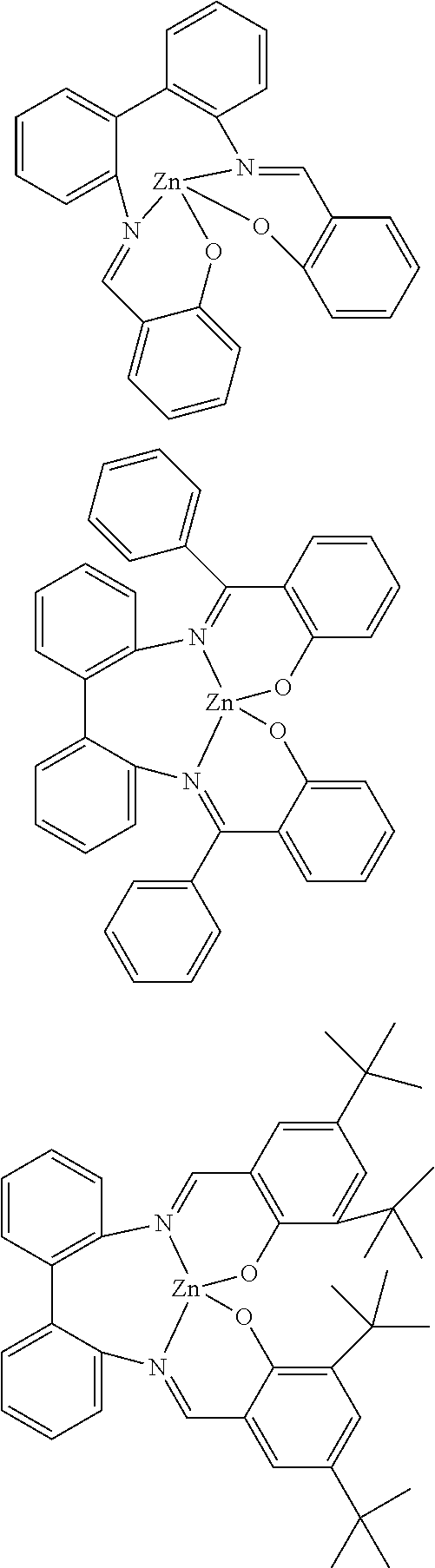


- 1. The compounds of the invention have a very high photoluminescence quantum yield. When used in an organic electroluminescent device, this leads to excellent efficiencies.
- 2. The compounds of the invention, when used in an organic electroluminescent device, lead to very long lifetimes.
- 3. The compounds of the invention have very narrow spectra, which, when used in an organic electroluminescent device, leads to greater color purity.


| Ex. | Boromic ester/acid | Product | Yield |
| L2 |
 |
 |
36% |
| L3 |
 |
 |
28% |
| L4 |
 |
 |
32% |
| L5 |
 |
 |
33% |
| L6 |
 |
 |
30% |
| L7 |
 |
 |
28% |
| L8 |
 |
 |
34% |
| L9 |
 |
 |
37% |
| L10 |
 |
 |
25% |
| L11 |
 |
 |
36% |
| L12 |
 |
 |
29% |
| L13 |
 |
 |
30% |
| L14 |
 |
 |
23% |
| L15 |
 |
 |
26% |
| L16 |
 |
 |
39% |
| L17 |
 |
 |
37% |
| L18 |
 |
 |
31% |
| L19 |
 |
 |
28% |
| L20 |
 |
 |
43% |
| L21 |
 |
 |
45% |
| L22 |
 |
 |
37% |
| L23 |
 |
 |
34% |
| L24 |
 |
 |
30% |
| L25 |
 |
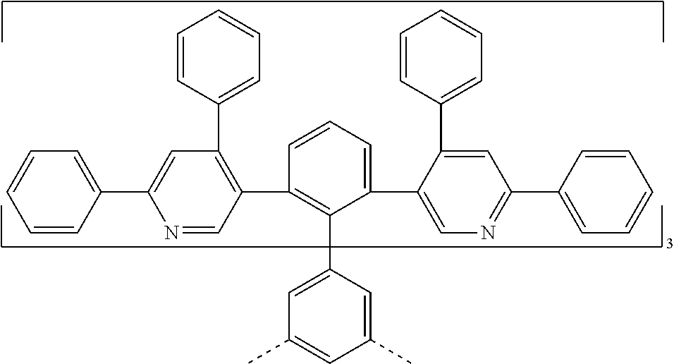 |
35% |
| L26 |
 |
 |
31% |
| L27 |
 |
 |
36% |
| L28 |
 |
 |
35% |
| L29 |
 |
 |
39% |
| L30 |
 |
 |
34% |
| L31 |
 |
 |
38% |
| L32 |
 |
 |
38% |
| L33 |
 |
 |
35% |
| L34 |
 |
 |
29% |

| Product | |||
| Reactants | Reaction time/temperture* | ||
| Ex. | variant | Hot extraction solvent* | Yield |
| Ir2(L2) | L2 |
 |
60% |
| Ir2(L3) | L3 |
 |
56% |
| Ir2(L4) | L4 | Ir2(L4) | 58% |
| DCM | |||
| Ir2(L5) | L5 | Ir2(L5) | 55% |
| DCM | |||
| Ir2(L6) | L6 | Ir2(L6) | 60% |
| toluene | |||
| Ir2(L7) | L7 | Ir2(L7) | 63% |
| DCM | |||
| Ir2(L8) | L8 | Ir2(L8) | 67% |
| o-Xylene | |||
| Ir2(L9) | L9 | Ir2(L9) | 61% |
| DCM | |||
| Ir2(L10) | L10 |
 |
34% |
| Ir2(L11) | L11 | Ir2(L11) | 58% |
| toluene | |||
| Ir2(L12) | L12 | Ir2(L12) | 62% |
| Ir2(L13) | L13 | Ir2(L13) | 55% |
| Ir2(L14) | L14 | Ir2(L14) | 59% |
| Butyl acetare | |||
| Ir2(L15) | L15 | Ir2(L15) | 60% |
| Ir2(L16) | L16 |
 |
72% |
| Ir2(L17) | L17 | Ir2(L17) | 64% |
| o-xylene | |||
| Ir2(L18) | L18 |
 |
44% |
| Ir2(L19) | L19 | Ir2(L19) | 41% |
| 2 h/260° C. | |||
| Ir2(L20) | L20 |
 |
54% |
| Ir2(L21) | L21 |
 |
69% |
| Ir2(L22) | L22 | Ir2(L22) | 66% |
| DCM | |||
| Ir2(L23) | L23 | Ir2(L23) | 63% |
| DCM | |||
| Ir2(L24) | L24 | Ir2(L24) | 58% |
| o-dichlorobenzene | |||
| Ir2(L25) | L25 | Ir2(L25) | 58% |
| o-xylene | |||
| Ir2(L26) | L26 | Ir2(L26) | 60% |
| Ir2(L27) | L27 | Ir2(L27) | 64% |
| DCM | |||
| Ir2(L28) | L28 | Ir2(L28) | 62% |
| DCM | |||
| Ir2(L29) | L29 | Ir2(L29) | 59% |
| Toluene | |||
| Ir2(L30) | L30 | Ir2(L34) | 57% |
| o-xylene | |||
| Ir2(L31) | L31 | Ir2(L31) | 64% |
| Ir2(L32) | L32 | Ir2(L32) | 49% |
| Ir2(L33) | L33 | Ir2(L33) | 58% |
| Ir2(L34) | L34 |
 |
36% |
| *if different | |||
| Rh-Ir(L1) | L1 1)10 mmol Ir(acac)3 [15635-87-7] 2) 10 mmol Rh(acac)3 [14284-92-5] |  | 14% |
| Rh-Ir(L16) | L16 1)10 mmol Ir(acac)3 [15635-87-7] 2) 10 mmol Rh(acac)3 [14284-92-5] |  | 17% |
D: Functionalization of the Metal Complexes
1) Halogenation of the Iridium Complexes:

| Reactants | |||
| Ex. | variant | Product | Yield |
| Ir2(L3-Br6) | Ir2(L3) |  | 95% |
| Ir2(L6-6Br) | Ir2(L6) |  | 93% |
| Ir2(L8-6Br) | Ir2(L8) |  | 97% |
| Ir2(L10-6Br) | Ir2(L10) |  | 96% |
| Ir2(L11-6Br) | Ir2(L11) |  | 96% |
| Ir2(L16-6Br) | Ir2(L16) |  | 94% |
| Ir2(L21-6Br) | Ir2(L21) |  | 95% |
| Ir2(L26-6Br) | Ir2(L26) |  | 96 |
2) Suzuki Coupling with the Brominated Iridium Complexes:
Variant a, Biphasic Reaction Mixture:

Variant B:
| Reactants | Product | ||
| Ex. | Variant | Hot extraction solvent | Yield |
| Ir22 | Ir(L1-6Br) 912844-88-4 B, then A, then debromination with hydrazine hydrate |  | 61% |
| Ir23 | Ir(L1-6Br) 888330-89-0 B |  | 55% |
| Ir24 | Ir2(L3-Br6) 1257248-43-3 B, then A, then debromination with hydrazine hydrate |  | 59% |
| Ir25 | Ir2(L6-6Br) 1126522-69-7 B, then A, then debromination with hydrazine hydrate |  | 52% |
| Ir26 | Ir2(L8-6Br) 80042-13-4 B, then A, then debromination with hydrazine hydrate |  | 60% |
| Ir27 | Ir2(L10-6Br) 627526-15-2 B |  | 53% |
| Ir28 | Ir2(L11-6Br) 84110-40-7 A S-Phos/ Pd(ac)2 2/1 |  | 49% |
| Ir29 | Ir2(L16-6Br) 796071-96-0 B, then A, then debromination with hydrazine hydrate |  | 59% |
| Ir210 | Ir2(L21-6Br) 4688-76-0 B |  | 54% |
| Ir211 | Ir2(L26-6Br) 610787-99-0 B |  | 46% |
Thermal and Photophysical Properties and Oxidation and Reduction Potentials
| TABLE 1 | |||||
| PL- | |||||
| max | Therm. | ||||
| [nm]. | stability | ||||
| HOMO | FWHM | PLQE | Decay time | Photochem. | |
| Complex | [eV] | [nm] | Solvent | τ [μs] | stab. |
| Comparative examples, for structures | |
| see device examples, table 2 | |
| Ref1 | −5.10 | 509 | 0.97 | 1.3 | decomp. |
| IrPPy | 67 | toluene | decomp. | ||
| Ref2 | −5.12 | 520 | 0.98 | 1.6 | no decomp. |
| 64 | toluene | no decomp. | |||
| Inventive examples | |
| Ir2(L1) | −5.00 | 519 | 0.98 | 1.2 | no decomp. |
| 60 | toluene | no decomp. | |||
| Ir2(L21) | −5.21 | 537 | 0.96 | 1.2 | no decomp. |
| 67 | toluene | no decomp. | |||
| Ir22 | −5.03 | 521 | 0.98 | 1.1 | no decomp. |
| 56 | toluene | no decomp. | |||
| Ir23 | −5.05 | 520 | 0.97 | 1.2 | no decomp. |
| 55 | toluene | no decomp. | |||
| Legend: | |||||
| Therm. stab. (thermal stability): Storage in ampoules closed by fusion under reduced pressure, 7 days at 380° C. Visual assessment for color change/brown discoloration/ashing and analysis by means of 1H NMR spectroscopy. | |||||
| Photo. stab. (photochemical stability): Irradiation of about 1 mmolar solutions in anhydrous C6D6 (degassed NMR tubes closed by fusion) with blue light (about 455 nm, 1.2 W Lumispot from Dialight Corporation, USA) at RT. | |||||
| PL-max.: Maximum of the PL spectrum in [nm] of a degassed about 10−5 molar solution at RT, excitation wavelength 370 nm, for solvent see PLQE column. | |||||
| FWHM: Half-height width of the PL spectrum in [nm] at RT; for solvent see PLQE column. | |||||
| PLQE: Abs. photoluminescence quantum efficiency of a degassed, about 10−5 molar solution in the solvent specified measured at RT as an absolute value via Ulbricht sphere. | |||||
| Decay time: | |||||
| T1 lifetime measurements were determined by time-correlated single photon counting of a degassed 10−5 molar solution in toluene at room temperature. | |||||
| HOMO, LUMO: in [eV] vs. vacuum, determined in dichloromethane solution (oxidation) or THF (reduction) with ferrocene as internal reference (−4.8 eV vs. vacuum). | |||||

| TABLE 2 |
| EML materials used |
 |
 |
 |
 |
 |
 |
 |
 |
 |
| TABLE 3 |
| HBL and ETL materials used |
 |
 |
| TABLE 4 |
| EML mixtures of the OLED components examined |
| Matrix A | Co-matrix B | Co-dopant C | Dopant D |
| Ex. | material | % | material | % | material | % | material | % |
| red |
| VR1 | A-2 | 30 | B-1 | 47 | G-1 | 17 | R-1 | 6 |
| VR2 | A-2 | 30 | B-1 | 34 | G-1 | 30 | R-2 | 6 |
| ER1 | A-2 | 30 | B-1 | 47 | G-1 | 17 | Ir2(L14) | 6 |
| ER2 | A-2 | 30 | B-1 | 34 | G-1 | 30 | Ir2(L14) | 6 |
| ER3 | A-2 | 30 | B-1 | 34 | G-1 | 28 | Ir27 | 8 |
| green - yellow |
| VG1 | A-2 | 20 | B-1 | 60 | — | — | G1 | 20 |
| VG2 | A-2 | 20 | B-1 | 60 | — | — | G2 | 20 |
| EG1 | A-2 | 20 | B-1 | 60 | — | — | Ir2(L6) | 20 |
| EG2 | A-2 | 20 | B-1 | 60 | — | — | Ir2(L11) | 20 |
| EG3 | A-2 | 20 | B-1 | 60 | — | — | Ir22 | 20 |
| EG4 | A-2 | 20 | B-1 | 60 | — | — | Ir23 | 20 |
| EG5 | A-2 | 20 | B-1 | 60 | — | — | Ir29 | 20 |
| EG6 | A-1 | 20 | B-1 | 60 | — | — | Ir211 | 20 |
| TABLE 5 |
| Structure of the OLED components examined |
| HIL | HTL | EML | HBL | ETL | |
| (thick- | (thick- | thick- | (thick- | (thick- | |
| Ex. | ness) | ness) | ness | ness) | ness) |
| red |
| VR1 | PEDOT | HTL2 | 60 nm | ETM-1 | ETM-1 (50%):ETM-2 |
| (60 nm) | (20 nm) | (10 nm) | (50%) (40 nm) | ||
| VR2 | PEDOT | HTL2 | 60 nm | ETM-1 | ETM-1 (50%):ETM-2 |
| (60 nm) | (20 nm) | (10 nm) | (50%) (40 nm) | ||
| ER1 | PEDOT | HTL2 | 60 nm | ETM-1 | ETM-1 (50%):ETM-2 |
| (60 nm) | (20 nm) | (10 nm) | (50%) (40 nm) | ||
| ER2 | PEDOT | HTL2 | 60 nm | ETM-1 | ETM-1 (50%):ETM-2 |
| (60 nm) | (20 nm) | (10 nm) | (50%) (40 nm) | ||
| ER3 | PEDOT | HTL2 | 60 nm | ETM-1 | ETM-1 (50%):ETM-2 |
| (60 nm) | (20 nm) | (10 nm) | (50%) (40 nm) |
| yellow - green |
| VG1 | PEDOT | HTL2 | 60 nm | ETM-1 | ETM-1 (50%):ETM-2 |
| (60 nm) | (20 nm) | (10 nm) | (50%) (40 nm) | ||
| VG2 | PEDOT | HTL2 | 60 nm | ETM-1 | ETM-1 (50%):ETM-2 |
| (60 nm) | (20 nm) | (10 nm) | (50%) (40 nm) | ||
| EG1 | PEDOT | HTL2 | 60 nm | ETM-1 | ETM-1 (50%):ETM-2 |
| (60 nm) | (20 nm) | (10 nm) | (50%) (40 nm) | ||
| EG2 | PEDOT | HTL2 | 60 nm | ETM-1 | ETM-1 (50%):ETM-2 |
| (60 nm) | (20 nm) | (10 nm) | (50%) (40 nm) | ||
| EG3 | PEDOT | HTL2 | 60 nm | ETM-1 | ETM-1 (50%):ETM-2 |
| (60 nm) | (20 nm) | (10 nm) | (50%) (40 nm) | ||
| EG4 | PEDOT | HTL2 | 60 nm | ETM-1 | ETM-1 (50%):ETM-2 |
| (60 nm) | (20 nm) | (10 nm) | (50%) (40 nm) | ||
| EG5 | PEDOT | HTL2 | 60 nm | ETM-1 | ETM-1 (50 %):ETM-2 |
| (60 nm) | (20 nm) | (10 nm) | (50%) (40 nm) | ||
| EG6 | PEDOT | HTL2 | 60 nm | ETM-1 | ETM-1 (50%):ETM-2 |
| (60 nm) | (20 nm) | (10 nm) | (50%) (40 nm) | ||
| TABLE 6 |
| Results for solution-processed OLEDs (measured at a |
| brightness of 1000 cd/m2) |
| red |
| EQE | LT90 | |||||
| Ex. | [%] | CIE x | CIE y | @60 mA/cm2 | ||
| VR1 | 16.2 | 0.66 | 0.34 | 276 | ||
| VR2 | 18.2 | 0.64 | 0.36 | 298 | ||
| ER1 | 19.6 | 0.66 | 0.34 | 329 | ||
| ER2 | 19.9 | 0.66 | 0.34 | 323 | ||
| ER3 | 19.8 | 0.65 | 0.35 | 305 | ||
| yellow-green |
| EQE | LT90 | |||||
| Ex. | [%] | CIE x | CIE y | @1000 cd/m2 | ||
| VG1 | 19.9 | 0.32 | 0.63 | 20000 | ||
| VG2 | 21.5 | 0.32 | 0.65 | 28000 | ||
| EG1 | 19.5 | 0.35 | 0.61 | 34000 | ||
| EG2 | 21.8 | 0.48 | 0.50 | 49000 | ||
| EG3 | 21.9 | 0.32 | 0.64 | 30000 | ||
| EG4 | 21.7 | 0.32 | 0.64 | 31000 | ||
| EG5 | 20.5 | 0.38 | 0.59 | 24000 | ||
| EG6 | 19.4 | 0.51 | 0.48 | 52000 | ||
Claims (17)


Applications Claiming Priority (4)
| Application Number | Priority Date | Filing Date | Title |
|---|---|---|---|
| EP16193610 | 2016-10-13 | ||
| EP16193610 | 2016-10-13 | ||
| EP16193610.9 | 2016-10-13 | ||
| PCT/EP2017/075737 WO2018069273A1 (en) | 2016-10-13 | 2017-10-10 | Metal complexes |
Publications (2)
| Publication Number | Publication Date |
|---|---|
| US20190252628A1 US20190252628A1 (en) | 2019-08-15 |
| US11145828B2 true US11145828B2 (en) | 2021-10-12 |
Family
ID=57133048
Family Applications (1)
| Application Number | Title | Priority Date | Filing Date |
|---|---|---|---|
| US16/342,082 Active 2038-09-28 US11145828B2 (en) | 2016-10-13 | 2017-10-10 | Metal complexes |
Country Status (6)
| Country | Link |
|---|---|
| US (1) | US11145828B2 (en) |
| EP (1) | EP3526226B1 (en) |
| JP (1) | JP7023946B2 (en) |
| KR (1) | KR102472249B1 (en) |
| CN (1) | CN109790192A (en) |
| WO (1) | WO2018069273A1 (en) |
Families Citing this family (47)
| Publication number | Priority date | Publication date | Assignee | Title |
|---|---|---|---|---|
| TW201817738A (en) | 2016-07-25 | 2018-05-16 | 德商麥克專利有限公司 | Metal complexes |
| TWI780134B (en) * | 2017-03-29 | 2022-10-11 | 德商麥克專利有限公司 | Aromatic compounds |
| TWI776926B (en) | 2017-07-25 | 2022-09-11 | 德商麥克專利有限公司 | Metal complexes |
| WO2020053150A1 (en) | 2018-09-12 | 2020-03-19 | Merck Patent Gmbh | Materials for organic electroluminescent devices |
| TWI826522B (en) | 2018-09-12 | 2023-12-21 | 德商麥克專利有限公司 | Electroluminescent devices |
| TW202030902A (en) | 2018-09-12 | 2020-08-16 | 德商麥克專利有限公司 | Electroluminescent devices |
| CN112771024A (en) | 2018-09-27 | 2021-05-07 | 默克专利有限公司 | Process for preparing sterically hindered nitrogen-containing heteroaromatics |
| CN112739795A (en) | 2018-09-27 | 2021-04-30 | 默克专利有限公司 | Compounds useful as active compounds in organic electronic devices |
| JP2022506382A (en) | 2018-11-05 | 2022-01-17 | メルク パテント ゲーエムベーハー | Compounds that can be used in organic electronic devices |
| EP3880657A1 (en) | 2018-11-14 | 2021-09-22 | Merck Patent GmbH | Compounds that can be used for producing an organic electronic device |
| US20220127286A1 (en) | 2019-03-04 | 2022-04-28 | Merck Patent Gmbh | Ligands for nano-sized materials |
| TW202104238A (en) | 2019-04-11 | 2021-02-01 | 德商麥克專利有限公司 | Materials for organic electroluminescent devices |
| US20220259238A1 (en) | 2019-07-22 | 2022-08-18 | Merck Patent Gmbh | Method for producing ortho-metallated metal compounds |
| CN114630831A (en) | 2019-10-25 | 2022-06-14 | 默克专利有限公司 | Compounds useful in organic electronic devices |
| KR20220092590A (en) | 2019-11-04 | 2022-07-01 | 메르크 파텐트 게엠베하 | Materials for organic electroluminescent devices |
| TW202134252A (en) | 2019-11-12 | 2021-09-16 | 德商麥克專利有限公司 | Materials for organic electroluminescent devices |
| TW202136181A (en) | 2019-12-04 | 2021-10-01 | 德商麥克專利有限公司 | Materials for organic electroluminescent devices |
| CN114787169A (en) | 2019-12-18 | 2022-07-22 | 默克专利有限公司 | Aromatic compound for organic electroluminescent device |
| US20230104248A1 (en) | 2019-12-19 | 2023-04-06 | Merck Patent Gmbh | Polycyclic compounds for organic electroluminescent devices |
| KR20220133937A (en) | 2020-01-29 | 2022-10-05 | 메르크 파텐트 게엠베하 | Benzimidazole derivatives |
| EP4110884A1 (en) | 2020-02-25 | 2023-01-04 | Merck Patent GmbH | Use of heterocyclic compounds in an organic electronic device |
| CN115244728A (en) | 2020-03-02 | 2022-10-25 | 默克专利有限公司 | Use of sulfone compounds in organic electronic devices |
| WO2021185712A1 (en) | 2020-03-17 | 2021-09-23 | Merck Patent Gmbh | Heteroaromatic compounds for organic electroluminescent devices |
| EP4122028A1 (en) | 2020-03-17 | 2023-01-25 | Merck Patent GmbH | Heterocyclic compounds for organic electroluminescent devices |
| US20230337537A1 (en) | 2020-03-23 | 2023-10-19 | Merck Patent Gmbh | Materials for organic electroluminescent devices |
| WO2021191183A1 (en) | 2020-03-26 | 2021-09-30 | Merck Patent Gmbh | Cyclic compounds for organic electroluminescent devices |
| US20230183269A1 (en) | 2020-04-06 | 2023-06-15 | Merck Patent Gmbh | Polycyclic compounds for organic electroluminescent devices |
| TW202210606A (en) | 2020-05-29 | 2022-03-16 | 德商麥克專利有限公司 | Organic electroluminescent device |
| EP4168397A1 (en) | 2020-06-18 | 2023-04-26 | Merck Patent GmbH | Indenoazanaphthalenes |
| EP4169082A1 (en) | 2020-06-23 | 2023-04-26 | Merck Patent GmbH | Method for producing a mixture |
| JP2023530915A (en) | 2020-06-29 | 2023-07-20 | メルク パテント ゲゼルシャフト ミット ベシュレンクテル ハフツング | Heterocyclic compounds for organic electroluminescent devices |
| KR20230029927A (en) | 2020-06-29 | 2023-03-03 | 메르크 파텐트 게엠베하 | Heteroaromatic compounds for organic electroluminescent devices |
| TW202229215A (en) | 2020-09-30 | 2022-08-01 | 德商麥克專利有限公司 | Compounds for structuring of functional layers of organic electroluminescent devices |
| TW202222748A (en) | 2020-09-30 | 2022-06-16 | 德商麥克專利有限公司 | Compounds usable for structuring of functional layers of organic electroluminescent devices |
| US20230389423A1 (en) | 2020-10-16 | 2023-11-30 | Merck Patent Gmbh | Heterocyclic compounds for organic electroluminescent devices |
| CN116406414A (en) | 2020-10-16 | 2023-07-07 | 默克专利有限公司 | Heteroatom-containing compounds for organic electroluminescent devices |
| EP4263543A1 (en) | 2020-12-18 | 2023-10-25 | Merck Patent GmbH | Nitrogenous compounds for organic electroluminescent devices |
| KR20230122094A (en) | 2020-12-18 | 2023-08-22 | 메르크 파텐트 게엠베하 | Indolo[3.2.1-JK]carbazole-6-carbonitrile derivatives as blue fluorescent emitters for use in OLEDs |
| US20240101560A1 (en) | 2020-12-18 | 2024-03-28 | Merck Patent Gmbh | Nitrogenous heteroaromatic compounds for organic electroluminescent devices |
| EP4330257A1 (en) | 2021-04-30 | 2024-03-06 | Merck Patent GmbH | Nitrogenous heterocyclic compounds for organic electroluminescent devices |
| CN117355364A (en) | 2021-05-21 | 2024-01-05 | 默克专利有限公司 | Method for continuously purifying at least one functional material and device for continuously purifying at least one functional material |
| WO2023041454A1 (en) | 2021-09-14 | 2023-03-23 | Merck Patent Gmbh | Boronic heterocyclic compounds for organic electroluminescent devices |
| WO2023072799A1 (en) | 2021-10-27 | 2023-05-04 | Merck Patent Gmbh | Boronic and nitrogenous heterocyclic compounds for organic electroluminescent devices |
| WO2023161167A1 (en) | 2022-02-23 | 2023-08-31 | Merck Patent Gmbh | Nitrogenous heterocycles for organic electroluminescent devices |
| WO2023161168A1 (en) | 2022-02-23 | 2023-08-31 | Merck Patent Gmbh | Aromatic hetreocycles for organic electroluminescent devices |
| WO2023247663A1 (en) | 2022-06-24 | 2023-12-28 | Merck Patent Gmbh | Composition for organic electronic devices |
| WO2023247662A1 (en) | 2022-06-24 | 2023-12-28 | Merck Patent Gmbh | Composition for organic electronic devices |
Citations (3)
| Publication number | Priority date | Publication date | Assignee | Title |
|---|---|---|---|---|
| WO2004081017A1 (en) | 2003-03-11 | 2004-09-23 | Covion Organic Semiconductors Gmbh | Metal complexes |
| US7332232B2 (en) | 2004-02-03 | 2008-02-19 | Universal Display Corporation | OLEDs utilizing multidentate ligand systems |
| WO2016124304A1 (en) | 2015-02-03 | 2016-08-11 | Merck Patent Gmbh | Metal complexes |
Family Cites Families (42)
| Publication number | Priority date | Publication date | Assignee | Title |
|---|---|---|---|---|
| JPH07133483A (en) | 1993-11-09 | 1995-05-23 | Shinko Electric Ind Co Ltd | Organic luminescent material for el element and el element |
| TW532048B (en) | 2000-03-27 | 2003-05-11 | Idemitsu Kosan Co | Organic electroluminescence element |
| DE10104426A1 (en) | 2001-02-01 | 2002-08-08 | Covion Organic Semiconductors | Process for the production of high-purity, tris-ortho-metallated organo-iridium compounds |
| ITRM20020411A1 (en) | 2002-08-01 | 2004-02-02 | Univ Roma La Sapienza | SPIROBIFLUORENE DERIVATIVES, THEIR PREPARATION AND USE. |
| DE10249723A1 (en) | 2002-10-25 | 2004-05-06 | Covion Organic Semiconductors Gmbh | Conjugated polymers containing arylamine units, their preparation and use |
| KR101030158B1 (en) | 2002-12-23 | 2011-04-18 | 메르크 파텐트 게엠베하 | Organic electroluminescent element |
| JP4411851B2 (en) | 2003-03-19 | 2010-02-10 | コニカミノルタホールディングス株式会社 | Organic electroluminescence device |
| DE10314102A1 (en) | 2003-03-27 | 2004-10-14 | Covion Organic Semiconductors Gmbh | Process for the production of high-purity organo-iridium compounds |
| EP2281861A3 (en) | 2003-04-15 | 2012-03-28 | Merck Patent GmbH | Mixture of organic emission-enabled semiconductors and matrix materials, use of same and electronic components containing same |
| US7326475B2 (en) | 2003-04-23 | 2008-02-05 | Konica Minolta Holdings, Inc. | Material for organic electroluminescent device, organic electroluminescent device, illuminating device and display |
| US7795801B2 (en) | 2003-09-30 | 2010-09-14 | Konica Minolta Holdings, Inc. | Organic electroluminescent element, illuminator, display and compound |
| US7790890B2 (en) | 2004-03-31 | 2010-09-07 | Konica Minolta Holdings, Inc. | Organic electroluminescence element material, organic electroluminescence element, display device and illumination device |
| DE102004023277A1 (en) | 2004-05-11 | 2005-12-01 | Covion Organic Semiconductors Gmbh | New material mixtures for electroluminescence |
| JP4862248B2 (en) | 2004-06-04 | 2012-01-25 | コニカミノルタホールディングス株式会社 | Organic electroluminescence element, lighting device and display device |
| ITRM20040352A1 (en) | 2004-07-15 | 2004-10-15 | Univ Roma La Sapienza | OLIGOMERIC DERIVATIVES OF SPIROBIFLUORENE, THEIR PREPARATION AND THEIR USE. |
| DE102004034517A1 (en) * | 2004-07-16 | 2006-02-16 | Covion Organic Semiconductors Gmbh | metal complexes |
| JP5242380B2 (en) | 2005-05-03 | 2013-07-24 | メルク パテント ゲーエムベーハー | Organic electroluminescence device |
| JP4593631B2 (en) | 2005-12-01 | 2010-12-08 | 新日鐵化学株式会社 | Compound for organic electroluminescence device and organic electroluminescence device |
| DE102006025777A1 (en) | 2006-05-31 | 2007-12-06 | Merck Patent Gmbh | New materials for organic electroluminescent devices |
| JP4388590B2 (en) | 2006-11-09 | 2009-12-24 | 新日鐵化学株式会社 | Compound for organic electroluminescence device and organic electroluminescence device |
| DE102007002714A1 (en) | 2007-01-18 | 2008-07-31 | Merck Patent Gmbh | New materials for organic electroluminescent devices |
| DE102007053771A1 (en) | 2007-11-12 | 2009-05-14 | Merck Patent Gmbh | Organic electroluminescent devices |
| US7862908B2 (en) | 2007-11-26 | 2011-01-04 | National Tsing Hua University | Conjugated compounds containing hydroindoloacridine structural elements, and their use |
| US8221905B2 (en) | 2007-12-28 | 2012-07-17 | Universal Display Corporation | Carbazole-containing materials in phosphorescent light emitting diodes |
| JP5357150B2 (en) | 2008-06-05 | 2013-12-04 | 出光興産株式会社 | Halogen compound, polycyclic compound, and organic electroluminescence device using the same |
| DE102008033943A1 (en) | 2008-07-18 | 2010-01-21 | Merck Patent Gmbh | New materials for organic electroluminescent devices |
| DE102008036982A1 (en) | 2008-08-08 | 2010-02-11 | Merck Patent Gmbh | Organic electroluminescent device |
| KR101506919B1 (en) | 2008-10-31 | 2015-03-30 | 롬엔드하스전자재료코리아유한회사 | Novel compounds for organic electronic material and organic electronic device using the same |
| DE102008056688A1 (en) | 2008-11-11 | 2010-05-12 | Merck Patent Gmbh | Materials for organic electroluminescent devices |
| JP5701766B2 (en) | 2008-11-11 | 2015-04-15 | メルク パテント ゲーエムベーハー | Organic electroluminescent device |
| CN106084187A (en) | 2009-02-27 | 2016-11-09 | 默克专利有限公司 | Polymer, crosslinked polymer and the electroluminescent device comprising described polymer |
| DE102009014513A1 (en) | 2009-03-23 | 2010-09-30 | Merck Patent Gmbh | Organic electroluminescent device |
| DE102009023155A1 (en) | 2009-05-29 | 2010-12-02 | Merck Patent Gmbh | Materials for organic electroluminescent devices |
| DE102009031021A1 (en) | 2009-06-30 | 2011-01-05 | Merck Patent Gmbh | Materials for organic electroluminescent devices |
| DE102009048791A1 (en) | 2009-10-08 | 2011-04-14 | Merck Patent Gmbh | Materials for organic electroluminescent devices |
| DE102010005697A1 (en) | 2010-01-25 | 2011-07-28 | Merck Patent GmbH, 64293 | Connections for electronic devices |
| CN104245785B (en) | 2012-04-17 | 2018-05-25 | 默克专利有限公司 | Crosslinkable and crosslinked polymer, Its Preparation Method And Use |
| KR102141345B1 (en) * | 2012-08-09 | 2020-08-05 | 메르크 파텐트 게엠베하 | Light emitting compounds |
| JP6486830B2 (en) | 2012-12-18 | 2019-03-20 | メルク パテント ゲーエムベーハー | Organic electroluminescent device |
| KR102048555B1 (en) * | 2013-04-17 | 2019-11-26 | 덕산네오룩스 주식회사 | Compound for organic electronic element, organic electronic element using the same, and an electronic device thereof |
| WO2015169412A1 (en) | 2014-05-05 | 2015-11-12 | Merck Patent Gmbh | Materials for organic light emitting devices |
| EP3341385B1 (en) | 2015-08-25 | 2020-03-11 | Merck Patent GmbH | Metal complexes |
-
2017
- 2017-10-10 CN CN201780059561.0A patent/CN109790192A/en active Pending
- 2017-10-10 EP EP17788158.8A patent/EP3526226B1/en active Active
- 2017-10-10 KR KR1020197013544A patent/KR102472249B1/en active IP Right Grant
- 2017-10-10 JP JP2019519992A patent/JP7023946B2/en active Active
- 2017-10-10 US US16/342,082 patent/US11145828B2/en active Active
- 2017-10-10 WO PCT/EP2017/075737 patent/WO2018069273A1/en unknown
Patent Citations (5)
| Publication number | Priority date | Publication date | Assignee | Title |
|---|---|---|---|---|
| WO2004081017A1 (en) | 2003-03-11 | 2004-09-23 | Covion Organic Semiconductors Gmbh | Metal complexes |
| US20060220004A1 (en) | 2003-03-11 | 2006-10-05 | Covion Organic Semiconductors Gmbh | Metal complexes |
| US7332232B2 (en) | 2004-02-03 | 2008-02-19 | Universal Display Corporation | OLEDs utilizing multidentate ligand systems |
| WO2016124304A1 (en) | 2015-02-03 | 2016-08-11 | Merck Patent Gmbh | Metal complexes |
| US20180026209A1 (en) | 2015-02-03 | 2018-01-25 | Merck Patent Gmbh | Metal Complexes |
Non-Patent Citations (3)
| Title |
|---|
| Gamez et al, The new multi-directional polydentate ligand 2,4,6-(di-pyridin-2-yl-amino)-[1,3,5]triazine (dpyatriz) can discriminate between Zn(II) and Co(II) nitrate, Polyhedron, vol. 22, Issue 1, pp. 205-210, Jan. 2003. * |
| International Search Report dated Jan. 18, 2018 in International Application No. PCT/EP2017/075737 (2 pages). |
| Maity et al, Di- and Trinuclear Iridium(III) Complexes with Poly-Mesoionic Carbenes Synthesized through Selective Base-Dependent Metalation, Organometallics, vol. 34, Issue 12, pp. 3090-3096, 2015. * |
Also Published As
| Publication number | Publication date |
|---|---|
| EP3526226B1 (en) | 2020-07-22 |
| EP3526226A1 (en) | 2019-08-21 |
| JP7023946B2 (en) | 2022-02-22 |
| CN109790192A (en) | 2019-05-21 |
| KR20190061077A (en) | 2019-06-04 |
| JP2019537568A (en) | 2019-12-26 |
| US20190252628A1 (en) | 2019-08-15 |
| WO2018069273A1 (en) | 2018-04-19 |
| KR102472249B1 (en) | 2022-11-29 |
Similar Documents
| Publication | Publication Date | Title |
|---|---|---|
| US11145828B2 (en) | Metal complexes | |
| US11322696B2 (en) | Metal complexes | |
| US11917903B2 (en) | Metal complexes | |
| US11659763B2 (en) | Metal complexes | |
| US11535640B2 (en) | Metal complexes | |
| KR102464513B1 (en) | Binuclear metal complexes for use as emitters in organic electroluminescent devices | |
| US11437592B2 (en) | Dinuclear and oligonuclear metal complexes containing tripodal bidentate part ligands and their use in electronic devices | |
| US11430962B2 (en) | Binuclear metal complexes and electronic devices, in particular organic electroluminescent devices containing said metal complexes | |
| US11713332B2 (en) | Metal complexes | |
| US11031562B2 (en) | Metal complexes | |
| US9831448B2 (en) | Metal complexes | |
| US11800787B2 (en) | Metal complexes | |
| US10103340B2 (en) | Metal complexes | |
| US9847499B2 (en) | Metal complexes | |
| US9831446B2 (en) | Metal complexes | |
| US20130112920A1 (en) | Metal complexes | |
| US20150333280A1 (en) | Metal Complexes | |
| US20150318498A1 (en) | Metal Complexes | |
| US20170309832A1 (en) | Metal complexes | |
| US20150349277A1 (en) | Metal complexes | |
| US20190280220A1 (en) | Metal complexes | |
| US20230056324A1 (en) | Metal complexes | |
| US20220209141A1 (en) | Metal complexes |
Legal Events
| Date | Code | Title | Description |
|---|---|---|---|
| FEPP | Fee payment procedure |
Free format text: ENTITY STATUS SET TO UNDISCOUNTED (ORIGINAL EVENT CODE: BIG.); ENTITY STATUS OF PATENT OWNER: LARGE ENTITY |
|
| AS | Assignment |
Owner name: MERCK PATENT GMBH, GERMANY Free format text: ASSIGNMENT OF ASSIGNORS INTEREST;ASSIGNORS:STOESSEL, PHILIPP;KOENEN, NILS;EHRENREICH, CHRISTIAN;REEL/FRAME:049751/0160 Effective date: 20190401 |
|
| STPP | Information on status: patent application and granting procedure in general |
Free format text: DOCKETED NEW CASE - READY FOR EXAMINATION |
|
| STPP | Information on status: patent application and granting procedure in general |
Free format text: NOTICE OF ALLOWANCE MAILED -- APPLICATION RECEIVED IN OFFICE OF PUBLICATIONS |
|
| STPP | Information on status: patent application and granting procedure in general |
Free format text: PUBLICATIONS -- ISSUE FEE PAYMENT RECEIVED |
|
| STPP | Information on status: patent application and granting procedure in general |
Free format text: PUBLICATIONS -- ISSUE FEE PAYMENT VERIFIED |
|
| STCF | Information on status: patent grant |
Free format text: PATENTED CASE |
|
| AS | Assignment |
Owner name: UDC IRELAND LIMITED, IRELAND Free format text: ASSIGNMENT OF ASSIGNORS INTEREST;ASSIGNOR:MERCK PATENT GMBH;REEL/FRAME:064004/0725 Effective date: 20230502 |