US11140559B2 - Inter-network access management for shared spectrum systems - Google Patents
Inter-network access management for shared spectrum systems Download PDFInfo
- Publication number
- US11140559B2 US11140559B2 US16/732,190 US201916732190A US11140559B2 US 11140559 B2 US11140559 B2 US 11140559B2 US 201916732190 A US201916732190 A US 201916732190A US 11140559 B2 US11140559 B2 US 11140559B2
- Authority
- US
- United States
- Prior art keywords
- network entity
- resources
- transmission power
- coordination
- data transmission
- Prior art date
- Legal status (The legal status is an assumption and is not a legal conclusion. Google has not performed a legal analysis and makes no representation as to the accuracy of the status listed.)
- Active
Links
- 238000001228 spectrum Methods 0.000 title claims abstract description 61
- 230000005540 biological transmission Effects 0.000 claims abstract description 166
- 238000000034 method Methods 0.000 claims abstract description 66
- 238000004891 communication Methods 0.000 claims abstract description 46
- 230000004044 response Effects 0.000 claims abstract description 40
- 230000003247 decreasing effect Effects 0.000 claims description 3
- 230000006870 function Effects 0.000 description 46
- 238000012545 processing Methods 0.000 description 26
- 230000008569 process Effects 0.000 description 13
- 230000003993 interaction Effects 0.000 description 12
- 238000001514 detection method Methods 0.000 description 9
- 230000002452 interceptive effect Effects 0.000 description 6
- 230000011664 signaling Effects 0.000 description 6
- 238000007726 management method Methods 0.000 description 4
- 238000005516 engineering process Methods 0.000 description 3
- 238000002108 rapid electrokinetic patterning Methods 0.000 description 3
- 101100172132 Mus musculus Eif3a gene Proteins 0.000 description 2
- 230000033228 biological regulation Effects 0.000 description 2
- 238000004590 computer program Methods 0.000 description 2
- 230000001276 controlling effect Effects 0.000 description 2
- 125000004122 cyclic group Chemical group 0.000 description 2
- 238000010586 diagram Methods 0.000 description 2
- 238000001914 filtration Methods 0.000 description 2
- 230000000670 limiting effect Effects 0.000 description 2
- 238000013507 mapping Methods 0.000 description 2
- 238000012986 modification Methods 0.000 description 2
- 230000004048 modification Effects 0.000 description 2
- 230000003287 optical effect Effects 0.000 description 2
- 230000002441 reversible effect Effects 0.000 description 2
- 230000006978 adaptation Effects 0.000 description 1
- 230000002411 adverse Effects 0.000 description 1
- 239000000969 carrier Substances 0.000 description 1
- 230000010267 cellular communication Effects 0.000 description 1
- 238000011161 development Methods 0.000 description 1
- 230000009977 dual effect Effects 0.000 description 1
- 239000000284 extract Substances 0.000 description 1
- 230000006872 improvement Effects 0.000 description 1
- 238000003780 insertion Methods 0.000 description 1
- 230000037431 insertion Effects 0.000 description 1
- 230000001788 irregular Effects 0.000 description 1
- 239000004973 liquid crystal related substance Substances 0.000 description 1
- 230000007774 longterm Effects 0.000 description 1
- 239000011159 matrix material Substances 0.000 description 1
- 238000005259 measurement Methods 0.000 description 1
- 238000012544 monitoring process Methods 0.000 description 1
- 230000001105 regulatory effect Effects 0.000 description 1
- 238000009877 rendering Methods 0.000 description 1
- 238000013468 resource allocation Methods 0.000 description 1
- 238000010408 sweeping Methods 0.000 description 1
- 238000012549 training Methods 0.000 description 1
- 230000001960 triggered effect Effects 0.000 description 1
Images


Classifications
-
- H—ELECTRICITY
- H04—ELECTRIC COMMUNICATION TECHNIQUE
- H04W—WIRELESS COMMUNICATION NETWORKS
- H04W16/00—Network planning, e.g. coverage or traffic planning tools; Network deployment, e.g. resource partitioning or cells structures
- H04W16/14—Spectrum sharing arrangements between different networks
-
- H—ELECTRICITY
- H04—ELECTRIC COMMUNICATION TECHNIQUE
- H04W—WIRELESS COMMUNICATION NETWORKS
- H04W72/00—Local resource management
- H04W72/12—Wireless traffic scheduling
- H04W72/1215—Wireless traffic scheduling for collaboration of different radio technologies
-
- H—ELECTRICITY
- H04—ELECTRIC COMMUNICATION TECHNIQUE
- H04W—WIRELESS COMMUNICATION NETWORKS
- H04W52/00—Power management, e.g. TPC [Transmission Power Control], power saving or power classes
- H04W52/04—TPC
-
- H—ELECTRICITY
- H04—ELECTRIC COMMUNICATION TECHNIQUE
- H04W—WIRELESS COMMUNICATION NETWORKS
- H04W52/00—Power management, e.g. TPC [Transmission Power Control], power saving or power classes
- H04W52/04—TPC
- H04W52/06—TPC algorithms
- H04W52/14—Separate analysis of uplink or downlink
- H04W52/143—Downlink power control
-
- H—ELECTRICITY
- H04—ELECTRIC COMMUNICATION TECHNIQUE
- H04W—WIRELESS COMMUNICATION NETWORKS
- H04W52/00—Power management, e.g. TPC [Transmission Power Control], power saving or power classes
- H04W52/04—TPC
- H04W52/18—TPC being performed according to specific parameters
- H04W52/24—TPC being performed according to specific parameters using SIR [Signal to Interference Ratio] or other wireless path parameters
- H04W52/243—TPC being performed according to specific parameters using SIR [Signal to Interference Ratio] or other wireless path parameters taking into account interferences
-
- H—ELECTRICITY
- H04—ELECTRIC COMMUNICATION TECHNIQUE
- H04W—WIRELESS COMMUNICATION NETWORKS
- H04W72/00—Local resource management
- H04W72/12—Wireless traffic scheduling
- H04W72/1263—Mapping of traffic onto schedule, e.g. scheduled allocation or multiplexing of flows
- H04W72/1273—Mapping of traffic onto schedule, e.g. scheduled allocation or multiplexing of flows of downlink data flows
-
- H—ELECTRICITY
- H04—ELECTRIC COMMUNICATION TECHNIQUE
- H04W—WIRELESS COMMUNICATION NETWORKS
- H04W74/00—Wireless channel access
- H04W74/08—Non-scheduled access, e.g. ALOHA
- H04W74/0808—Non-scheduled access, e.g. ALOHA using carrier sensing, e.g. carrier sense multiple access [CSMA]
Definitions
- the present application relates generally to wireless communication systems, more specifically, the present disclosure relates to inter-network access management in an shared spectrum wireless communication systems.
- CBRS band has a unique three-tiered access model, which includes incumbent (federal user, fixed satellite service), priority access licensees (PALs), and general authorized access (GAA) in descending order of priority [FCC 16-55].
- incumbent federal user, fixed satellite service
- PALs priority access licensees
- GAA general authorized access
- 5925-7125 MHz band and 5925-6425 MHz band are under consideration in US and EU, respectively, for unlicensed use. Regulation is expected to be finished in 2019-2020 time frame.
- 37-38.6 GHz band is expected to be opened.
- the present disclosure relates to inter-network access management in an advanced shared spectrum wireless communication system.
- a network entity in a wireless communication system of shared spectrum resources includes a transceiver configured to transmit, to a set of neighbor network entities in the wireless communication system, a coordination request message indicating an intended transmission power for a data transmission by the network entity; and to receive, from at least one of the set of neighbor network entities, a coordination response message in response to the coordination request message.
- the network entity also includes a processor operably connected to the transceiver.
- the processor is configured to determine resources of the shared spectrum resources to use for the data transmission based on the intended transmission power and the coordination response message.
- the transceiver is configured to transmit, to at least one terminal in a cell of the network entity, the data transmission based on the determined resources.
- a method for operating a network entity in a wireless communication system of shared spectrum resources includes transmitting, to a set of neighbor network entities in the wireless communication system, a coordination request message indicating an intended transmission power for a data transmission by the network entity; and receiving, from at least one of the set of neighbor network entities, a coordination response message in response to the coordination request message.
- the method further includes determining resources of the shared spectrum resources to use for the data transmission based on the intended transmission power and the coordination response message; and transmitting, to at least one terminal in a cell of the network entity, the data transmission based on the determined resources.
- Couple and its derivatives refer to any direct or indirect communication between two or more elements, whether or not those elements are in physical contact with one another.
- transmit and “communicate,” as well as derivatives thereof, encompass both direct and indirect communication.
- the term “or” is inclusive, meaning and/or.
- controller means any device, system or part thereof that controls at least one operation. Such a controller may be implemented in hardware or a combination of hardware and software and/or firmware. The functionality associated with any particular controller may be centralized or distributed, whether locally or remotely.
- phrases “at least one of,” when used with a list of items, means that different combinations of one or more of the listed items may be used, and only one item in the list may be needed.
- “at least one of: A, B, and C” includes any of the following combinations: A, B, C, A and B, A and C, B and C, and A and B and C.
- various functions described below can be implemented or supported by one or more computer programs, each of which is formed from computer readable program code and embodied in a computer readable medium.
- application and “program” refer to one or more computer programs, software components, sets of instructions, procedures, functions, objects, classes, instances, related data, or a portion thereof adapted for implementation in a suitable computer readable program code.
- computer readable program code includes any type of computer code, including source code, object code, and executable code.
- computer readable medium includes any type of medium capable of being accessed by a computer, such as read only memory (ROM), random access memory (RAM), a hard disk drive, a compact disc (CD), a digital video disc (DVD), or any other type of memory.
- ROM read only memory
- RAM random access memory
- CD compact disc
- DVD digital video disc
- a “non-transitory” computer readable medium excludes wired, wireless, optical, or other communication links that transport transitory electrical or other signals.
- a non-transitory computer readable medium includes media where data can be permanently stored and media where data can be stored and later overwritten, such as a rewritable optical disc or an erasable memory device.
- shared spectrum is used in an inclusive manner without the distinction on the shared spectrum and unlicensed spectrum and the term “shared spectrum” also includes not only the currently available spectrums but also spectrums that will be made available in the future. Thus, the term “shared spectrum” should not be interpreted as a limiting factor in determining the scope of the present disclosure.
- FIG. 1 illustrates an example wireless network according to embodiments of the present disclosure
- FIG. 2 illustrates an example network entity of a gNB according to embodiments of the present disclosure
- FIG. 3 illustrates an example UE according to embodiments of the present disclosure
- FIG. 4 illustrates an example transmitter structure using OFDM according to embodiments of the present disclosure
- FIG. 5 illustrates an example receiver structure using OFDM according to embodiments of the present disclosure
- FIG. 6 illustrates an example encoding process for a DCI format according to embodiments of the present disclosure
- FIG. 7 illustrates an example decoding process for a DCI format for use with a UE according to embodiments of the present disclosure
- FIG. 8 illustrates an example multiple base stations (BS) of different MNOs according to embodiments of the present disclosure
- FIG. 9 illustrates an example spectrum sharing according to embodiments of the present disclosure.
- FIG. 10 illustrates an example overall sharing framework according to embodiments of the present disclosure
- FIG. 11 illustrates a flowchart of a method for sharing framework according to embodiments of the present disclosure
- FIG. 12 illustrates an example coordination period according to embodiments of the present disclosure
- FIG. 13 illustrates an example DTP structure according to embodiments of the present disclosure
- FIG. 14 illustrates an example coordination message exchanges according to embodiments of the present disclosure
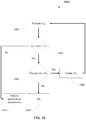
- FIG. 15 illustrates a flowchart of a method for determining the power adjustment for CP according to embodiments of the present disclosure
- FIG. 16 illustrates a flowchart of a method for deciding the C-REP response according to embodiments of the present disclosure
- FIG. 17 illustrates an example detection threshold function according to embodiments of the present disclosure
- FIG. 18 illustrates an example channel sensing for opportunistic data transmission according to embodiments of the present disclosure
- FIG. 19 illustrates a flowchart of a method for determining the opportunistic transmission according to embodiments of the present disclosure
- FIG. 20 illustrates an example spectrum sharing according to embodiments of the present disclosure.
- FIG. 21 illustrates an example of a method for operating a network entity in a wireless communication system of shared spectrum resources according to embodiments of the present disclosure.
- FIG. 1 through FIG. 21 discussed below, and the various embodiments used to describe the principles of the present disclosure in this patent document are by way of illustration only and should not be construed in any way to limit the scope of the disclosure. Those skilled in the art will understand that the principles of the present disclosure may be implemented in any suitably arranged system or device.
- FIGS. 1-3 describe various embodiments implemented in wireless communications systems and with the use of orthogonal frequency division multiplexing (OFDM) or orthogonal frequency division multiple access (OFDMA) communication techniques.
- OFDM orthogonal frequency division multiplexing
- OFDMA orthogonal frequency division multiple access
- FIG. 1 illustrates an example wireless network according to embodiments of the present disclosure.
- the embodiment of the wireless network shown in FIG. 1 is for illustration only. Other embodiments of the wireless network 100 could be used without departing from the scope of the present disclosure.
- the wireless network includes network entities including a gNB 101 , a gNB 102 , and a gNB 103 .
- the gNB 101 communicates with the gNB 102 and the gNB 103 .
- the gNB 101 also communicates with at least one network 130 , such as the Internet, a proprietary Internet Protocol (IP) network, or other data network.
- IP Internet Protocol
- the gNB 102 provides wireless broadband access to the network 130 for a first plurality of user equipments (UEs) within a coverage area 120 of the gNB 102 .
- the first plurality of UEs includes a UE 111 , which may be located in a small business (SB); a UE 112 , which may be located in an enterprise (E); a UE 113 , which may be located in a WiFi hotspot (HS); a UE 114 , which may be located in a first residence (R); a UE 115 , which may be located in a second residence (R); and a UE 116 , which may be a mobile device (M), such as a cell phone, a wireless laptop, a wireless PDA, or the like.
- M mobile device
- the gNB 103 provides wireless broadband access to the network 130 for a second plurality of UEs within a coverage area 125 of the gNB 103 .
- the second plurality of UEs includes the UE 115 and the UE 116 .
- one or more of the gNBs 101 - 103 may communicate with each other and with the UEs 111 - 116 using 5G, LTE, LTE-A, WiMAX, WiFi, or other wireless communication techniques.
- the term “network entity,” “base station,” or “BS” can refer to any component (or collection of components) configured to provide wireless access to a network, such as transmit point (TP), transmit-receive point (TRP), an enhanced base station (eNodeB or eNB), a 5G base station (gNB), a macrocell, a femtocell, a WiFi access point (AP), or other wirelessly enabled devices.
- Base stations may provide wireless access in accordance with one or more wireless communication protocols, e.g., 5G 3GPP new radio interface/access (NR), long term evolution (LTE), LTE advanced (LTE-A), high speed packet access (HSPA), Wi-Fi 802.11a/b/g/n/ac, etc.
- the terms “BS” and “TRP” are used interchangeably in this patent document to refer to network infrastructure components that provide wireless access to remote terminals.
- the term “user equipment” or “UE” can refer to any component such as “mobile station,” “subscriber station,” “remote terminal,” “wireless terminal,” “receive point,” or “user device.”
- the terms “user equipment” and “UE” are used in this patent document to refer to remote wireless equipment that wirelessly accesses a BS, whether the UE is a mobile device (such as a mobile telephone or smartphone) or is normally considered a stationary device (such as a desktop computer or vending machine).
- one or more of the UEs 111 - 116 include circuitry, programming, or a combination thereof, for reception reliability for data and control information in an advanced wireless communication system.
- one or more of the gNBs 101 - 103 includes circuitry, programming, or a combination thereof, for efficient inter-network access management for shared spectrum systems.
- FIG. 1 illustrates one example of a wireless network
- the wireless network could include any number of gNBs and any number of UEs in any suitable arrangement.
- the gNB 101 could communicate directly with any number of UEs and provide those UEs with wireless broadband access to the network 130 .
- each gNB 102 - 103 could communicate directly with the network 130 and provide UEs with direct wireless broadband access to the network 130 .
- the gNBs 101 , 102 , and/or 103 could provide access to other or additional external networks, such as external telephone networks or other types of data networks.
- FIG. 2 illustrates an example network entity of a gNB 102 according to embodiments of the present disclosure.
- the embodiment of the gNB 102 illustrated in FIG. 2 is for illustration only, and the gNBs 101 and 103 of FIG. 1 could have the same or similar configuration.
- gNBs come in a wide variety of configurations, and FIG. 2 does not limit the scope of the present disclosure to any particular implementation of a gNB.
- the gNB 102 includes multiple antennas 205 a - 205 n , multiple RF transceivers 210 a - 210 n , transmit (TX) processing circuitry 215 , and receive (RX) processing circuitry 220 .
- the gNB 102 also includes a controller/processor 225 , a memory 230 , and a backhaul or network interface 235 .
- the RF transceivers 210 a - 210 n receive, from the antennas 205 a - 205 n , incoming RF signals, such as signals transmitted by UEs in the network 100 .
- the RF transceivers 210 a - 210 n down-convert the incoming RF signals to generate IF or baseband signals.
- the IF or baseband signals are sent to the RX processing circuitry 220 , which generates processed baseband signals by filtering, decoding, and/or digitizing the baseband or IF signals.
- the RX processing circuitry 220 transmits the processed baseband signals to the controller/processor 225 for further processing.
- the TX processing circuitry 215 receives analog or digital data (such as voice data, web data, e-mail, or interactive video game data) from the controller/processor 225 .
- the TX processing circuitry 215 encodes, multiplexes, and/or digitizes the outgoing baseband data to generate processed baseband or IF signals.
- the RF transceivers 210 a - 210 n receive the outgoing processed baseband or IF signals from the TX processing circuitry 215 and up-converts the baseband or IF signals to RF signals that are transmitted via the antennas 205 a - 205 n.
- the controller/processor 225 can include one or more processors or other processing devices that control the overall operation of the gNB 102 .
- the controller/processor 225 could control the reception of forward channel signals and the transmission of reverse channel signals by the RF transceivers 210 a - 210 n , the RX processing circuitry 220 , and the TX processing circuitry 215 in accordance with well-known principles.
- the controller/processor 225 could support additional functions as well, such as more advanced wireless communication functions.
- the controller/processor 225 could support beam forming or directional routing operations in which outgoing signals from multiple antennas 205 a - 205 n are weighted differently to effectively steer the outgoing signals in a desired direction. Any of a wide variety of other functions could be supported in the gNB 102 by the controller/processor 225 .
- the controller/processor 225 is also capable of executing programs and other processes resident in the memory 230 , such as an OS.
- the controller/processor 225 can move data into or out of the memory 230 as required by an executing process.
- the controller/processor 225 is also coupled to the backhaul or network interface 235 .
- the backhaul or network interface 235 allows the gNB 102 to communicate with other devices or systems over a backhaul connection or over a network.
- the interface 235 could support communications over any suitable wired or wireless connection(s). For example, when the gNB 102 is implemented as part of a cellular communication system (such as one supporting 5G, LTE, or LTE-A), the interface 235 could allow the gNB 102 to communicate with other gNBs over a wired or wireless backhaul connection.
- the interface 235 could allow the gNB 102 to communicate over a wired or wireless local area network or over a wired or wireless connection to a larger network (such as the Internet).
- the interface 235 includes any suitable structure supporting communications over a wired or wireless connection, such as an Ethernet or RF transceiver.
- the memory 230 is coupled to the controller/processor 225 .
- Part of the memory 230 could include a RAM, and another part of the memory 230 could include a Flash memory or other ROM.
- FIG. 2 illustrates one example of the gNB 102
- the gNB 102 could include any number of each component shown in FIG. 2 .
- an network entity could include a number of interfaces 235
- the controller/processor 225 could support routing functions to route data between different network addresses.
- the gNB 102 while shown as including a single instance of TX processing circuitry 215 and a single instance of RX processing circuitry 220 , the gNB 102 could include multiple instances of each (such as one per RF transceiver).
- various components in FIG. 2 could be combined, further subdivided, or omitted and additional components could be added according to particular needs.
- FIG. 3 illustrates an example UE 116 according to embodiments of the present disclosure.
- the embodiment of the UE 116 illustrated in FIG. 3 is for illustration only, and the UEs 111 - 115 of FIG. 1 could have the same or similar configuration.
- UEs come in a wide variety of configurations, and FIG. 3 does not limit the scope of the present disclosure to any particular implementation of a UE.
- the UE 116 includes an antenna 305 , a radio frequency (RF) transceiver 310 , TX processing circuitry 315 , a microphone 320 , and receive (RX) processing circuitry 325 .
- the UE 116 also includes a speaker 330 , a processor 340 , an input/output (I/O) interface (IF) 345 , a touchscreen 350 , a display 355 , and a memory 360 .
- the memory 360 includes an operating system (OS) 361 and one or more applications 362 .
- OS operating system
- applications 362 one or more applications
- the RF transceiver 310 receives, from the antenna 305 , an incoming RF signal transmitted by a gNB of the network 100 .
- the RF transceiver 310 down-converts the incoming RF signal to generate an intermediate frequency (IF) or baseband signal.
- the IF or baseband signal is sent to the RX processing circuitry 325 , which generates a processed baseband signal by filtering, decoding, and/or digitizing the baseband or IF signal.
- the RX processing circuitry 325 transmits the processed baseband signal to the speaker 330 (such as for voice data) or to the processor 340 for further processing (such as for web browsing data).
- the TX processing circuitry 315 receives analog or digital voice data from the microphone 320 or other outgoing baseband data (such as web data, e-mail, or interactive video game data) from the processor 340 .
- the TX processing circuitry 315 encodes, multiplexes, and/or digitizes the outgoing baseband data to generate a processed baseband or IF signal.
- the RF transceiver 310 receives the outgoing processed baseband or IF signal from the TX processing circuitry 315 and up-converts the baseband or IF signal to an RF signal that is transmitted via the antenna 305 .
- the processor 340 can include one or more processors or other processing devices and execute the OS 361 stored in the memory 360 in order to control the overall operation of the UE 116 .
- the processor 340 could control the reception of forward channel signals and the transmission of reverse channel signals by the RF transceiver 310 , the RX processing circuitry 325 , and the TX processing circuitry 315 in accordance with well-known principles.
- the processor 340 includes at least one microprocessor or microcontroller.
- the processor 340 is also capable of executing other processes and programs resident in the memory 360 , such as processes for beam management.
- the processor 340 can move data into or out of the memory 360 as required by an executing process.
- the processor 340 is configured to execute the applications 362 based on the OS 361 or in response to signals received from gNBs or an operator.
- the processor 340 is also coupled to the I/O interface 345 , which provides the UE 116 with the ability to connect to other devices, such as laptop computers and handheld computers.
- the I/O interface 345 is the communication path between these accessories and the processor 340 .
- the processor 340 is also coupled to the touchscreen 350 and the display 355 .
- the operator of the UE 116 can use the touchscreen 350 to enter data into the UE 116 .
- the display 355 may be a liquid crystal display, light emitting diode display, or other display capable of rendering text and/or at least limited graphics, such as from web sites.
- the memory 360 is coupled to the processor 340 .
- Part of the memory 360 could include a random access memory (RAM), and another part of the memory 360 could include a Flash memory or other read-only memory (ROM).
- RAM random access memory
- ROM read-only memory
- FIG. 3 illustrates one example of the UE 116
- various changes may be made to FIG. 3 .
- various components in FIG. 3 could be combined, further subdivided, or omitted and additional components could be added according to particular needs.
- the processor 340 could be divided into multiple processors, such as one or more central processing units (CPUs) and one or more graphics processing units (GPUs).
- FIG. 3 illustrates the UE 116 configured as a mobile telephone or smartphone, UEs could be configured to operate as other types of mobile or stationary devices.
- the present disclosure relates generally to wireless communication systems and, more specifically, to reducing power consumption for a user equipment (UE) communicating with a base station and to transmissions to and receptions from a UE of physical downlink control channels (PDCCHs) for operation with dual connectivity.
- a communication system includes a downlink (DL) that refers to transmissions from a base station or one or more transmission points to UEs and an uplink (UL) that refers to transmissions from UEs to a base station or to one or more reception points.
- DL downlink
- UL uplink
- the 5G or pre-5G communication system is also called a “beyond 4G network” or a “post LTE system.”
- the 5G communication system is considered to be implemented in higher frequency (mmWave) bands, e.g., 60 GHz bands, so as to accomplish higher data rates.
- mmWave e.g., 60 GHz bands
- MIMO massive multiple-input multiple-output
- FD-MIMO full dimensional MIMO
- array antenna an analog beam forming, large scale antenna techniques are discussed in 5G communication systems.
- RANs cloud radio access networks
- D2D device-to-device
- wireless backhaul moving network
- CoMP coordinated multi-points
- a time unit for DL signaling or for UL signaling on a cell is referred to as a slot and can include one or more symbols.
- a symbol can also serve as an additional time unit.
- a frequency (or bandwidth (BW)) unit is referred to as a resource block (RB).
- One RB includes a number of sub-carriers (SCs).
- SCs sub-carriers
- a slot can include 14 symbols, have duration of 1 millisecond or 0.5 milliseconds, and an RB can have a BW of 180 kHz or 360 kHz and include 12 SCs with inter-SC spacing of 15 kHz or 30 kHz, respectively.
- DL signals include data signals conveying information content, control signals conveying DL control information (DCI) formats, and reference signals (RS) that are also known as pilot signals.
- a gNB can transmit data information (e.g., transport blocks) or DCI formats through respective physical DL shared channels (PDSCHs) or physical DL control channels (PDCCHs).
- a gNB can transmit one or more of multiple types of RS including channel state information RS (CSI-RS) and demodulation RS (DMRS).
- CSI-RS channel state information RS
- DMRS demodulation RS
- a CSI-RS is intended for UEs to measure channel state information (CSI) or to perform other measurements such as ones related to mobility support.
- a DMRS can be transmitted only in the BW of a respective PDCCH or PDSCH and a UE can use the DMRS to demodulate data or control information.
- UL signals also include data signals conveying information content, control signals conveying UL control information (UCI), and RS.
- a UE transmits data information (e.g., transport blocks) or UCI through a respective physical UL shared channel (PUSCH) or a physical UL control channel (PUCCH).
- PUSCH physical UL shared channel
- PUCCH physical UL control channel
- UCI includes hybrid automatic repeat request acknowledgement (HARQ-ACK) information, indicating correct or incorrect detection of data transport blocks (TBs) by a UE, scheduling request (SR) indicating whether a UE has data in the UE's buffer, and CSI reports enabling a gNB to select appropriate parameters to perform link adaptation for PDSCH or PDCCH transmissions to a UE.
- HARQ-ACK hybrid automatic repeat request acknowledgement
- SR scheduling request
- CSI reports enabling a gNB to select appropriate parameters to perform link adaptation for PDSCH or PDCCH transmissions to a UE.
- a CSI report from a UE can include a channel quality indicator (CQI) informing a gNB of a modulation and coding scheme (MCS) for the UE to detect a data TB with a predetermined block error rate (BLER), such as a 10% BLER, of a precoding matrix indicator (PMI) informing a gNB how to precode signaling to a UE, and of a rank indicator (RI) indicating a transmission rank for a PDSCH.
- UL RS includes DMRS and sounding RS (SRS). DMRS is transmitted only in a BW of a respective PUSCH or PUCCH transmission.
- a gNB can use a DMRS to demodulate information in a respective PUSCH or PUCCH.
- SRS is transmitted by a UE to provide a gNB with UL CSI and, for a TDD or a flexible duplex system, to also provide a PMI for DL transmissions.
- An UL DMRS or SRS transmission can be based, for example, on a transmission of a Zadoff-Chu (ZC) sequence or, in general, of a CAZAC sequence.
- ZC Zadoff-Chu
- DL transmissions and UL transmissions can be based on an orthogonal frequency division multiplexing (OFDM) waveform including a variant using DFT preceding that is known as DFT-spread-OFDM.
- OFDM orthogonal frequency division multiplexing
- FIG. 4 illustrates an example transmitter structure 400 using OFDM according to embodiments of the present disclosure.
- the transmitter structure 400 may be include in the gNB 102 or the UE 116 .
- An embodiment of the transmitter structure 400 shown in FIG. 4 is for illustration only.
- One or more of the components illustrated in FIG. 4 can be implemented in specialized circuitry configured to perform the noted functions or one or more of the components can be implemented by one or more processors executing instructions to perform the noted functions.
- Other embodiments are used without departing from the scope of the present disclosure.
- Information bits such as DCI bits or data bits 410 , are encoded by encoder 420 , rate matched to assigned time/frequency resources by rate matcher 430 and modulated by modulator 440 . Subsequently, modulated encoded symbols and DMRS or CSI-RS 450 are mapped to SCs 460 by SC mapping circuit 465 , an inverse fast Fourier transform (IFFT) is performed by filter 470 , a cyclic prefix (CP) is added by CP insertion circuit 480 , and a resulting signal is filtered by filter 490 and transmitted by an radio frequency (RF) circuit 495 .
- IFFT inverse fast Fourier transform
- CP cyclic prefix
- RF radio frequency
- FIG. 5 illustrates an example receiver structure 500 using OFDM according to embodiments of the present disclosure.
- the receiver structure 500 may be included in the gNB 102 or the UE 116 .
- An embodiment of the receiver structure 500 shown in FIG. 5 is for illustration only.
- One or more of the components illustrated in FIG. 5 can be implemented in specialized circuitry configured to perform the noted functions or one or more of the components can be implemented by one or more processors executing instructions to perform the noted functions. Other embodiments are used without departing from the scope of the present disclosure.
- a received signal 510 is filtered by filter 520 , a CP removal circuit removes a CP 530 , a filter 540 applies a fast Fourier transform (FFT), SCs de-mapping circuit 550 de-maps SCs selected by BW selector circuit 555 , received symbols are demodulated by a channel estimator and a demodulator circuit 560 , a rate de-matcher 570 restores a rate matching, and a decoder 580 decodes the resulting bits to provide information bits 590 .
- FFT fast Fourier transform
- a UE typically monitors multiple candidate locations for respective potential PDCCH transmissions to decode multiple candidate DCI formats in a slot.
- Monitoring a PDCCH candidates means receiving and decoding the PDCCH candidate according to DCI formats the UE is configured to receive.
- a DCI format includes cyclic redundancy check (CRC) bits in order for the UE to confirm a correct detection of the DCI format.
- CRC cyclic redundancy check
- a DCI format type is identified by a radio network temporary identifier (RNTI) that scrambles the CRC bits.
- the RNTI can be a cell RNTI (C-RNTI) and serves as a UE identifier.
- the RNTI can be an SI-RNTI.
- SI-RNTI system information
- RAR random-access response
- the RNTI can be an RA-RNTI.
- TC-RNTI temporary C-RNTI
- the RNTI can be a TPC-PUSCH-RNTI or a TPC-PUCCH-RNTI.
- Each RNTI type can be configured to a UE through higher-layer signaling such as RRC signaling.
- a DCI format scheduling PDSCH transmission to a UE is also referred to as DL DCI format or DL assignment while a DCI format scheduling PUSCH transmission from a UE is also referred to as UL DCI format or UL grant.
- a PDCCH transmission can be within a set of physical RBs (PRBs).
- a gNB can configure a UE one or more sets of PRBs, also referred to as control resource sets, for PDCCH receptions.
- a PDCCH transmission can be in control channel elements (CCEs) that are included in a control resource set.
- CCEs control channel elements
- a UE determines CCEs for a PDCCH reception based on a search space such as a UE-specific search space (USS) for PDCCH candidates with DCI format having CRC scrambled by a RNTI, such as a C-RNTI, that is configured to the UE by UE-specific RRC signaling for scheduling PDSCH reception or PUSCH transmission, and a common search space (CSS) for PDCCH candidates with DCI formats having CRC scrambled by other RNTIs.
- a set of CCEs that can be used for PDCCH transmission to a UE define a PDCCH candidate location.
- a property of a control resource set is transmission configuration indication (TCI) state that provides quasi co-location information of the DMRS antenna port for PDCCH reception.
- TCI transmission configuration indication
- FIG. 6 illustrates an example encoding process 600 for a DCI format according to embodiments of the present disclosure.
- the encoding process 600 may performed by the gNB 102 .
- An embodiment of the encoding process 600 shown in FIG. 6 is for illustration only.
- One or more of the components illustrated in FIG. 6 can be implemented in specialized circuitry configured to perform the noted functions or one or more of the components can be implemented by one or more processors executing instructions to perform the noted functions. Other embodiments are used without departing from the scope of the present disclosure.
- a gNB separately encodes and transmits each DCI format in a respective PDCCH.
- a RNTI masks a CRC of the DCI format codeword in order to enable the UE to identify the DCI format.
- the CRC and the RNTI can include, for example, 16 bits or 24 bits.
- the CRC of (non-coded) DCI format bits 610 is determined using a CRC computation circuit 620 , and the CRC is masked using an exclusive OR (XOR) operation circuit 630 between CRC bits and RNTI bits 640 .
- the masked CRC bits are appended to DCI format information bits using a CRC append circuit 650 .
- An encoder 660 performs channel coding (such as tail-biting convolutional coding or polar coding), followed by rate matching to allocated resources by rate matcher 670 .
- Interleaving and modulation circuits 680 apply interleaving and modulation, such as QPSK, and the output control signal 690 is transmitted.
- FIG. 7 illustrates an example decoding process 700 for a DCI format for use with a UE according to embodiments of the present disclosure.
- the decoding process 700 may be performed by the UE 116 .
- An embodiment of the decoding process 700 shown in FIG. 7 is for illustration only.
- One or more of the components illustrated in FIG. 7 can be implemented in specialized circuitry configured to perform the noted functions or one or more of the components can be implemented by one or more processors executing instructions to perform the noted functions. Other embodiments are used without departing from the scope of the present disclosure.
- a received control signal 710 is demodulated and de-interleaved by a demodulator and a de-interleaver 720 .
- a rate matching applied at a gNB transmitter is restored by rate matcher 730 , and resulting bits are decoded by decoder 740 .
- a CRC extractor 750 extracts CRC bits and provides DCI format information bits 760 .
- the DCI format information bits are de-masked 770 by an XOR operation with an RNTI 780 (when applicable) and a CRC check is performed by circuit 790 . When the CRC check succeeds (check-sum is zero), the DCI format information bits are considered to be valid. When the CRC check does not succeed, the DCI format information bits are considered to be invalid.
- FIG. 8 illustrates an example multiple base stations (BS) of different MNOs 800 (e.g., network entities) according to embodiments of the present disclosure.
- BS base stations
- MNOs 800 e.g., network entities
- An embodiment of the multiple BS of different MNOs 800 shown in FIG. 8 is for illustration only. Other embodiments are used without departing from the scope of the present disclosure.
- FIG. 8 illustrates a schematic diagram illustrating a network 800 for spectrum sharing where multiple BSs from different MNOs coexist in proximity.
- a BS 801 and a BS 804 belong to one operator (MNO B) and a BS 802 and a BS 803 belong to another operator (MNO A).
- MNO B one operator
- MNO A another operator
- Elements 805 a , 805 b , 805 c , 805 d , and 805 e show the interfering relationship.
- An entity 806 can be, as an example, core network of each operator or can be also a database which does not belong to any of the operators and communicates with operators.
- FIG. 9 illustrates an example spectrum sharing 900 according to embodiments of the present disclosure.
- An embodiment of the spectrum sharing 900 shown in FIG. 9 is for illustration only. Other embodiments are used without departing from the scope of the present disclosure.
- FIG. 9 illustrates a spectrum sharing situation among different BSs belonging to different MNOs from the network 800 .
- both of the BSs may transmit simultaneously.
- the set of BSs 801 , 802 , and 804 and a set of BSs 802 , 803 , and 804 are in a mutually interfering relationship, the set of BSs may share the resources in an orthogonal manner.
- the sharing can be enabled in time and/or geographical domains. That is: the spectrum can be shared in a time division multiplexing (TDM) manner between systems/technologies; and the spectrum can be reused simultaneously by geographically separated systems/technologies via spatial reuse.
- TDM time division multiplexing
- the sharing framework disclosed in the embodiments of the present disclosure can achieve the above time and/or geographical sharing in a localized and autonomous manner.
- FIG. 10 illustrates an example overall sharing framework 1000 according to embodiments of the present disclosure.
- An embodiment of the overall sharing framework 1000 shown in FIG. 10 is for illustration only. Other embodiments are used without departing from the scope of the present disclosure.
- a sharing framework can include a coordination phase (CP) and a data transmission phase (DTP) to enable the spectrum sharing for the network 800 as illustrated in FIG. 10 .
- the CP, 1002 can be used for over-the-air (OTA) communications between BSs of same/different operators.
- OTA over-the-air
- each BS can perform identification of the neighboring BSs, potential parameter negotiation, resource reservation for the following DTP and/or other DTPs, and other coordination operations.
- the duration of CP 1010 is located within the corresponding periodicity 1006 .
- the DTP 1004 can be used for coordinated data transmissions by BSs according to the resource reservation made during CP, which may also allow opportunistic data transmissions based on listen-before-talk (LBT), e.g., in the cases that the reserved medium is not utilized.
- LBT listen-before-talk
- the duration of DTP 1008 is indicated.
- the CP and DTP can use different frequency or code resources.
- the resource utilization efficiency of the provided scheme is proportional to the DTP span 1108 divided by periodicity 1006 in FIG. 10 .
- the tradeoff between resource utilization efficiency and agility to re-coordinate can be seen.
- the CP span, DTP span, and periodicity can be fixed.
- one or more of CP span, DTP span, or periodicity can be adjusted.
- FIG. 11 illustrates a flowchart of a method 1100 for sharing framework according to embodiments of the present disclosure.
- the method 1100 may be performed by a network entity such as, for example, gNB 102 .
- An embodiment of the method 1100 shown in FIG. 11 is for illustration only.
- One or more of the components illustrated in FIG. 11 can be implemented in specialized circuitry configured to perform the noted functions or one or more of the components can be implemented by one or more processors executing instructions to perform the noted functions. Other embodiments are used without departing from the scope of the present disclosure.
- FIG. 11 illustrates an example of a method 1100 for coordinating and reserving the resources from a BS perspective consistent with embodiments disclosed herein.
- the method 1100 can be accomplished by the network 800 (e.g., different MNOs), including the BSs 801 , 802 , 803 , and 804 , and the network entity 806 .
- a BS transmits a coordination request (C-REQ) message and during the CP 1002 , the BS can listen to potential C-REQ message transmitted by other BSs.
- the transmission of C-REQ message can serve to indicate the intention of data transmission in the following DTP 1004 to other BSs.
- the C-REQ message can be also used by receiving BSs to measure the signal strength and, thereby, to estimate the expected level of interference during DTP 1004 .
- the BS may transmit the C-REQ message omni-directionally, while in another embodiment, the BS may transmit the C-REQ using a beam pattern that corresponds to a transmission of the BS in the following DTP. In yet another embodiment, a BS may transmit the C-REQ using a wider beam pattern in the CP, than the beam patter the BS intends to use in the following DTP.
- the BS receives coordination response (C-REP) messages from other BSs in response to the C-REQ message transmitted at step 1102 .
- C-REP coordination response
- the orders of steps 1102 and 1104 are interchangeable at each BS and a BS may transmit C-REP messages to other BSs in response to the reception of C-REQ at step 1102 .
- the BS determines the amount of resources that the BS can reserve based on C-REQ/C-REP exchanges at steps 1102 and 1104 .
- the BS announces the resource reservation to other BSs. In reserving the resources, the BS can avoid conflicts with other BSs that the other BSs successfully exchanged C-REP message in a bi-directional manner at step 1102 and 1104 .
- the BS transmits data according to the reserved schedule coordinated at step 1108 .
- the CP can include interaction periods and reservation announcement periods.
- Each interaction period and reservation announcement period can be discretized and have integer number of sub-periods.
- the interaction periods and reservation announcement periods can be continuous time spans for the respective periods and accessed arbitrarily.
- the C-REP and/or C-REQ messages disclosed herein may include additional information such as: a BS cell ID (CID), an operator ID (e.g., PLMN ID), a transmission power level, beam information (e.g., 3 dB beamwidth, beam index, etc.), a resource reservation success ratio (e.g., successfully reserved amount vs. requested amount, or successfully reserved attempts vs. total requests, etc.), a priority level in sharing, a BW amount requested, etc.
- CID BS cell ID
- an operator ID e.g., PLMN ID
- a transmission power level e.g., 3 dB beamwidth, beam index, etc.
- beam information e.g., 3 dB beamwidth, beam index, etc.
- resource reservation success ratio e.g., successfully reserved amount vs. requested amount, or successfully reserved attempts vs. total requests, etc.
- priority level in sharing e.g., a priority level in sharing,
- FIG. 12 illustrates an example coordination period 1200 according to embodiments of the present disclosure.
- An embodiment of the coordination period 1200 shown in FIG. 12 is for illustration only. Other embodiments are used without departing from the scope of the present disclosure.
- FIG. 12 illustrates an exemplary structure of the CP to enable the spectrum sharing for the network 800 .
- Each interaction period 1202 is denoted.
- Each reservation announcement period 1210 is denoted.
- a BS may have a designated interaction period number, in which the C-REQ message is transmitted in the beginning of the designated interaction period 1206 .
- a BS may also have a designated order of transmitting C-REP messages in each of the interaction period 1208 .
- the order of C-REP message transmission is repeated over interaction periods and a BS may be assigned multiple periods in which the BS can transmit a C-REP message.
- the order of C-REP message transmission changes over interaction periods.
- the C-REP transmission happens after all the C-REQ messages are obtained.
- the C-REPs may be avoided, and each BS determines resource allocation only using the C-REQ messages each BS receives.
- the C-REPs occupy the same time, frequency or code resources as the C-REQ messages, while in another embodiment the C-REPs may occupy different time, frequency or code resources.
- FIG. 13 illustrates an example DTP structure 1300 according to embodiments of the present disclosure.
- An embodiment of the DTP structure 1300 shown in FIG. 13 is for illustration only. Other embodiments are used without departing from the scope of the present disclosure.
- each DTP consists of N cycles (N ⁇ 1) and each cycle consists of K slots.
- FIG. 13 illustrates an exemplary DTP structure consisting of N cycles 1302 and K slots in cycles 1304 .
- the number of slots in a cycle may be different among the cycles and one or multiple of slots can be included in a cycle.
- each DTP can be flexibly structured such that in RES-ANNC, the reserved duration can be indicated by a pair ⁇ starting instance, duration ⁇ or, alternatively, a pair ⁇ starting instance, end instance ⁇ . More than one disjoint time durations can be reserved so long as the total duration does not exceed the allowance.
- a BS transmits coordination request (C-REQ) message at operation 1102 .
- the C-REQ transmission may occur in one of the interaction periods denoted by 1206 .
- FIG. 14 illustrates an example coordination message exchanges 1400 according to embodiments of the present disclosure.
- An embodiment of the coordination message exchanges 1400 shown in FIG. 14 is for illustration only. Other embodiments are used without departing from the scope of the present disclosure.
- FIG. 14 illustrates an embodiment on a network exchanging the C-REP/C-REQ coordination messages.
- a BS 1406 transmits the C-REQ message over wireless links 1408 .
- the C-REQ message can be transmitted in an omni-directional manner from a BS.
- the C-REQ message can be transmitted in a directional manner with optional beam sweeping over different directions.
- a BS 1402 and a BS 1408 respond to the BS 1406 with C-REP messages transmitted over wireless links 1412 and 1410 , respectively, while a BS 1404 do not respond to the BS 1406 with any C-REP message.
- the response message, C-REP can be transmitted to the originator of C-REQ in multiple different ways.
- C-REP can be transmitted in a time staggered manner among corresponding BSs, e.g., TDM as exemplified in schematic diagram 1100 .
- the C-REP message can be transmitted simultaneously among corresponding BSs but with different signatures to distinguish the signals, e.g., using different codes, beam directions, or frequency resources among the BSs, etc.
- C-REQ can be transmitted with a power P Tx , which may be set as the same with the intended P Tx during DTP 1004 in FIG. 10 for data transmission. This can allow neighboring BS s to estimate the actual level of interference during the data transmission.
- a C-REQ message can be transmitted with P Tx , which may be set as ⁇ dB higher than the intended P Tx during DTP. This can allow more reliable communication during CP as high reliability of communication during the coordination phase is of importance.
- the power adjustment, ⁇ dB which can be used to boost or reduce the power depending on situations, needs to be indicated in the C-REQ message such that the neighboring BSs can know what may be the actual level of interference during the data transmission without the ⁇ dB power adjustment.
- FIG. 15 illustrates a flowchart of a method 1500 for determining the power adjustment for CP according to embodiments of the present disclosure.
- the method 1500 may be performed by a network entity such as, for example, gNB 102 .
- An embodiment of the method 1500 shown in FIG. 15 is for illustration only.
- One or more of the components illustrated in FIG. 15 can be implemented in specialized circuitry configured to perform the noted functions or one or more of the components can be implemented by one or more processors executing instructions to perform the noted functions. Other embodiments are used without departing from the scope of the present disclosure.
- FIG. 15 illustrates a method 1500 for determining the transmission power adjustment during CP 1002 from a BS perspective consistent with embodiments disclosed herein, as may be performed by each BS transmitting a C-REQ message.
- a BS 1406 can perform the method 1500 to determine the power for C-REQ transmission.
- the BS determines the transmission power level, P Tx DTP , to be used during the reserved schedule in DTP.
- the BS determines the transmission power level, P Tx CP , to be used during CP. If the transmission power levels between CP and DTP are different, the amount of power adjustment is calculated as at step 1510 .
- power adjustment value ⁇ dB is indicated in a C-REQ message.
- a power adjustment value ⁇ dB can be negotiated between networks or entities controlling different networks or between neighboring BSs. As an example, such negotiation can happen through a C-REP message exchanges or through a core network.
- neighboring BSs may listen to the C-REQ message and determine to respond with a C-REP message or not. As an example, such determination can be based on the received signal strength of the C-REQ message compared to a certain threshold.
- One of such threshold rule can be for example to compare P Rx C-REQ with TH(P Tx DTP )+ ⁇ , where P Rx C-REQ is the received signal power from a BS transmitting C-REQ, P Tx DTS is the intended transmission power during DTP of a node sending C-REP, and TH(•) is a function which can output a threshold value depending on the input transmission power.
- FIG. 16 illustrates a flowchart of a method 1600 for deciding the C-REP response according to embodiments of the present disclosure.
- the method 1600 may be performed by a network entity such as, for example, gNB 102 .
- An embodiment of the method 1600 shown in FIG. 16 is for illustration only.
- One or more of the components illustrated in FIG. 16 can be implemented in specialized circuitry configured to perform the noted functions or one or more of the components can be implemented by one or more processors executing instructions to perform the noted functions. Other embodiments are used without departing from the scope of the present disclosure.
- FIG. 16 illustrates an exemplary method 1600 to determine the C-REP transmission in response to the reception of a C-REQ message from a BS perspective consistent with embodiments disclosed herein.
- the method 1600 can be triggered by a reception of a C-REQ message as indicated by step 1602 .
- a BS evaluates the received C-REQ signal strength.
- a C-REQ signal may include a signal modulated by a sequence that can be detected with a correlator type receiver. There could be many variations on the sequence type that can be included in the C-REQ signal.
- the correlator output level can be one example of measured C-REQ signal strength. Other methods are not precluded such as an energy detection-based scheme.
- a C-REQ message includes power adjustment information, i.e., ⁇ dB
- the BS may read the information from the C-REQ message as at step 1606 . If the C-REQ message does not include power adjustment information, then ⁇ can be set to zero and step 1606 can be omitted.
- the BS compares P Rx C-REQ with TH(P Tx DTP )+ ⁇ and determines to respond with the C-REP message or not as at steps 1610 and 1612 .
- FIG. 17 illustrates an example detection threshold function 1700 according to embodiments of the present disclosure.
- An embodiment of the detection threshold function 1700 shown in FIG. 17 is for illustration only.
- One or more of the components illustrated in FIG. 17 can be implemented in specialized circuitry configured to perform the noted functions or one or more of the components can be implemented by one or more processors executing instructions to perform the noted functions.
- Other embodiments are used without departing from the scope of the present disclosure.
- FIG. 17 illustrates a function TH(•) which can be employed to determine detection threshold.
- the function can be realized in various forms.
- the function may include one or multiple of upper bound, a lower bound, a linear expression, and a non-linear expression.
- each BS may determine a set of BSs that the set of BSs needs to share the resource in an orthogonal manner and another set of BSs with which the other set of BSs can spatially reuse and share the resource.
- each BS may send out a schedule of intended transmissions during DTP in the RES-ANNC message at step 1108 .
- a BS may listen to RES-ANNC signal from other BSs during non-designated reservation announcement periods which may be earlier than a designated period of the BS, and the BS may determine a resource reservation in a non-conflicting manner with other BSs that the BS has exchanged a C-REP message bi-directionally.
- a BS can transmit data in DTP, 1004 as illustrated in FIG. 10 , as at step 1110 as illustrated in FIG. 11 according to the schedule which may be announced during the reservation announcement period 1210 as illustrated in FIG. 12 . It is possible that a BS may stay idle during some of the reserved resource. It may be due to the emptiness in an outgoing buffer of the BS. It may be due to other reasons as well. In one embodiment, unused resources can be utilized by other BSs. In another embodiment, a resource, which is currently in use, can be still utilized by other BSs. In this case, the secondary system may need to manage such that a transmission power is low, and it does not adversely affect the on-going transmission.
- FIG. 18 illustrates an example channel sensing for opportunistic data transmission 1800 according to embodiments of the present disclosure.
- An embodiment of the channel sensing for opportunistic data transmission 1800 shown in FIG. 18 is for illustration only.
- One or more of the components illustrated in FIG. 18 can be implemented in specialized circuitry configured to perform the noted functions or one or more of the components can be implemented by one or more processors executing instructions to perform the noted functions. Other embodiments are used without departing from the scope of the present disclosure.
- FIG. 18 illustrates an embodiment on channel sensing for opportunistic data transmission.
- 1802 shows that the resource may currently be in used by a BS which reserved the resource or by another secondary system opportunistically utilizing the resource.
- D min left idle there may be a minimum defer duration 1804 denoted by D min left idle as the original owner may resume the transmission.
- D min duration of inactivity it may be regarded that the original owner has released the reserved medium.
- a BS may perform additional channel sensing with optional random backoff.
- the time unit of each backoff is denoted by 1806 .
- the number of random backoff time units is randomly determined. As an example, a random number can be uniformly drawn from [X, Y] value range.
- X can be 0.
- Y namely CWS, is configured or informed to the BSs.
- Y can be a function of the number of interaction period N during CP in 1202 as illustrated in FIG. 12 .
- Y can be a function of the number of C-REP messages transmitted by the BS performing channel sensing. In yet another embodiment, Y can be varying and negotiated between the operators. In one embodiment Y can be common. In another embodiment, Y can be cell specific. In yet another embodiment, Y can be operator specific. After successful channel sensing over the optional random backoff period, the BS may start data transmission as denoted by 1810 until Tx-End point 1812 . In one embodiment, the Tx-End point may be aligned to one of the slot boundaries within DTP in the structure 1300 illustrated in FIG. 13 .
- an opportunistic transmission may be managed to not go beyond the indicated reservation end instance from the original owner of the reserved resource which may be indicated in a RES-ANNC message.
- FIG. 19 illustrates a flowchart of a method 1900 for determining the opportunistic transmission according to embodiments of the present disclosure.
- the method 1900 may be performed by a network entity such as, for example, gNB 102 .
- An embodiment of the method 1900 shown in FIG. 19 is for illustration only.
- One or more of the components illustrated in FIG. 19 can be implemented in specialized circuitry configured to perform the noted functions or one or more of the components can be implemented by one or more processors executing instructions to perform the noted functions. Other embodiments are used without departing from the scope of the present disclosure.
- FIG. 19 illustrates a method 1900 to determine the feasibility of opportunistic transmission from a BS perspective consistent with embodiments disclosed herein.
- a BS which wants to participate opportunistic transmission may measure the received signal power over the medium as in step 1902 .
- data transmission during DTP 1004 as illustrated in FIG. 10 includes a signal modulated by a sequence which can be detected with a correlator type receiver.
- a correlator type receiver can be a reference signal, a synchronization signal, or any form of training sequences.
- the correlator output level can be one example of measured C-REQ signal strength. Other methods are not precluded such as energy detection-based scheme.
- the received signal power P Rx is compared with a threshold.
- the threshold can be a function of intended transmission power P Tx by the opportunistic transmitter.
- such threshold function is illustrated in FIG. 17 .
- the intended transmission power P Tx for opportunistic transmission can be different from the DTP power, P Tx DTP , which may be used to reserve the resource.
- ⁇ is a value to allow for detection margin and to control the spatial reuse. In one embodiment, ⁇ can be set to zero. In another embodiment, ⁇ can be set to a positive value. In such embodiment, ⁇ can be used to control the level of the spatial reuse. With a larger ⁇ value, the opportunistic transmission is more discouraged.
- the value ⁇ can be fixed. In another embodiment, the value ⁇ can be negotiated between networks or entities controlling different networks. In yet another embodiment, the value ⁇ can be different between the BSs belonging to the same network and between the BSs belonging to different networks. That is, there could bec ⁇ inter-op and ⁇ intra-op . With this distinction, a spatial reuse can be allowed more generously between the BSs in the same network.
- the outcome of step 1904 may be “No” without power control, which leads to step 1910 . Even when the outcome of step 1904 is “Yes,” which leads to step 1906 as illustrated in FIG. 19 , a BS can still attempt to perform opportunistic transmission if the BS can lower a transmission power at steps 1906 and 1908 such that the outcome of step 1904 becomes eventually “No.”
- the BS may surrender the spatial reuse opportunity as at step 1912 . If the outcome of step 1904 is positive with the updated intended transmission power level, then the method 1900 may perform opportunistic transmission as at step 1910 .
- function TH(•) can take the value ⁇ as an input and may return the output threshold value adjusted according to the value ⁇ .
- FIG. 20 illustrates an example spectrum sharing 2000 according to embodiments of the present disclosure.
- An embodiment of the spectrum sharing 2000 shown in FIG. 20 is for illustration only.
- One or more of the components illustrated in FIG. 20 can be implemented in specialized circuitry configured to perform the noted functions or one or more of the components can be implemented by one or more processors executing instructions to perform the noted functions.
- Other embodiments are used without departing from the scope of the present disclosure.
- a BS may opt out of the spectrum sharing for certain coordination phases based on a certain criterion. Upon opting out, the BS may claim access to a guaranteed fixed amount of spectrum resource for this duration. This resource reservation can be transmitted in the C-REQ message by the BS. 1 hop neighbors upon receiving such a reservation decision in a C-REQ message may further broadcast the message to second hop neighbors (to avoid hidden node interference scenarios).
- FIG. 21 illustrates an example of a method 2100 for operating a network entity in a wireless communication system of shared spectrum resources according to embodiments of the present disclosure.
- the method 2100 may be performed by a network entity such as, for example, gNB 102 .
- An embodiment of the method 2100 shown in FIG. 21 is for illustration only.
- One or more of the components illustrated in FIG. 21 can be implemented in specialized circuitry configured to perform the noted functions or one or more of the components can be implemented by one or more processors executing instructions to perform the noted functions. Other embodiments are used without departing from the scope of the present disclosure.
- the method 2100 begins with the network entity transmitting, to neighbor network entities in the wireless communication system, a coordination request message indicating an intended transmission power for a data transmission by the network entity (step 2105 ).
- the network entity may indicate the intended transmission power by transmitting the signal containing the coordination request message at the intended transmission power so that the neighbor network entities can identify an amount of interference that may be caused by the network entities' data transmissions.
- the network entity may indicate the intended transmission power by transmitting the signal containing the coordination request message at the intended transmission power plus a power threshold to increase the signal reception at neighboring network entities (e.g., as discussed above with regard to FIG. 15 ). This threshold can be preconfigured or may be indicated in the coordination request message.
- the network entity may indicate the intended transmission power by transmitting the signal containing the contents of the coordination request message at a transmission power that is unrelated to the intended transmission power of the data transmission but indicates the intended transmission power in the contents of the coordination request message.
- the network entity may determine some coordination and transmission phases to opt out or not participate in spectrum resource sharing.
- the network entity may transmit, to its neighbor network entities, a coordination request message indicating a fixed amount of spectrum resources reserved by the network entity during the phases the network entity is opting out for and may otherwise not participate in exchanging coordination request and response messages.
- the one hop neighbor network entities of the network entity may then forward this opt out information and/or fixed reservation information to their neighbor network entities, for example, to avoid hidden node interference scenarios.
- the network entity receives, from one or more of the neighbor network entities, a coordination response message in response to the coordination request message. (step 2110 ). For example, in step 2110 , based on the coordination response message the network entity is informed of the coordination information of its neighbor network entity(ies).
- the network entity may be the receiver of coordination request message(s) from neighbor network entity(ies) and may use power information from the coordination request message to determine the potential of interference to the other neighbor network entity(ies). For example, the network entity may determine whether the neighbor network entity is within an interference range of the network entity based on the received coordination request message and the intended transmission power of the network entity. In one example, the network entity performs this determination by comparing at least a receive power of a signal (i.e., receive power plus potentially the power threshold if used by the neighbor network entity) for the received coordination request message with a threshold.
- a receive power of a signal i.e., receive power plus potentially the power threshold if used by the neighbor network entity
- This threshold is a function of the intended transmission power of the network entity, for example, the intended transmission power of the network entity may be scaled as a function of the amount of signal power loss that may occur between the two network entities and may include an additional threshold to reduce the chances of interference (e.g., as discussed above with regard to FIG. 16 ).
- the network entity may determine whether to transmit a coordination response message to the neighbor network entity in response to the received coordination request message based on the determination of whether the other neighbor network entity is within the interference range of the network entity. For example, if the neighbor network entity is outside of the interference range such that the data transmissions of the network entity are not likely to cause interference to the neighbor network entity, the network entity may not need to respond to the neighbor network entity.
- the coordination request and/or response messages include at least one of a cell identifier, an operator identifier, a transmission power level, transmission beam information, a resource reservation success ratio, a priority level of the network entity for the shared spectrum resources, and an amount of bandwidth requested by the network entity.
- the network entity determines resources of the shared spectrum resources to use for the data transmission based on the intended transmission power and the coordination response message (step 2115 ). For example, in step 2115 , the network entity may determine how many neighbors that are within an interference range based on its intended transmission power and the amount of resources that are available to those network entities within its range and reserves resources needed for the data transmission.
- the determined resources may be utilized opportunistically by the network entity.
- the network entity may not reserve the resources used if the resources are not being used or if the network entity's utilization of the resources would not cause interference to its neighbors.
- the network entity senses whether the resources are idle for an initial offset during a data transmission period and can decide to use these resources for data transmission if the resources are idle for the initial offset.
- the network entity may also use additional random backoff counter(s) to perform additional random backoff before using the resources for the data transmission (e.g., as discussed above with regard to FIG. 18 ).
- the network entity receiving a signal transmitted by another of the set of neighbor network entities (e.g., during the data transmission period or as part of coordination) and determining, based on the received signal, whether transmitting the data transmission at the intended transmission power would cause the network entity to interfere with transmissions of the other neighbor network entity. If not, the network entity may use those resources of the non-interfering neighbor network entity. If so, the network entity may perform additional steps to determine if it could decrease the intended transmission power to avoid the interference and still perform the data transmission at the decreased power (e.g., as discussed above with regard to FIG. 19 ).
- this determination is based on comparison of at least a receive power of the received signal (i.e., receive power plus potentially a power threshold) with a threshold, which is a function of the intended transmission power of the network entity, minus, in some embodiments, a spatial reuse parameter that is selected to control the amount of spatial reuse of resources.
- the network entity then transmit, to at least one terminal in a cell of the network entity, the data transmission based on the determined resources. (step 2120 ).
- the resources for the data transmission may be reserved and dedicated to the network entity or may be used opportunistically.
Landscapes
- Engineering & Computer Science (AREA)
- Computer Networks & Wireless Communication (AREA)
- Signal Processing (AREA)
- Mobile Radio Communication Systems (AREA)
Priority Applications (5)
| Application Number | Priority Date | Filing Date | Title |
|---|---|---|---|
| US16/732,190 US11140559B2 (en) | 2019-01-03 | 2019-12-31 | Inter-network access management for shared spectrum systems |
| CN202080007879.6A CN113261372A (zh) | 2019-01-03 | 2020-01-03 | 用于共享频谱系统的网络间接入管理 |
| PCT/KR2020/000147 WO2020141948A1 (en) | 2019-01-03 | 2020-01-03 | Inter-network access management for shared spectrum systems |
| EP20736023.1A EP3906744A4 (de) | 2019-01-03 | 2020-01-03 | Internetzwerkzugriffsverwaltung für gemeinsam genutzte spektrensysteme |
| KR1020217018108A KR20210099591A (ko) | 2019-01-03 | 2020-01-03 | 공유 스펙트럼 시스템을 위한 네트워크간 액세스 관리 |
Applications Claiming Priority (2)
| Application Number | Priority Date | Filing Date | Title |
|---|---|---|---|
| US201962787821P | 2019-01-03 | 2019-01-03 | |
| US16/732,190 US11140559B2 (en) | 2019-01-03 | 2019-12-31 | Inter-network access management for shared spectrum systems |
Publications (2)
| Publication Number | Publication Date |
|---|---|
| US20200221307A1 US20200221307A1 (en) | 2020-07-09 |
| US11140559B2 true US11140559B2 (en) | 2021-10-05 |
Family
ID=71405241
Family Applications (1)
| Application Number | Title | Priority Date | Filing Date |
|---|---|---|---|
| US16/732,190 Active US11140559B2 (en) | 2019-01-03 | 2019-12-31 | Inter-network access management for shared spectrum systems |
Country Status (5)
| Country | Link |
|---|---|
| US (1) | US11140559B2 (de) |
| EP (1) | EP3906744A4 (de) |
| KR (1) | KR20210099591A (de) |
| CN (1) | CN113261372A (de) |
| WO (1) | WO2020141948A1 (de) |
Families Citing this family (4)
| Publication number | Priority date | Publication date | Assignee | Title |
|---|---|---|---|---|
| US20210211886A1 (en) * | 2020-01-08 | 2021-07-08 | Qualcomm Incorporated | Interference coordination in licensed shared radio frequency spectrum |
| KR20220009217A (ko) * | 2020-07-15 | 2022-01-24 | 삼성전자주식회사 | 무선 통신 시스템에서의 동적 주파수 공유 방법, 시스템 및 장치 |
| US11729627B2 (en) | 2020-08-03 | 2023-08-15 | Commscope Technologies Llc | Adjusting coverage area of a radio using shared spectrum to reduce interference to other users of the shared spectrum |
| CN114980240B (zh) * | 2021-11-19 | 2024-01-16 | 广州华立科技职业学院 | 一种多运营商共建基站的共享通信方法、装置及系统 |
Citations (7)
| Publication number | Priority date | Publication date | Assignee | Title |
|---|---|---|---|---|
| US7526255B2 (en) | 2005-04-05 | 2009-04-28 | Cisco Technology, Inc. | Method and system for coordinating radio resources in unlicensed frequency bands |
| US20130163570A1 (en) * | 2010-08-13 | 2013-06-27 | Fujitsu Limited | Base station on the basis of orthogonal frequency division multiplexing scheme and interference coordination method thereof |
| US20130329596A1 (en) * | 2011-08-29 | 2013-12-12 | Ntt Docomo, Inc. | Radio communication system, radio base station, and communication control method |
| WO2014101482A1 (zh) | 2012-12-27 | 2014-07-03 | 华为技术有限公司 | 频谱资源共享方法及基站 |
| US20150341921A1 (en) | 2014-05-20 | 2015-11-26 | Qualcomm Incorporated | Techniques for managing resources for uplink transmissions in a shared radio frequency spectrum band |
| US20150373554A1 (en) | 2013-01-28 | 2015-12-24 | Interdigital Patent Holdings, Inc. | Methods and apparatus for spectrum coordination |
| US20160119931A1 (en) | 2014-10-27 | 2016-04-28 | Qualcomm Incorporated | Leveraging synchronization coordination of a mesh network for low-power devices |
-
2019
- 2019-12-31 US US16/732,190 patent/US11140559B2/en active Active
-
2020
- 2020-01-03 WO PCT/KR2020/000147 patent/WO2020141948A1/en unknown
- 2020-01-03 CN CN202080007879.6A patent/CN113261372A/zh active Pending
- 2020-01-03 KR KR1020217018108A patent/KR20210099591A/ko unknown
- 2020-01-03 EP EP20736023.1A patent/EP3906744A4/de active Pending
Patent Citations (8)
| Publication number | Priority date | Publication date | Assignee | Title |
|---|---|---|---|---|
| US7526255B2 (en) | 2005-04-05 | 2009-04-28 | Cisco Technology, Inc. | Method and system for coordinating radio resources in unlicensed frequency bands |
| US20130163570A1 (en) * | 2010-08-13 | 2013-06-27 | Fujitsu Limited | Base station on the basis of orthogonal frequency division multiplexing scheme and interference coordination method thereof |
| US20130329596A1 (en) * | 2011-08-29 | 2013-12-12 | Ntt Docomo, Inc. | Radio communication system, radio base station, and communication control method |
| WO2014101482A1 (zh) | 2012-12-27 | 2014-07-03 | 华为技术有限公司 | 频谱资源共享方法及基站 |
| US20150296387A1 (en) | 2012-12-27 | 2015-10-15 | Huawei Technologies Co., Ltd. | Spectrum resource sharing method, and base station |
| US20150373554A1 (en) | 2013-01-28 | 2015-12-24 | Interdigital Patent Holdings, Inc. | Methods and apparatus for spectrum coordination |
| US20150341921A1 (en) | 2014-05-20 | 2015-11-26 | Qualcomm Incorporated | Techniques for managing resources for uplink transmissions in a shared radio frequency spectrum band |
| US20160119931A1 (en) | 2014-10-27 | 2016-04-28 | Qualcomm Incorporated | Leveraging synchronization coordination of a mesh network for low-power devices |
Non-Patent Citations (6)
| Title |
|---|
| "5 GHz RLAN; Harmonised Standard covering the essential requirements of article 3.2 of Directive 2014/53/EU", ETSI EN 301 893 V2.0.7, Nov. 2016, 123 pages. |
| Federal Communications Commission, "Order on Reconsideration and Second Report and Order", FCC 16-55, May 2, 2016, 123 pages. |
| Federal Communications Commission, "Report and Order and Further Notice of Proposed Rulemaking", FCC 16-89, Jul. 14, 2016, 278 pages. |
| International Search Report and Written Opinion of the International Search Authority in connection with International Application No. PCT/KR2020/000147 dated Apr. 27, 2020, 10 pages. |
| Paul et al., "Understanding Traffic Dynamics in Cellular Data Networks", Proceedings IEEE INFOCOM, Apr. 2011, 9 pages. |
| Xu et al., "Understanding Mobile Traffic Patterns of Large Scale Cellular Towers in Urban Environment", IEEE/ACM Transactions on Networking (TON), vol. 25, No. 2, Apr. 2017, pp. 1147-1161. |
Also Published As
| Publication number | Publication date |
|---|---|
| EP3906744A1 (de) | 2021-11-10 |
| WO2020141948A1 (en) | 2020-07-09 |
| EP3906744A4 (de) | 2022-09-21 |
| CN113261372A (zh) | 2021-08-13 |
| KR20210099591A (ko) | 2021-08-12 |
| US20200221307A1 (en) | 2020-07-09 |
Similar Documents
| Publication | Publication Date | Title |
|---|---|---|
| US11497026B2 (en) | Channel reception or transmission in a coreset based on an RSRP threshold | |
| US20230389071A1 (en) | Method and apparatus for uplink transmissions in frame-based equipment nr unlicensed | |
| US11310836B2 (en) | Repetition of PRACH preamble transmission for UEs | |
| KR102361790B1 (ko) | NR 비면허 스펙트럼의 광대역 동작을 위한 LBT(Listen Before Talk) | |
| US20200359411A1 (en) | METHOD AND APPARATUS FOR UE TO gNB CHANNEL OCCUPANCY TIME SHARING IN NR UNLICENSED | |
| US11246160B2 (en) | Method and apparatus for valid RACH occasion determination in NR unlicensed | |
| US11445456B2 (en) | Method and apparatus for RMSI reception for low cost UEs in NR | |
| US11889482B2 (en) | Method and apparatus for configuration of common search space for discovery signal and channel | |
| US11140559B2 (en) | Inter-network access management for shared spectrum systems | |
| JP6591421B2 (ja) | カバレッジ拡張を伴うアップリンクチャネル設計 | |
| US11343748B2 (en) | Coordinated beam selection in cellular mesh network | |
| KR20180089435A (ko) | 기기 간 통신에서 자원 충돌 회피를 위한 방법 및 장치 | |
| US11310726B2 (en) | Resource allocation and timing handling in cellular mesh networks | |
| US11825431B2 (en) | Method and apparatus for S-SSB transmission | |
| CN114585050A (zh) | 用于发现信号和信道的定时配置的方法和设备 | |
| EP3787214B1 (de) | Verfahren und vorrichtung zur rmsi-aufnahme aus einer benachbarten zelle | |
| US20230007674A1 (en) | Method and apparatus for s-ssb transmission and measurement in unlicensed operation | |
| KR20210135549A (ko) | 비면허 스펙트럼에 대한 pdsch의 자원 매핑을 위한 방법 및 장치 | |
| US11496905B2 (en) | Resource reservation for shared spectrum systems | |
| US11076348B2 (en) | Method of neighbor discovery and wireless inter-connection for cellular mesh network | |
| US20240284428A1 (en) | Sl beam indication | |
| US20240284343A1 (en) | Sl power control |
Legal Events
| Date | Code | Title | Description |
|---|---|---|---|
| FEPP | Fee payment procedure |
Free format text: ENTITY STATUS SET TO UNDISCOUNTED (ORIGINAL EVENT CODE: BIG.); ENTITY STATUS OF PATENT OWNER: LARGE ENTITY |
|
| AS | Assignment |
Owner name: SAMSUNG ELECTRONICS CO., LTD, KOREA, REPUBLIC OF Free format text: ASSIGNMENT OF ASSIGNORS INTEREST;ASSIGNORS:JEON, JEONGHO;RATNAM, VISHNU VARDHAN;CHO, JOONYOUNG;SIGNING DATES FROM 20191230 TO 20200106;REEL/FRAME:051634/0407 |
|
| STPP | Information on status: patent application and granting procedure in general |
Free format text: NON FINAL ACTION MAILED |
|
| STPP | Information on status: patent application and granting procedure in general |
Free format text: RESPONSE TO NON-FINAL OFFICE ACTION ENTERED AND FORWARDED TO EXAMINER |
|
| STPP | Information on status: patent application and granting procedure in general |
Free format text: NOTICE OF ALLOWANCE MAILED -- APPLICATION RECEIVED IN OFFICE OF PUBLICATIONS |
|
| STPP | Information on status: patent application and granting procedure in general |
Free format text: PUBLICATIONS -- ISSUE FEE PAYMENT VERIFIED |
|
| STCF | Information on status: patent grant |
Free format text: PATENTED CASE |