US11137781B2 - Adjustable deadband control system - Google Patents

Adjustable deadband control system Download PDF

Info

Publication number
US11137781B2
US11137781B2 US16/180,241 US201816180241A US11137781B2 US 11137781 B2 US11137781 B2 US 11137781B2 US 201816180241 A US201816180241 A US 201816180241A US 11137781 B2 US11137781 B2 US 11137781B2
Authority
US
United States
Prior art keywords
fluid
pilot
pressure
chamber
setpoint
Prior art date
Legal status (The legal status is an assumption and is not a legal conclusion. Google has not performed a legal analysis and makes no representation as to the accuracy of the status listed.)
Active, expires
Application number
US16/180,241
Other versions
US20190072194A1 (en
Inventor
Justin L. Masias
Current Assignee (The listed assignees may be inaccurate. Google has not performed a legal analysis and makes no representation or warranty as to the accuracy of the list.)
Emerson Process Management Regulator Technologies Inc
Original Assignee
Emerson Process Management Regulator Technologies Inc
Priority date (The priority date is an assumption and is not a legal conclusion. Google has not performed a legal analysis and makes no representation as to the accuracy of the date listed.)
Filing date
Publication date
Application filed by Emerson Process Management Regulator Technologies Inc filed Critical Emerson Process Management Regulator Technologies Inc
Priority to US16/180,241 priority Critical patent/US11137781B2/en
Assigned to EMERSON PROCESS MANAGEMENT REGULATOR TECHNOLOGIES, INC. reassignment EMERSON PROCESS MANAGEMENT REGULATOR TECHNOLOGIES, INC. ASSIGNMENT OF ASSIGNORS INTEREST (SEE DOCUMENT FOR DETAILS). Assignors: MASIAS, JUSTIN L.
Publication of US20190072194A1 publication Critical patent/US20190072194A1/en
Priority to PCT/US2019/059055 priority patent/WO2020096850A1/en
Priority to US17/481,828 priority patent/US11733722B2/en
Application granted granted Critical
Publication of US11137781B2 publication Critical patent/US11137781B2/en
Active legal-status Critical Current
Adjusted expiration legal-status Critical

Links

Images

Classifications

    • GPHYSICS
    • G05CONTROLLING; REGULATING
    • G05DSYSTEMS FOR CONTROLLING OR REGULATING NON-ELECTRIC VARIABLES
    • G05D16/00Control of fluid pressure
    • G05D16/04Control of fluid pressure without auxiliary power
    • G05D16/06Control of fluid pressure without auxiliary power the sensing element being a flexible membrane, yielding to pressure, e.g. diaphragm, bellows, capsule
    • G05D16/063Control of fluid pressure without auxiliary power the sensing element being a flexible membrane, yielding to pressure, e.g. diaphragm, bellows, capsule the sensing element being a membrane
    • GPHYSICS
    • G05CONTROLLING; REGULATING
    • G05DSYSTEMS FOR CONTROLLING OR REGULATING NON-ELECTRIC VARIABLES
    • G05D16/00Control of fluid pressure
    • G05D16/14Control of fluid pressure with auxiliary non-electric power
    • G05D16/16Control of fluid pressure with auxiliary non-electric power derived from the controlled fluid
    • G05D16/163Control of fluid pressure with auxiliary non-electric power derived from the controlled fluid using membranes within the main valve
    • FMECHANICAL ENGINEERING; LIGHTING; HEATING; WEAPONS; BLASTING
    • F16ENGINEERING ELEMENTS AND UNITS; GENERAL MEASURES FOR PRODUCING AND MAINTAINING EFFECTIVE FUNCTIONING OF MACHINES OR INSTALLATIONS; THERMAL INSULATION IN GENERAL
    • F16KVALVES; TAPS; COCKS; ACTUATING-FLOATS; DEVICES FOR VENTING OR AERATING
    • F16K17/00Safety valves; Equalising valves, e.g. pressure relief valves
    • F16K17/02Safety valves; Equalising valves, e.g. pressure relief valves opening on surplus pressure on one side; closing on insufficient pressure on one side
    • F16K17/04Safety valves; Equalising valves, e.g. pressure relief valves opening on surplus pressure on one side; closing on insufficient pressure on one side spring-loaded
    • F16K17/10Safety valves; Equalising valves, e.g. pressure relief valves opening on surplus pressure on one side; closing on insufficient pressure on one side spring-loaded with auxiliary valve for fluid operation of the main valve
    • GPHYSICS
    • G05CONTROLLING; REGULATING
    • G05DSYSTEMS FOR CONTROLLING OR REGULATING NON-ELECTRIC VARIABLES
    • G05D16/00Control of fluid pressure
    • G05D16/024Controlling the inlet pressure, e.g. back-pressure regulator
    • GPHYSICS
    • G05CONTROLLING; REGULATING
    • G05DSYSTEMS FOR CONTROLLING OR REGULATING NON-ELECTRIC VARIABLES
    • G05D16/00Control of fluid pressure
    • G05D16/14Control of fluid pressure with auxiliary non-electric power
    • G05D16/16Control of fluid pressure with auxiliary non-electric power derived from the controlled fluid
    • FMECHANICAL ENGINEERING; LIGHTING; HEATING; WEAPONS; BLASTING
    • F16ENGINEERING ELEMENTS AND UNITS; GENERAL MEASURES FOR PRODUCING AND MAINTAINING EFFECTIVE FUNCTIONING OF MACHINES OR INSTALLATIONS; THERMAL INSULATION IN GENERAL
    • F16KVALVES; TAPS; COCKS; ACTUATING-FLOATS; DEVICES FOR VENTING OR AERATING
    • F16K1/00Lift valves or globe valves, i.e. cut-off apparatus with closure members having at least a component of their opening and closing motion perpendicular to the closing faces
    • F16K1/32Details
    • F16K1/52Means for additional adjustment of the rate of flow
    • F16K1/523Means for additional adjustment of the rate of flow for limiting the maximum flow rate, using a stop
    • FMECHANICAL ENGINEERING; LIGHTING; HEATING; WEAPONS; BLASTING
    • F16ENGINEERING ELEMENTS AND UNITS; GENERAL MEASURES FOR PRODUCING AND MAINTAINING EFFECTIVE FUNCTIONING OF MACHINES OR INSTALLATIONS; THERMAL INSULATION IN GENERAL
    • F16KVALVES; TAPS; COCKS; ACTUATING-FLOATS; DEVICES FOR VENTING OR AERATING
    • F16K1/00Lift valves or globe valves, i.e. cut-off apparatus with closure members having at least a component of their opening and closing motion perpendicular to the closing faces
    • F16K1/32Details
    • F16K1/52Means for additional adjustment of the rate of flow
    • F16K1/526Means for additional adjustment of the rate of flow for limiting the maximum flow rate, using a second valve
    • FMECHANICAL ENGINEERING; LIGHTING; HEATING; WEAPONS; BLASTING
    • F16ENGINEERING ELEMENTS AND UNITS; GENERAL MEASURES FOR PRODUCING AND MAINTAINING EFFECTIVE FUNCTIONING OF MACHINES OR INSTALLATIONS; THERMAL INSULATION IN GENERAL
    • F16KVALVES; TAPS; COCKS; ACTUATING-FLOATS; DEVICES FOR VENTING OR AERATING
    • F16K17/00Safety valves; Equalising valves, e.g. pressure relief valves
    • F16K17/02Safety valves; Equalising valves, e.g. pressure relief valves opening on surplus pressure on one side; closing on insufficient pressure on one side
    • FMECHANICAL ENGINEERING; LIGHTING; HEATING; WEAPONS; BLASTING
    • F16ENGINEERING ELEMENTS AND UNITS; GENERAL MEASURES FOR PRODUCING AND MAINTAINING EFFECTIVE FUNCTIONING OF MACHINES OR INSTALLATIONS; THERMAL INSULATION IN GENERAL
    • F16KVALVES; TAPS; COCKS; ACTUATING-FLOATS; DEVICES FOR VENTING OR AERATING
    • F16K31/00Actuating devices; Operating means; Releasing devices
    • F16K31/12Actuating devices; Operating means; Releasing devices actuated by fluid
    • F16K31/126Actuating devices; Operating means; Releasing devices actuated by fluid the fluid acting on a diaphragm, bellows, or the like
    • YGENERAL TAGGING OF NEW TECHNOLOGICAL DEVELOPMENTS; GENERAL TAGGING OF CROSS-SECTIONAL TECHNOLOGIES SPANNING OVER SEVERAL SECTIONS OF THE IPC; TECHNICAL SUBJECTS COVERED BY FORMER USPC CROSS-REFERENCE ART COLLECTIONS [XRACs] AND DIGESTS
    • Y10TECHNICAL SUBJECTS COVERED BY FORMER USPC
    • Y10TTECHNICAL SUBJECTS COVERED BY FORMER US CLASSIFICATION
    • Y10T137/00Fluid handling
    • Y10T137/7722Line condition change responsive valves
    • Y10T137/7781With separate connected fluid reactor surface
    • Y10T137/7793With opening bias [e.g., pressure regulator]
    • Y10T137/7795Multi-stage
    • YGENERAL TAGGING OF NEW TECHNOLOGICAL DEVELOPMENTS; GENERAL TAGGING OF CROSS-SECTIONAL TECHNOLOGIES SPANNING OVER SEVERAL SECTIONS OF THE IPC; TECHNICAL SUBJECTS COVERED BY FORMER USPC CROSS-REFERENCE ART COLLECTIONS [XRACs] AND DIGESTS
    • Y10TECHNICAL SUBJECTS COVERED BY FORMER USPC
    • Y10TTECHNICAL SUBJECTS COVERED BY FORMER US CLASSIFICATION
    • Y10T137/00Fluid handling
    • Y10T137/7722Line condition change responsive valves
    • Y10T137/7781With separate connected fluid reactor surface
    • Y10T137/7793With opening bias [e.g., pressure regulator]
    • Y10T137/7796Senses inlet pressure

Definitions

  • This disclosure relates generally to fluid control systems and, more particularly, to control systems having adjustable deadband for back-pressure regulators or relief valves.
  • the pressure at which typical fluid distribution systems supply fluid may vary according to the demands placed on the system, the climate, the source of supply, and/or other factors.
  • most end-user facilities equipped with gas appliances such as furnaces, ovens, etc., require the gas to be delivered in accordance with a predetermined pressure, and at or below a maximum capacity of a gas regulator. Therefore, fluid regulators are implemented in these distribution systems in order to ensure that the delivered gas meets the requirements of the end-user facilities.
  • Fluid distribution systems can include a control system that has as a slam-shut device, which can operate based on a maximum downstream pressure, a minimum downstream pressure, or maximum and minimum downstream pressure.
  • a control system that has as a slam-shut device, which can operate based on a maximum downstream pressure, a minimum downstream pressure, or maximum and minimum downstream pressure.
  • the slam-shut device When the downstream pressure is at a normal operating value, the slam-shut device remains open. When downstream pressure varies beyond its set limits, the slam-shut device closes and prevents fluid from flowing through the fluid regulator.
  • the slam-shut device is used as a secondary or tertiary protection device. However, in most applications, the slam-shut device has to be manually reset.
  • a monitor regulator is a normal pressure reducing regulator used in series with another pressure reducing regulator, the worker. If the worker regulator malfunctions and control pressure increases then the monitor takes over and maintains the control pressure at a slightly higher set point. Slam shuts are also used in series with the worker. If the control pressure climbs too high the slam shut will close cutting off all supply to the worker. A manual reset of the slam shut is required to reenergize the system.
  • Some applications want the functionality of both a monitor and a slam shut. When control pressure climbs too high the supply needs to be cut off but when the pressure drops to a safe level the device reopens.
  • fluid distribution systems can also include a control system that has a back-pressure regulator or relief valve, which can operate based on the upstream pressure.
  • a back-pressure regulator or relief valve When the upstream pressure is below the predetermined limit, the back-pressure regulator or relief valve remains closed.
  • the back-pressure regulator opens and allows the flow of fluid through the back-pressure regulator or relief valve to reduce the upstream pressure to the predetermined limit.
  • the back-pressure regulator or relief valve it may be desirable to have the back-pressure regulator or relief valve open at one setpoint and then close at an entirely different setpoint.
  • the back-pressure regulator or relief valve remain closed to allow the input pressure to build as the biomethane is being generated. Once a sufficient amount of biomethane has been produced (e.g., the input pressure reaches a first setpoint) the back-pressure regulator or relief valve could open to supply the biomethane and continue to supply the biomethane until input pressure reaches a second, lower, setpoint, at which point the back-pressure regulator would close to allow the build-up of the biomethane production.
  • typical back-pressure regulators and relief valves are designed with a single setpoint to keep a pressure below a single predetermined value. The back-pressure regulators or relief valves will open and close at the same setpoint or pressure.
  • a control system comprises a pressure regulator, a first pilot, and a second pilot.
  • the pressure regulator has a fluid inlet, a fluid outlet, and an actuator assembly having a cavity and a diaphragm assembly disposed within the cavity and dividing the cavity into a first chamber in fluid communication with the fluid outlet and a second chamber.
  • the first pilot is in fluid communication with the second chamber of the actuator assembly and the fluid inlet and has a first setpoint.
  • the second pilot is in fluid communication with the second chamber of the actuator assembly, the fluid inlet, and the fluid outlet and has a second setpoint that is less than the first setpoint.
  • the first and second pilots are configured to fluidly couple the second chamber to the fluid outlet and isolate the second chamber from the fluid inlet with the control system in a first mode of operation, isolate the second chamber from the fluid outlet and the fluid inlet with the control system in a second mode of operation, and fluidly couple the second chamber to the fluid inlet with the control system in a third mode of operation.
  • a control system may further include, in any combination, any one or more of the following preferred forms.
  • the first pilot is configured to be in a closed position and the second pilot is configured to be in an open position with the control system in the first mode of operation, the first pilot is configured to be in the closed position and the second pilot is configured to be in a closed position with the control system in the second mode of operation, and the first pilot is configured to be in an open position and the second pilot is configured to be in the closed position with the control system in the third mode of operation.
  • control system is configured to operate in the first mode of operation with a fluid pressure at the fluid inlet below the first setpoint and below the second setpoint, the control system is configured to operate in the second mode of operation with the fluid pressure at the fluid inlet above the second setpoint and below the first setpoint, and the control system is configured to operate in the third mode of operation with the fluid pressure at the fluid inlet above the first setpoint and above the second setpoint.
  • the fluid regulator is configured to be closed when a fluid pressure at the fluid inlet transitions from a value below the second setpoint to a value between the first setpoint and the second setpoint and configured to be open when the fluid pressure at the fluid inlet transitions from a value above the first setpoint to a value between the first setpoint and the second setpoint.
  • the fluid regulator is configured to modulate in response to a fluid pressure at the fluid outlet with the fluid pressure at the fluid inlet greater than the first setpoint.
  • the fluid regulator is configured to be in a closed position with a fluid pressure at the fluid inlet below the second setpoint and the fluid regulator is configured to be in an open position with the fluid pressure at the fluid inlet above the first setpoint.
  • the fluid regulator is a back-pressure regulator.
  • the fluid regulator comprises a spring disposed in the first chamber to urge the fluid regulator toward the closed position.
  • the first pilot comprises an inlet in fluid communication with the fluid inlet of the fluid regulator, an outlet in fluid communication with the second pilot and the second chamber of the fluid regulator, and a first pilot sensing element in fluid communication with the fluid inlet of the fluid regulator and with a diaphragm assembly of the first pilot.
  • the first pilot comprises a spring to urge the first pilot towards the closed position.
  • the second pilot comprises an inlet in fluid communication with the outlet of the first pilot and the second chamber of the fluid regulator, an outlet in fluid communication with the fluid outlet of the fluid regulator, and second pilot sensing element in fluid communication with the fluid inlet of the fluid regulator and with a diaphragm assembly of the second pilot.
  • the second pilot comprises a spring to urge the second pilot toward the open position.
  • control system includes a downstream fluid control device in fluid communication with the fluid outlet of the pressure regulator.
  • the downstream fluid control device can be a second pressure regulator that is configured to control a fluid pressure downstream of the second pressure regulator.
  • control system includes a third pilot that is configured to supply a loading pressure to the second regulator in response to the fluid pressure downstream of the second pressure regulator.
  • the loading pressure comprises a fluid pressure received from the second fluid inlet.
  • control system includes a pressure stabilizer that receives a fluid pressure at the second fluid inlet.
  • the loading pressure is received from an output of the pressure stabilizer.
  • a control system comprises a first pressure regulator, a downstream fluid control device, a first pilot, and a second pilot.
  • the first pressure regulator has a fluid inlet, a fluid outlet, and an actuator assembly comprising a cavity and a diaphragm assembly disposed within the cavity and dividing the cavity into a first chamber and a second chamber.
  • the downstream fluid control device is configured to control a fluid pressure downstream of the second pressure regulator and has a second fluid inlet in fluid communication with the fluid outlet of the first pressure regulator and a second fluid outlet in fluid communication with the first chamber of the first pressure regulator.
  • the first pilot is in fluid communication with the second chamber of the actuator assembly and the fluid inlet and has a first setpoint.
  • the second pilot is in fluid communication with the second chamber of the actuator assembly, the fluid inlet, and the second fluid outlet and has a second setpoint that is less than the first setpoint.
  • the first and second pilots are configured to fluidly couple the second chamber to the second fluid outlet with the control system in a first mode of operation, isolate the second chamber from the second fluid outlet and the fluid inlet with the control system in a second mode of operation, and fluidly couple the second chamber to the fluid inlet with the control system in a third mode of operation.
  • a control system may further include, in any combination, any one or more of the following preferred forms.
  • the first pilot is configured to be in a closed position and the second pilot is configured to be in an open position with the control system in the first mode of operation, the first pilot is configured to be in the closed position and the second pilot is configured to be in a closed position with the control system in the second mode of operation, and the first pilot is configured to be in an open position and the second pilot is configured to be in the closed position with the control system in the third mode of operation.
  • control system is configured to operate in the first mode of operation with a fluid pressure at the fluid inlet below the first setpoint and below the second setpoint, the control system is configured to operate in the second mode of operation with the fluid pressure at the fluid inlet above the second setpoint and below the first setpoint, and the control system is configured to operate in the third mode of operation with the fluid pressure at the fluid inlet above the first setpoint and above the second setpoint.
  • the fluid regulator is configured to be closed when a fluid pressure at the fluid inlet transitions from a value below the second setpoint to a value between the first setpoint and the second setpoint and configured to be open when the fluid pressure at the fluid inlet transitions from a value above the first setpoint to a value between the first setpoint and the second setpoint.
  • the fluid regulator is configured to be open in response to a fluid pressure at the second fluid outlet with the fluid pressure at the fluid inlet greater than the first setpoint.
  • the fluid regulator is configured to be in a closed position with a fluid pressure at the fluid inlet below the second setpoint and the fluid regulator is configured to be in an open position with the fluid pressure at the fluid inlet above the first setpoint.
  • the fluid regulator is a back-pressure regulator.
  • the first pilot comprises an inlet in fluid communication with the fluid inlet of the fluid regulator, an outlet in fluid communication with the second pilot and the second chamber of the fluid regulator, and an actuator cavity in fluid communication with the fluid inlet of the fluid regulator.
  • the second pilot comprises an inlet in fluid communication with the outlet of the first pilot and the second chamber of the fluid regulator, an outlet in fluid communication with the second fluid outlet of the second fluid regulator, and an actuator cavity in fluid communication with the fluid inlet of the fluid regulator.
  • FIG. 1 is a schematic view of an example control system having an adjustable deadband for over pressure protection
  • FIG. 2 is a schematic view of an example control system having an adjustable deadband for under pressure protection
  • FIG. 3 is a schematic view of an example control system having pressure assisted closure for over pressure protection
  • FIG. 4 is a schematic view of an example control system having pressure assisted closure for under pressure protection
  • FIG. 5 is a schematic view of an example control system having spring to close for over and under pressure protection
  • FIG. 6 is a schematic view of an example control system having an adjustable deadband for back pressure regulators or relief valves;
  • FIG. 7 is a schematic view of an alternative embodiment of the control system of FIG. 6 ;
  • FIG. 8 is a schematic view of another example control system having an adjustable deadband for back pressure regulators or relief valves incorporating the control system of FIG. 6 ;
  • FIG. 9 is a schematic view of an alternative embodiment of the control system of FIG. 8 .
  • the control systems shown in FIGS. 1-5 allow the pressure regulator to limit pressure downstream while also letting the downstream pressure decay to a preset lower limit.
  • the control systems have the quick shutting advantages of a slamshut bubble tight system and can automatically reset to normal operating conditions without manual manipulation.
  • Some of the control systems shown herein can also create a pilot deadband that is adjustable for different setpoints.
  • Control system 10 provides over pressure protection at the outlet of the pressure regulator and provides for automatic reset of the pressure regulator.
  • Control system 10 generally includes a pressure regulator 20 , a first pilot 40 , a second pilot 60 , and a pressure stabilizer 80 .
  • Pressure regulator 20 is a standard pressure regulator, such as a Fisher® EZH Series Pressure Reducing Regulator.
  • pressure regulator 20 has a body 22 and an actuator assembly 30 .
  • Body 22 defines fluid inlet 24 , fluid outlet 26 , and valve seat 25 between fluid inlet 24 and fluid outlet 26 .
  • Valve plug 28 is movable within body 22 between an open position, where valve plug 28 is spaced from valve seat 25 and a process fluid is allowed to flow through pressure regulator 20 from fluid inlet 24 to fluid outlet 26 , and a closed position, where valve plug 28 sealing engages valve seat 25 and the process fluid is prevented from flowing through pressure regulator 20 .
  • Actuator assembly 30 includes housing 32 , which defines cavity 34 , and diaphragm assembly 36 disposed within cavity 34 to divide cavity 34 into first chamber 38 and second chamber 39 .
  • Diaphragm assembly 36 is operatively connected to valve plug 28 such that valve plug 28 moves with diaphragm assembly 36 to move valve plug 28 into and out of sealing engagement with valve seat 25 .
  • First pilot 40 is a standard spring to open pilot, such as a Tartarini® PRX 120 Pilot.
  • first pilot 40 includes housing 42 , which defines cavity 44 .
  • First and second diaphragm assemblies 46 , 48 are disposed in cavity 44 to divide cavity 44 into first chamber 50 , second chamber 52 , and third chamber 56 .
  • Biasing member 51 such as a compression spring, is positioned in first chamber 50 to bias first pilot 40 into an open position.
  • First port 53 is formed in housing 42 and is in fluid communication with second chamber 52 and with second chamber 39 of actuator assembly 30 of pressure regulator 20 .
  • Second port 54 is formed in housing 42 and is also in fluid communication with second chamber 52 and with pressure stabilizer 80 .
  • Third port 57 is formed in housing 42 and is in fluid communication with third chamber 56 and with fluid outlet 26 of pressure regulator 20 .
  • Second diaphragm assembly 48 also includes a plug 58 that moves with second diaphragm assembly 48 .
  • Plug 58 is movable between an open position, in which plug 58 is spaced apart from seat 59 and fluid is allowed to flow through second port 54 , and a closed position, in which plug 58 is sealing engages with seat 59 and fluid is prevented from flowing through second port 54 .
  • Second pilot 60 is a standard spring to close pilot, such as a Tartarini® PRX 131 Pilot.
  • second pilot 60 includes housing 62 , which defines cavity 64 .
  • First and second diaphragm assemblies 66 , 68 are disposed in cavity 64 to divide cavity 64 into first chamber 70 , second chamber 72 , and third chamber 76 .
  • Biasing member 71 such as a compression spring, is positioned in first chamber 70 to bias second pilot 60 into a closed position.
  • First port 73 is formed in housing 62 and is in fluid communication with second chamber 72 and with second chamber 39 of actuator assembly 30 of pressure regulator 20 .
  • Second port 74 is formed in housing 62 and is also in fluid communication with second chamber 72 and with fluid outlet 26 of pressure regulator 20 .
  • Third port 77 is formed in housing 62 and is in fluid communication with third chamber 76 and with fluid outlet 26 of pressure regulator 20 .
  • First diaphragm assembly 66 also includes plug 78 that moves with first diaphragm assembly 66 .
  • Plug 78 is movable between an open position, in which plug 78 is spaced apart from seat 79 and fluid is allowed to flow through second port 74 , and a closed position, in which plug 78 sealing engages seat 79 and fluid is prevented from flowing through second port 74 .
  • Pressure stabilizer 80 is a standard pressure stabilizer, such as a Tartarini® Type SA/2 Pressure Stabilizer. Alternatively, an additional pilot could be used in place of pressure stabilizer 80 or pressure stabilizer 80 could be removed and second port 54 of first pilot 40 could be connected directly to fluid inlet 24 or to another pressurized fluid source.
  • pressure stabilizer 80 includes housing 82 , which defines cavity 84 .
  • Diaphragm assembly 86 is disposed in cavity 84 to divide cavity 84 into first chamber 88 and second chamber 92 .
  • Biasing member 89 such as a compression spring, is positioned in first chamber 88 to bias pressure stabilizer 80 into an open position.
  • First port 90 is formed in housing 82 and is in fluid communication with first chamber 88 and with fluid outlet 26 of pressure regulator 20 .
  • Second port 93 is formed in housing 82 and is in fluid communication with second chamber 92 and with second chamber 52 of first pilot 40 , through second port 54 .
  • Third port 94 is formed in housing 82 and is in fluid communication with second chamber 92 through seat 98 , when plug 96 is spaced apart from seat 98 , and with fluid inlet 24 of pressure regulator 20 or with another pressurized fluid source.
  • Diaphragm assembly 86 is operatively connected to plug 96 , which moves with diaphragm assembly 86 .
  • Plug 96 is movable between an open position, in which plug 96 is spaced apart from seat 98 and fluid is allowed to flow through third port 94 , and a closed position, in which plug 96 sealing engages seat 98 and fluid is prevented from flowing through third port 94 .
  • pressure stabilizer 80 delivers a pilot supply pressure to first pilot 40 .
  • first pilot 40 could be set to a first setpoint (e.g., 60 psig), which could be the pressure at which pressure regulator 20 would reset and move from a closed to an open position.
  • second pilot 60 could be set to a second setpoint (e.g., 70 psig), typically higher than the first setpoint, which could be the pressure at which pressure regulator 20 would move from the open to the closed position.
  • the dead band for control system 10 is set by setting the setpoint for first pilot 40 below the setpoint for second pilot 60 .
  • first pilot 40 will move from the open position to the closed position, trapping pressure in second chamber 39 of actuator assembly 30 between second pilot 60 and first pilot 40 .
  • second diaphragm assembly 48 will move plug 58 into sealing engagement with seat 59 and prevent the flow of pressurized fluid from pressure stabilizer 80 into second chamber 52 of first pilot 40 .
  • Pressure regulator 20 will still be in the open position.
  • second pilot 60 will move from closed to open positions. In the open position of second pilot 60 , second pilot 60 dumps the trapped pressure to a downstream location, causing pressure regulator 20 to close.
  • First diaphragm assembly 66 of second pilot 60 will move plug 78 away from seat 79 and allow the flow of pressurized fluid from second chamber 39 of actuator assembly 30 , through second chamber 72 of second pilot 60 , and out second port 74 into fluid outlet 26 , or otherwise into the downstream flow of the process fluid.
  • the drop in pressure in second chamber 39 will create an imbalance in the forces acting on diaphragm assembly 36 , which moves valve plug 28 into sealing engagement with valve seat 25 , placing pressure regulator 20 in the closed position and preventing the flow of the process fluid through pressure regulator 20 .
  • first pilot 40 will move from the closed to the open position.
  • second diaphragm assembly 48 will move plug 58 away from seat 59 and allow the flow of pressurized fluid from pressure stabilizer 80 into second chamber 52 , which will re-pressurize second chamber 39 of actuator assembly 30 .
  • diaphragm assembly 36 will move valve plug 28 away from valve seat 25 and to the open position and automatically reset pressure regulator 20 .
  • pressure regulator 20 will remain in the open position.
  • First pilot 40 can also include restrictor 55 to adjust the filling speed of second chamber 39 to any desired speed.
  • Control system 100 provides under pressure protection at the outlet of the pressure regulator and provides for automatic reset of the pressure regulator.
  • Control system 100 also generally includes a pressure regulator 20 , a first pilot 40 , a second pilot 60 , and a pressure stabilizer 80 .
  • Pressure regulator 20 is a standard pressure regulator, such as a Fisher® EZH Series Pressure Reducing Regulator, as described above.
  • First pilot 40 is a standard spring to open pilot, such as a Tartarini® PRX 120 Pilot, as described above. However, in the example shown in FIG. 2 , first port 53 of first pilot 40 is in fluid communication with second chamber 39 of actuator assembly 30 of pressure regulator and second port 54 and third port 57 are in fluid communication with fluid outlet 26 of pressure regulator 20 .
  • Second pilot 60 is a standard spring to close pilot, such as a Tartarini® PRX 131 Pilot, as described above.
  • first port 73 is in fluid communication with second chamber 39 of actuator assembly 30 of pressure regulator 20
  • second port 74 is in fluid communication with pressure stabilizer 80
  • third port 77 is in fluid communication with fluid outlet 26 of pressure regulator 20 .
  • Pressure stabilizer 80 is a standard pressure stabilizer, such as a Tartarini® Type SA/2 Pressure Stabilizer, as described above. However, in the example shown in FIG. 2 , first port 90 is in fluid communication with fluid outlet 26 of pressure regulator 20 , second port 93 is in fluid communication with second pilot 60 , and third port 94 is in fluid communication with fluid inlet 24 of pressure regulator 20 or with another pressurized fluid source when plug 96 is spaced apart from seat 98 . Alternatively, an additional pilot could be used in place of pressure stabilizer 80 or pressure stabilizer 80 could be removed and second port 54 of first pilot 40 could be connected directly to fluid inlet 24 or to another pressurized fluid source. In the example shown, pressure stabilizer delivers a pilot supply pressure to second pilot 60 .
  • first pilot 40 could be set to a first setpoint (e.g., 30 psig), which could be the pressure at which pressure regulator 20 would move from the open to the closed position.
  • second pilot 60 could be set to a second setpoint (e.g., 40 psig), typically higher than the first setpoint, which could be the pressure at which pressure regulator 20 would reset and move from a closed to an open position.
  • the deadband for control system 10 is set by setting the setpoint for first pilot 40 below the setpoint for second pilot 60 .
  • second pilot 60 will move from the open position to the closed position, trapping pressure in second chamber 39 of actuator assembly 30 between second pilot 60 and first pilot 40 .
  • first diaphragm assembly 66 will move plug 78 into sealing engagement with seat 79 and prevent the flow of pressurized fluid from pressure stabilizer 80 into second chamber 72 of second pilot 60 .
  • Pressure regulator 20 will still be in the open position.
  • first pilot 40 will move from closed to open positions. In the open position of first pilot 40 , first pilot 40 dumps the trapped pressure to a downstream location, causing pressure regulator 20 to close. Second diaphragm assembly 48 of first pilot 40 will move plug 58 away from seat 59 and allow the flow of pressurized fluid from second chamber 39 of actuator assembly 30 , through second chamber 52 of first pilot 40 , and out second port 54 into fluid outlet 26 , or otherwise into the downstream flow of the process fluid. The drop in pressure in second chamber 39 will create an imbalance in the forces acting on diaphragm assembly 36 , which moves valve plug 28 into sealing engagement with valve seat 25 , placing pressure regulator 20 in the closed position and preventing the flow of the process fluid through pressure regulator 20 .
  • first pilot 40 will move from the open to the closed position, which prevents the flow of fluid from second chamber 39 of actuator assembly 30 to fluid outlet 26 or otherwise downstream from fluid outlet 26 .
  • Pressure regulator 20 remains in the closed position.
  • Second pilot 60 will move from the closed to the open position. As second pilot 60 moves back to the open position, first diaphragm assembly 66 will move plug 78 away from seat 79 and allow the flow of pressurized fluid from pressure stabilizer 80 into second chamber 72 , which will re-pressurize second chamber 39 of actuator assembly 30 . As the pressure in second chamber 39 increases, diaphragm assembly 36 will move valve plug 28 away from valve seat 25 and to the open position and automatically reset pressure regulator 20 . As the forces acting on both sides of diaphragm assembly 36 rebalance, pressure regulator 20 will remain in the open position. Second pilot 60 can also include restrictor 75 to adjust the filling speed of second chamber 39 to any desired speed.
  • a control system having both over and under pressure protection can also be provided by placing first pilot 40 of FIG. 1 in series with second pilot 60 of FIG. 2 and second pilot 60 of FIG. 1 in parallel with first pilot 40 of FIG. 2 .
  • Control system 200 provides over pressure protection at the outlet of the pressure regulator, pressure assisted closure of the pressure regulator, and automatic reset of the pressure regulator.
  • Control system 200 also generally includes a pressure regulator 20 , a first pilot 40 , a second pilot 60 , and a pressure stabilizer 80 .
  • Pressure regulator 20 is a standard pressure regulator, such as a Fisher® EZH Series Pressure Reducing Regulator, as described above.
  • First pilot 40 is a standard spring to open pilot, such as a Tartarini® PRX 120 Pilot, as described above.
  • first port 53 of first pilot 40 is in fluid communication with second chamber 39 of actuator assembly 30 of pressure regulator 20
  • second port 54 is in fluid communication with pressure stabilizer 80
  • third port 57 is in fluid communication with fluid outlet 26 of pressure regulator 20 .
  • a fourth port 49 is in fluid communication with second chamber 52 and with fluid outlet 26 and the flow of fluid through fourth port 49 can be controlled with restrictor 55 .
  • Second pilot 60 is a standard spring to close pilot, such as a Tartarini® PRX 131 Pilot, as described above.
  • first port 73 is in fluid communication with first chamber 38 of actuator assembly 30
  • second port 74 is in fluid communication with pressure stabilizer 80
  • third port 77 is in fluid communication with fluid outlet 26 of pressure regulator 20 .
  • a fourth port 69 is in fluid communication with second chamber 72 and with fluid outlet 26 and the flow of fluid through fourth port 69 can be controlled with restrictor 75 .
  • Pressure stabilizer 80 is a standard pressure stabilizer, such as a Tartarini® Type SA/2 Pressure Stabilizer, as described above. However, in the example shown in FIG. 3 , first port 90 is in fluid communication with fluid outlet 26 of pressure regulator 20 , second port 93 is in fluid communication with both first pilot 40 and second pilot 60 , and third port 94 is in fluid communication with fluid inlet 24 of pressure regulator 20 or with another pressurized fluid source when plug 96 is spaced apart from seat 98 . Alternatively, an additional pilot could be used in place of pressure stabilizer 80 or pressure stabilizer 80 could be removed and second port 54 of first pilot 40 and second port 74 of second pilot 60 could be connected directly to fluid inlet 24 or to another pressurized fluid source. In the example shown, pressure stabilizer 80 delivers a pilot supply pressure to both first pilot 40 and second pilot 60 .
  • first pilot 40 could be set to a first setpoint, which could be the pressure at which pressure regulator 20 would reset and move from a closed to an open position.
  • second pilot 60 could be set to a second setpoint, typically higher than the first setpoint, which could be the pressure at which pressure regulator 20 would move from the open to the closed position.
  • first pilot 40 will move from the open position to the closed position, trapping pressure in second chamber 39 of actuator assembly 30 and cutting off the flow of pressurized fluid from pressure stabilizer 80 to second chamber 39 of actuator assembly 30 .
  • second diaphragm assembly 48 will move plug 58 into sealing engagement with seat 59 and prevent the flow of pressurized fluid from pressure stabilizer 80 into second chamber 52 of first pilot 40 .
  • Pressure in second chamber 39 can also be reduced by bleeding a portion of the pressurized fluid from second chamber 39 through fourth port 49 in first pilot 40 via restrictor 55 .
  • Pressure regulator 20 will still be in the open position.
  • second pilot 60 will move from the closed to the open position.
  • second pilot 60 allows pressurized fluid from pressure stabilizer 80 to flow through second chamber 72 and into first chamber 38 of actuator assembly 30 , causing pressure regulator 20 to close.
  • First diaphragm assembly 66 of second pilot 60 will move plug 78 away from seat 79 and allow the flow of pressurized fluid from pressure stabilizer 80 , through second chamber 72 of second pilot 60 , and out first port 73 into first chamber 38 .
  • the increase in pressure in first chamber 38 will create an imbalance in the forces acting on diaphragm assembly 36 , which moves valve plug 28 into sealing engagement with valve seat 25 , placing pressure regulator 20 in the closed position and preventing the flow of the process fluid through pressure regulator 20 .
  • first pilot 40 will move from the closed to the open position.
  • second diaphragm assembly 48 will move plug 58 away from seat 59 and allow the flow of pressurized fluid from pressure stabilizer 80 into second chamber 52 , which will re-pressurize second chamber 39 of actuator assembly 30 .
  • diaphragm assembly 36 will move valve plug 28 away from valve seat 25 and to the open position and automatically reset pressure regulator 20 .
  • pressure regulator 20 will remain in the open position.
  • Pressure in first chamber 38 can also be reduced by bleeding a portion of the pressurized fluid from first chamber 38 through fourth port 69 in second pilot 60 via restrictor 75 .
  • Second pilot 60 is constantly bleeding loading pressure to fluid outlet 26 or to another downstream location, but very slowly.
  • Control system 300 provides under pressure protection at the outlet of the pressure regulator, pressure assisted closure of the pressure regulator, and automatic reset of the pressure regulator.
  • Control system 300 also generally includes a pressure regulator 20 , a first pilot 40 , a second pilot 60 , and a pressure stabilizer 80 .
  • Pressure regulator 20 is a standard pressure regulator, such as a Fisher® EZH Series Pressure Reducing Regulator, as described above.
  • First pilot 40 is a standard spring to open pilot, such as a Tartarini® PRX 120 Pilot, as described above.
  • first port 53 of first pilot 40 is in fluid communication with first chamber 38 of actuator assembly 30
  • second port 54 is in fluid communication with pressure stabilizer 80
  • third port 57 is in fluid communication with fluid outlet 26 of pressure regulator 20 .
  • a fourth port 49 is in fluid communication with fluid outlet 26 and the flow of fluid through fourth port 49 can be controlled with restrictor 55 .
  • Second pilot 60 is a standard spring to close pilot, such as a Tartarini® PRX 131 Pilot, as described above.
  • first port 73 is in fluid communication with second chamber 39 of actuator assembly 30
  • second port 74 is in fluid communication with pressure stabilizer 80
  • third port 77 is in fluid communication with fluid outlet 26 of pressure regulator 20 .
  • a fourth port 69 is in fluid communication with fluid outlet 26 and the flow of fluid through fourth port 69 can be controlled with restrictor 75 .
  • Pressure stabilizer 80 is a standard pressure stabilizer, such as a Tartarini® Type SA/2 Pressure Stabilizer, as described above. However, in the example shown in FIG. 4 , first port 90 is in fluid communication with fluid outlet 26 of pressure regulator 20 , second port 93 is in fluid communication with both first pilot 40 and second pilot 60 , and third port 94 is in fluid communication with fluid inlet 24 of pressure regulator 20 or with another pressurized fluid source when plug 96 is spaced apart from seat 98 . Alternatively, an additional pilot could be used in place of pressure stabilizer 80 or pressure stabilizer 80 could be removed and second port 54 of first pilot 40 and second port 74 of second pilot 60 could be connected directly to fluid inlet 24 or to another pressurized fluid source. In the example shown, pressure stabilizer 80 delivers a pilot supply pressure to both first pilot 40 and second pilot 60 .
  • first pilot 40 could be set to a first setpoint, which could be the pressure at which pressure regulator 20 would move from the open to the closed position.
  • second pilot 60 could be set to a second setpoint, typically higher than the first setpoint, which could be the pressure at which pressure regulator 20 would reset and move from a closed to an open position.
  • second pilot 60 will move from the open position to the closed position, trapping pressure in second chamber 39 of actuator assembly 30 and cutting off the flow of pressurized fluid from pressure stabilizer 80 to second chamber 39 of actuator assembly 30 .
  • first diaphragm assembly 66 will move plug 78 into sealing engagement with seat 79 and prevent the flow of pressurized fluid from pressure stabilizer 80 into second chamber 72 of second pilot 60 .
  • Pressure in second chamber 39 can also be reduced by bleeding a portion of the pressurized fluid from second chamber 39 through fourth port 69 in second pilot 60 via restrictor 75 .
  • Pressure regulator 20 will still be in the open position.
  • first pilot 40 will move from the closed to the open position.
  • first pilot 40 allows pressurized fluid from pressure stabilizer 80 to flow through second chamber 52 and into first chamber 38 of actuator assembly 30 , causing pressure regulator 20 to close.
  • Second diaphragm assembly 48 of first pilot 40 will move plug 58 away from seat 59 and allow the flow of pressurized fluid from pressure stabilizer 80 , through second chamber 52 of first pilot 40 , and out first port 53 into first chamber 38 .
  • the increase in pressure in first chamber 38 will create an imbalance in the forces acting on diaphragm assembly 36 , which moves valve plug 28 into sealing engagement with valve seat 25 , placing pressure regulator 20 in the closed position and preventing the flow of the process fluid through pressure regulator 20 .
  • first pilot 40 will move from the open to the closed position, which prevents the flow of fluid from pressure stabilizer 80 to first chamber 38 of actuator assembly 30 .
  • Pressure regulator 20 remains in the closed position.
  • second pilot 60 will move from the closed to the open position.
  • first diaphragm assembly 66 will move plug 78 away from seat 79 and allow the flow of pressurized fluid from pressure stabilizer 80 into second chamber 72 , which will re-pressurize second chamber 39 of actuator assembly 30 .
  • diaphragm assembly 36 will move valve plug 28 away from valve seat 25 and to the open position and automatically reset pressure regulator 20 .
  • pressure regulator 20 will remain in the open position.
  • Pressure in first chamber 38 can also be reduced by bleeding a portion of the pressurized fluid from first chamber 38 through fourth port 49 in first pilot 40 via restrictor 55 .
  • First pilot 40 is constantly bleeding loading pressure to fluid outlet 26 or to another downstream location, but very slowly.
  • a control system having pressure assisted closure and both over and under pressure protection can also be provided by placing first pilot 40 of FIG. 3 in series with second pilot 60 of FIG. 4 and second pilot 60 of FIG. 3 in parallel with first pilot 40 of FIG. 4 .
  • Pressure regulator 20 is a standard pressure regulator, such as a Fisher® EZH Series Pressure Reducing Regulator, as described above.
  • Second pilot 60 is a standard spring to close pilot, such as a Tartarini® PRX 131 Pilot, as described above. However, in the example shown in FIG. 5 , first port 73 is in fluid communication with first pilot 40 , second port 74 is in fluid communication with pressure stabilizer 80 , and third port 77 is in fluid communication with fluid outlet 26 of pressure regulator 20 . In this example, second pilot 60 is the under pressure shut off pilot.
  • first pilot 40 and second pilot 60 are in the open position. With first pilot 40 and second pilot 60 in the open position, the fluid from pressure from pressure stabilizer 80 flows through first pilot 40 and second pilot 60 and to second chamber 39 of actuator assembly 30 . In this state, the force generated on diaphragm assembly 36 by the pressure in second chamber 39 is greater than the force generated on diaphragm assembly 36 by biasing member 35 , such as a spring. Therefore, pressure regulator 20 remains in the open position.
  • first pilot 40 will move from the open position to the closed position, preventing pressurized fluid from pressure stabilizer 80 from being supplied to second chamber 39 .
  • second diaphragm assembly 48 will move plug 58 into sealing engagement with seat 59 and prevent the flow of pressurized fluid from pressure stabilizer 80 into second chamber 52 of first pilot 40 .
  • the pressure from second chamber 39 will bleed downstream through fourth port 49 in first pilot 40 .
  • the drop in pressure in second chamber 39 will create an imbalance in the forces acting on diaphragm assembly 36 , and biasing member 35 moves valve plug 28 into sealing engagement with valve seat 25 , placing pressure regulator 20 in the closed position and preventing the flow of the process fluid through pressure regulator 20 .
  • Second pilot 60 remains in the open position since the pressure of the process fluid at fluid outlet 26 is still above the second setpoint.
  • second pilot 60 will move from the open position to the closed position, preventing pressurized fluid from pressure stabilizer 80 from being supplied to second chamber 39 .
  • first diaphragm assembly 66 will move plug 78 into sealing engagement with seat 79 and prevent the flow of pressurized fluid from pressure stabilizer 80 into second chamber 72 of second pilot 60 .
  • the pressure from second chamber 39 will bleed downstream through fourth port 49 in first pilot 40 .
  • Second chamber 39 will create an imbalance in the forces acting on diaphragm assembly 36 , and biasing member 35 moves valve plug 28 into sealing engagement with valve seat 25 , placing pressure regulator 20 in the closed position and preventing the flow of the process fluid through pressure regulator 20 .
  • First pilot 40 remains in the open position since the pressure of the process fluid at fluid outlet 26 is still below the first setpoint.
  • second pilot 60 will move from the closed to the open position.
  • first diaphragm assembly 66 will move plug 78 away from seat 79 and allow the flow of pressurized fluid from pressure stabilizer 80 into second chamber 72 , which will re-pressurize second chamber 39 of actuator assembly 30 .
  • diaphragm assembly 36 will move valve plug 28 away from valve seat 25 and to the open position and automatically reset pressure regulator 20 .
  • pressure regulator 20 will remain in the open position.
  • first pilot 40 or second pilot 60 could be removed to provide a self-resetting control system having only over pressure protection or only under pressure protection.
  • Control systems 10 , 100 , 200 , 300 , 400 provide much improved methods of achieving auto reset slamshut or adjustable deadband over using shuttle valves or switch valves, which are not fully rated to inlet pressure.
  • normal pressure reducing and pressure relief pilots can be used that are rated to the full inlet of the pressure regulator. This full rating increases the overall safety of the control system while still allowing the proper adjustable maximum and minimum setpoints.
  • control systems 10 , 100 , 200 , 300 , 400 could also be provided with sensors or electronic monitoring systems to allow remote status update of control systems 10 , 100 , 200 , 300 , 400 .
  • control systems 10 , 100 , 200 , 300 , 400 have been shown as a combination of separate pressure regulators, pilots, and pressure stabilizers, the entire control system could be merged into a single body instead of separate elements.
  • control systems 10 , 100 , 200 , 300 , 400 could also be adapted for use with rotary actuators by use of a pressure or electronic signal.
  • the control systems shown in FIGS. 6-9 allow the pressure regulator, such as a back-pressure regulator or relief valve, to allow the upstream pressure to build to a preset upper limit before allowing the flow of fluid, while also allowing the upstream pressure to decay to a preset lower limit before closing.
  • These control system create a deadband between the upper limit at which the pressure regulator opens and the lower limit at which it closes that is adjustable for different setpoints.
  • Control system 500 having an adjustable deadband for back pressure regulators or relief valves that allows for opening of the pressure regulator at one pressure and closing at a different pressure. Control system 500 can also prevent fluid pressure from traveling back through the pressure regulator, essentially doubling as a check valve. Control system 500 generally includes a pressure regulator 520 , a first pilot 540 , and a second pilot 560 .
  • Pressure regulator 520 is a standard back-pressure regulator or relief valve, such as a Tartarini® Type FL Backpressure Regulator.
  • pressure regulator 520 has a body 522 and an actuator assembly 530 .
  • Body 522 defines fluid inlet 524 , fluid outlet 526 , and valve seat 525 between fluid inlet 524 and fluid outlet 526 .
  • Valve plug 528 is movable within body 522 between an open position, where valve plug 528 is spaced from valve seat 525 and a process fluid is allowed to flow through pressure regulator 520 from fluid inlet 524 to fluid outlet 526 , and a closed position, where valve plug 528 sealing engages valve seat 525 and the process fluid is prevented from flowing through pressure regulator 520 .
  • Actuator assembly 530 defines cavity 534 and diaphragm assembly 536 is disposed within cavity 534 to divide cavity 534 into first chamber 538 , which is in fluid communication with fluid outlet 526 , and second chamber 539 , which is in fluid communication with second port 574 of first pilot and first port 553 of second pilot 560 .
  • Diaphragm assembly 536 is operatively connected to valve plug 528 such that valve plug 528 moves with diaphragm assembly 536 to move valve plug 528 into and out of sealing engagement with valve seat 525 .
  • Biasing member 532 such as a compression spring, is disposed in first chamber 538 to bias valve plug 528 of pressure regulator 520 towards the closed position.
  • First pilot 540 is a standard spring to close pilot, such as a Tartarini® PRX/182.
  • first pilot 540 includes housing 562 , which defines cavity 564 .
  • First and second diaphragm assemblies 566 , 568 are disposed in cavity 564 to divide cavity 564 into first chamber 570 , second chamber 572 , and third chamber 576 .
  • Biasing member 571 such as a compression spring, is positioned in first chamber 570 to bias first pilot 540 into a closed position.
  • First port 573 is formed in housing 562 and is in fluid communication with fluid inlet 524 of fluid regulator 520 .
  • Second port 574 is formed in housing 562 and is in fluid communication with second chamber 539 and with first port 553 of second pilot 560 .
  • Third port 577 is formed in housing 562 and is in fluid communication with fluid inlet 524 of pressure regulator 520 and with second diaphragm assembly 568 .
  • First diaphragm assembly 566 also includes a plug that moves with first diaphragm assembly 566 and second diaphragm assembly 568 in response to fluid pressure at the third port 577 between an open position, in which the plug is spaced apart from a seat and fluid is allowed to flow between first port 573 and second port 574 , and a closed position, in which the plug sealingly engages the seat and fluid is prevented from flowing between first port 573 and second port 574 .
  • Second pilot 560 is a standard spring to open pilot, such as a Tartarini® PRX/120.
  • second pilot 560 includes housing 542 , which defines cavity 544 .
  • First and second diaphragm assemblies 546 , 548 are disposed in cavity 544 to divide cavity 544 into first chamber 550 , second chamber 552 , and third chamber 556 .
  • Biasing member 551 such as a compression spring, is positioned in first chamber 550 to bias second pilot 560 into an open position.
  • First port 553 is formed in housing 542 and is in fluid communication with second port 574 of first pilot 540 and with second chamber 539 of actuator assembly 530 of pressure regulator 520 .
  • Second port 554 is formed in housing 542 and is in fluid communication with fluid outlet 526 of fluid regulator 520 .
  • Third port 557 is formed in housing 542 and is in fluid communication with fluid inlet 524 of pressure regulator 520 and with second diaphragm assembly 548 .
  • Second diaphragm assembly 548 also includes a plug that moves with first diaphragm assembly 546 and second diaphragm assembly 548 in response to fluid pressure at third port 557 between an open position, in which the plug is spaced apart from a seat and fluid is allowed to flow between first port 553 and second port 554 , and a closed position, in which the plug sealing engages the seat and fluid is prevented from flowing between first port 553 and second port 554 .
  • first pilot 540 could be set to a first setpoint (e.g., 13 bar), which could be the pressure at which pressure regulator 520 would move from the normally closed to an open position.
  • second pilot 560 could be set to a second setpoint (e.g., 11 bar), lower than the first setpoint, which could be the pressure at which pressure regulator 520 would reset and move from the open to the closed position.
  • the dead band for control system 500 is set by setting the setpoint for first pilot 540 above the setpoint for second pilot 560 .
  • first mode of operation the pressure of the process fluid at fluid inlet 524 of pressure regulator 520 would be below both the first and second setpoints.
  • first pilot 540 is in the closed position and second pilot 560 is in the open position. Therefore, the pressure in first chamber 538 and second chamber 539 of pressure regulator 520 are both equal to the fluid pressure at the fluid outlet 526 , the forces from the fluid pressures acting on diaphragm assembly are equalized, biasing element 532 urges valve plug 528 into engagement with valve seat 525 , and pressure regulator 520 remains in the closed position.
  • second chamber 539 of pressure regulator 520 is fluidly coupled to fluid outlet 526 through second pilot 560 , which is open, and is isolated from fluid inlet 524 by first pilot 540 , which is closed.
  • second pilot 560 moves from the open position to the closed position, trapping the outlet pressure in second chamber 539 of pressure regulator 520 , and first pilot 540 remains in the closed position.
  • fluid pressure at third port 557 of second pilot 560 will move the plug into sealing engagement with the seat and prevent the flow of pressurized fluid from fluid outlet 526 into second chamber 539 of pressure regulator 20 .
  • second chamber 539 of pressure regulator 520 is isolated from fluid outlet 526 by second pilot 560 , which is closed, and is isolated from fluid inlet 524 by first pilot 540 . Because the trapped pressure in second chamber 539 is equal to the pressure at the fluid outlet 526 , pressure regulator 520 will remain in the closed position.
  • first pilot 540 will move from a closed to an open position, fluidly connecting second chamber 539 of pressure regulator 520 to fluid inlet 524 , and second pilot 560 remains in the closed position.
  • first pilot 540 In the open position, fluid pressure at third port 577 of first pilot 540 will move the plug away from the seat and allow the flow of fluid between first port 573 , which is in fluid communication with fluid inlet 524 , and second port 574 , which is in fluid communication with second chamber 539 of pressure regulator 520 .
  • second chamber 539 of pressure regulator 520 is fluidly coupled to fluid inlet 524 through first pilot 540 , which is open, and is isolated from fluid outlet 526 by second pilot 560 , which is closed.
  • first chamber 538 is open to fluid outlet 526 and second chamber 539 is open to fluid inlet 524 and the fluid pressures at fluid inlet 524 and fluid outlet 526 will fluctuate when pressure regulator 520 is in the open position in the third mode of operation
  • pressure regulator 520 can modulate in response to the fluid pressure at fluid outlet 526 with the fluid pressure at fluid inlet 524 greater than the first setpoint.
  • first pilot 540 With pressure regulator 520 in the open position, the pressure at fluid inlet 524 will decrease. As the pressure of the process fluid at fluid inlet 524 decreases and drops below the first setpoint of first pilot 540 (but still above the second setpoint of second pilot 560 ), first pilot 540 will move from the open to the closed position, which prevents the flow of fluid from fluid inlet 524 to second chamber 539 of pressure regulator 520 . At this point, the inlet pressure is trapped in second chamber 539 of pressure regulator 520 , which remains in the open position.
  • second pilot 560 will move from the closed to the open position, which will vent the inlet pressure from second chamber 539 of pressure regulator 520 to fluid outlet 526 and the pressure in second chamber 539 will again stabilize at the outlet pressure of fluid outlet 526 .
  • diaphragm assembly 536 will move valve plug 528 toward valve seat 525 and to the closed position and automatically reset pressure regulator 520 .
  • biasing element 532 will urge pressure regulator 520 into the closed position.
  • FIG. 7 illustrates a control system 600 , which is an alternate embodiment of the control system 500 of FIG. 6 , using different types of pilots.
  • Control system 600 also generally includes a pressure regulator 520 , a first pilot 640 and a second pilot 660 .
  • Pressure regulator 520 is a standard back-pressure regulator or relief valve, such as a Tartarini® Type FL Backpressure Regulator, as described above.
  • First pilot 640 is a spring to close pilot, such as a Fisher® Type 6358 Series Pilot.
  • first pilot 640 includes housing 662 , which defines cavity 664 .
  • Diaphragm assembly 668 is disposed in cavity 664 to divide cavity 664 into first chamber 670 and second chamber 672 .
  • Biasing member 671 such as a compression spring, is positioned in first chamber 670 to bias first pilot 640 into a closed position.
  • First port 673 is formed in housing 662 and is in fluid communication with fluid inlet 524 of fluid regulator 520 and with second chamber 672 and diaphragm assembly 668 .
  • Second port 674 is formed in housing 662 and is in fluid communication with second chamber 539 and with first port 653 of second pilot 660 .
  • Diaphragm assembly 668 also includes a plug that moves with diaphragm assembly 668 in response to fluid pressure in second chamber 672 from first port 673 and is movable between an open position, in which the plug is spaced apart from a seat and fluid is allowed to flow between first port 673 and second port 674 , and a closed position, in which the plug sealingly engages the seat and fluid is prevented from flowing between first port 673 and second port 674 .
  • Second pilot 660 is a spring to open pilot, such as a Fisher® Type 161 Series Pilot.
  • second pilot 660 includes housing 642 , which defines cavity 644 .
  • Diaphragm assembly 646 is disposed in cavity 644 to divide cavity 644 into first chamber 650 and second chamber 652 .
  • Biasing member 651 such as a compression spring, is positioned in first chamber 650 to bias second pilot 660 into an open position.
  • First port 653 is formed in housing 642 and is in fluid communication with second port 674 of first pilot 640 and with second chamber 539 of pressure regulator 520 .
  • Second port 654 is formed in housing 642 and is in fluid communication with fluid outlet 526 of fluid regulator 520 .
  • Third port 657 is formed in housing 642 and is in fluid communication with fluid inlet 524 of pressure regulator 520 and with diaphragm assembly 646 .
  • Diaphragm assembly 646 also includes a plug that moves with second diaphragm assembly 646 in response to fluid pressure at third port 657 and is movable between an open position, in which the plug is spaced apart from a seat and fluid is allowed to flow between first port 653 and second port 654 , and a closed position, in which the plug sealing engages the seat and fluid is prevented from flowing between first port 653 and second port 654 .
  • first pilot 640 could be set to a first setpoint (e.g., 13 bar), which could be the pressure at which pressure regulator 520 would move from the normally closed to an open position.
  • second pilot 660 could be set to a second setpoint (e.g., 11 bar), lower than the first setpoint, which could be the pressure at which pressure regulator 520 would reset and move from the open to the closed position.
  • the dead band for control system 600 is set by setting the setpoint for first pilot 640 above the setpoint for second pilot 660 .
  • first mode of operation the pressure of the process fluid at fluid inlet 524 of pressure regulator 520 would be below both the first and second setpoints.
  • first pilot 640 is in the closed position and second pilot 660 is in the open position. Therefore, the pressure in first chamber 538 and second chamber 539 of pressure regulator 520 are both equal to the fluid pressure at the fluid outlet 526 , the forces from the fluid pressures acting on diaphragm assembly are equalized, biasing element 532 urges valve plug 528 into engagement with valve seat 525 , and pressure regulator 520 remains in the closed position.
  • second chamber 539 of pressure regulator 520 is fluidly coupled to fluid outlet 526 through second pilot 660 , which is open, and is isolated from fluid inlet 524 by first pilot 640 , which is closed.
  • second pilot 660 moves from the open position to the closed position, trapping the outlet pressure in second chamber 539 of pressure regulator 520 .
  • fluid pressure at third port 657 of second pilot 660 will move the plug into sealing engagement with the seat and prevent the flow of pressurized fluid from fluid outlet 526 into second chamber 539 of pressure regulator 20 .
  • second chamber 539 of pressure regulator 520 is isolated from fluid outlet 526 by second pilot 660 , which is closed, and is isolated from fluid inlet 524 by first pilot 640 . Because the trapped pressure in second chamber 539 is equal to the pressure at fluid outlet 526 , pressure regulator 520 will remain in the closed position.
  • first pilot 640 will move from a closed to an open position, fluidly connecting second chamber 539 of pressure regulator 520 to fluid inlet 524 .
  • first pilot 640 In the open position, fluid pressure in second chamber 672 from first port 673 of first pilot 640 will move the plug away from the seat and allow the flow of fluid between first port 673 , which is in fluid communication with fluid inlet 524 , and second port 674 , which is in fluid communication with second chamber 539 of pressure regulator 520 .
  • second chamber 539 of pressure regulator 520 is fluidly coupled to fluid inlet 524 through first pilot 640 , which is open, and is isolated from fluid outlet 526 by second pilot 660 , which is closed.
  • first pilot 640 With pressure regulator 520 in the open position, the pressure at fluid inlet 524 will decrease. As the pressure of the process fluid at fluid inlet 524 decreases and drops below the first setpoint of first pilot 640 (but still above the second setpoint of second pilot 660 ), first pilot 640 will move from the open to the closed position, which prevents the flow of fluid from fluid inlet 524 to second chamber 539 of pressure regulator 520 . At this point, the inlet pressure is trapped in second chamber 539 of pressure regulator 520 , which remains in the open position.
  • second pilot 660 will move from the closed to the open position, which will vent the inlet pressure from second chamber 539 of pressure regulator 520 to fluid outlet 526 and the pressure in second chamber 539 will again stabilize at the outlet pressure of fluid outlet 526 .
  • diaphragm assembly 536 will move valve plug 528 toward valve seat 525 and to the closed position and automatically reset pressure regulator 520 .
  • biasing element 532 will urge pressure regulator 520 into the closed position.
  • FIG. 8 illustrates a control system 700 that includes pressure regulator 520 , first pilot 540 , and second pilot 560 , as described for control system 500 above.
  • pressure regulator 520 , first pilot 540 , and second pilot 560 are arranged the same and operate the same as discussed above for control system 500 .
  • control system 700 also includes a downstream fluid control device.
  • the downstream fluid control device is second pressure regulator 720 , which is configured to control a fluid pressure downstream of second pressure regulator 720 .
  • the downstream fluid control device may be a control valve, a relief valve, a back-pressure regulator, or any other fluid control device.
  • Second pressure regulator 720 is a pressure-reducing regulator, such as a Tartarini® Type FL Regulator.
  • second pressure regulator 720 has a body 722 and an actuator assembly 730 .
  • Body 722 defines fluid inlet 724 in fluid communication with fluid outlet 526 of pressure regulator 520 , fluid outlet 726 , and valve seat 725 between fluid inlet 724 and fluid outlet 726 .
  • Valve plug 728 is movable within body 722 between an open position, where valve plug 728 is spaced from valve seat 725 and a process fluid is allowed to flow through second pressure regulator 720 from fluid inlet 724 to fluid outlet 726 , and a closed position, where valve plug 728 sealing engages valve seat 725 and the process fluid is prevented from flowing through second pressure regulator 720 .
  • Actuator assembly 730 defines cavity 734 and diaphragm assembly 736 is disposed within cavity 734 to divide cavity 734 into first chamber 738 , which is in fluid communication with fluid outlet 726 , and second chamber 739 , which is in fluid communication with third pilot 740 .
  • Diaphragm assembly 736 is operatively connected to valve plug 728 such that valve plug 728 moves with diaphragm assembly 736 to move valve plug 728 into and out of sealing engagement with valve seat 725 .
  • Biasing member 732 such as a compression spring, is disposed in first chamber 738 to bias valve plug 728 of pressure regulator 720 toward the closed position.
  • Third pilot 740 is a standard spring to open pilot, such as a Fisher® Type PRX Pilot that is configured to supply a loading pressure, such as the fluid pressure from fluid inlet 724 and/or from an output of pressure stabilizer 760 , to second chamber 739 of second pressure regulator 720 in response to the fluid pressure at fluid outlet 726 of second pressure regulator 720 .
  • a loading pressure such as the fluid pressure from fluid inlet 724 and/or from an output of pressure stabilizer 760
  • Pressure stabilizer 760 is a standard pressure stabilizer, such as a Tartarini® Type SA/2 Pressure Stabilizer. Pressure stabilizer 760 receives a fluid pressure from fluid inlet 724 of second pressure regulator 720 and regulates the flow of fluid from fluid inlet 726 to third pilot 740 based on the fluid pressure at fluid outlet 726 .
  • control system 700 With first pilot 540 having a setpoint of 13 bar and second pilot 560 having a setpoint of 11 bar, as discussed in detail above, control system 700 will operate as follows:
  • FIG. 9 illustrates a control system 800 that is identical to control system 700 , except that first chamber 528 of pressure regulator 520 and second port 554 of second pilot 560 are in fluid communication with fluid outlet 726 of the downstream fluid control device (again the second pressure regulator 720 in the illustrated embodiment), rather than with fluid outlet 526 of pressure regulator 520 .
  • control system 800 With first pilot 540 having a setpoint of 13 bar and second pilot 560 having a setpoint of 11 bar, as discussed in detail above, control system 800 will operate as follows:
  • control system 700 The difference between control system 700 and control system 800 is how pressure regulator 520 behaves when first pilot 540 is open.
  • pressure regulator 520 will open when pressure decreases due to demand when first pilot 540 is open.
  • pressure regulator 520 will always be open when first pilot 540 is open.
  • Control system 700 can be used for safety purposes. In the event one of the seats of first pilot 540 or second pilot 560 do not lock up, pressure will leak by. If the first and second pilots 540 , 560 are registering and bleeding to downstream pressure, then the pressure will bleed downstream, which can bypass all over pressure protection methods.

Abstract

A control system having a pressure regulator, first pilot, and second pilot. The pressure regulator has a fluid inlet, fluid outlet, and actuator assembly with a cavity divided into a first chamber in fluid communication with the fluid outlet and a second chamber. The first pilot has a first setpoint and the second pilot has a second setpoint, less than the first setpoint. The first and second pilots fluidly couple the second chamber to the fluid outlet and isolate the second chamber from the fluid inlet in a first mode of operation, isolate the second chamber from the fluid outlet and fluid inlet in a second mode of operation, and fluidly couple the second chamber to the fluid inlet in a third mode of operation.

Description

CROSS-REFERENCE TO RELATED APPLICATIONS
This application is a continuation-in-part of U.S. patent application Ser. No. 15/673,053 entitled “Adjustable Deadband Control System” and filed Aug. 9, 2017, which is a divisional of U.S. patent application Ser. No. 14/825,454, entitled “Adjustable Deadband Control System” and filed Aug. 13, 2015, which claims priority to U.S. Provisional Patent Application No. 62/170,453, entitled “Adjustable Deadband Control System” and filed Jun. 3, 2015, the entire disclosures of which are hereby incorporated by reference herein.
FIELD OF THE DISCLOSURE
This disclosure relates generally to fluid control systems and, more particularly, to control systems having adjustable deadband for back-pressure regulators or relief valves.
BACKGROUND
The pressure at which typical fluid distribution systems supply fluid may vary according to the demands placed on the system, the climate, the source of supply, and/or other factors. However, most end-user facilities equipped with gas appliances such as furnaces, ovens, etc., require the gas to be delivered in accordance with a predetermined pressure, and at or below a maximum capacity of a gas regulator. Therefore, fluid regulators are implemented in these distribution systems in order to ensure that the delivered gas meets the requirements of the end-user facilities.
Fluid distribution systems can include a control system that has as a slam-shut device, which can operate based on a maximum downstream pressure, a minimum downstream pressure, or maximum and minimum downstream pressure. When the downstream pressure is at a normal operating value, the slam-shut device remains open. When downstream pressure varies beyond its set limits, the slam-shut device closes and prevents fluid from flowing through the fluid regulator. During an over pressure or under pressure situation of a downstream pipeline pressure, the slam-shut device is used as a secondary or tertiary protection device. However, in most applications, the slam-shut device has to be manually reset.
Current applications of non-venting over pressure protection utilize a monitor regulator or a slam shut. A monitor regulator is a normal pressure reducing regulator used in series with another pressure reducing regulator, the worker. If the worker regulator malfunctions and control pressure increases then the monitor takes over and maintains the control pressure at a slightly higher set point. Slam shuts are also used in series with the worker. If the control pressure climbs too high the slam shut will close cutting off all supply to the worker. A manual reset of the slam shut is required to reenergize the system.
Some applications want the functionality of both a monitor and a slam shut. When control pressure climbs too high the supply needs to be cut off but when the pressure drops to a safe level the device reopens.
In addition, fluid distribution systems can also include a control system that has a back-pressure regulator or relief valve, which can operate based on the upstream pressure. When the upstream pressure is below the predetermined limit, the back-pressure regulator or relief valve remains closed. When upstream pressure varies above the predetermined limit, the back-pressure regulator opens and allows the flow of fluid through the back-pressure regulator or relief valve to reduce the upstream pressure to the predetermined limit.
In certain applications, it may be desirable to have the back-pressure regulator or relief valve open at one setpoint and then close at an entirely different setpoint. For example, in a biomethane production application, it may be useful to have the back-pressure regulator or relief valve remain closed to allow the input pressure to build as the biomethane is being generated. Once a sufficient amount of biomethane has been produced (e.g., the input pressure reaches a first setpoint) the back-pressure regulator or relief valve could open to supply the biomethane and continue to supply the biomethane until input pressure reaches a second, lower, setpoint, at which point the back-pressure regulator would close to allow the build-up of the biomethane production. However, typical back-pressure regulators and relief valves are designed with a single setpoint to keep a pressure below a single predetermined value. The back-pressure regulators or relief valves will open and close at the same setpoint or pressure.
BRIEF SUMMARY OF THE DISCLOSURE
In accordance with a first exemplary aspect of the present invention, a control system comprises a pressure regulator, a first pilot, and a second pilot. The pressure regulator has a fluid inlet, a fluid outlet, and an actuator assembly having a cavity and a diaphragm assembly disposed within the cavity and dividing the cavity into a first chamber in fluid communication with the fluid outlet and a second chamber. The first pilot is in fluid communication with the second chamber of the actuator assembly and the fluid inlet and has a first setpoint. The second pilot is in fluid communication with the second chamber of the actuator assembly, the fluid inlet, and the fluid outlet and has a second setpoint that is less than the first setpoint. The first and second pilots are configured to fluidly couple the second chamber to the fluid outlet and isolate the second chamber from the fluid inlet with the control system in a first mode of operation, isolate the second chamber from the fluid outlet and the fluid inlet with the control system in a second mode of operation, and fluidly couple the second chamber to the fluid inlet with the control system in a third mode of operation.
In further accordance with the first foregoing exemplary aspect of the present invention, a control system may further include, in any combination, any one or more of the following preferred forms.
In one preferred form, the first pilot is configured to be in a closed position and the second pilot is configured to be in an open position with the control system in the first mode of operation, the first pilot is configured to be in the closed position and the second pilot is configured to be in a closed position with the control system in the second mode of operation, and the first pilot is configured to be in an open position and the second pilot is configured to be in the closed position with the control system in the third mode of operation.
In another preferred form, the control system is configured to operate in the first mode of operation with a fluid pressure at the fluid inlet below the first setpoint and below the second setpoint, the control system is configured to operate in the second mode of operation with the fluid pressure at the fluid inlet above the second setpoint and below the first setpoint, and the control system is configured to operate in the third mode of operation with the fluid pressure at the fluid inlet above the first setpoint and above the second setpoint.
In another preferred form, the fluid regulator is configured to be closed when a fluid pressure at the fluid inlet transitions from a value below the second setpoint to a value between the first setpoint and the second setpoint and configured to be open when the fluid pressure at the fluid inlet transitions from a value above the first setpoint to a value between the first setpoint and the second setpoint.
In another preferred form, the fluid regulator is configured to modulate in response to a fluid pressure at the fluid outlet with the fluid pressure at the fluid inlet greater than the first setpoint.
In another preferred form, the fluid regulator is configured to be in a closed position with a fluid pressure at the fluid inlet below the second setpoint and the fluid regulator is configured to be in an open position with the fluid pressure at the fluid inlet above the first setpoint.
In another preferred form, the fluid regulator is a back-pressure regulator.
In another preferred form, the fluid regulator comprises a spring disposed in the first chamber to urge the fluid regulator toward the closed position.
In another preferred form, the first pilot comprises an inlet in fluid communication with the fluid inlet of the fluid regulator, an outlet in fluid communication with the second pilot and the second chamber of the fluid regulator, and a first pilot sensing element in fluid communication with the fluid inlet of the fluid regulator and with a diaphragm assembly of the first pilot.
In another preferred form, the first pilot comprises a spring to urge the first pilot towards the closed position.
In another preferred form, the second pilot comprises an inlet in fluid communication with the outlet of the first pilot and the second chamber of the fluid regulator, an outlet in fluid communication with the fluid outlet of the fluid regulator, and second pilot sensing element in fluid communication with the fluid inlet of the fluid regulator and with a diaphragm assembly of the second pilot.
In another preferred form, the second pilot comprises a spring to urge the second pilot toward the open position.
In another preferred form, the control system includes a downstream fluid control device in fluid communication with the fluid outlet of the pressure regulator. The downstream fluid control device can be a second pressure regulator that is configured to control a fluid pressure downstream of the second pressure regulator.
In another preferred form, the control system includes a third pilot that is configured to supply a loading pressure to the second regulator in response to the fluid pressure downstream of the second pressure regulator.
In another preferred form, the loading pressure comprises a fluid pressure received from the second fluid inlet.
In another preferred form, the control system includes a pressure stabilizer that receives a fluid pressure at the second fluid inlet.
In another preferred form, the loading pressure is received from an output of the pressure stabilizer.
In accordance with a second exemplary aspect of the present invention, a control system comprises a first pressure regulator, a downstream fluid control device, a first pilot, and a second pilot. The first pressure regulator has a fluid inlet, a fluid outlet, and an actuator assembly comprising a cavity and a diaphragm assembly disposed within the cavity and dividing the cavity into a first chamber and a second chamber. The downstream fluid control device is configured to control a fluid pressure downstream of the second pressure regulator and has a second fluid inlet in fluid communication with the fluid outlet of the first pressure regulator and a second fluid outlet in fluid communication with the first chamber of the first pressure regulator. The first pilot is in fluid communication with the second chamber of the actuator assembly and the fluid inlet and has a first setpoint. The second pilot is in fluid communication with the second chamber of the actuator assembly, the fluid inlet, and the second fluid outlet and has a second setpoint that is less than the first setpoint. The first and second pilots are configured to fluidly couple the second chamber to the second fluid outlet with the control system in a first mode of operation, isolate the second chamber from the second fluid outlet and the fluid inlet with the control system in a second mode of operation, and fluidly couple the second chamber to the fluid inlet with the control system in a third mode of operation.
In further accordance with the second foregoing exemplary aspect of the present invention, a control system may further include, in any combination, any one or more of the following preferred forms.
In one preferred form, the first pilot is configured to be in a closed position and the second pilot is configured to be in an open position with the control system in the first mode of operation, the first pilot is configured to be in the closed position and the second pilot is configured to be in a closed position with the control system in the second mode of operation, and the first pilot is configured to be in an open position and the second pilot is configured to be in the closed position with the control system in the third mode of operation.
In another preferred form, the control system is configured to operate in the first mode of operation with a fluid pressure at the fluid inlet below the first setpoint and below the second setpoint, the control system is configured to operate in the second mode of operation with the fluid pressure at the fluid inlet above the second setpoint and below the first setpoint, and the control system is configured to operate in the third mode of operation with the fluid pressure at the fluid inlet above the first setpoint and above the second setpoint.
In another preferred form, the fluid regulator is configured to be closed when a fluid pressure at the fluid inlet transitions from a value below the second setpoint to a value between the first setpoint and the second setpoint and configured to be open when the fluid pressure at the fluid inlet transitions from a value above the first setpoint to a value between the first setpoint and the second setpoint.
In another preferred form, the fluid regulator is configured to be open in response to a fluid pressure at the second fluid outlet with the fluid pressure at the fluid inlet greater than the first setpoint.
In another preferred form, the fluid regulator is configured to be in a closed position with a fluid pressure at the fluid inlet below the second setpoint and the fluid regulator is configured to be in an open position with the fluid pressure at the fluid inlet above the first setpoint.
In another preferred form, the fluid regulator is a back-pressure regulator.
In another preferred form, the first pilot comprises an inlet in fluid communication with the fluid inlet of the fluid regulator, an outlet in fluid communication with the second pilot and the second chamber of the fluid regulator, and an actuator cavity in fluid communication with the fluid inlet of the fluid regulator.
In another preferred form, the second pilot comprises an inlet in fluid communication with the outlet of the first pilot and the second chamber of the fluid regulator, an outlet in fluid communication with the second fluid outlet of the second fluid regulator, and an actuator cavity in fluid communication with the fluid inlet of the fluid regulator.
BRIEF DESCRIPTION OF THE DRAWINGS
FIG. 1 is a schematic view of an example control system having an adjustable deadband for over pressure protection;
FIG. 2 is a schematic view of an example control system having an adjustable deadband for under pressure protection;
FIG. 3 is a schematic view of an example control system having pressure assisted closure for over pressure protection;
FIG. 4 is a schematic view of an example control system having pressure assisted closure for under pressure protection;
FIG. 5 is a schematic view of an example control system having spring to close for over and under pressure protection;
FIG. 6 is a schematic view of an example control system having an adjustable deadband for back pressure regulators or relief valves;
FIG. 7 is a schematic view of an alternative embodiment of the control system of FIG. 6;
FIG. 8 is a schematic view of another example control system having an adjustable deadband for back pressure regulators or relief valves incorporating the control system of FIG. 6; and
FIG. 9 is a schematic view of an alternative embodiment of the control system of FIG. 8.
DETAILED DESCRIPTION
The control systems shown in FIGS. 1-5 allow the pressure regulator to limit pressure downstream while also letting the downstream pressure decay to a preset lower limit. The control systems have the quick shutting advantages of a slamshut bubble tight system and can automatically reset to normal operating conditions without manual manipulation. Some of the control systems shown herein can also create a pilot deadband that is adjustable for different setpoints.
Referring to FIG. 1, one example of a control system 10 provides over pressure protection at the outlet of the pressure regulator and provides for automatic reset of the pressure regulator. Control system 10 generally includes a pressure regulator 20, a first pilot 40, a second pilot 60, and a pressure stabilizer 80.
Pressure regulator 20 is a standard pressure regulator, such as a Fisher® EZH Series Pressure Reducing Regulator. In the example shown in FIG. 1, pressure regulator 20 has a body 22 and an actuator assembly 30. Body 22 defines fluid inlet 24, fluid outlet 26, and valve seat 25 between fluid inlet 24 and fluid outlet 26. Valve plug 28 is movable within body 22 between an open position, where valve plug 28 is spaced from valve seat 25 and a process fluid is allowed to flow through pressure regulator 20 from fluid inlet 24 to fluid outlet 26, and a closed position, where valve plug 28 sealing engages valve seat 25 and the process fluid is prevented from flowing through pressure regulator 20. Actuator assembly 30 includes housing 32, which defines cavity 34, and diaphragm assembly 36 disposed within cavity 34 to divide cavity 34 into first chamber 38 and second chamber 39. Diaphragm assembly 36 is operatively connected to valve plug 28 such that valve plug 28 moves with diaphragm assembly 36 to move valve plug 28 into and out of sealing engagement with valve seat 25.
First pilot 40 is a standard spring to open pilot, such as a Tartarini® PRX 120 Pilot. In the example shown in FIG. 1, first pilot 40 includes housing 42, which defines cavity 44. First and second diaphragm assemblies 46, 48 are disposed in cavity 44 to divide cavity 44 into first chamber 50, second chamber 52, and third chamber 56. Biasing member 51, such as a compression spring, is positioned in first chamber 50 to bias first pilot 40 into an open position. First port 53 is formed in housing 42 and is in fluid communication with second chamber 52 and with second chamber 39 of actuator assembly 30 of pressure regulator 20. Second port 54 is formed in housing 42 and is also in fluid communication with second chamber 52 and with pressure stabilizer 80. Third port 57 is formed in housing 42 and is in fluid communication with third chamber 56 and with fluid outlet 26 of pressure regulator 20. Second diaphragm assembly 48 also includes a plug 58 that moves with second diaphragm assembly 48. Plug 58 is movable between an open position, in which plug 58 is spaced apart from seat 59 and fluid is allowed to flow through second port 54, and a closed position, in which plug 58 is sealing engages with seat 59 and fluid is prevented from flowing through second port 54.
Second pilot 60 is a standard spring to close pilot, such as a Tartarini® PRX 131 Pilot. In the example shown in FIG. 1, second pilot 60 includes housing 62, which defines cavity 64. First and second diaphragm assemblies 66, 68 are disposed in cavity 64 to divide cavity 64 into first chamber 70, second chamber 72, and third chamber 76. Biasing member 71, such as a compression spring, is positioned in first chamber 70 to bias second pilot 60 into a closed position. First port 73 is formed in housing 62 and is in fluid communication with second chamber 72 and with second chamber 39 of actuator assembly 30 of pressure regulator 20. Second port 74 is formed in housing 62 and is also in fluid communication with second chamber 72 and with fluid outlet 26 of pressure regulator 20. Third port 77 is formed in housing 62 and is in fluid communication with third chamber 76 and with fluid outlet 26 of pressure regulator 20. First diaphragm assembly 66 also includes plug 78 that moves with first diaphragm assembly 66. Plug 78 is movable between an open position, in which plug 78 is spaced apart from seat 79 and fluid is allowed to flow through second port 74, and a closed position, in which plug 78 sealing engages seat 79 and fluid is prevented from flowing through second port 74.
Pressure stabilizer 80 is a standard pressure stabilizer, such as a Tartarini® Type SA/2 Pressure Stabilizer. Alternatively, an additional pilot could be used in place of pressure stabilizer 80 or pressure stabilizer 80 could be removed and second port 54 of first pilot 40 could be connected directly to fluid inlet 24 or to another pressurized fluid source. In the example shown in FIG. 1, pressure stabilizer 80 includes housing 82, which defines cavity 84. Diaphragm assembly 86 is disposed in cavity 84 to divide cavity 84 into first chamber 88 and second chamber 92. Biasing member 89, such as a compression spring, is positioned in first chamber 88 to bias pressure stabilizer 80 into an open position. First port 90 is formed in housing 82 and is in fluid communication with first chamber 88 and with fluid outlet 26 of pressure regulator 20. Second port 93 is formed in housing 82 and is in fluid communication with second chamber 92 and with second chamber 52 of first pilot 40, through second port 54. Third port 94 is formed in housing 82 and is in fluid communication with second chamber 92 through seat 98, when plug 96 is spaced apart from seat 98, and with fluid inlet 24 of pressure regulator 20 or with another pressurized fluid source. Diaphragm assembly 86 is operatively connected to plug 96, which moves with diaphragm assembly 86. Plug 96 is movable between an open position, in which plug 96 is spaced apart from seat 98 and fluid is allowed to flow through third port 94, and a closed position, in which plug 96 sealing engages seat 98 and fluid is prevented from flowing through third port 94. In the example shown, pressure stabilizer 80 delivers a pilot supply pressure to first pilot 40.
In operation, first pilot 40 could be set to a first setpoint (e.g., 60 psig), which could be the pressure at which pressure regulator 20 would reset and move from a closed to an open position. In addition, second pilot 60 could be set to a second setpoint (e.g., 70 psig), typically higher than the first setpoint, which could be the pressure at which pressure regulator 20 would move from the open to the closed position. In this example, the dead band for control system 10 is set by setting the setpoint for first pilot 40 below the setpoint for second pilot 60.
During normal operations, the pressure of the process fluid at the fluid outlet 26 of pressure regulator 20 would be below both the first and second setpoints. When the fluid pressure at outlet 26 is below both the first and second setpoints, first pilot 40 is in the open position, second pilot 60 is in the closed position. Therefore, the pressure in second chamber 39 of pressure regulator 20 is held constant, the forces acting on diaphragm assembly are equalized, valve plug 28 is spaced apart from valve seat 25, and pressure regulator 20 remains in the open position.
As the pressure of the process fluid at fluid outlet 26 increases and becomes greater than the first setpoint (but still less than the second setpoint), first pilot 40 will move from the open position to the closed position, trapping pressure in second chamber 39 of actuator assembly 30 between second pilot 60 and first pilot 40. In the closed position, second diaphragm assembly 48 will move plug 58 into sealing engagement with seat 59 and prevent the flow of pressurized fluid from pressure stabilizer 80 into second chamber 52 of first pilot 40. Pressure regulator 20 will still be in the open position.
As the pressure of the process fluid at fluid outlet 26 continues to increase and becomes greater than the second setpoint, second pilot 60 will move from closed to open positions. In the open position of second pilot 60, second pilot 60 dumps the trapped pressure to a downstream location, causing pressure regulator 20 to close. First diaphragm assembly 66 of second pilot 60 will move plug 78 away from seat 79 and allow the flow of pressurized fluid from second chamber 39 of actuator assembly 30, through second chamber 72 of second pilot 60, and out second port 74 into fluid outlet 26, or otherwise into the downstream flow of the process fluid. The drop in pressure in second chamber 39 will create an imbalance in the forces acting on diaphragm assembly 36, which moves valve plug 28 into sealing engagement with valve seat 25, placing pressure regulator 20 in the closed position and preventing the flow of the process fluid through pressure regulator 20.
With pressure regulator 20 in the closed position, the pressure at fluid outlet 26 will decrease. As the pressure of the process fluid at fluid outlet 26 decreases and drops below the second setpoint of second pilot 60 (but still above the first setpoint of first pilot 40), second pilot 60 will move from the open to the closed position, which prevents the flow of fluid from second chamber 39 of actuator assembly 30 to fluid outlet 26 or otherwise downstream from fluid outlet 26. Pressure regulator 20 remains in the closed position.
As the pressure of the process fluid at fluid outlet 25 continues to decrease and drops below the first setpoint of first pilot 40, first pilot 40 will move from the closed to the open position. As first pilot 40 moves back to the open position, second diaphragm assembly 48 will move plug 58 away from seat 59 and allow the flow of pressurized fluid from pressure stabilizer 80 into second chamber 52, which will re-pressurize second chamber 39 of actuator assembly 30. As the pressure in second chamber 39 increases, diaphragm assembly 36 will move valve plug 28 away from valve seat 25 and to the open position and automatically reset pressure regulator 20. As the forces acting on both sides of diaphragm assembly 36 rebalance, pressure regulator 20 will remain in the open position. First pilot 40 can also include restrictor 55 to adjust the filling speed of second chamber 39 to any desired speed.
Referring to FIG. 2, another example of a control system 100 provides under pressure protection at the outlet of the pressure regulator and provides for automatic reset of the pressure regulator. Control system 100 also generally includes a pressure regulator 20, a first pilot 40, a second pilot 60, and a pressure stabilizer 80.
Pressure regulator 20 is a standard pressure regulator, such as a Fisher® EZH Series Pressure Reducing Regulator, as described above.
First pilot 40 is a standard spring to open pilot, such as a Tartarini® PRX 120 Pilot, as described above. However, in the example shown in FIG. 2, first port 53 of first pilot 40 is in fluid communication with second chamber 39 of actuator assembly 30 of pressure regulator and second port 54 and third port 57 are in fluid communication with fluid outlet 26 of pressure regulator 20.
Second pilot 60 is a standard spring to close pilot, such as a Tartarini® PRX 131 Pilot, as described above. However, in the example shown in FIG. 2, first port 73 is in fluid communication with second chamber 39 of actuator assembly 30 of pressure regulator 20, second port 74 is in fluid communication with pressure stabilizer 80, and third port 77 is in fluid communication with fluid outlet 26 of pressure regulator 20.
Pressure stabilizer 80 is a standard pressure stabilizer, such as a Tartarini® Type SA/2 Pressure Stabilizer, as described above. However, in the example shown in FIG. 2, first port 90 is in fluid communication with fluid outlet 26 of pressure regulator 20, second port 93 is in fluid communication with second pilot 60, and third port 94 is in fluid communication with fluid inlet 24 of pressure regulator 20 or with another pressurized fluid source when plug 96 is spaced apart from seat 98. Alternatively, an additional pilot could be used in place of pressure stabilizer 80 or pressure stabilizer 80 could be removed and second port 54 of first pilot 40 could be connected directly to fluid inlet 24 or to another pressurized fluid source. In the example shown, pressure stabilizer delivers a pilot supply pressure to second pilot 60.
In operation, first pilot 40 could be set to a first setpoint (e.g., 30 psig), which could be the pressure at which pressure regulator 20 would move from the open to the closed position. In addition, second pilot 60 could be set to a second setpoint (e.g., 40 psig), typically higher than the first setpoint, which could be the pressure at which pressure regulator 20 would reset and move from a closed to an open position. In this example, the deadband for control system 10 is set by setting the setpoint for first pilot 40 below the setpoint for second pilot 60.
During normal operations, the pressure of the process fluid at the fluid outlet 26 of pressure regulator 20 would be above both the first and second setpoints. When the fluid pressure at outlet 26 is above both the first and second setpoints, first pilot 40 is in the closed position and second pilot 60 is in the open position. Therefore, the pressure in second chamber 39 of pressure regulator 20 is held constant, the forces acting on diaphragm assembly are equalized, valve plug 28 is spaced apart from valve seat 25, and pressure regulator 20 remains in the open position.
As the pressure of the process fluid at fluid outlet 26 decreases and becomes less than the first setpoint (but still greater than the second setpoint), second pilot 60 will move from the open position to the closed position, trapping pressure in second chamber 39 of actuator assembly 30 between second pilot 60 and first pilot 40. In the closed position, first diaphragm assembly 66 will move plug 78 into sealing engagement with seat 79 and prevent the flow of pressurized fluid from pressure stabilizer 80 into second chamber 72 of second pilot 60. Pressure regulator 20 will still be in the open position.
As the pressure of the process fluid at fluid outlet 26 continues to decrease and becomes less than the second setpoint, first pilot 40 will move from closed to open positions. In the open position of first pilot 40, first pilot 40 dumps the trapped pressure to a downstream location, causing pressure regulator 20 to close. Second diaphragm assembly 48 of first pilot 40 will move plug 58 away from seat 59 and allow the flow of pressurized fluid from second chamber 39 of actuator assembly 30, through second chamber 52 of first pilot 40, and out second port 54 into fluid outlet 26, or otherwise into the downstream flow of the process fluid. The drop in pressure in second chamber 39 will create an imbalance in the forces acting on diaphragm assembly 36, which moves valve plug 28 into sealing engagement with valve seat 25, placing pressure regulator 20 in the closed position and preventing the flow of the process fluid through pressure regulator 20.
As the pressure of the process fluid at fluid outlet 26 increases above the second setpoint of first pilot 40 (but still below the first setpoint of second pilot 60), first pilot 40 will move from the open to the closed position, which prevents the flow of fluid from second chamber 39 of actuator assembly 30 to fluid outlet 26 or otherwise downstream from fluid outlet 26. Pressure regulator 20 remains in the closed position.
As the pressure of the process fluid at fluid outlet 25 continues to increase above the first setpoint of second pilot 60, second pilot 60 will move from the closed to the open position. As second pilot 60 moves back to the open position, first diaphragm assembly 66 will move plug 78 away from seat 79 and allow the flow of pressurized fluid from pressure stabilizer 80 into second chamber 72, which will re-pressurize second chamber 39 of actuator assembly 30. As the pressure in second chamber 39 increases, diaphragm assembly 36 will move valve plug 28 away from valve seat 25 and to the open position and automatically reset pressure regulator 20. As the forces acting on both sides of diaphragm assembly 36 rebalance, pressure regulator 20 will remain in the open position. Second pilot 60 can also include restrictor 75 to adjust the filling speed of second chamber 39 to any desired speed.
A control system having both over and under pressure protection can also be provided by placing first pilot 40 of FIG. 1 in series with second pilot 60 of FIG. 2 and second pilot 60 of FIG. 1 in parallel with first pilot 40 of FIG. 2.
Referring to FIG. 3, another example of a control system 200 provides over pressure protection at the outlet of the pressure regulator, pressure assisted closure of the pressure regulator, and automatic reset of the pressure regulator. Control system 200 also generally includes a pressure regulator 20, a first pilot 40, a second pilot 60, and a pressure stabilizer 80.
Pressure regulator 20 is a standard pressure regulator, such as a Fisher® EZH Series Pressure Reducing Regulator, as described above.
First pilot 40 is a standard spring to open pilot, such as a Tartarini® PRX 120 Pilot, as described above. However, in the example shown in FIG. 3, first port 53 of first pilot 40 is in fluid communication with second chamber 39 of actuator assembly 30 of pressure regulator 20, second port 54 is in fluid communication with pressure stabilizer 80, and third port 57 is in fluid communication with fluid outlet 26 of pressure regulator 20. In addition, a fourth port 49 is in fluid communication with second chamber 52 and with fluid outlet 26 and the flow of fluid through fourth port 49 can be controlled with restrictor 55.
Second pilot 60 is a standard spring to close pilot, such as a Tartarini® PRX 131 Pilot, as described above. However, in the example shown in FIG. 3, first port 73 is in fluid communication with first chamber 38 of actuator assembly 30, second port 74 is in fluid communication with pressure stabilizer 80, and third port 77 is in fluid communication with fluid outlet 26 of pressure regulator 20. In addition, a fourth port 69 is in fluid communication with second chamber 72 and with fluid outlet 26 and the flow of fluid through fourth port 69 can be controlled with restrictor 75.
Pressure stabilizer 80 is a standard pressure stabilizer, such as a Tartarini® Type SA/2 Pressure Stabilizer, as described above. However, in the example shown in FIG. 3, first port 90 is in fluid communication with fluid outlet 26 of pressure regulator 20, second port 93 is in fluid communication with both first pilot 40 and second pilot 60, and third port 94 is in fluid communication with fluid inlet 24 of pressure regulator 20 or with another pressurized fluid source when plug 96 is spaced apart from seat 98. Alternatively, an additional pilot could be used in place of pressure stabilizer 80 or pressure stabilizer 80 could be removed and second port 54 of first pilot 40 and second port 74 of second pilot 60 could be connected directly to fluid inlet 24 or to another pressurized fluid source. In the example shown, pressure stabilizer 80 delivers a pilot supply pressure to both first pilot 40 and second pilot 60.
In operation, first pilot 40 could be set to a first setpoint, which could be the pressure at which pressure regulator 20 would reset and move from a closed to an open position. In addition, second pilot 60 could be set to a second setpoint, typically higher than the first setpoint, which could be the pressure at which pressure regulator 20 would move from the open to the closed position.
During normal operations, the pressure of the process fluid at the fluid outlet 26 of pressure regulator 20 would be below both the first and second setpoints. When the fluid pressure at outlet 26 is below both the first and second setpoints, first pilot 40 is in the open position and second pilot 60 is in the closed position. Therefore, the pressure in second chamber 39 of pressure regulator 20 is held constant, the forces acting on diaphragm assembly are equalized, valve plug 28 is spaced apart from valve seat 25, and pressure regulator 20 remains in the open position.
As the pressure of the process fluid at fluid outlet 26 increases and becomes greater than the first setpoint (but still less than the second setpoint), first pilot 40 will move from the open position to the closed position, trapping pressure in second chamber 39 of actuator assembly 30 and cutting off the flow of pressurized fluid from pressure stabilizer 80 to second chamber 39 of actuator assembly 30. In the closed position, second diaphragm assembly 48 will move plug 58 into sealing engagement with seat 59 and prevent the flow of pressurized fluid from pressure stabilizer 80 into second chamber 52 of first pilot 40. Pressure in second chamber 39 can also be reduced by bleeding a portion of the pressurized fluid from second chamber 39 through fourth port 49 in first pilot 40 via restrictor 55. Pressure regulator 20 will still be in the open position.
As the pressure of the process fluid at fluid outlet 26 continues to increase and becomes greater than the second setpoint, second pilot 60 will move from the closed to the open position. In the open position of second pilot 60, second pilot 60 allows pressurized fluid from pressure stabilizer 80 to flow through second chamber 72 and into first chamber 38 of actuator assembly 30, causing pressure regulator 20 to close. First diaphragm assembly 66 of second pilot 60 will move plug 78 away from seat 79 and allow the flow of pressurized fluid from pressure stabilizer 80, through second chamber 72 of second pilot 60, and out first port 73 into first chamber 38. The increase in pressure in first chamber 38 will create an imbalance in the forces acting on diaphragm assembly 36, which moves valve plug 28 into sealing engagement with valve seat 25, placing pressure regulator 20 in the closed position and preventing the flow of the process fluid through pressure regulator 20.
With pressure regulator 20 in the closed position, the pressure at fluid outlet 26 will decrease. As the pressure of the process fluid at fluid outlet 26 decreases and drops below the second setpoint of second pilot 60 (but still above the first setpoint of first pilot 40), second pilot 60 will move from the open to the closed position, which prevents the flow of fluid from pressure stabilizer 80 to first chamber 38 of actuator assembly 30. Pressure regulator 20 remains in the closed position.
As the pressure of the process fluid at fluid outlet 26 continues to decrease and drops below the first setpoint of first pilot 40, first pilot 40 will move from the closed to the open position. As first pilot 40 moves back to the open position, second diaphragm assembly 48 will move plug 58 away from seat 59 and allow the flow of pressurized fluid from pressure stabilizer 80 into second chamber 52, which will re-pressurize second chamber 39 of actuator assembly 30. As the pressure in second chamber 39 increases, diaphragm assembly 36 will move valve plug 28 away from valve seat 25 and to the open position and automatically reset pressure regulator 20. As the forces acting on both sides of diaphragm assembly 36 rebalance, pressure regulator 20 will remain in the open position. Pressure in first chamber 38 can also be reduced by bleeding a portion of the pressurized fluid from first chamber 38 through fourth port 69 in second pilot 60 via restrictor 75. Second pilot 60 is constantly bleeding loading pressure to fluid outlet 26 or to another downstream location, but very slowly.
Referring to FIG. 4, another example of a control system 300 provides under pressure protection at the outlet of the pressure regulator, pressure assisted closure of the pressure regulator, and automatic reset of the pressure regulator. Control system 300 also generally includes a pressure regulator 20, a first pilot 40, a second pilot 60, and a pressure stabilizer 80.
Pressure regulator 20 is a standard pressure regulator, such as a Fisher® EZH Series Pressure Reducing Regulator, as described above.
First pilot 40 is a standard spring to open pilot, such as a Tartarini® PRX 120 Pilot, as described above. However, in the example shown in FIG. 4, first port 53 of first pilot 40 is in fluid communication with first chamber 38 of actuator assembly 30, second port 54 is in fluid communication with pressure stabilizer 80, and third port 57 is in fluid communication with fluid outlet 26 of pressure regulator 20. In addition, a fourth port 49 is in fluid communication with fluid outlet 26 and the flow of fluid through fourth port 49 can be controlled with restrictor 55.
Second pilot 60 is a standard spring to close pilot, such as a Tartarini® PRX 131 Pilot, as described above. However, in the example shown in FIG. 4, first port 73 is in fluid communication with second chamber 39 of actuator assembly 30, second port 74 is in fluid communication with pressure stabilizer 80, and third port 77 is in fluid communication with fluid outlet 26 of pressure regulator 20. In addition, a fourth port 69 is in fluid communication with fluid outlet 26 and the flow of fluid through fourth port 69 can be controlled with restrictor 75.
Pressure stabilizer 80 is a standard pressure stabilizer, such as a Tartarini® Type SA/2 Pressure Stabilizer, as described above. However, in the example shown in FIG. 4, first port 90 is in fluid communication with fluid outlet 26 of pressure regulator 20, second port 93 is in fluid communication with both first pilot 40 and second pilot 60, and third port 94 is in fluid communication with fluid inlet 24 of pressure regulator 20 or with another pressurized fluid source when plug 96 is spaced apart from seat 98. Alternatively, an additional pilot could be used in place of pressure stabilizer 80 or pressure stabilizer 80 could be removed and second port 54 of first pilot 40 and second port 74 of second pilot 60 could be connected directly to fluid inlet 24 or to another pressurized fluid source. In the example shown, pressure stabilizer 80 delivers a pilot supply pressure to both first pilot 40 and second pilot 60.
In operation, first pilot 40 could be set to a first setpoint, which could be the pressure at which pressure regulator 20 would move from the open to the closed position. In addition, second pilot 60 could be set to a second setpoint, typically higher than the first setpoint, which could be the pressure at which pressure regulator 20 would reset and move from a closed to an open position.
During normal operations, the pressure of the process fluid at the fluid outlet 26 of pressure regulator 20 would be above both the first and second setpoints. When the fluid pressure at outlet 26 is above both the first and second setpoints, first pilot 40 is in the closed position and second pilot 60 is in the open position. Therefore, the pressure in second chamber 39 of pressure regulator 20 is held constant, the forces acting on diaphragm assembly are equalized, valve plug 28 is spaced apart from valve seat 25, and pressure regulator 20 remains in the open position.
As the pressure of the process fluid at fluid outlet 26 decreases and becomes less than the second setpoint (but still greater than the first setpoint), second pilot 60 will move from the open position to the closed position, trapping pressure in second chamber 39 of actuator assembly 30 and cutting off the flow of pressurized fluid from pressure stabilizer 80 to second chamber 39 of actuator assembly 30. In the closed position, first diaphragm assembly 66 will move plug 78 into sealing engagement with seat 79 and prevent the flow of pressurized fluid from pressure stabilizer 80 into second chamber 72 of second pilot 60. Pressure in second chamber 39 can also be reduced by bleeding a portion of the pressurized fluid from second chamber 39 through fourth port 69 in second pilot 60 via restrictor 75. Pressure regulator 20 will still be in the open position.
As the pressure of the process fluid at fluid outlet 26 continues to decrease and becomes less than the first setpoint, first pilot 40 will move from the closed to the open position. In the open position of first pilot 40, first pilot 40 allows pressurized fluid from pressure stabilizer 80 to flow through second chamber 52 and into first chamber 38 of actuator assembly 30, causing pressure regulator 20 to close. Second diaphragm assembly 48 of first pilot 40 will move plug 58 away from seat 59 and allow the flow of pressurized fluid from pressure stabilizer 80, through second chamber 52 of first pilot 40, and out first port 53 into first chamber 38. The increase in pressure in first chamber 38 will create an imbalance in the forces acting on diaphragm assembly 36, which moves valve plug 28 into sealing engagement with valve seat 25, placing pressure regulator 20 in the closed position and preventing the flow of the process fluid through pressure regulator 20.
As the pressure of the process fluid at fluid outlet 26 increases above the first setpoint of first pilot 40 (but still below the second setpoint of second pilot 60), first pilot 40 will move from the open to the closed position, which prevents the flow of fluid from pressure stabilizer 80 to first chamber 38 of actuator assembly 30. Pressure regulator 20 remains in the closed position.
As the pressure of the process fluid at fluid outlet 26 continues to increase above the second setpoint of second pilot 60, second pilot 60 will move from the closed to the open position. As second pilot 60 moves back to the open position, first diaphragm assembly 66 will move plug 78 away from seat 79 and allow the flow of pressurized fluid from pressure stabilizer 80 into second chamber 72, which will re-pressurize second chamber 39 of actuator assembly 30. As the pressure in second chamber 39 increases, diaphragm assembly 36 will move valve plug 28 away from valve seat 25 and to the open position and automatically reset pressure regulator 20. As the forces acting on both sides of diaphragm assembly 36 rebalance, pressure regulator 20 will remain in the open position. Pressure in first chamber 38 can also be reduced by bleeding a portion of the pressurized fluid from first chamber 38 through fourth port 49 in first pilot 40 via restrictor 55. First pilot 40 is constantly bleeding loading pressure to fluid outlet 26 or to another downstream location, but very slowly.
A control system having pressure assisted closure and both over and under pressure protection can also be provided by placing first pilot 40 of FIG. 3 in series with second pilot 60 of FIG. 4 and second pilot 60 of FIG. 3 in parallel with first pilot 40 of FIG. 4.
Referring to FIG. 5, one example of a control system 400 provides over and under pressure protection at the outlet of the pressure regulator and provides for automatic reset of the pressure regulator. Control system 400 also generally includes a pressure regulator 20, a first pilot 40, a second pilot 60, and a pressure stabilizer 80.
Pressure regulator 20 is a standard pressure regulator, such as a Fisher® EZH Series Pressure Reducing Regulator, as described above.
First pilot 40 is a standard spring to open pilot, such as a Tartarini® PRX 120 Pilot, as described above. However, in the example shown in FIG. 5, first port 53 of first pilot 40 is in fluid communication with second chamber 39 of actuator assembly 30, second port 54 is in fluid communication with second pilot 60, and third port 57 is in fluid communication with fluid outlet 26 of pressure regulator 20. In addition, a fourth port 49 is in fluid communication with first chamber 38 of actuator assembly 30 and the flow of fluid through fourth port 49 can be controlled with restrictor 55. In this example, first pilot 40 is the over pressure shut off pilot.
Second pilot 60 is a standard spring to close pilot, such as a Tartarini® PRX 131 Pilot, as described above. However, in the example shown in FIG. 5, first port 73 is in fluid communication with first pilot 40, second port 74 is in fluid communication with pressure stabilizer 80, and third port 77 is in fluid communication with fluid outlet 26 of pressure regulator 20. In this example, second pilot 60 is the under pressure shut off pilot.
Pressure stabilizer 80 is a standard pressure stabilizer, such as a Tartarini® Type SA/2 Pressure Stabilizer, as described above. However, in the example shown in FIG. 5, first port 90 is in fluid communication with fluid outlet 26 of pressure regulator 20, second port 93 is in fluid communication with second pilot 60, and third port 94 is in fluid communication with fluid inlet 24 of pressure regulator 20 or with another pressurized fluid source when plug 96 is spaced apart from seat 98. Alternatively, an additional pilot could be used in place of pressure stabilizer 80 or pressure stabilizer 80 could be removed and second port 74 of second pilot 60 could be connected directly to fluid inlet 24 or to another pressurized fluid source. In the example shown, pressure stabilizer 80 delivers a pilot supply pressure to hold pressure regulator 20 in the open position.
In operation, first pilot 40 could be set to a first setpoint, which could be the over pressure protection point. In addition, second pilot 60 could be set to a second setpoint, lower than the first setpoint, which could be the under pressure protection point.
During normal operations, the pressure of the process fluid at the fluid outlet 26 of pressure regulator 20 would be between the first and second setpoints. When the fluid pressure at outlet 26 is between the first and second setpoints, first pilot 40 and second pilot 60 are in the open position. With first pilot 40 and second pilot 60 in the open position, the fluid from pressure from pressure stabilizer 80 flows through first pilot 40 and second pilot 60 and to second chamber 39 of actuator assembly 30. In this state, the force generated on diaphragm assembly 36 by the pressure in second chamber 39 is greater than the force generated on diaphragm assembly 36 by biasing member 35, such as a spring. Therefore, pressure regulator 20 remains in the open position.
If the pressure of the process fluid at fluid outlet 26 increases and becomes greater than the first setpoint, first pilot 40 will move from the open position to the closed position, preventing pressurized fluid from pressure stabilizer 80 from being supplied to second chamber 39. In the closed position, second diaphragm assembly 48 will move plug 58 into sealing engagement with seat 59 and prevent the flow of pressurized fluid from pressure stabilizer 80 into second chamber 52 of first pilot 40. The pressure from second chamber 39 will bleed downstream through fourth port 49 in first pilot 40. The drop in pressure in second chamber 39 will create an imbalance in the forces acting on diaphragm assembly 36, and biasing member 35 moves valve plug 28 into sealing engagement with valve seat 25, placing pressure regulator 20 in the closed position and preventing the flow of the process fluid through pressure regulator 20. Second pilot 60 remains in the open position since the pressure of the process fluid at fluid outlet 26 is still above the second setpoint.
With pressure regulator 20 in the closed position, the pressure at fluid outlet 26 will decrease. As the pressure of the process fluid at fluid outlet 26 decreases and drops below the first setpoint of first pilot 40, first pilot 40 will move from the closed to the open position. As first pilot 40 moves back to the open position, second diaphragm assembly 48 will move plug 58 away from seat 59 and allow the flow of pressurized fluid from pressure stabilizer 80 into second chamber 52, which will re-pressurize second chamber 39 of actuator assembly 30. As the pressure in second chamber 39 increases, diaphragm assembly 36 will move valve plug 28 away from valve seat 25 and to the open position and automatically reset pressure regulator 20. As the forces acting on both sides of diaphragm assembly 36 rebalance, pressure regulator 20 will remain in the open position.
On the contrary, if the pressure of the process fluid at fluid outlet 25 decreases and becomes less than the second setpoint, second pilot 60 will move from the open position to the closed position, preventing pressurized fluid from pressure stabilizer 80 from being supplied to second chamber 39. In the closed position, first diaphragm assembly 66 will move plug 78 into sealing engagement with seat 79 and prevent the flow of pressurized fluid from pressure stabilizer 80 into second chamber 72 of second pilot 60. The pressure from second chamber 39 will bleed downstream through fourth port 49 in first pilot 40. The drop in pressure in second chamber 39 will create an imbalance in the forces acting on diaphragm assembly 36, and biasing member 35 moves valve plug 28 into sealing engagement with valve seat 25, placing pressure regulator 20 in the closed position and preventing the flow of the process fluid through pressure regulator 20. First pilot 40 remains in the open position since the pressure of the process fluid at fluid outlet 26 is still below the first setpoint.
As the pressure of the process fluid at fluid outlet 26 increases and rises above the second setpoint of second pilot 60, second pilot 60 will move from the closed to the open position. As second pilot 60 moves back to the open position, first diaphragm assembly 66 will move plug 78 away from seat 79 and allow the flow of pressurized fluid from pressure stabilizer 80 into second chamber 72, which will re-pressurize second chamber 39 of actuator assembly 30. As the pressure in second chamber 39 increases, diaphragm assembly 36 will move valve plug 28 away from valve seat 25 and to the open position and automatically reset pressure regulator 20. As the forces acting on both sides of diaphragm assembly 36 rebalance, pressure regulator 20 will remain in the open position.
If over pressure or under pressure is required only, then either first pilot 40 or second pilot 60 could be removed to provide a self-resetting control system having only over pressure protection or only under pressure protection.
Control systems 10, 100, 200, 300, 400 provide much improved methods of achieving auto reset slamshut or adjustable deadband over using shuttle valves or switch valves, which are not fully rated to inlet pressure. Using the systems described above, normal pressure reducing and pressure relief pilots can be used that are rated to the full inlet of the pressure regulator. This full rating increases the overall safety of the control system while still allowing the proper adjustable maximum and minimum setpoints.
In addition, control systems 10, 100, 200, 300, 400 could also be provided with sensors or electronic monitoring systems to allow remote status update of control systems 10, 100, 200, 300, 400. In addition, although control systems 10, 100, 200, 300, 400 have been shown as a combination of separate pressure regulators, pilots, and pressure stabilizers, the entire control system could be merged into a single body instead of separate elements. Furthermore, although control systems 10, 100, 200, 300, 400 could also be adapted for use with rotary actuators by use of a pressure or electronic signal.
The control systems shown in FIGS. 6-9 allow the pressure regulator, such as a back-pressure regulator or relief valve, to allow the upstream pressure to build to a preset upper limit before allowing the flow of fluid, while also allowing the upstream pressure to decay to a preset lower limit before closing. These control system create a deadband between the upper limit at which the pressure regulator opens and the lower limit at which it closes that is adjustable for different setpoints.
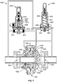
Referring to FIG. 6, an example of a control system 500 is shown having an adjustable deadband for back pressure regulators or relief valves that allows for opening of the pressure regulator at one pressure and closing at a different pressure. Control system 500 can also prevent fluid pressure from traveling back through the pressure regulator, essentially doubling as a check valve. Control system 500 generally includes a pressure regulator 520, a first pilot 540, and a second pilot 560.
Pressure regulator 520 is a standard back-pressure regulator or relief valve, such as a Tartarini® Type FL Backpressure Regulator. In the example shown in FIG. 6, pressure regulator 520 has a body 522 and an actuator assembly 530. Body 522 defines fluid inlet 524, fluid outlet 526, and valve seat 525 between fluid inlet 524 and fluid outlet 526. Valve plug 528 is movable within body 522 between an open position, where valve plug 528 is spaced from valve seat 525 and a process fluid is allowed to flow through pressure regulator 520 from fluid inlet 524 to fluid outlet 526, and a closed position, where valve plug 528 sealing engages valve seat 525 and the process fluid is prevented from flowing through pressure regulator 520. Actuator assembly 530 defines cavity 534 and diaphragm assembly 536 is disposed within cavity 534 to divide cavity 534 into first chamber 538, which is in fluid communication with fluid outlet 526, and second chamber 539, which is in fluid communication with second port 574 of first pilot and first port 553 of second pilot 560. Diaphragm assembly 536 is operatively connected to valve plug 528 such that valve plug 528 moves with diaphragm assembly 536 to move valve plug 528 into and out of sealing engagement with valve seat 525. Biasing member 532, such as a compression spring, is disposed in first chamber 538 to bias valve plug 528 of pressure regulator 520 towards the closed position.
First pilot 540 is a standard spring to close pilot, such as a Tartarini® PRX/182. In the example shown in FIG. 6, first pilot 540 includes housing 562, which defines cavity 564. First and second diaphragm assemblies 566, 568 are disposed in cavity 564 to divide cavity 564 into first chamber 570, second chamber 572, and third chamber 576. Biasing member 571, such as a compression spring, is positioned in first chamber 570 to bias first pilot 540 into a closed position. First port 573 is formed in housing 562 and is in fluid communication with fluid inlet 524 of fluid regulator 520. Second port 574 is formed in housing 562 and is in fluid communication with second chamber 539 and with first port 553 of second pilot 560. Third port 577 is formed in housing 562 and is in fluid communication with fluid inlet 524 of pressure regulator 520 and with second diaphragm assembly 568. First diaphragm assembly 566 also includes a plug that moves with first diaphragm assembly 566 and second diaphragm assembly 568 in response to fluid pressure at the third port 577 between an open position, in which the plug is spaced apart from a seat and fluid is allowed to flow between first port 573 and second port 574, and a closed position, in which the plug sealingly engages the seat and fluid is prevented from flowing between first port 573 and second port 574.
Second pilot 560 is a standard spring to open pilot, such as a Tartarini® PRX/120. In the example shown in FIG. 6, second pilot 560 includes housing 542, which defines cavity 544. First and second diaphragm assemblies 546, 548 are disposed in cavity 544 to divide cavity 544 into first chamber 550, second chamber 552, and third chamber 556. Biasing member 551, such as a compression spring, is positioned in first chamber 550 to bias second pilot 560 into an open position. First port 553 is formed in housing 542 and is in fluid communication with second port 574 of first pilot 540 and with second chamber 539 of actuator assembly 530 of pressure regulator 520. Second port 554 is formed in housing 542 and is in fluid communication with fluid outlet 526 of fluid regulator 520. Third port 557 is formed in housing 542 and is in fluid communication with fluid inlet 524 of pressure regulator 520 and with second diaphragm assembly 548. Second diaphragm assembly 548 also includes a plug that moves with first diaphragm assembly 546 and second diaphragm assembly 548 in response to fluid pressure at third port 557 between an open position, in which the plug is spaced apart from a seat and fluid is allowed to flow between first port 553 and second port 554, and a closed position, in which the plug sealing engages the seat and fluid is prevented from flowing between first port 553 and second port 554.
In operation, first pilot 540 could be set to a first setpoint (e.g., 13 bar), which could be the pressure at which pressure regulator 520 would move from the normally closed to an open position. In addition, second pilot 560 could be set to a second setpoint (e.g., 11 bar), lower than the first setpoint, which could be the pressure at which pressure regulator 520 would reset and move from the open to the closed position. In this example, the dead band for control system 500 is set by setting the setpoint for first pilot 540 above the setpoint for second pilot 560.
During a first mode of operation, the pressure of the process fluid at fluid inlet 524 of pressure regulator 520 would be below both the first and second setpoints. When the fluid pressure at fluid inlet 524 is below both the first and second setpoints, first pilot 540 is in the closed position and second pilot 560 is in the open position. Therefore, the pressure in first chamber 538 and second chamber 539 of pressure regulator 520 are both equal to the fluid pressure at the fluid outlet 526, the forces from the fluid pressures acting on diaphragm assembly are equalized, biasing element 532 urges valve plug 528 into engagement with valve seat 525, and pressure regulator 520 remains in the closed position. In this first mode of operation, second chamber 539 of pressure regulator 520 is fluidly coupled to fluid outlet 526 through second pilot 560, which is open, and is isolated from fluid inlet 524 by first pilot 540, which is closed.
During a second mode of operation, the pressure of the process fluid at fluid inlet 524 increases and becomes greater than the second setpoint (but still less than the first setpoint) and second pilot 560 moves from the open position to the closed position, trapping the outlet pressure in second chamber 539 of pressure regulator 520, and first pilot 540 remains in the closed position. In the closed position, fluid pressure at third port 557 of second pilot 560 will move the plug into sealing engagement with the seat and prevent the flow of pressurized fluid from fluid outlet 526 into second chamber 539 of pressure regulator 20. In this second mode of operation, second chamber 539 of pressure regulator 520 is isolated from fluid outlet 526 by second pilot 560, which is closed, and is isolated from fluid inlet 524 by first pilot 540. Because the trapped pressure in second chamber 539 is equal to the pressure at the fluid outlet 526, pressure regulator 520 will remain in the closed position.
During a third mode of operation, the pressure of the process fluid at fluid inlet 524 continues to increase and becomes greater than the first setpoint (and still greater than the second setpoint) and first pilot 540 will move from a closed to an open position, fluidly connecting second chamber 539 of pressure regulator 520 to fluid inlet 524, and second pilot 560 remains in the closed position. In the open position, fluid pressure at third port 577 of first pilot 540 will move the plug away from the seat and allow the flow of fluid between first port 573, which is in fluid communication with fluid inlet 524, and second port 574, which is in fluid communication with second chamber 539 of pressure regulator 520. The increase in pressure in second chamber 539 will create an imbalance in the forces acting on diaphragm assembly 536, which moves valve plug 528 away from valve seat 525, placing pressure regulator 520 in the open position and allowing the flow of the process fluid through pressure regulator 520. In this third mode of operation, second chamber 539 of pressure regulator 520 is fluidly coupled to fluid inlet 524 through first pilot 540, which is open, and is isolated from fluid outlet 526 by second pilot 560, which is closed. Because first chamber 538 is open to fluid outlet 526 and second chamber 539 is open to fluid inlet 524 and the fluid pressures at fluid inlet 524 and fluid outlet 526 will fluctuate when pressure regulator 520 is in the open position in the third mode of operation, pressure regulator 520 can modulate in response to the fluid pressure at fluid outlet 526 with the fluid pressure at fluid inlet 524 greater than the first setpoint.
With pressure regulator 520 in the open position, the pressure at fluid inlet 524 will decrease. As the pressure of the process fluid at fluid inlet 524 decreases and drops below the first setpoint of first pilot 540 (but still above the second setpoint of second pilot 560), first pilot 540 will move from the open to the closed position, which prevents the flow of fluid from fluid inlet 524 to second chamber 539 of pressure regulator 520. At this point, the inlet pressure is trapped in second chamber 539 of pressure regulator 520, which remains in the open position.
As the pressure of the process fluid at fluid inlet 524 continues to decrease and drops below the second setpoint of second pilot 560, second pilot 560 will move from the closed to the open position, which will vent the inlet pressure from second chamber 539 of pressure regulator 520 to fluid outlet 526 and the pressure in second chamber 539 will again stabilize at the outlet pressure of fluid outlet 526. As the pressure in second chamber 539 decreases, diaphragm assembly 536 will move valve plug 528 toward valve seat 525 and to the closed position and automatically reset pressure regulator 520. As the fluid pressure forces acting on both sides of diaphragm assembly 536 rebalance, biasing element 532 will urge pressure regulator 520 into the closed position.
FIG. 7 illustrates a control system 600, which is an alternate embodiment of the control system 500 of FIG. 6, using different types of pilots. Control system 600 also generally includes a pressure regulator 520, a first pilot 640 and a second pilot 660.
Pressure regulator 520 is a standard back-pressure regulator or relief valve, such as a Tartarini® Type FL Backpressure Regulator, as described above.
First pilot 640 is a spring to close pilot, such as a Fisher® Type 6358 Series Pilot. In the example shown in FIG. 7, first pilot 640 includes housing 662, which defines cavity 664. Diaphragm assembly 668 is disposed in cavity 664 to divide cavity 664 into first chamber 670 and second chamber 672. Biasing member 671, such as a compression spring, is positioned in first chamber 670 to bias first pilot 640 into a closed position. First port 673 is formed in housing 662 and is in fluid communication with fluid inlet 524 of fluid regulator 520 and with second chamber 672 and diaphragm assembly 668. Second port 674 is formed in housing 662 and is in fluid communication with second chamber 539 and with first port 653 of second pilot 660. Diaphragm assembly 668 also includes a plug that moves with diaphragm assembly 668 in response to fluid pressure in second chamber 672 from first port 673 and is movable between an open position, in which the plug is spaced apart from a seat and fluid is allowed to flow between first port 673 and second port 674, and a closed position, in which the plug sealingly engages the seat and fluid is prevented from flowing between first port 673 and second port 674.
Second pilot 660 is a spring to open pilot, such as a Fisher® Type 161 Series Pilot. In the example shown in FIG. 7, second pilot 660 includes housing 642, which defines cavity 644. Diaphragm assembly 646 is disposed in cavity 644 to divide cavity 644 into first chamber 650 and second chamber 652. Biasing member 651, such as a compression spring, is positioned in first chamber 650 to bias second pilot 660 into an open position. First port 653 is formed in housing 642 and is in fluid communication with second port 674 of first pilot 640 and with second chamber 539 of pressure regulator 520. Second port 654 is formed in housing 642 and is in fluid communication with fluid outlet 526 of fluid regulator 520. Third port 657 is formed in housing 642 and is in fluid communication with fluid inlet 524 of pressure regulator 520 and with diaphragm assembly 646. Diaphragm assembly 646 also includes a plug that moves with second diaphragm assembly 646 in response to fluid pressure at third port 657 and is movable between an open position, in which the plug is spaced apart from a seat and fluid is allowed to flow between first port 653 and second port 654, and a closed position, in which the plug sealing engages the seat and fluid is prevented from flowing between first port 653 and second port 654.
In operation, first pilot 640 could be set to a first setpoint (e.g., 13 bar), which could be the pressure at which pressure regulator 520 would move from the normally closed to an open position. In addition, second pilot 660 could be set to a second setpoint (e.g., 11 bar), lower than the first setpoint, which could be the pressure at which pressure regulator 520 would reset and move from the open to the closed position. In this example, the dead band for control system 600 is set by setting the setpoint for first pilot 640 above the setpoint for second pilot 660.
During a first mode of operation, the pressure of the process fluid at fluid inlet 524 of pressure regulator 520 would be below both the first and second setpoints. When the fluid pressure at fluid inlet 524 is below both the first and second setpoints, first pilot 640 is in the closed position and second pilot 660 is in the open position. Therefore, the pressure in first chamber 538 and second chamber 539 of pressure regulator 520 are both equal to the fluid pressure at the fluid outlet 526, the forces from the fluid pressures acting on diaphragm assembly are equalized, biasing element 532 urges valve plug 528 into engagement with valve seat 525, and pressure regulator 520 remains in the closed position. In this first mode of operation, second chamber 539 of pressure regulator 520 is fluidly coupled to fluid outlet 526 through second pilot 660, which is open, and is isolated from fluid inlet 524 by first pilot 640, which is closed.
During a second mode of operation, the pressure of the process fluid at fluid inlet 524 increases and becomes greater than the second setpoint (but still less than the first setpoint) and second pilot 660 moves from the open position to the closed position, trapping the outlet pressure in second chamber 539 of pressure regulator 520. In the closed position, fluid pressure at third port 657 of second pilot 660 will move the plug into sealing engagement with the seat and prevent the flow of pressurized fluid from fluid outlet 526 into second chamber 539 of pressure regulator 20. In this second mode of operation, second chamber 539 of pressure regulator 520 is isolated from fluid outlet 526 by second pilot 660, which is closed, and is isolated from fluid inlet 524 by first pilot 640. Because the trapped pressure in second chamber 539 is equal to the pressure at fluid outlet 526, pressure regulator 520 will remain in the closed position.
During a third mode of operation, the pressure of the process fluid at fluid inlet 524 continues to increase and becomes greater than the first setpoint and first pilot 640 will move from a closed to an open position, fluidly connecting second chamber 539 of pressure regulator 520 to fluid inlet 524. In the open position, fluid pressure in second chamber 672 from first port 673 of first pilot 640 will move the plug away from the seat and allow the flow of fluid between first port 673, which is in fluid communication with fluid inlet 524, and second port 674, which is in fluid communication with second chamber 539 of pressure regulator 520. The increase in pressure in second chamber 539 will create an imbalance in the forces acting on diaphragm assembly 536, which moves valve plug 528 away from valve seat 525, placing pressure regulator 520 in the open position and allowing the flow of the process fluid through pressure regulator 520. In this third mode of operation, second chamber 539 of pressure regulator 520 is fluidly coupled to fluid inlet 524 through first pilot 640, which is open, and is isolated from fluid outlet 526 by second pilot 660, which is closed.
With pressure regulator 520 in the open position, the pressure at fluid inlet 524 will decrease. As the pressure of the process fluid at fluid inlet 524 decreases and drops below the first setpoint of first pilot 640 (but still above the second setpoint of second pilot 660), first pilot 640 will move from the open to the closed position, which prevents the flow of fluid from fluid inlet 524 to second chamber 539 of pressure regulator 520. At this point, the inlet pressure is trapped in second chamber 539 of pressure regulator 520, which remains in the open position.
As the pressure of the process fluid at fluid inlet 524 continues to decrease and drops below the second setpoint of second pilot 660, second pilot 660 will move from the closed to the open position, which will vent the inlet pressure from second chamber 539 of pressure regulator 520 to fluid outlet 526 and the pressure in second chamber 539 will again stabilize at the outlet pressure of fluid outlet 526. As the pressure in second chamber 539 decreases, diaphragm assembly 536 will move valve plug 528 toward valve seat 525 and to the closed position and automatically reset pressure regulator 520. As the fluid pressure forces acting on both sides of diaphragm assembly 536 rebalance, biasing element 532 will urge pressure regulator 520 into the closed position.
FIG. 8 illustrates a control system 700 that includes pressure regulator 520, first pilot 540, and second pilot 560, as described for control system 500 above. In control system 700, pressure regulator 520, first pilot 540, and second pilot 560 are arranged the same and operate the same as discussed above for control system 500. In addition, control system 700 also includes a downstream fluid control device. In the illustrated embodiment, the downstream fluid control device is second pressure regulator 720, which is configured to control a fluid pressure downstream of second pressure regulator 720. In other embodiments, the downstream fluid control device may be a control valve, a relief valve, a back-pressure regulator, or any other fluid control device.
Second pressure regulator 720 is a pressure-reducing regulator, such as a Tartarini® Type FL Regulator. In the example shown in FIG. 8, second pressure regulator 720 has a body 722 and an actuator assembly 730. Body 722 defines fluid inlet 724 in fluid communication with fluid outlet 526 of pressure regulator 520, fluid outlet 726, and valve seat 725 between fluid inlet 724 and fluid outlet 726. Valve plug 728 is movable within body 722 between an open position, where valve plug 728 is spaced from valve seat 725 and a process fluid is allowed to flow through second pressure regulator 720 from fluid inlet 724 to fluid outlet 726, and a closed position, where valve plug 728 sealing engages valve seat 725 and the process fluid is prevented from flowing through second pressure regulator 720. Actuator assembly 730 defines cavity 734 and diaphragm assembly 736 is disposed within cavity 734 to divide cavity 734 into first chamber 738, which is in fluid communication with fluid outlet 726, and second chamber 739, which is in fluid communication with third pilot 740. Diaphragm assembly 736 is operatively connected to valve plug 728 such that valve plug 728 moves with diaphragm assembly 736 to move valve plug 728 into and out of sealing engagement with valve seat 725. Biasing member 732, such as a compression spring, is disposed in first chamber 738 to bias valve plug 728 of pressure regulator 720 toward the closed position.
Third pilot 740 is a standard spring to open pilot, such as a Fisher® Type PRX Pilot that is configured to supply a loading pressure, such as the fluid pressure from fluid inlet 724 and/or from an output of pressure stabilizer 760, to second chamber 739 of second pressure regulator 720 in response to the fluid pressure at fluid outlet 726 of second pressure regulator 720.
Pressure stabilizer 760 is a standard pressure stabilizer, such as a Tartarini® Type SA/2 Pressure Stabilizer. Pressure stabilizer 760 receives a fluid pressure from fluid inlet 724 of second pressure regulator 720 and regulates the flow of fluid from fluid inlet 726 to third pilot 740 based on the fluid pressure at fluid outlet 726.
With first pilot 540 having a setpoint of 13 bar and second pilot 560 having a setpoint of 11 bar, as discussed in detail above, control system 700 will operate as follows:
Intermediate
Inlet Pressure Loading Outlet
Pressure at at Fluid Pressure at Pressure at Position of
Fluid Inlet Outlet 526 and Second Fluid Outlet Pressure
524 Fluid Inlet 724 Chamber 539 726 Regulator
(bar) (bar) (bar) (bar) 520
10 4 4 4 Close
11 4 4 4 Close
12 4 4 4 Close
13 13 13 4 Open/Close*
14 14 14 4 Open/Close*
13 13 13 4 Open/Close*
12 12 13 4 Open
11 4 4 4 Close
10 4 4 4 Close
*The unit will open based on demand. As the intermediate pressure decreases due to demand increase the unit opens.
FIG. 9 illustrates a control system 800 that is identical to control system 700, except that first chamber 528 of pressure regulator 520 and second port 554 of second pilot 560 are in fluid communication with fluid outlet 726 of the downstream fluid control device (again the second pressure regulator 720 in the illustrated embodiment), rather than with fluid outlet 526 of pressure regulator 520.
With first pilot 540 having a setpoint of 13 bar and second pilot 560 having a setpoint of 11 bar, as discussed in detail above, control system 800 will operate as follows:
Inlet Intermediate Loading Outlet
Pressure at Pressure at Fluid Pressure at Pressure at Position of
Fluid Inlet Outlet 526 and Second Fluid Outlet Pressure
524 Fluid Inlet 724 Chamber 539 726 Regulator
(bar) (bar) (bar) (bar) 520
10 4 4 4 Close
11 4 4 4 Close
12 4 4 4 Close
13 13 13 4 Open
14 14 14 4 Open
13 13 13 4 Open
12 12 13 4 Open
11 4 4 4 Close
10 4 4 4 Close
The difference between control system 700 and control system 800 is how pressure regulator 520 behaves when first pilot 540 is open. In control system 700, pressure regulator 520 will open when pressure decreases due to demand when first pilot 540 is open. In control system 800, pressure regulator 520 will always be open when first pilot 540 is open.
Control system 700 can be used for safety purposes. In the event one of the seats of first pilot 540 or second pilot 560 do not lock up, pressure will leak by. If the first and second pilots 540, 560 are registering and bleeding to downstream pressure, then the pressure will bleed downstream, which can bypass all over pressure protection methods.
While various embodiments have been described above, this disclosure is not intended to be limited thereto. Variations can be made to the disclosed embodiments that are still within the scope of the appended claims.

Claims (14)

What is claimed is:
1. A control system, comprising:
a pressure regulator comprising a fluid inlet, a fluid outlet, and an actuator assembly, the actuator assembly comprising a cavity and a diaphragm assembly disposed within the cavity and dividing the cavity into a first chamber and a second chamber, the first chamber in fluid communication with the fluid outlet;
a first pilot in direct fluid communication with the second chamber of the actuator assembly and the fluid inlet, the first pilot having a first setpoint; and
a second pilot in direct fluid communication with the second chamber of the actuator assembly, the fluid inlet, and the fluid outlet, the second pilot having a second setpoint that is less than the first setpoint; wherein
the first pilot and the second pilot are configured to:
fluidly couple the second chamber to the fluid outlet and isolate the second chamber from the fluid inlet with the control system in a first mode of operation;
isolate the second chamber from the fluid outlet and the fluid inlet with the control system in a second mode of operation; and
fluidly couple the second chamber to the fluid inlet with the control system in a third mode of operation.
2. The control system of claim 1, wherein:
the first pilot is configured to be in a closed position and the second pilot is configured to be in an open position with the control system in the first mode of operation;
the first pilot is configured to be in the closed position and the second pilot is configured to be in a closed position with the control system in the second mode of operation; and
the first pilot is configured to be in an open position and the second pilot is configured to be in the closed position with the control system in the third mode of operation.
3. The control system of claim 1, wherein:
the control system is configured to operate in the first mode of operation with a fluid pressure at the fluid inlet below the first setpoint and below the second setpoint;
the control system is configured to operate in the second mode of operation with the fluid pressure at the fluid inlet above the second setpoint and below the first setpoint; and
the control system is configured to operate in the third mode of operation with the fluid pressure at the fluid inlet above the first setpoint and above the second setpoint.
4. The control system of claim 1, wherein the pressure regulator is configured to be closed when a fluid pressure at the fluid inlet transitions from a value below the second setpoint to a value between the first setpoint and the second setpoint and configured to be open when the fluid pressure at the fluid inlet transitions from a value above the first setpoint to a value between the first setpoint and the second setpoint.
5. The control system of claim 4, where the pressure regulator is configured to modulate in response to a fluid pressure at the fluid outlet with the fluid pressure at the fluid inlet greater than the first setpoint.
6. The control system of claim 1, wherein:
the pressure regulator is configured to be in a closed position with a fluid pressure at the fluid inlet below the second setpoint; and
the pressure regulator is configured to be in an open position with the fluid pressure at the fluid inlet above the first setpoint.
7. The control system of claim 1, wherein the pressure regulator is a back-pressure regulator.
8. The control system of claim 7, wherein the pressure regulator comprises a spring disposed in the first chamber to urge the pressure regulator towards the closed position.
9. The control system of claim 1, further comprising a downstream fluid control device in fluid communication with the fluid outlet of the pressure regulator.
10. The control system of claim 9, wherein the downstream fluid control device is a second pressure regulator that is configured to control a fluid pressure downstream of the second pressure regulator.
11. A control system, comprising:
a pressure regulator comprising a fluid inlet, a fluid outlet, and an actuator assembly, the actuator assembly comprising a cavity and a diaphragm assembly disposed within the cavity and dividing the cavity into a first chamber and a second chamber, the first chamber in fluid communication with the fluid outlet;
a first pilot in fluid communication with the second chamber of the actuator assembly and the fluid inlet, the first pilot having a first setpoint and; and
a second pilot in fluid communication with the second chamber of the actuator assembly, the fluid inlet, and the fluid outlet, the second pilot having a second setpoint that is less than the first setpoint; wherein
the first pilot comprises a first port in fluid communication with the fluid inlet of the pressure regulator, a second port in fluid communication with the second pilot and the second chamber of the pressure regulator, and a third port in fluid communication with the fluid inlet of the pressure regulator and with a diaphragm assembly of the first pilot; and
the first pilot and the second pilot are configured to:
fluidly couple the second chamber to the fluid outlet and isolate the second chamber from the fluid inlet with the control system in a first mode of operation;
isolate the second chamber from the fluid outlet and the fluid inlet with the control system in a second mode of operation; and
fluidly couple the second chamber to the fluid inlet with the control system in a third mode of operation.
12. The control system of claim 11, wherein the first pilot comprises a spring to urge the first pilot toward the closed position.
13. The control system of claim 11, wherein the second pilot comprises a first port in fluid communication with the second port of the first pilot and the second chamber of the pressure regulator, a second port in fluid communication with the fluid outlet of the pressure regulator, and a third port in fluid communication with the fluid inlet of the pressure regulator and with a diaphragm assembly of the second pilot.
14. The control system of claim 13, wherein the second pilot comprises a spring to urge the second pilot toward the open position.
US16/180,241 2015-06-03 2018-11-05 Adjustable deadband control system Active 2035-12-11 US11137781B2 (en)

Priority Applications (3)

Application Number Priority Date Filing Date Title
US16/180,241 US11137781B2 (en) 2015-06-03 2018-11-05 Adjustable deadband control system
PCT/US2019/059055 WO2020096850A1 (en) 2015-06-03 2019-10-31 Adjustable deadband control system
US17/481,828 US11733722B2 (en) 2015-06-03 2021-09-22 Adjustable deadband control system

Applications Claiming Priority (4)

Application Number Priority Date Filing Date Title
US201562170453P 2015-06-03 2015-06-03
US14/825,454 US9760097B2 (en) 2015-06-03 2015-08-13 Adjustable deadband control system
US15/673,053 US10678274B2 (en) 2015-06-03 2017-08-09 Adjustable deadband control system
US16/180,241 US11137781B2 (en) 2015-06-03 2018-11-05 Adjustable deadband control system

Related Parent Applications (2)

Application Number Title Priority Date Filing Date
US15/673,053 Continuation US10678274B2 (en) 2015-06-03 2017-08-09 Adjustable deadband control system
US15/673,053 Continuation-In-Part US10678274B2 (en) 2015-06-03 2017-08-09 Adjustable deadband control system

Related Child Applications (1)

Application Number Title Priority Date Filing Date
US17/481,828 Division US11733722B2 (en) 2015-06-03 2021-09-22 Adjustable deadband control system

Publications (2)

Publication Number Publication Date
US20190072194A1 US20190072194A1 (en) 2019-03-07
US11137781B2 true US11137781B2 (en) 2021-10-05

Family

ID=56203939

Family Applications (4)

Application Number Title Priority Date Filing Date
US14/825,454 Active 2035-12-18 US9760097B2 (en) 2015-06-03 2015-08-13 Adjustable deadband control system
US15/673,053 Active 2036-01-25 US10678274B2 (en) 2015-06-03 2017-08-09 Adjustable deadband control system
US16/180,241 Active 2035-12-11 US11137781B2 (en) 2015-06-03 2018-11-05 Adjustable deadband control system
US17/481,828 Active 2035-09-24 US11733722B2 (en) 2015-06-03 2021-09-22 Adjustable deadband control system

Family Applications Before (2)

Application Number Title Priority Date Filing Date
US14/825,454 Active 2035-12-18 US9760097B2 (en) 2015-06-03 2015-08-13 Adjustable deadband control system
US15/673,053 Active 2036-01-25 US10678274B2 (en) 2015-06-03 2017-08-09 Adjustable deadband control system

Family Applications After (1)

Application Number Title Priority Date Filing Date
US17/481,828 Active 2035-09-24 US11733722B2 (en) 2015-06-03 2021-09-22 Adjustable deadband control system

Country Status (5)

Country Link
US (4) US9760097B2 (en)
EP (1) EP3304238B1 (en)
CN (2) CN106249769B (en)
MX (1) MX2017015446A (en)
WO (2) WO2016196871A1 (en)

Cited By (1)

* Cited by examiner, † Cited by third party
Publication number Priority date Publication date Assignee Title
US20220146052A1 (en) * 2020-11-06 2022-05-12 Vrg Controls Llc Monitor control valve with backflow prevention

Families Citing this family (16)

* Cited by examiner, † Cited by third party
Publication number Priority date Publication date Assignee Title
EP2972139A4 (en) 2013-03-15 2016-10-12 Mueller Int Llc Systems for measuring properties of water in a water distribution system
US9760097B2 (en) 2015-06-03 2017-09-12 Emerson Process Management Regulator Technologies, Inc. Adjustable deadband control system
US11041839B2 (en) 2015-06-05 2021-06-22 Mueller International, Llc Distribution system monitoring
CN106802676B (en) * 2017-03-08 2019-12-17 成都九门科技有限公司 driving voltage regulator
CN107246498B (en) * 2017-07-26 2023-10-20 中国长江电力股份有限公司 Double pilot valve control system and control method for pressure reducing valve of water supply system
CN108223867A (en) * 2017-12-27 2018-06-29 杭州春江阀门有限公司 A kind of Depressure valve
RU2687198C1 (en) * 2018-08-03 2019-05-07 Федеральное государственное автономное образовательное учреждение высшего образования "Сибирский федеральный университет" Control method of valves of pulse-safety device and device for its implementation
RO134311A2 (en) * 2018-10-10 2020-07-30 Emerson Process Management Regulator Technologies Inc. Slam shut-off safety assembly for providing redundant safety switch-off
US11713827B2 (en) * 2019-04-30 2023-08-01 Dresser, Llc Expandable pilot assembly for pressure regulators
US11713828B2 (en) * 2019-04-30 2023-08-01 Dresser, Llc Pilot-operated pressure regulator
MX2022000748A (en) * 2019-07-19 2022-04-26 Emerson Automation Solutions Final Control US LP Rapid dome loading pilot valve bypass.
US11306838B2 (en) * 2020-03-27 2022-04-19 Dresser, Llc Pilot-operated pressure relief valve nozzle
US11953098B2 (en) * 2020-06-30 2024-04-09 Ademco Inc. Inlet controlled regulating valve
US11725366B2 (en) 2020-07-16 2023-08-15 Mueller International, Llc Remote-operated flushing system
CN111963738A (en) * 2020-10-20 2020-11-20 四川九门科技股份有限公司 Remote pressure monitoring device
US20220187857A1 (en) * 2020-12-10 2022-06-16 Griswold Industries Control system for regulating waterworks pressure

Citations (35)

* Cited by examiner, † Cited by third party
Publication number Priority date Publication date Assignee Title
US285163A (en) * 1883-09-18 Fluid peessuee eectlatoe
US843174A (en) * 1906-09-24 1907-02-05 Miron G Reynolds Pressure-controlling system.
US871260A (en) * 1907-07-15 1907-11-19 Dyer Company Pressure regulator and reducer.
US985175A (en) * 1909-10-19 1911-02-28 Jesse B Hirst Gas-pressure reducing and regulating mechanism.
US1110320A (en) 1913-06-23 1914-09-15 Chaplin Fulton Mfg Company Gas relief-valve.
US1189349A (en) 1909-02-06 1916-07-04 Frank L Cross Pressure-regulator for gas systems.
US1767702A (en) * 1928-05-10 1930-06-24 Swiss Locomotive & Machine Works Regulating valve
US1995949A (en) * 1929-05-29 1935-03-26 Spence Paulsen Regulating valve
US2543846A (en) 1944-02-29 1951-03-06 Clayton Manufacturing Co Quick-operating pressure relief valve
US2690760A (en) * 1952-08-06 1954-10-05 Reynolds Gas Regulator Company Fluid pressure regulating system
US2707970A (en) * 1952-11-24 1955-05-10 Reynolds Gas Regulator Company Fluid pressure distributing system
US2731032A (en) * 1952-08-07 1956-01-17 Reynolds Gas Regulator Company Fluid pressure regulating system
US3977423A (en) 1975-03-14 1976-08-31 Phillips Petroleum Company Valve control apparatus and method
US4090526A (en) 1975-04-07 1978-05-23 Mojonnier Bros. Co. Gas pressure stabilizer system and valve
US4250913A (en) 1979-05-07 1981-02-17 Leslie Co. Pilot mechanism for pressure regulating valve
US4961441A (en) * 1989-11-13 1990-10-09 Salter Stuart C Method and system for controlling a pressure regulator
US5348036A (en) 1993-05-04 1994-09-20 Singer Valve Inc. Automatic control valve
US5660198A (en) * 1995-12-21 1997-08-26 J. C. Carter Company, Inc. Flow compensated pressure control system
US6035878A (en) * 1997-09-22 2000-03-14 Fisher Controls International, Inc. Diagnostic device and method for pressure regulator
US20020036013A1 (en) * 2000-09-22 2002-03-28 Naoto Inayama Fluid pressure controller
US20040261857A1 (en) * 2003-04-29 2004-12-30 David Webster Pipeline protection system
US6935362B1 (en) * 1999-06-04 2005-08-30 Technolog Limited Pilot valve
US20050265823A1 (en) * 2004-05-27 2005-12-01 Wiggins Jimmy D Pneumatic valve control having improved opening characteristics and an air turbine starter incorporating the same
US20080023662A1 (en) 2005-07-07 2008-01-31 Reinicke Robert H Multi-functional regulator
US20080251130A1 (en) 2007-04-13 2008-10-16 Cla-Val Co. System and method for hydraulically managing fluid pressure downstream from a main valve
US20080251146A1 (en) 2007-04-13 2008-10-16 Cla-Val Co. System and method for hydraulically managing fluid pressure downstream from a main valve between set points
US20100071787A1 (en) 2007-10-29 2010-03-25 Cla-Val Co. System, including a variable orifice assembly, for hydraulically managing pressure in a fluid distribution system between pressure set points
US7814750B2 (en) * 2004-11-15 2010-10-19 Knorr-Bremse Systeme Fuer Nutzfahzeuge Gmbh Device for supplying pressure to a piston actuator
US20100301238A1 (en) * 2009-05-26 2010-12-02 Honeywell International Inc. Bi-directional overpressure shut-off valve
US20130092259A1 (en) 2011-10-17 2013-04-18 James Lyman Griffin, JR. Pilot operated fluid regulators having a reset apparatus and related methods
US20140182694A1 (en) 2012-12-28 2014-07-03 Emerson Process Management Regulator Technologies, Inc. Backpressure regulator for easy pump start-up
US20150114492A1 (en) 2013-10-31 2015-04-30 Singer Valve, Inc. Automatic flow control system and apparatus
US9086702B2 (en) 2011-07-01 2015-07-21 Emerson Process Management Regulator Technologies, Inc. Pressure-balanced fluid pressure regulators
US20160356389A1 (en) 2015-06-03 2016-12-08 Emerson Process Management Regulator Technologies, Inc. Adjustable deadband control system
US20180314273A1 (en) * 2017-04-27 2018-11-01 Marotta Controls, Inc. Electronically controlled regulator

Family Cites Families (21)

* Cited by examiner, † Cited by third party
Publication number Priority date Publication date Assignee Title
US1014830A (en) * 1910-01-31 1912-01-16 Ernest F Lloyd Pressure-increaser.
US2309848A (en) * 1937-06-05 1943-02-02 William R King Differential pressure loaded control valve
US2257171A (en) * 1938-01-13 1941-09-30 William R King Low pressure booster regulator
US5047965A (en) * 1989-01-05 1991-09-10 Zlokovitz Robert J Microprocessor controlled gas pressure regulator
US5097858A (en) * 1990-05-01 1992-03-24 Zlokovitz Robert J Clock controlled gas pressure regulator
IT1315469B1 (en) * 2000-07-17 2003-02-18 Pietro Fiorentini Spa PRESSURE REGULATOR FOR DIGAS TRANSPORT AND DISTRIBUTION SYSTEMS.
US7523762B2 (en) * 2006-03-22 2009-04-28 Honeywell International Inc. Modulating gas valves and systems
EP2446168B1 (en) * 2009-06-25 2014-03-05 Öhlins Racing Ab Pressure regulator comprising an actuator
US8245727B2 (en) * 2009-06-26 2012-08-21 Pamela Mooney, legal representative Flow control valve and method of use
EP2721206B1 (en) * 2011-06-15 2016-08-03 Picanol Air supply system for an airjet weaving machine
DE102012216242A1 (en) * 2012-09-13 2014-03-13 Putzmeister Engineering Gmbh Device for drive control of a two-cylinder slurry pump
US9297465B2 (en) * 2012-10-01 2016-03-29 Emerson Process Management Regulator Technologies, Inc. Pilot-operated regulator with balanced port
ITVI20130136A1 (en) * 2013-05-17 2014-11-18 Pietro Fiorentini Spa PRESSURE REGULATOR FOR A GAS AND PILOT METHOD FOR THIS PRESSURE REGULATOR
US20140358303A1 (en) * 2013-06-03 2014-12-04 Tescom Corporation Method and Apparatus for Stabilizing Pressure in an Intelligent Regulator Assembly
US10203706B2 (en) * 2013-06-03 2019-02-12 Tescom Corporation Method and apparatus for conditional control of an electronic pressure regulator
CN103336512B (en) * 2013-06-29 2015-12-02 上海飞奥燃气设备有限公司 Gas transmission and distribution intelligent management apapratus
US9298189B2 (en) * 2013-10-31 2016-03-29 Singer Valve Inc. Automatic flow control system and apparatus
EP2886834A1 (en) * 2013-12-20 2015-06-24 IMI Hydronic Engineering International SA A valve and a method of controlling a valve in a fluid conduit
CN204241173U (en) * 2014-09-16 2015-04-01 光宝电子(广州)有限公司 The airtight leak-checking apparatus of pressure-decreasing type
CN104482279B (en) * 2014-12-12 2016-10-05 乐山川天燃气输配设备有限公司 Under-voltage auto-closing pressure regulator after valve
CN106802676B (en) * 2017-03-08 2019-12-17 成都九门科技有限公司 driving voltage regulator

Patent Citations (36)

* Cited by examiner, † Cited by third party
Publication number Priority date Publication date Assignee Title
US285163A (en) * 1883-09-18 Fluid peessuee eectlatoe
US843174A (en) * 1906-09-24 1907-02-05 Miron G Reynolds Pressure-controlling system.
US871260A (en) * 1907-07-15 1907-11-19 Dyer Company Pressure regulator and reducer.
US1189349A (en) 1909-02-06 1916-07-04 Frank L Cross Pressure-regulator for gas systems.
US985175A (en) * 1909-10-19 1911-02-28 Jesse B Hirst Gas-pressure reducing and regulating mechanism.
US1110320A (en) 1913-06-23 1914-09-15 Chaplin Fulton Mfg Company Gas relief-valve.
US1767702A (en) * 1928-05-10 1930-06-24 Swiss Locomotive & Machine Works Regulating valve
US1995949A (en) * 1929-05-29 1935-03-26 Spence Paulsen Regulating valve
US2543846A (en) 1944-02-29 1951-03-06 Clayton Manufacturing Co Quick-operating pressure relief valve
US2690760A (en) * 1952-08-06 1954-10-05 Reynolds Gas Regulator Company Fluid pressure regulating system
US2731032A (en) * 1952-08-07 1956-01-17 Reynolds Gas Regulator Company Fluid pressure regulating system
US2707970A (en) * 1952-11-24 1955-05-10 Reynolds Gas Regulator Company Fluid pressure distributing system
US3977423A (en) 1975-03-14 1976-08-31 Phillips Petroleum Company Valve control apparatus and method
US4090526A (en) 1975-04-07 1978-05-23 Mojonnier Bros. Co. Gas pressure stabilizer system and valve
US4250913A (en) 1979-05-07 1981-02-17 Leslie Co. Pilot mechanism for pressure regulating valve
US4961441A (en) * 1989-11-13 1990-10-09 Salter Stuart C Method and system for controlling a pressure regulator
US5348036A (en) 1993-05-04 1994-09-20 Singer Valve Inc. Automatic control valve
US5660198A (en) * 1995-12-21 1997-08-26 J. C. Carter Company, Inc. Flow compensated pressure control system
US6035878A (en) * 1997-09-22 2000-03-14 Fisher Controls International, Inc. Diagnostic device and method for pressure regulator
US6935362B1 (en) * 1999-06-04 2005-08-30 Technolog Limited Pilot valve
US20020036013A1 (en) * 2000-09-22 2002-03-28 Naoto Inayama Fluid pressure controller
US20040261857A1 (en) * 2003-04-29 2004-12-30 David Webster Pipeline protection system
US20050265823A1 (en) * 2004-05-27 2005-12-01 Wiggins Jimmy D Pneumatic valve control having improved opening characteristics and an air turbine starter incorporating the same
US7814750B2 (en) * 2004-11-15 2010-10-19 Knorr-Bremse Systeme Fuer Nutzfahzeuge Gmbh Device for supplying pressure to a piston actuator
US20080023662A1 (en) 2005-07-07 2008-01-31 Reinicke Robert H Multi-functional regulator
US20080251146A1 (en) 2007-04-13 2008-10-16 Cla-Val Co. System and method for hydraulically managing fluid pressure downstream from a main valve between set points
US20080251130A1 (en) 2007-04-13 2008-10-16 Cla-Val Co. System and method for hydraulically managing fluid pressure downstream from a main valve
US20100071787A1 (en) 2007-10-29 2010-03-25 Cla-Val Co. System, including a variable orifice assembly, for hydraulically managing pressure in a fluid distribution system between pressure set points
US20100301238A1 (en) * 2009-05-26 2010-12-02 Honeywell International Inc. Bi-directional overpressure shut-off valve
US9086702B2 (en) 2011-07-01 2015-07-21 Emerson Process Management Regulator Technologies, Inc. Pressure-balanced fluid pressure regulators
US20130092259A1 (en) 2011-10-17 2013-04-18 James Lyman Griffin, JR. Pilot operated fluid regulators having a reset apparatus and related methods
US20140182694A1 (en) 2012-12-28 2014-07-03 Emerson Process Management Regulator Technologies, Inc. Backpressure regulator for easy pump start-up
US9176505B2 (en) 2012-12-28 2015-11-03 Emerson Process Management Regulator Technologies, Inc. Backpressure regulator with easy pump start-up
US20150114492A1 (en) 2013-10-31 2015-04-30 Singer Valve, Inc. Automatic flow control system and apparatus
US20160356389A1 (en) 2015-06-03 2016-12-08 Emerson Process Management Regulator Technologies, Inc. Adjustable deadband control system
US20180314273A1 (en) * 2017-04-27 2018-11-01 Marotta Controls, Inc. Electronically controlled regulator

Non-Patent Citations (9)

* Cited by examiner, † Cited by third party
Title
6358 Instruction Manual, Apr. 2016, 4 pages.
FL Bulletin, dated Jan. 2015, 8 pages.
FL North American Bulletin, Jan. 2017, 24 pages.
http://www.epta.com.ar, Pneumatic Relays product series, Aug. 2015.
International Search Report and Written Opinion for PCT/US16/35625 dated Aug. 31, 2016.
PRX Pilot Instruction Manual, dated Jan. 2016, 8 pages.
PRX Series Instruction Manual, dated Oct. 2015, 12 pages.
Type EZR Instruction Manual (1), Aug. 2018, 40 pages.
Type EZR Instruction Manual (2), Dec. 2017, 12 pages.

Cited By (1)

* Cited by examiner, † Cited by third party
Publication number Priority date Publication date Assignee Title
US20220146052A1 (en) * 2020-11-06 2022-05-12 Vrg Controls Llc Monitor control valve with backflow prevention

Also Published As

Publication number Publication date
CN106249769B (en) 2021-01-26
US20160356389A1 (en) 2016-12-08
CN205862246U (en) 2017-01-04
US10678274B2 (en) 2020-06-09
CN106249769A (en) 2016-12-21
WO2016196871A1 (en) 2016-12-08
EP3304238A1 (en) 2018-04-11
US9760097B2 (en) 2017-09-12
MX2017015446A (en) 2018-03-08
EP3304238B1 (en) 2020-02-12
US20170335982A1 (en) 2017-11-23
US20220004211A1 (en) 2022-01-06
US20190072194A1 (en) 2019-03-07
US11733722B2 (en) 2023-08-22
WO2020096850A1 (en) 2020-05-14

Similar Documents

Publication Publication Date Title
US11733722B2 (en) Adjustable deadband control system
CN102257449B (en) For the internal relief valve apparatus of load governor
US3742972A (en) Twin regulator arrangement
EP2840457B1 (en) Secondary seat for gas regulator
EP2401663B1 (en) Multi-stage fluid regulators
EP2707645B1 (en) Pressure reduction system for a fuel gas distribution network
CN110230702B (en) Solenoid operated valve for reducing excess line pressure in a fluid dispensing system
EP3320409B1 (en) Fluid control apparatus having flow restrictors
MXPA01011892A (en) Pressure regulator for gas transport and distribution plants.
US11567515B2 (en) Rapid dome loading pilot valve bypass
US10317917B2 (en) Fluid control apparatus having variable area flow restrictor
JP2007280034A (en) Pressure governing device
EP2757432A2 (en) Adjustment device for automatically calibrating a pilot valve of a pressure reducer assembly for a fuel gas distribution network
US3875965A (en) Safety valve for controlling flow
JPH04297906A (en) Fluid pressure controller
US20230229179A1 (en) An improved apparatus for pressure regulating
JPS625685Y2 (en)
JPH0756637A (en) Pressure reduction valve with abnormal mode of cut-off function

Legal Events

Date Code Title Description
AS Assignment

Owner name: EMERSON PROCESS MANAGEMENT REGULATOR TECHNOLOGIES, INC., TEXAS

Free format text: ASSIGNMENT OF ASSIGNORS INTEREST;ASSIGNOR:MASIAS, JUSTIN L.;REEL/FRAME:047410/0630

Effective date: 20181105

Owner name: EMERSON PROCESS MANAGEMENT REGULATOR TECHNOLOGIES,

Free format text: ASSIGNMENT OF ASSIGNORS INTEREST;ASSIGNOR:MASIAS, JUSTIN L.;REEL/FRAME:047410/0630

Effective date: 20181105

FEPP Fee payment procedure

Free format text: ENTITY STATUS SET TO UNDISCOUNTED (ORIGINAL EVENT CODE: BIG.); ENTITY STATUS OF PATENT OWNER: LARGE ENTITY

STPP Information on status: patent application and granting procedure in general

Free format text: DOCKETED NEW CASE - READY FOR EXAMINATION

STPP Information on status: patent application and granting procedure in general

Free format text: NON FINAL ACTION MAILED

STPP Information on status: patent application and granting procedure in general

Free format text: RESPONSE TO NON-FINAL OFFICE ACTION ENTERED AND FORWARDED TO EXAMINER

STPP Information on status: patent application and granting procedure in general

Free format text: NOTICE OF ALLOWANCE MAILED -- APPLICATION RECEIVED IN OFFICE OF PUBLICATIONS

STPP Information on status: patent application and granting procedure in general

Free format text: PUBLICATIONS -- ISSUE FEE PAYMENT VERIFIED

STCF Information on status: patent grant

Free format text: PATENTED CASE