US11137320B2 - Method for producing a pressure sensor measuring element and thus obtained pressure sensor measuring element - Google Patents
Method for producing a pressure sensor measuring element and thus obtained pressure sensor measuring element Download PDFInfo
- Publication number
- US11137320B2 US11137320B2 US16/469,914 US201716469914A US11137320B2 US 11137320 B2 US11137320 B2 US 11137320B2 US 201716469914 A US201716469914 A US 201716469914A US 11137320 B2 US11137320 B2 US 11137320B2
- Authority
- US
- United States
- Prior art keywords
- membrane
- pressure sensor
- measuring element
- sleeve
- powder
- Prior art date
- Legal status (The legal status is an assumption and is not a legal conclusion. Google has not performed a legal analysis and makes no representation as to the accuracy of the status listed.)
- Expired - Fee Related, expires
Links
Images


Classifications
-
- G—PHYSICS
- G01—MEASURING; TESTING
- G01L—MEASURING FORCE, STRESS, TORQUE, WORK, MECHANICAL POWER, MECHANICAL EFFICIENCY, OR FLUID PRESSURE
- G01L19/00—Details of, or accessories for, apparatus for measuring steady or quasi-steady pressure of a fluent medium insofar as such details or accessories are not special to particular types of pressure gauges
- G01L19/0092—Pressure sensor associated with other sensors, e.g. for measuring acceleration or temperature
-
- B—PERFORMING OPERATIONS; TRANSPORTING
- B22—CASTING; POWDER METALLURGY
- B22F—WORKING METALLIC POWDER; MANUFACTURE OF ARTICLES FROM METALLIC POWDER; MAKING METALLIC POWDER; APPARATUS OR DEVICES SPECIALLY ADAPTED FOR METALLIC POWDER
- B22F10/00—Additive manufacturing of workpieces or articles from metallic powder
- B22F10/20—Direct sintering or melting
- B22F10/28—Powder bed fusion, e.g. selective laser melting [SLM] or electron beam melting [EBM]
-
- B—PERFORMING OPERATIONS; TRANSPORTING
- B22—CASTING; POWDER METALLURGY
- B22F—WORKING METALLIC POWDER; MANUFACTURE OF ARTICLES FROM METALLIC POWDER; MAKING METALLIC POWDER; APPARATUS OR DEVICES SPECIALLY ADAPTED FOR METALLIC POWDER
- B22F10/00—Additive manufacturing of workpieces or articles from metallic powder
- B22F10/60—Treatment of workpieces or articles after build-up
- B22F10/68—Cleaning or washing
-
- B—PERFORMING OPERATIONS; TRANSPORTING
- B33—ADDITIVE MANUFACTURING TECHNOLOGY
- B33Y—ADDITIVE MANUFACTURING, i.e. MANUFACTURING OF THREE-DIMENSIONAL [3-D] OBJECTS BY ADDITIVE DEPOSITION, ADDITIVE AGGLOMERATION OR ADDITIVE LAYERING, e.g. BY 3-D PRINTING, STEREOLITHOGRAPHY OR SELECTIVE LASER SINTERING
- B33Y70/00—Materials specially adapted for additive manufacturing
-
- B—PERFORMING OPERATIONS; TRANSPORTING
- B33—ADDITIVE MANUFACTURING TECHNOLOGY
- B33Y—ADDITIVE MANUFACTURING, i.e. MANUFACTURING OF THREE-DIMENSIONAL [3-D] OBJECTS BY ADDITIVE DEPOSITION, ADDITIVE AGGLOMERATION OR ADDITIVE LAYERING, e.g. BY 3-D PRINTING, STEREOLITHOGRAPHY OR SELECTIVE LASER SINTERING
- B33Y80/00—Products made by additive manufacturing
-
- F—MECHANICAL ENGINEERING; LIGHTING; HEATING; WEAPONS; BLASTING
- F02—COMBUSTION ENGINES; HOT-GAS OR COMBUSTION-PRODUCT ENGINE PLANTS
- F02B—INTERNAL-COMBUSTION PISTON ENGINES; COMBUSTION ENGINES IN GENERAL
- F02B77/00—Component parts, details or accessories, not otherwise provided for
- F02B77/08—Safety, indicating, or supervising devices
- F02B77/085—Safety, indicating, or supervising devices with sensors measuring combustion processes, e.g. knocking, pressure, ionization, combustion flame
-
- G—PHYSICS
- G01—MEASURING; TESTING
- G01L—MEASURING FORCE, STRESS, TORQUE, WORK, MECHANICAL POWER, MECHANICAL EFFICIENCY, OR FLUID PRESSURE
- G01L19/00—Details of, or accessories for, apparatus for measuring steady or quasi-steady pressure of a fluent medium insofar as such details or accessories are not special to particular types of pressure gauges
- G01L19/06—Means for preventing overload or deleterious influence of the measured medium on the measuring device or vice versa
- G01L19/0627—Protection against aggressive medium in general
- G01L19/0645—Protection against aggressive medium in general using isolation membranes, specially adapted for protection
-
- G—PHYSICS
- G01—MEASURING; TESTING
- G01L—MEASURING FORCE, STRESS, TORQUE, WORK, MECHANICAL POWER, MECHANICAL EFFICIENCY, OR FLUID PRESSURE
- G01L19/00—Details of, or accessories for, apparatus for measuring steady or quasi-steady pressure of a fluent medium insofar as such details or accessories are not special to particular types of pressure gauges
- G01L19/06—Means for preventing overload or deleterious influence of the measured medium on the measuring device or vice versa
- G01L19/0681—Protection against excessive heat
-
- G—PHYSICS
- G01—MEASURING; TESTING
- G01L—MEASURING FORCE, STRESS, TORQUE, WORK, MECHANICAL POWER, MECHANICAL EFFICIENCY, OR FLUID PRESSURE
- G01L9/00—Measuring steady of quasi-steady pressure of fluid or fluent solid material by electric or magnetic pressure-sensitive elements; Transmitting or indicating the displacement of mechanical pressure-sensitive elements, used to measure the steady or quasi-steady pressure of a fluid or fluent solid material, by electric or magnetic means
- G01L9/0041—Transmitting or indicating the displacement of flexible diaphragms
- G01L9/0042—Constructional details associated with semiconductive diaphragm sensors, e.g. etching, or constructional details of non-semiconductive diaphragms
- G01L9/0044—Constructional details of non-semiconductive diaphragms
-
- G—PHYSICS
- G01—MEASURING; TESTING
- G01L—MEASURING FORCE, STRESS, TORQUE, WORK, MECHANICAL POWER, MECHANICAL EFFICIENCY, OR FLUID PRESSURE
- G01L9/00—Measuring steady of quasi-steady pressure of fluid or fluent solid material by electric or magnetic pressure-sensitive elements; Transmitting or indicating the displacement of mechanical pressure-sensitive elements, used to measure the steady or quasi-steady pressure of a fluid or fluent solid material, by electric or magnetic means
- G01L9/0041—Transmitting or indicating the displacement of flexible diaphragms
- G01L9/0051—Transmitting or indicating the displacement of flexible diaphragms using variations in ohmic resistance
- G01L9/0052—Transmitting or indicating the displacement of flexible diaphragms using variations in ohmic resistance of piezoresistive elements
- G01L9/0055—Transmitting or indicating the displacement of flexible diaphragms using variations in ohmic resistance of piezoresistive elements bonded on a diaphragm
-
- G—PHYSICS
- G01—MEASURING; TESTING
- G01M—TESTING STATIC OR DYNAMIC BALANCE OF MACHINES OR STRUCTURES; TESTING OF STRUCTURES OR APPARATUS, NOT OTHERWISE PROVIDED FOR
- G01M15/00—Testing of engines
- G01M15/04—Testing internal-combustion engines
- G01M15/08—Testing internal-combustion engines by monitoring pressure in cylinders
-
- B—PERFORMING OPERATIONS; TRANSPORTING
- B22—CASTING; POWDER METALLURGY
- B22F—WORKING METALLIC POWDER; MANUFACTURE OF ARTICLES FROM METALLIC POWDER; MAKING METALLIC POWDER; APPARATUS OR DEVICES SPECIALLY ADAPTED FOR METALLIC POWDER
- B22F12/00—Apparatus or devices specially adapted for additive manufacturing; Auxiliary means for additive manufacturing; Combinations of additive manufacturing apparatus or devices with other processing apparatus or devices
- B22F12/40—Radiation means
- B22F12/46—Radiation means with translatory movement
- B22F12/47—Radiation means with translatory movement parallel to the deposition plane
-
- B—PERFORMING OPERATIONS; TRANSPORTING
- B22—CASTING; POWDER METALLURGY
- B22F—WORKING METALLIC POWDER; MANUFACTURE OF ARTICLES FROM METALLIC POWDER; MAKING METALLIC POWDER; APPARATUS OR DEVICES SPECIALLY ADAPTED FOR METALLIC POWDER
- B22F2301/00—Metallic composition of the powder or its coating
- B22F2301/35—Iron
-
- Y—GENERAL TAGGING OF NEW TECHNOLOGICAL DEVELOPMENTS; GENERAL TAGGING OF CROSS-SECTIONAL TECHNOLOGIES SPANNING OVER SEVERAL SECTIONS OF THE IPC; TECHNICAL SUBJECTS COVERED BY FORMER USPC CROSS-REFERENCE ART COLLECTIONS [XRACs] AND DIGESTS
- Y02—TECHNOLOGIES OR APPLICATIONS FOR MITIGATION OR ADAPTATION AGAINST CLIMATE CHANGE
- Y02P—CLIMATE CHANGE MITIGATION TECHNOLOGIES IN THE PRODUCTION OR PROCESSING OF GOODS
- Y02P10/00—Technologies related to metal processing
- Y02P10/25—Process efficiency
Definitions
- the invention relates to a method for producing a pressure sensor measuring element, as is known in particular from WO 2010/149501 A1.
- the invention relates to a pressure sensor measuring element obtainable with such a method as well as a pressure sensor equipped with it.
- WO 2010/149501 A1 describes a pressure sensor measuring element as well as a pressure sensor equipped with it for pressure detection in a combustion chamber of an internal combustion engine during operation thereof.
- the pressure sensor measuring element has a separating membrane, a plunger for transmitting deflections of the separating membrane to a force measuring element, and a sleeve accommodating the plunger, the separating membrane and the plunger being designed in one piece as a membrane-plunger unit.
- a pressure measurement in the combustion chamber of the internal combustion engine is carried out while shielding the force measurement sensor system from the conditions prevailing in the combustion chamber.
- the sleeve and the separating membrane-plunger unit are each manufactured separately from a monolithic stainless steel by turning or other machining processes, then fit into each other and joined by means of welded joints.
- the rim portions of a first membrane arranged to be facing the combustion chamber and of a second membrane arranged to be facing away from the combustion chamber are welded to the corresponding rims of the sleeve.
- the invention provides a method according to claim 1 .
- a pressure sensor measuring element that can be produced with this method and a pressure sensor provided with this element are stated in the independent claims.
- the invention provides a method for producing a pressure sensor measuring element for a pressure sensor which comprises at least one membrane and a sleeve supporting the membrane, wherein the pressure sensor measuring element is produced in a layer-by-layer generative production method.
- the generative production method is a metal powder coating process in which metal powder is applied layer by layer and selectively deformed with a laser or electron beam that is computer controlled selectively over a powder layer to solidify selected areas.
- the generative production process is a metal powder layering process in which metal powder is applied in layers and is selectively deformed using a laser or electron beam selectively moved over a powder layer in a computer-controlled manner in order to solidify selected areas.
- the pressure sensor measuring element is manufactured from a steel material, a stainless steel material and/or from a NiCrNbMo alloy (in particular from a material with the material number 2.4668, such as Inconel 718).
- a separating membrane, a plunger for transmitting deflections of the separating membrane to a force measuring element and a sleeve receiving the plunger as well as another membrane closing the sleeve on the opposite side to the separating membrane are manufactured in one piece.
- At least one sensor element to measure a further parameter in the area of the membrane and/or the sleeve and to contact the sensor element by means of the signal or connection line.
- the at least one sensor element is selected from a temperature sensor element for measuring a temperature, a temperature difference measuring element for detecting a temperature difference between the membrane and a region of the sleeve turned away from the membrane, a membrane structure monitoring element for monitoring the membrane structure and a resistance element for detecting an electrical resistance of at least one region of the membrane.
- the method is characterized by surface finishing at least on the membrane.
- At least one powder outlet opening is made for removing powder material from a cavity of the structure produced by the generative production process and the powder is removed through the at least one powder outlet opening and the at least one powder outlet opening is closed.
- the powder material is retained in a cavity of the structure produced by the generative production method.
- the invention provides a pressure sensor measuring element comprising:
- At least one membrane and a sleeve for supporting the membrane and at least one sensor element for measuring a further parameter in the region of the membrane.
- the pressure sensor measuring element is manufactured or can be manufactured by a method according to one of the designs described above.
- the at least one sensor element is selected among a temperature sensor element for measuring a temperature, a temperature difference measuring element for detecting a temperature difference between the membrane and a region of the sleeve facing away from the membrane, a membrane structure monitoring element for monitoring the membrane structure, and a resistance element for detecting an electrical resistance at least of a region of the membrane.
- the pressure sensor measuring element is designed for a pressure sensor for pressure detection in a combustion chamber of an internal combustion engine during operation thereof, wherein the membrane is a separating membrane, wherein a plunger is provided for transmitting deflections of the separating membrane to a force measuring element, wherein the sleeve receives the plunger and a first end to be turned towards the combustion chamber is closed by the separating membrane and is designed at the opposite second end for holding the force measuring element, wherein the plunger, the membrane and the sleeve are designed in one piece.
- the pressure sensor measuring element has at least one stiffening structure for stiffening against deformations or for influencing resonance frequencies.
- the pressure sensor measuring element has at least one rib or a projection or a ring.
- the pressure sensor measuring element has transverse structures in the form of one or more heat shields.
- the pressure sensor measuring element has at least one channel for the channel of at least one line or for the decoupling of an inner structure and an outer structure.
- the pressure sensor measuring element has at least one cavity between an inner and an outer structure.
- the pressure sensor measuring element has at least one sensor element for monitoring the function or the structure of the membrane.
- the pressure sensor measuring element is made of steel, stainless steel or a NiCrNbMo alloy (e.g. Inconel 718).
- the invention provides a pressure sensor, comprising a pressure sensor measuring element according to one of the above designs.
- the pressure sensor is a combination sensor for measuring both pressure and temperature.
- the invention provides a pressure sensor measuring element for a pressure sensor for pressure detection in a combustion chamber of an internal combustion engine during operation thereof, wherein the membrane is a separating membrane, wherein a plunger for transmitting deflections of the separating membrane to a force measuring element is provided, wherein the sleeve receives the plunger and an end to be turned towards the combustion chamber is closed by the separating membrane and an opposite second end is configured for holding the force measuring element, wherein the plunger, the membrane and the sleeve are designed in one piece.
- FIG. 1 a schematic diagram of a production device for carrying out an additive production method in the course of the production of a pressure sensor measuring element according to one embodiment
- FIG. 2 a schematic sketch of a preferred use of the pressure sensor measuring element herein disclosed
- FIG. 3 a perspective view of a pressure sensor measuring element according to a first embodiment
- FIG. 4 a sectional view of a pressure sensor measuring element according to the first embodiment
- FIG. 5 another sectional view of the pressure sensor measuring element according to the first embodiment
- FIG. 6 another sectional view of the pressure sensor measuring element with a sensor element inserted therein according to the first embodiment
- FIG. 7 a top view of the pressure sensor measuring element shown in FIG. 5 ;
- FIG. 8 another sectional view of the pressure sensor measuring element with powder outlet openings not closed, according to the first embodiment
- FIG. 9 a perspective view of the pressure sensor measuring element according to the first embodiment
- FIG. 10 a sectional view of the pressure sensor measuring element according to a second embodiment
- FIG. 11 a perspective sectional view of the pressure sensor measuring element according to the second embodiment
- FIG. 12 a perspective sectional view of a pressure sensor measuring element with structural elements on the inner wall of the sleeve.
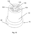
- FIG. 13 another perspective sectional view of a pressure sensor measuring element with structural elements on the inner wall of the sleeve and on the outer wall of the plunger.
- FIG. 1 in order to explain a production method for producing a pressure sensor measuring element.
- a generative production process is used in the production method.
- a model of a pressure sensor element existing in a control system 56 e.g. as a software file, is generated physically without the necessity of special tools and shaping devices by selective solidification of powder material 21 , in particular metal powder 22 , which is located in a layer 32 in a powder bed 24 .
- FIG. 1 shows a production device 10 for carrying out the generative production method for producing the pressure sensor measuring element.
- the production device 10 comprises a process chamber 12 , a material supply device 14 for providing material to be processed in layers, for example from a powder supply 18 , a beam generating device 36 for generating a processing beam 42 , and the control system 56 .
- the powder bed 24 which has a movable powder bed bottom 26 , which after processing a layer 32 is moved downwards by the corresponding processed layer thickness of the respective last pass.
- the powder bed bottom 26 is preferably in an upper position 28 .
- the material supply device 14 has a powder application device 20 , which in particular is designed in such a way that after processing of a layer 32 by this, a new layer 32 to be processed from the powder supply 18 is applied to the powder bed 24 again.
- the powder application device 20 can be, for example, a layer distribution slide 30 or a filling device 16 .
- the layer distribution slide 30 is in a waiting position in the region of the material supply device 14 , which is not in the processing beam region.
- the layer distribution slide 30 is only an example for the powder application device 20 , further powder application devices can also be used, e.g. powder nozzles for selective powder application, etc.
- the work piece 34 to be produced is produced in layers in the powder bed 24 .
- the beam generating device 36 has a beam generating unit 38 as well as at least one beam influencing device 46 .
- the beam generating unit 38 generates a processing beam 42 sufficient for processing.
- the processing beam 42 can be a laser or electron beam.
- the beam generating device 36 has a light fiber 40 for guiding a processing beam 42 designed as a laser beam.
- the beam influencing device 46 is designed in particular for directing, focusing or otherwise influencing the processing radiation.
- the beam influencing device 46 for example, has a lens 44 , and the beam influencing device 46 , for example, performs focusing movements 48 .
- the beam generating device 38 can be moved in one plane by means of a beam generating unit moving device 62 through the control system 56 and beam generating unit displacing movements 64 can be performed.
- Process chamber 12 is separated from the environment by a protective device 50 .
- the protective device can, for example, be made of glass or other materials by means of a protective pane 52 that is transparent to laser radiation.
- the control system 56 allows the beam generating device 36 to move in such a way that certain areas of the material layer 32 to be processed are irradiated in order to the subject the material to primary molding (e.g. melting or sintering the powder) at the required areas, e.g. at the radiation impact point 54 , and to form the work piece 34 .
- the powder bed bottom 26 is moved downwards and the powder application device 20 applies a new layer of material over the previously processed layer 32 for selective re-irradiation. For example, this can be done by the layer distribution slide 30 moving over the powder bed 24 .
- the control system 56 can be a data processing system 58 , for example a CAD system or similar system that is connected to the units to be controlled of the production device 10 via a control line 60 .
- a steel material, a stainless steel material and/or a NiCrNbMo alloy are particularly suitable as powder material 22 , whereby the latter materials have particular advantages with regard to corrosion resistance.
- Sensors made of such materials are used, for example, in marine diesel engines. For reasons of cost, heavy oils or the like are burned in them. If heavy oils are burned in cold engines, residues arise which are particularly problematic with regard to corrosion of the engine components.
- Examples of generative production methods suitable for producing the pressure sensor element may include selective laser sintering, laminated object manufacturing, fused deposition modeling, solid ground curing, and 3D print-like processes.
- a pressure sensor measuring element 66 can be produced in layers as a work piece, which will be explained in more detail below using the remaining Figures.
- FIG. 2 shows a preferred application of the pressure sensor element 66 .
- the pressure sensor element 66 has a first end 70 and a second end 72 .
- the pressure sensor element 66 is directly connected to a measuring chamber 74 with the first end 70 ahead.
- the measuring chamber 74 can be a combustion chamber 76 of an internal combustion engine.
- the first end 70 can therefore be a side facing the combustion chamber and the second end 72 a side facing away from the combustion chamber.
- the pressure sensor measuring element 66 is designed in particular for combustion chamber monitoring of an internal combustion engine, such as a marine engine (driven, for example, by heavy fuel oil or diesel), diesel engines for construction machinery and motor vehicles or a gasoline engine for motor vehicles and the like, as well as in areas of high-temperature applications such as monitoring turbines, for example pressure measurement within a hot steam turbine and injection molding machines.
- an internal combustion engine such as a marine engine (driven, for example, by heavy fuel oil or diesel), diesel engines for construction machinery and motor vehicles or a gasoline engine for motor vehicles and the like, as well as in areas of high-temperature applications such as monitoring turbines, for example pressure measurement within a hot steam turbine and injection molding machines.
- Such pressure sensor elements 66 are also suitable for measurements on corrosive media such as those found in process technology in the chemical industry.
- a pressure 84 can be measured online during operation of a plant or machine to be monitored, in particular a combustion chamber pressure can be measured online during operation of the combustion engine.
- the pressure signal can be used to control and regulate the operation of an engine, such as an internal combustion engine, and the operation and function of the engine, such as an internal combustion engine in particular, can be monitored.
- further sensor elements 122 of the pressure measuring element 66 which will be explained in more detail later in the description, it is also possible to output pressure and temperature differences.
- a temperature difference 82 between the first end 70 and the second end 72 of the pressure measuring element 66 is recorded.
- a temperature difference measuring element for example, can also be used for this purpose. This can be used to obtain a sensor that detects a temperature channel and/or a temperature conduction.
- FIGS. 3 to 5 an embodiment of the pressure sensor measuring element 66 is described, which can be produced with the production device 10 previously described with reference to FIG. 1 .
- the pressure sensor element 66 has a pressure measuring cell 68 and a force measuring element 88 .
- the pressure measuring cell 68 is manufactured in one piece using the generative production process.
- the pressure measuring cell 68 consists of a membrane-plunger unit 114 and a sleeve 94 .
- the membrane-plunger unit 114 has a first membrane or measuring membrane facing the measuring chamber 74 in the form of a separating membrane 92 which is connected by means of a plunger 108 to a second membrane 112 facing away from the measuring chamber 74 in such a way that movements of the separating membrane 92 are transmitted to the second membrane.
- the membrane 92 , 112 and the plunger 108 form the membrane-plunger unit 114 , which is housed inside the sleeve 94 .
- the sleeve 94 is not post-processed.
- the force measuring element 88 is designed in particular as a bending beam 90 with strain gauges.
- the sleeve 94 is essentially cylindrical. At the first end 70 , the sleeve 94 has a radially extending flange 86 on its outer circumference, which is flush with the separating membrane 92 .
- the separating membrane 92 can be influenced in its membrane properties by structuring or by changes to the geometry. In one design, the flange 86 is not post-processed.
- the pressure measuring cell 68 is described in more detail below with reference to FIGS. 4 and 5 .
- the pressure measuring cell 68 has only one component or part, namely the one-piece unit consisting of the sleeve 94 , the separating membrane 92 , the plunger 108 and the membrane 112 at the second end 72 .
- the sleeve 94 and the plunger 108 have a smooth surface in the inner area between an outer wall 110 of the plunger 108 and an inner wall 106 of the sleeve 94 .
- the pressure measuring cell 68 is produced using the generative production method.
- the bending beam 90 is attached to the second membrane 112 .
- unprocessed, loose powder material 22 remains in the cavity 104 between plunger 108 and inner wall 106 of the sleeve as a result of the generative production method, wherein the at least one powder outlet opening 96 is closed as a result of producing tightness of the pressure measuring cell 68 after the loose material powder 22 has been removed, for example by a closure ring 98 .
- the at least one powder outlet opening 96 should have a sufficient diameter so that the material powder can be completely removed.
- the closure ring 98 is applied to close the powder outlet opening 96 and, as shown in FIG.
- the pressure measuring cell 68 has an axially extending shoulder 102 with a smaller diameter than the sleeve in the area of the second end 72 .
- the closing ring 98 is pushed onto this closing ring shoulder 102 .
- the separating membrane 92 merges into the wall of the sleeve 94 in the outer radial circumference in the ring membrane area 118 .
- membrane 112 at the second end 72 the same applies to membrane 112 at the second end 72 .
- a channel 120 is provided inside plunger 108 , which extends from the first end to the second end of pressure measuring cell 68 and into which at least one further sensor element 122 can be inserted.
- Sensor element 122 can, for example, be a resistance sensor or a temperature sensor.
- Structural elements 136 are partially represented by the sectional view.
- the structural elements 136 are arranged radially along the entire circumference of the inner wall of the sleeve 106 and run axially. Size, number and design of the structural elements 136 are exemplarily shown in all Figures and can vary depending on the necessity of influencing the respective parameter.
- the structural elements 136 serve to influence various parameters such as stiffness, temperature conduction and resonance frequency and can be attached to the respective component in the form of ribs 138 .
- FIG. 5 shows a different section plane from FIG. 4 , from which it can be seen that the channel 120 extends to the first end 70 of the pressure measuring line 68 and at least one opening 132 is suitable for passing through a further sensor, i.e. in particular the temperature sensor.
- opening 132 is reworked, e.g. re-drilled to a diameter of 0.2 mm.
- FIG. 6 shows the same cutting plane as FIG. 5 .
- the additional sensor element 122 in FIG. 6 is now inserted into channel 120 of plunger 108 of the pressure measuring cell 68 .
- the at least one opening 132 can be seen in a separating membrane-plunger transition area 116 , into which at least one sensor tip 130 of the additional sensor element 122 is positioned.
- the sensor tip 130 is flush with the separating membrane 92 .
- Tightness can be achieved by connecting the sensor tip 130 and the separating diaphragm 92 , for example by welding.
- the sensor tip 130 is thus positioned close to the measuring chamber 74 , which can represent, for example, the combustion chamber temperature T B 78 of the combustion chamber 76 .
- the sensor element 122 can also be used to check the surface structure of the separating membrane 92 .
- Elements can also be attached to the membrane to monitor the membrane structure or function of the separating membrane 92 .
- One example is the attachment of a resistor to the inside of the separating membrane 92 . This allows cracks in the separating membrane 92 to be monitored. If a crack occurs in the separating membrane 92 , the electrical resistance changes.
- Such a resistor could be manufactured in such a way that at the time when the corresponding layer has to be built, a different powder material is applied to provide the material for the resistor.
- FIG. 7 shows a top view of the pressure measuring cell 68 .
- the openings for inserting 132 the additional sensor element 122 and an associated signal line 124 or connection line 126 are visible.
- the lines 124 , 126 can be led at the second end 72 through line through openings 128 out of the pressure measuring cell 68 to processing electronics (not shown).
- FIGS. 8 and 9 show the production state of the pressure measuring cell 68 after production, after the powder material 22 has been removed through the at least one powder outlet opening 96 .
- the powder outlet opening 96 is arranged in the area of the second end 72 .
- FIG. 10 A second embodiment is shown in FIG. 10 .
- this embodiment has no powder outlet openings 96 and the material powder 22 remains in the pressure measuring cell 68 . This can influence in particular the temperature channel.
- FIG. 11 shows a section in the area of the flange 86 .
- the pressure measuring cell 68 can have further transverse structures.
- the flange 86 has a heat shield 134 inside the pressure measuring cell. These structures reduce heat conduction from the side facing the combustion chamber to the side facing away from the combustion chamber. For this purpose, an FEM calculation can be made for the heat transfer calculation, for example. The introduction of such structures is possible in a generative production process.
- the channel 120 is arranged in the center of the pressure measuring cell 68 .
- FIGS. 12 and 13 Further designs and structural elements 136 of sleeve 94 and plunger 108 can be seen in FIGS. 12 and 13 .
- the pressure measuring cell 68 is cut in the area between the first end and the second end 72 , whereby the structural elements 136 in FIGS. 12 and 13 are exemplarily shown as stiffening ribs 138 .
- stiffening ribs 138 Further possibilities are, for example, the provision of channels in the wall or the production of further axial decoupling geometries.
- the outer shell which is subjected to mechanical stress, can be mechanically decoupled from the inner structure.
- Such stiffening ribs 136 can be used to influence resonance frequencies in particular.
- the interior of the pressure measuring cell 68 should be sealed to prevent the penetration of the combustion gas into the pressure measuring cell if the separating membrane 92 fails. Therefore, in a preferred design, the at least one powder outlet opening 96 is closed with a powder outlet opening closure ring 98 .
- the powder outlet opening closure ring 98 is seal-welded, for example using a laser welding process.
- the stainless steel grades with the material numbers 1.4542 and 1.4548 are particularly suitable for use with a pressure sensor measuring element when stainless steel is used.
- An important aspect of the invention concerns the combination of at least two sensors. This creates a combination sensor that measures pressure and temperature.
- pressure and temperature can be measured at the separating membrane 92 . It is also possible to output pressure and temperature difference. A temperature difference between the membrane side and the rear side is measured for this purpose. This can result in a sensor that detects a temperature channel or a temperature conduction.
- the generative production method offers particular advantages, which are explained below.
- the material selection (in particular Inconel 718—this material has particular advantages with regard to corrosion resistance) should be mentioned here.
- the background to this is that such sensors are used, for example, in marine diesel engines, in which heavy oils or the like are burned for cost reasons. If heavy oils are burned in cold engines, residues arise which are particularly problematic with regard to corrosion of the engine components.
- Another advantage of the invention refers to the shape of a pressure sensor.
- a particular difficulty of this type of pressure sensor is the production of special channel shapes, such as a central bore in particular. Such a central bore is more difficult to produce using machining techniques. The generative production process is predestined for this.
- thermocouple for cables, such as in particular a thermocouple or the like.
- Another possibility is, for example, to produce channels or axial decoupling geometries in the wall.
- the outer shell which is subjected to more mechanical stress, can be mechanically decoupled from the inner structure.
- stiffening ribs These are shown as examples in the Figures already explained. Such stiffening ribs can be used to influence resonance frequencies in particular. Thus a resonance frequency, which in the first drawing would be about 7 kilohertz without stiffening ribs, can be in the range of 20 kilohertz or higher.
- elements can be attached to the separating membrane 92 to monitor the membrane structure or the function of the separating membrane 92 .
- An example is the attachment of a resistor to the inside of the separating membrane 92 . This allows cracks in the separating membrane 92 to be monitored. If a crack occurs in the separating membrane 92 , the electrical resistance changes.
- the production process is then such that when the corresponding layer is to built, a different powder material is be applied to provide the material for the resistor.
- transverse structures such as the heat shield 134 .
- An FEM calculation for the heat transfer can be made here.
- the membrane is located in a combustion chamber of an engine, where the temperature has to be kept away from the electronics. It is possible with generative production technology to introduce corresponding structures that provide for less thermal conduction from the hot side to the cold side.
- the powder discharge openings should have a sufficiently large diameter so that the powder can be completely discharged. These openings can then be closed by a closure element—for example the powder outlet opening closure ring 98 .
- Another alternative design involves the powder material 21 remaining in the sensor.
- Possible applications are mainly planned for high-temperature applications such as combustion chamber monitoring, but also for injection molding machines and the monitoring of turbines such as a hot steam turbine, where the pressure is measured inside the turbine, for example. It is also possible to measure corrosive media, such as those found in process technology in the chemical industry.
- structuring of the separating membrane 92 can also be carried out.
- a slight angle can be provided in the membrane in a manner set back to the force element from the outside towards the center in order to improve the membrane properties.
- the invention provides, according to one aspect, a process for the production of a pressure sensor measuring element for a pressure sensor, which comprises at least one membrane and a sleeve supporting the membrane, the pressure sensor measuring element being produced in a layer-wise generative production process.
- a combination sensor for measuring pressure and a further parameter can have a simple structure.
- structures for stiffening or resonant frequency influencing or for heat conduction influencing can be introduced.
Landscapes
- Physics & Mathematics (AREA)
- Chemical & Material Sciences (AREA)
- Engineering & Computer Science (AREA)
- General Physics & Mathematics (AREA)
- Manufacturing & Machinery (AREA)
- Materials Engineering (AREA)
- Analytical Chemistry (AREA)
- Combustion & Propulsion (AREA)
- Plasma & Fusion (AREA)
- Mechanical Engineering (AREA)
- General Engineering & Computer Science (AREA)
- Measuring Fluid Pressure (AREA)
Abstract
Description
-
- 10 production device
- 12 process chamber
- 14 material supply device
- 16 filling device
- 18 powder supply
- 20 powder application device
- 21 powder material
- 22 metal powder
- 24 powder bed
- 26 powder bed bottom
- 28 upper position of powder bed
- 30 layer distribution slide
- 32 layer
- 34 work piece
- 36 beam generating device
- 38 beam generating unit
- 40 light fiber
- 42 processing beam
- 44 lens
- 46 beam influencing device
- 48 focusing movement
- 50 protective device
- 52 protective shield
- 54 radiation impingement point
- 56 control system
- 58 data processing system
- 60 control line
- 62 beam generating unit moving device
- 64 beam generating unit displacing movement
- 66 pressure sensor measuring element
- 68 pressure measuring cell
- 70 first end
- 72 second end
- 74 measuring chamber
- 76 combustion chamber
- 78 combustion chamber temperature TB
- 82 temperature difference ΔT
- 84 pressure
- 86 flange
- 88 force measuring element
- 90 bending bar
- 92 separating membrane (facing the combustion space)
- 94 sleeve
- 96 powder outlet opening
- 98 powder outlet opening closing ring
- 100 closing ring welding seam
- 102 closing ring shoulder
- 104 cavity
- 106 innerf wall of the sleeve
- 108 plunger
- 110 outer wall of the plunger
- 112 membrane (facing away from the combustion chamber)
- 114 membrane-plunger-unit
- 116 separating membrane-plunger transition zone
- 118 annular membrane region
- 120 channel
- 122 sensor element
- 124 signal line
- 126 connection line
- 128 line through opening
- 130 sensor tip
- 132 opening for sensor
- 134 heat shield
- 136 structural element
- 138 rib
Claims (14)
Applications Claiming Priority (3)
| Application Number | Priority Date | Filing Date | Title |
|---|---|---|---|
| DE102016124410.4 | 2016-12-14 | ||
| DE102016124410.4A DE102016124410A1 (en) | 2016-12-14 | 2016-12-14 | Method for producing a pressure sensor element as well as pressure sensor measuring element available therewith |
| PCT/EP2017/081912 WO2018108710A1 (en) | 2016-12-14 | 2017-12-07 | Method for producing a pressure sensor measuring element and thus obtained pressure sensor measuring element |
Publications (2)
| Publication Number | Publication Date |
|---|---|
| US20190360894A1 US20190360894A1 (en) | 2019-11-28 |
| US11137320B2 true US11137320B2 (en) | 2021-10-05 |
Family
ID=60935779
Family Applications (1)
| Application Number | Title | Priority Date | Filing Date |
|---|---|---|---|
| US16/469,914 Expired - Fee Related US11137320B2 (en) | 2016-12-14 | 2017-12-07 | Method for producing a pressure sensor measuring element and thus obtained pressure sensor measuring element |
Country Status (5)
| Country | Link |
|---|---|
| US (1) | US11137320B2 (en) |
| EP (1) | EP3555584A1 (en) |
| CN (1) | CN110476046B (en) |
| DE (1) | DE102016124410A1 (en) |
| WO (1) | WO2018108710A1 (en) |
Cited By (2)
| Publication number | Priority date | Publication date | Assignee | Title |
|---|---|---|---|---|
| US20210389198A1 (en) * | 2018-12-21 | 2021-12-16 | Exentis Knowledge Gmbh | Shaped article and method for producing a shaped article |
| US12320724B2 (en) | 2018-12-21 | 2025-06-03 | Exentis Knowledge Gmbh | Shaped body and method for producing a shaped body |
Families Citing this family (6)
| Publication number | Priority date | Publication date | Assignee | Title |
|---|---|---|---|---|
| DE102016225652A1 (en) * | 2016-12-20 | 2018-06-21 | Piezocryst Advanced Sensorics Gmbh | Method for producing a sensor housing for a force or pressure sensor and sensor housing, force or pressure sensor and use of an additive manufacturing device |
| EP3671160B1 (en) * | 2018-12-21 | 2024-07-31 | Exentis Knowledge GmbH | Mould and method for manufacturing the same |
| DE102020117587A1 (en) | 2020-07-03 | 2022-01-05 | IMES Intelligent Measuring Systems GmbH | Pressure transducer |
| DE102021110029A1 (en) * | 2021-04-21 | 2022-10-27 | anwerina AG | PROCESS FOR MANUFACTURING A MONOLITHIC COMPONENT |
| US12436049B2 (en) * | 2023-02-16 | 2025-10-07 | Te Connectivity Solutions Gmbh | Sensor die with a diaphragm |
| CN120119558B (en) * | 2025-05-14 | 2025-07-15 | 保利长大工程有限公司 | Cable-beam anchoring structure convenient to maintain in steel truss girder cable-stayed bridge |
Citations (9)
| Publication number | Priority date | Publication date | Assignee | Title |
|---|---|---|---|---|
| DE102005060652A1 (en) | 2005-12-19 | 2007-06-21 | Robert Bosch Gmbh | Combined pressure and temperature module for use with motor vehicles having a CO2 based air conditioning system has a pressure sensor arranged around a central temperature sensor |
| US20100002745A1 (en) * | 2006-09-15 | 2010-01-07 | Oliver Stoll | Sensor plug for combined pressure and temperature measurement |
| WO2010149501A1 (en) | 2009-06-26 | 2010-12-29 | Trafag Ag | Pressure sensor measuring element and pressure sensor which is provided with the latter and is intended to detect the pressure in a combustion chamber of an internal combustion engine |
| CN104907568A (en) | 2015-06-25 | 2015-09-16 | 武汉大学 | Piezoresistive thick film pressure sensor manufacturing method based on femtosecond laser composite technology |
| US20160103031A1 (en) | 2014-10-13 | 2016-04-14 | Endress + Hauser Gmbh + Co. Kg | Ceramic Pressure Sensor and Method for its Production |
| US20160109316A1 (en) | 2014-10-17 | 2016-04-21 | National Kaohsiung University Of Applied Sciences | Pressure detecting apparatus made by 3d printing technologies being able to be used in dangerous areas |
| US20160202101A1 (en) * | 2015-01-12 | 2016-07-14 | Douglas Ray Sparks | Sensor structures and methods of forming using three-dimensional printing techniques |
| US20180154484A1 (en) * | 2015-06-11 | 2018-06-07 | Renishaw Plc | Additive manufacturing apparatus and method |
| US20200232862A1 (en) * | 2016-12-20 | 2020-07-23 | Piezocryst Advanced Sensorics Gmbh | Method for producing a sensor housing for a power or pressure sensor and sensor housing, power or pressure sensor, and use of an additive production device |
Family Cites Families (14)
| Publication number | Priority date | Publication date | Assignee | Title |
|---|---|---|---|---|
| CN105209900B (en) * | 2013-01-02 | 2019-01-18 | 南洋理工大学 | sensor, its forming method and control method |
| EP3685941A1 (en) * | 2013-06-11 | 2020-07-29 | Renishaw PLC | Additive manufacturing apparatus and method |
| US9176016B2 (en) * | 2013-07-23 | 2015-11-03 | Lamplight Games | System and method for 3D printer material management |
| DE102013115007B4 (en) * | 2013-12-31 | 2016-07-14 | Trafag Ag | Density monitor with gear element and method for monitoring a gas density |
| IL246980B (en) * | 2014-02-01 | 2022-09-01 | Ezmems Ltd | Chip device for monitoring and regulating fluid flow, and methods of manufacture thereof |
| DE102014202020B4 (en) * | 2014-02-05 | 2016-06-09 | MTU Aero Engines AG | Method and device for determining residual stresses of a component |
| CN104236764B (en) * | 2014-09-29 | 2016-05-11 | 合肥工业大学 | A kind of capacitive touch sliding feeling sensor device |
| CN204422135U (en) * | 2015-02-06 | 2015-06-24 | 东西方(宁海)航空科技发展有限公司 | Integral type buffering valve |
| CN104960202B (en) * | 2015-06-29 | 2017-05-10 | 华中科技大学 | 3D printing device and method |
| CN105252000B (en) * | 2015-10-08 | 2017-09-19 | 湖南顶立科技有限公司 | A kind of metal dust increasing material manufacturing method under super-pressure inert gas shielding |
| CN105172152B (en) * | 2015-10-28 | 2017-06-20 | 深圳晗竣雅科技有限公司 | 3D forming methods based on profile injection moulding |
| CN105300574B (en) * | 2015-11-13 | 2018-04-17 | 常州二维碳素科技股份有限公司 | Graphene pressure sensor and its preparation method and application |
| CN105784208B (en) * | 2016-04-25 | 2018-06-05 | 西安电子科技大学 | A kind of disposable two-stage pressure sensor of 3D printing |
| CN106153243B (en) * | 2016-06-29 | 2019-03-29 | 中北大学 | Packaging method of MEMS turbulence sensor |
-
2016
- 2016-12-14 DE DE102016124410.4A patent/DE102016124410A1/en active Pending
-
2017
- 2017-12-07 US US16/469,914 patent/US11137320B2/en not_active Expired - Fee Related
- 2017-12-07 WO PCT/EP2017/081912 patent/WO2018108710A1/en not_active Ceased
- 2017-12-07 CN CN201780085303.XA patent/CN110476046B/en not_active Expired - Fee Related
- 2017-12-07 EP EP17825405.8A patent/EP3555584A1/en not_active Withdrawn
Patent Citations (9)
| Publication number | Priority date | Publication date | Assignee | Title |
|---|---|---|---|---|
| DE102005060652A1 (en) | 2005-12-19 | 2007-06-21 | Robert Bosch Gmbh | Combined pressure and temperature module for use with motor vehicles having a CO2 based air conditioning system has a pressure sensor arranged around a central temperature sensor |
| US20100002745A1 (en) * | 2006-09-15 | 2010-01-07 | Oliver Stoll | Sensor plug for combined pressure and temperature measurement |
| WO2010149501A1 (en) | 2009-06-26 | 2010-12-29 | Trafag Ag | Pressure sensor measuring element and pressure sensor which is provided with the latter and is intended to detect the pressure in a combustion chamber of an internal combustion engine |
| US20160103031A1 (en) | 2014-10-13 | 2016-04-14 | Endress + Hauser Gmbh + Co. Kg | Ceramic Pressure Sensor and Method for its Production |
| US20160109316A1 (en) | 2014-10-17 | 2016-04-21 | National Kaohsiung University Of Applied Sciences | Pressure detecting apparatus made by 3d printing technologies being able to be used in dangerous areas |
| US20160202101A1 (en) * | 2015-01-12 | 2016-07-14 | Douglas Ray Sparks | Sensor structures and methods of forming using three-dimensional printing techniques |
| US20180154484A1 (en) * | 2015-06-11 | 2018-06-07 | Renishaw Plc | Additive manufacturing apparatus and method |
| CN104907568A (en) | 2015-06-25 | 2015-09-16 | 武汉大学 | Piezoresistive thick film pressure sensor manufacturing method based on femtosecond laser composite technology |
| US20200232862A1 (en) * | 2016-12-20 | 2020-07-23 | Piezocryst Advanced Sensorics Gmbh | Method for producing a sensor housing for a power or pressure sensor and sensor housing, power or pressure sensor, and use of an additive production device |
Non-Patent Citations (2)
| Title |
|---|
| Faller, L.M. et al., "Robust Design of a 3D- and Inkjet-Printed Capacitive Force/Pressure Sensor", IEEE, 17th International Conference on Thermal, Mechanical and Multi-Physics Simulation and Experiments in Microelectronics and Microsystems, 7 pages (Apr. 18, 2016). |
| Lucklum, F. et al., "3D Printed Pressure Sensor with Screen-Printed Resistive Read-Out", Institute for Microsensors, -acuators, and -systems (IMSAS), Microsystems Center Bremen (MCB), University of Bremen, D-28359, Bremen, Germany, IEEE, 3 pages (Oct. 30, 2016). |
Cited By (3)
| Publication number | Priority date | Publication date | Assignee | Title |
|---|---|---|---|---|
| US20210389198A1 (en) * | 2018-12-21 | 2021-12-16 | Exentis Knowledge Gmbh | Shaped article and method for producing a shaped article |
| US12066349B2 (en) * | 2018-12-21 | 2024-08-20 | Exentis Knowledge Gmbh | Shaped article and method for producing a shaped article |
| US12320724B2 (en) | 2018-12-21 | 2025-06-03 | Exentis Knowledge Gmbh | Shaped body and method for producing a shaped body |
Also Published As
| Publication number | Publication date |
|---|---|
| WO2018108710A1 (en) | 2018-06-21 |
| DE102016124410A1 (en) | 2018-06-14 |
| CN110476046A (en) | 2019-11-19 |
| CN110476046B (en) | 2021-07-02 |
| EP3555584A1 (en) | 2019-10-23 |
| US20190360894A1 (en) | 2019-11-28 |
Similar Documents
| Publication | Publication Date | Title |
|---|---|---|
| US11137320B2 (en) | Method for producing a pressure sensor measuring element and thus obtained pressure sensor measuring element | |
| Kouprianoff et al. | Monitoring of laser powder bed fusion by acoustic emission: Investigation of single tracks and layers | |
| EP2777867B2 (en) | Methods for the repair of gas turbine engine components using additive manufacturing techniques | |
| US10900537B2 (en) | Vibration isolator assemblies and methods for the manufacture thereof | |
| US9835114B1 (en) | Freeform deposition method for coolant channel closeout | |
| EP3338919A1 (en) | Component with embedded sensor | |
| WO2017177070A1 (en) | Controlled camera off-axis alignment for the dynamic bore-surface-structure inspections via rotational/orbital/rotational orbiting angular off-axis controlled vision camera systems | |
| CN109414922B (en) | Method and thin-walled reinforcement structure for additive manufacturing | |
| EP3637111B1 (en) | Air data probe repair | |
| Haley et al. | Review of in situ process monitoring for metal hybrid directed energy deposition | |
| US20160258792A1 (en) | Conduit | |
| EP3587005A1 (en) | Control method for layerwise additive manufacturing, computer program product and control apparatus | |
| Liu et al. | Stereo vision-based repair of metallic components | |
| US9879566B2 (en) | Turbine engine couplings and methods for manufacturing turbine engine couplings | |
| Patel et al. | Design and additive manufacturing considerations for liquid rocket engine development | |
| Tanigawa et al. | Development of metal AM technology for gas turbine components | |
| Urbanic et al. | Material bead deposition with 2+ 2 ½ multi-axis machining process planning strategies with virtual verification for extruded geometry | |
| Farshidianfar | Control of microstructure in laser additive manufacturing | |
| Muktadir et al. | Additive manufacturing and acoustic Emission: a brief review | |
| WO2015057304A1 (en) | Panel with cooling holes and methods for fabricating same | |
| US10471542B1 (en) | Cladding and freeform deposition for coolant channel closeout | |
| Bremen et al. | Laser Powder Bed Fusion (LPBF) | |
| Nag et al. | In-Situ Monitoring Assisted Large-Scale Additive Manufacturing of Mild Steel and 316L Alloys for Nuclear Application | |
| Sohn et al. | NDE in metal additive manufacturing: Survey | |
| GB2521048A (en) | Conduit |
Legal Events
| Date | Code | Title | Description |
|---|---|---|---|
| FEPP | Fee payment procedure |
Free format text: ENTITY STATUS SET TO UNDISCOUNTED (ORIGINAL EVENT CODE: BIG.); ENTITY STATUS OF PATENT OWNER: SMALL ENTITY |
|
| FEPP | Fee payment procedure |
Free format text: ENTITY STATUS SET TO SMALL (ORIGINAL EVENT CODE: SMAL); ENTITY STATUS OF PATENT OWNER: SMALL ENTITY |
|
| AS | Assignment |
Owner name: TRAFAG AG, SWITZERLAND Free format text: ASSIGNMENT OF ASSIGNORS INTEREST;ASSIGNORS:STAIGER, ULRICH;STARK, DANIEL;ACHIM, PAHLKE;AND OTHERS;SIGNING DATES FROM 20190709 TO 20190720;REEL/FRAME:050116/0085 |
|
| STPP | Information on status: patent application and granting procedure in general |
Free format text: NON FINAL ACTION MAILED |
|
| STPP | Information on status: patent application and granting procedure in general |
Free format text: RESPONSE TO NON-FINAL OFFICE ACTION ENTERED AND FORWARDED TO EXAMINER |
|
| STPP | Information on status: patent application and granting procedure in general |
Free format text: NOTICE OF ALLOWANCE MAILED -- APPLICATION RECEIVED IN OFFICE OF PUBLICATIONS |
|
| STPP | Information on status: patent application and granting procedure in general |
Free format text: PUBLICATIONS -- ISSUE FEE PAYMENT RECEIVED |
|
| STPP | Information on status: patent application and granting procedure in general |
Free format text: PUBLICATIONS -- ISSUE FEE PAYMENT VERIFIED |
|
| STCF | Information on status: patent grant |
Free format text: PATENTED CASE |
|
| FEPP | Fee payment procedure |
Free format text: MAINTENANCE FEE REMINDER MAILED (ORIGINAL EVENT CODE: REM.); ENTITY STATUS OF PATENT OWNER: SMALL ENTITY |
|
| LAPS | Lapse for failure to pay maintenance fees |
Free format text: PATENT EXPIRED FOR FAILURE TO PAY MAINTENANCE FEES (ORIGINAL EVENT CODE: EXP.); ENTITY STATUS OF PATENT OWNER: SMALL ENTITY |
|
| STCH | Information on status: patent discontinuation |
Free format text: PATENT EXPIRED DUE TO NONPAYMENT OF MAINTENANCE FEES UNDER 37 CFR 1.362 |
|
| FP | Lapsed due to failure to pay maintenance fee |
Effective date: 20251005 |