US11136207B2 - Enclosure and dust capture and reclamation system and assembly for a traditional roller conveyor - Google Patents
Enclosure and dust capture and reclamation system and assembly for a traditional roller conveyor Download PDFInfo
- Publication number
- US11136207B2 US11136207B2 US16/998,308 US202016998308A US11136207B2 US 11136207 B2 US11136207 B2 US 11136207B2 US 202016998308 A US202016998308 A US 202016998308A US 11136207 B2 US11136207 B2 US 11136207B2
- Authority
- US
- United States
- Prior art keywords
- assembly
- conveyor belt
- roller assemblies
- idler roller
- rubber conveyor
- Prior art date
- Legal status (The legal status is an assumption and is not a legal conclusion. Google has not performed a legal analysis and makes no representation as to the accuracy of the status listed.)
- Active
Links
Images


Classifications
-
- B—PERFORMING OPERATIONS; TRANSPORTING
- B65—CONVEYING; PACKING; STORING; HANDLING THIN OR FILAMENTARY MATERIAL
- B65G—TRANSPORT OR STORAGE DEVICES, e.g. CONVEYORS FOR LOADING OR TIPPING, SHOP CONVEYOR SYSTEMS OR PNEUMATIC TUBE CONVEYORS
- B65G69/00—Auxiliary measures taken, or devices used, in connection with loading or unloading
- B65G69/18—Preventing escape of dust
- B65G69/181—Preventing escape of dust by means of sealed systems
-
- B—PERFORMING OPERATIONS; TRANSPORTING
- B65—CONVEYING; PACKING; STORING; HANDLING THIN OR FILAMENTARY MATERIAL
- B65G—TRANSPORT OR STORAGE DEVICES, e.g. CONVEYORS FOR LOADING OR TIPPING, SHOP CONVEYOR SYSTEMS OR PNEUMATIC TUBE CONVEYORS
- B65G21/00—Supporting or protective framework or housings for endless load-carriers or traction elements of belt or chain conveyors
- B65G21/08—Protective roofs or arch supports therefor
-
- B—PERFORMING OPERATIONS; TRANSPORTING
- B65—CONVEYING; PACKING; STORING; HANDLING THIN OR FILAMENTARY MATERIAL
- B65G—TRANSPORT OR STORAGE DEVICES, e.g. CONVEYORS FOR LOADING OR TIPPING, SHOP CONVEYOR SYSTEMS OR PNEUMATIC TUBE CONVEYORS
- B65G33/00—Screw or rotary spiral conveyors
- B65G33/08—Screw or rotary spiral conveyors for fluent solid materials
-
- B—PERFORMING OPERATIONS; TRANSPORTING
- B65—CONVEYING; PACKING; STORING; HANDLING THIN OR FILAMENTARY MATERIAL
- B65G—TRANSPORT OR STORAGE DEVICES, e.g. CONVEYORS FOR LOADING OR TIPPING, SHOP CONVEYOR SYSTEMS OR PNEUMATIC TUBE CONVEYORS
- B65G39/00—Rollers, e.g. drive rollers, or arrangements thereof incorporated in roller-ways or other types of mechanical conveyors
- B65G39/10—Arrangements of rollers
- B65G39/12—Arrangements of rollers mounted on framework
- B65G39/18—Arrangements of rollers mounted on framework for guiding loads
-
- B—PERFORMING OPERATIONS; TRANSPORTING
- B65—CONVEYING; PACKING; STORING; HANDLING THIN OR FILAMENTARY MATERIAL
- B65G—TRANSPORT OR STORAGE DEVICES, e.g. CONVEYORS FOR LOADING OR TIPPING, SHOP CONVEYOR SYSTEMS OR PNEUMATIC TUBE CONVEYORS
- B65G69/00—Auxiliary measures taken, or devices used, in connection with loading or unloading
- B65G69/18—Preventing escape of dust
- B65G69/185—Preventing escape of dust by means of non-sealed systems
- B65G69/188—Preventing escape of dust by means of non-sealed systems with spraying means
-
- B—PERFORMING OPERATIONS; TRANSPORTING
- B65—CONVEYING; PACKING; STORING; HANDLING THIN OR FILAMENTARY MATERIAL
- B65G—TRANSPORT OR STORAGE DEVICES, e.g. CONVEYORS FOR LOADING OR TIPPING, SHOP CONVEYOR SYSTEMS OR PNEUMATIC TUBE CONVEYORS
- B65G21/00—Supporting or protective framework or housings for endless load-carriers or traction elements of belt or chain conveyors
- B65G21/20—Means incorporated in, or attached to, framework or housings for guiding load-carriers, traction elements or loads supported on moving surfaces
- B65G21/2045—Mechanical means for guiding or retaining the load on the load-carrying surface
- B65G21/2063—Mechanical means for guiding or retaining the load on the load-carrying surface comprising elements not movable in the direction of load-transport
- B65G21/2072—Laterial guidance means
- B65G21/2081—Laterial guidance means for bulk material, e.g. skirts
-
- B—PERFORMING OPERATIONS; TRANSPORTING
- B65—CONVEYING; PACKING; STORING; HANDLING THIN OR FILAMENTARY MATERIAL
- B65G—TRANSPORT OR STORAGE DEVICES, e.g. CONVEYORS FOR LOADING OR TIPPING, SHOP CONVEYOR SYSTEMS OR PNEUMATIC TUBE CONVEYORS
- B65G2201/00—Indexing codes relating to handling devices, e.g. conveyors, characterised by the type of product or load being conveyed or handled
- B65G2201/04—Bulk
- B65G2201/042—Granular material
-
- B—PERFORMING OPERATIONS; TRANSPORTING
- B65—CONVEYING; PACKING; STORING; HANDLING THIN OR FILAMENTARY MATERIAL
- B65G—TRANSPORT OR STORAGE DEVICES, e.g. CONVEYORS FOR LOADING OR TIPPING, SHOP CONVEYOR SYSTEMS OR PNEUMATIC TUBE CONVEYORS
- B65G33/00—Screw or rotary spiral conveyors
- B65G33/08—Screw or rotary spiral conveyors for fluent solid materials
- B65G33/10—Screw or rotary spiral conveyors for fluent solid materials with non-enclosed screws
Definitions
- Dust collection equipment and methodologies for controlling dust and material spillage associated with the operation of a conveyor system for transporting wet or high moisture content bulk materials is described herein.
- Dust formation from a variety of sources has been a continuing cause of environmental and health concerns. Particular attention has been paid to the dust developed from the handling of coal, but such sources also include, for example, petroleum coke, recycled glass dust and bauxite. Thus, while in this specification, reference is often made to coal, it should be understood that this discussion is applicable to numerous other dust sources as well.
- a dust capture and reclamation system for a rubber conveyor belt having a loading side for moving granular material in a first direction, and a return side moving in a second direction opposed to the first direction.
- the system has a housing for mounting over a portion of the rubber conveyor belt.
- the housing has a top wall and a pair of opposed side walls.
- the side walls define a passage connecting an entrance to an exit.
- the passage is dimensioned to accommodate the rubber conveyor belt.
- the system further has a plurality of idler roller assemblies to be positioned inside the housing for supporting a portion of the loading side of the rubber conveyor belt.
- the system also has a plurality of return roller assemblies for supporting a portion of the return side of the belt.
- a trough is provided for mounting under the rubber conveyor belt to catch granular material falling therefrom.
- the trough has an inside surface and a mechanism is provided for moving granular material along the inside surface to a collection point.
- a first access panel is provided through one side wall of the pair of opposed side walls for accessing an idler roller assembly of the plurality of idler roller assemblies.
- a second access panel is provided through one of the pair of opposed side walls for accessing a return roller assembly of the plurality of return roller assemblies.
- a material capture and reclamation assembly for use with a rubber conveyor belt.
- the conveyor belt is entrained along an endless path and has a loading side and a return side.
- the assembly includes a housing having a top wall and a pair of opposed side walls. The opposed side wall define a passage connecting an entrance to an exit. The passage is dimensioned to enclose a portion of the rubber conveyor belt.
- a plurality of idler roller assemblies are positioned inside the housing. The idler roller assemblies are spaced from one another along the passage and support a portion of the loading side of the rubber conveyor belt.
- a plurality of return roller assemblies are positioned inside the housing and are spaced from one another along the passage for supporting a portion of the return side of the belt.
- a trough is positioned under the rubber conveyor belt to catch granular material falling from the rubber conveyor belt, and the trough has an inside surface.
- the assembly has a mechanism for moving granular material along the inside surface to a collection point.
- a first access panel is provided through one side wall of the pair of opposed side walls for accessing an idler roller assembly of the plurality of idler roller assemblies.
- a second access panel is provided through one of the pair of opposed side walls for accessing a return roller assembly of the plurality of return roller assemblies.
- FIG. 1 is a side elevation view of a rubber conveyor belt with an enclosure, and a dust and material capture and reclamation system and assembly of the present invention.
- FIG. 2 is the side elevation view of FIG. 1 with panels removed from a side wall.
- FIG. 3 is a vertical cross-sectional view through a central portion of FIG. 1 .
- FIG. 4 is an enlarged perspective view of roller assemblies within the enclosure.
- FIG. 5 is a front elevation view of a roller assembly within the enclosure.
- FIG. 6 is a view of FIG. 1 with certain panels removed from the side walls and with inspection hatch doors open.
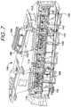
- FIG. 7 is a perspective view of the capture and reclamation system and assembly with several side panels removed and access door in an open condition.
- FIG. 8 is a perspective view in cross section showing a return roller
- FIG. 9 is a perspective view showing spray heads inside the housing
- FIG. 10 is an enlarged view of a skirtboard assembly inside the housing.
- FIG. 11 is a perspective view of a screw conveyor.
- FIG. 12 is a perspective view of a moving paddle conveyor.
- FIGS. 1-7 show a belt conveyor system 10 and a dust and granular material reclamation system, assembly, and enclosure 100 (dust reclamation system 100 for short) enclosing a portion of the conveyor system 10 .
- the dust reclamation unit 100 can be a standalone unit for retrofitting to an existing conveyor system 10 , or the dust reclamation system 100 can be manufactured or assembled and sold together with the belt conveyor system 10 as new equipment.
- the belt conveyor system 10 has a driving head pulley 12 , a tail pulley 14 , and an endless belt 16 entrained thereabout.
- the belt 16 has a loading side 18 for transporting granular material in a first direction as shown by arrow 20 and a return side 22 moving in a second direction opposite to the first direction shown by arrow 24 .
- An electric motor and gearbox turn the driving head pulley 12 .
- the belt 16 is pulled tight with a tensioning system to produce friction between it and the driving head pulley 12 . The friction overcomes the load and drag forces and the belt moves in the direction of the arrow 20 around the endless circuit from the tail pulley 14 to the head pulley 12 , loaded with material, and back to the tail pulley 16 empty of most material.
- the belt can be made of metal, rubber, plastic, composites, fabric, metal and combinations of any of these.
- the material conveyed on the conveyor belt includes granular, wet or high moisture content bulk materials including, for example, coal, petroleum coke, recycled glass, bauxite, grains, oilseeds, absorbent clay, borax, fertilizers among many others.
- the material can be friable i.e., easily crumbled to form dust and small particles.
- the material can be of varying granularity from particles having a width dimension that spans an entire width of the conveyor belt, on the large end of sizes, to medium sized particles having a width of two feet to about 12 inches, to medium-small particles having a width of less than 12 inches but greater than 3 inches, to small particles having a width of less than 3 inches but greater than 0.1 inches, to very small particles having a width dimension of less than 0.1 inches to a minimum level of detection such as 0.01 inches, 0.001 inches (thousandths of an inch), 0.0001 inches (ten thousandths of an inch), 0.00001 inches (hundred thousandths of an inch), and so on.
- the dust reclamation system 100 has a housing 102 for mounting over a portion of the rubber conveyor belt 16 .
- the housing 102 has a top wall 104 , a pair of opposed side walls 106 defining a passage 108 connecting an entrance 110 to an exit 112 .
- the housing 102 is shown having a flat top wall 104 to form a flat roof.
- the top wall 104 could be configured to form a gable roof, a hip roof, a dutch roof, a mansard roof, a shed roof, and a gambrel roof for example.
- the opposed side walls 106 are segmented having a bottom portion 126 and a top portion 128 .
- the top portion has removable panels 130 that can be removed to access the passage 112 to clean and service the system 100 and the idler roller assemblies 116 .
- a first panel 132 has three widows 134 to see inside the passage and a second panel 136 has two viewing windows 138 .
- the number, size, and shape of the windows can vary provided they allow for visual inspection from outside to inside of the housing.
- the panel is held in place by a pin or pins that can be removed by hand of an operator of the system and the panel lifted away to access the passage 112 .
- FIG. 4 shows the bottom portion of the side wall 126 has access doors 140 for servicing the return roller assemblies 116 .
- the access door 140 is mounted by a pair of hinges 154 to the sidewall and has a mechanism for locking and unlocking the door.
- the door can also have a handle 148 .
- the locking mechanism shown includes an arm 156 pivotally moveable from a locked condition to an unlocked condition.
- the arm 156 is moveable by a hand of an operator of the system without the use of a tool.
- the return roller assemblies 116 can be removed through the access door 140 for servicing and then returned into place through the open access door. The door can then be closed and locked during operation of the system.
- the bottom portion of side wall 126 also has through holes to define ports 142 .
- a fluid supply line 144 connects a source of liquid or gas under pressure (not shown) to a spray head 146 mounted inside the passage 112 ( FIG. 8 ). A portion of the fluid supply line passes through the port.
- the spray head 146 is mounted over the trough 118 and directs a pressurized stream of air or liquid onto the inside surface of the trough 120 to move granular material and dust therealong to the collection point 124 .
- Three ports 142 are shown but a fewer or a greater number of ports 142 could be provided.
- the spray heads can direct spray can direct spray in any direction desired including in the same direction as the belt is moving, in an opposite direction of belt direction, directly downward, at an acute angle to the belt direction, an obtuse angle, or perpendicular to the belt direction.
- FIG. 4 shows the plurality of idler roller assemblies 106 are spaced from one another and are mounted in alignment between the head and tail drive rollers 14 , 16 .
- Each idler roller assembly 106 has a set of three roller assemblies—two lateral idler roller assemblies 152 flanking a central roller assembly 150 .
- the rail 158 extends cross wise through the passage and is mounted at opposed ends to the housing 102 .
- Each roller assembly 150 , 152 can be slid along the rail 158 from an operating position as shown in FIG. 4 , inside the housing, to a service position outside of the housing.
- the idler roller assemblies 150 , 152 can be serviced after removal of the respective removable side wall panel 130 .
- each idler assembly can be secured to the rail using threaded fasteners or other securing mechanism.
- the centrally disposed roller assembly 150 has a roller 160 that rotates about a first axis of rotation parallel to a line drawn perpendicular across a width of the conveyor belt 12 .
- the lateral roller assemblies 152 have a lateral roller 162 that rotates about a second axis of rotation disposed at an acute angle to the first axis of rotation.
- the three roller assemblies 150 , 152 form a trough shaped support for the conveyor belt 16 ( FIG. 6 ).
- FIGS. 4-7 show two varieties of rollers.
- the first type of roller is known as an impact roller 164 .
- the impact roller 164 as best seen in FIG. 5 has a generally cylindrically shape with an outer surface in the form of a repeat pattern of square shaped valleys 166 and square shaped peaks 168 .
- the second type of roller is a standard roller 170 that is cylindrically shaped and has a smooth outer surface that has a constant diameter.
- the impact rollers 164 are placed in locations where granular material is dropped onto the belt 16 during a loading process.
- the standard rollers are placed in places where loading does not occur.
- FIGS. 5 and 8 show a return roller assembly 116 having a return roller 172 that spans the width of the conveyor belt and is slidably mounted on a rail 172 , similar to the idler roller assemblies.
- the return roller 172 is generally cylindrical and has an outer surface having a repeating pattern of square peaks 174 and square valleys 176 . At opposed ends 178 are square peaks 174 that have a greater axial dimension than the other square peaks.
- the return roller assemblies can be accessed through the access door 140 and slid out for servicing and slid into operating position by an operator of the system.
- the return roller assemblies are positioned below and in partial contact with the return side 22 of the belt 16 .
- FIG. 9 shows the trough 118 mounted under the rubber conveyor belt 16 to catch granular material falling therefrom.
- the trough 118 can be modular having numerous segments of trough panels mounted under the belt 16 . Individual trough panels can be removed for servicing without having to remove all of the trough panels.
- FIG. 10 shows an optional skirtboard assembly 200 that is mounted along lateral edges of the belt and inside the housing 102 to reduce spillage.
- the skirtboard is adjustable as shown by the arrows 202 to various levels of height above the loading side 18 of the belt.
- One suitable skirtboard assembly is sold by Benetech under the trademark MaxZone® 150.
- the loading chutes have a generally rectangular housing defining an internal passageway for directing the grain from a top end 182 of the chute to a bottom end 184 of the chute. A portion of the top wall 104 is removed to form a hole to allow grain to flow through the chutes onto the belt 16 .
- the chutes have inspection doors 186 near the top of the chutes. The inspection doors are moveable from an open condition to a closed condition as needed to service the chute.
- An unloading chute 188 is provided at one end of the system 100 where granular material is offloaded from the belt for storage or for transport elsewhere.
- the dust reclamation system 100 have a plurality of legs 190 supporting the system.
- the legs 190 can have varying lengths or can be adjustable for leveling and adjusting the slope to a desired degree the belt 16 travels with respect to a horizontal surface.
- the system 100 is shown at an angle of 16° but can be varied from 0° to 30°, more preferably from 0° to 20°, and most preferably from about 0° to 15°.
- FIG. 11 shows an alternative mechanism 122 for moving dust through the trough in the form of a screw conveyor 192 extending along a length of the conveyor belt 12 and powered by a motor not shown. Dust is conveyed out of the trough to a collection location not shown.
- FIG. 12 shows another embodiment of the mechanism 122 for moving dust through the trough using a plurality of paddles 196 that move in reciprocating fashion as indicated by arrows 198 to direct bulk material to the collection area or container such as a sack or bag.
- dust recovery mechanisms 130 , 140 can be retrofitted to existing standard roller conveyor belt systems or be in included as part of the initial conveyance system when initially installed.
Abstract
Description
Claims (20)
Priority Applications (2)
| Application Number | Priority Date | Filing Date | Title |
|---|---|---|---|
| US16/998,308 US11136207B2 (en) | 2019-08-20 | 2020-08-20 | Enclosure and dust capture and reclamation system and assembly for a traditional roller conveyor |
| US17/410,825 US11518632B2 (en) | 2019-08-20 | 2021-08-24 | Enclosure and dust capture and reclamation system and assembly for a traditional roller conveyor |
Applications Claiming Priority (2)
| Application Number | Priority Date | Filing Date | Title |
|---|---|---|---|
| US201962889429P | 2019-08-20 | 2019-08-20 | |
| US16/998,308 US11136207B2 (en) | 2019-08-20 | 2020-08-20 | Enclosure and dust capture and reclamation system and assembly for a traditional roller conveyor |
Related Child Applications (1)
| Application Number | Title | Priority Date | Filing Date |
|---|---|---|---|
| US17/410,825 Continuation US11518632B2 (en) | 2019-08-20 | 2021-08-24 | Enclosure and dust capture and reclamation system and assembly for a traditional roller conveyor |
Publications (2)
| Publication Number | Publication Date |
|---|---|
| US20210053781A1 US20210053781A1 (en) | 2021-02-25 |
| US11136207B2 true US11136207B2 (en) | 2021-10-05 |
Family
ID=74646645
Family Applications (2)
| Application Number | Title | Priority Date | Filing Date |
|---|---|---|---|
| US16/998,308 Active US11136207B2 (en) | 2019-08-20 | 2020-08-20 | Enclosure and dust capture and reclamation system and assembly for a traditional roller conveyor |
| US17/410,825 Active US11518632B2 (en) | 2019-08-20 | 2021-08-24 | Enclosure and dust capture and reclamation system and assembly for a traditional roller conveyor |
Family Applications After (1)
| Application Number | Title | Priority Date | Filing Date |
|---|---|---|---|
| US17/410,825 Active US11518632B2 (en) | 2019-08-20 | 2021-08-24 | Enclosure and dust capture and reclamation system and assembly for a traditional roller conveyor |
Country Status (2)
| Country | Link |
|---|---|
| US (2) | US11136207B2 (en) |
| WO (1) | WO2021035041A1 (en) |
Cited By (2)
| Publication number | Priority date | Publication date | Assignee | Title |
|---|---|---|---|---|
| US11518632B2 (en) | 2019-08-20 | 2022-12-06 | Benetech, Inc. | Enclosure and dust capture and reclamation system and assembly for a traditional roller conveyor |
| US11919719B2 (en) | 2021-05-13 | 2024-03-05 | Benetech, Inc. | Drop and slide out idler assembly |
Families Citing this family (3)
| Publication number | Priority date | Publication date | Assignee | Title |
|---|---|---|---|---|
| CN114056969B (en) * | 2021-11-08 | 2023-11-07 | 北京华能新锐控制技术有限公司 | Closed dust suppression mechanism for coal conveying belt |
| CN117262799B (en) * | 2023-09-07 | 2024-03-29 | 扬州元益混凝土有限公司 | Concrete raw material conveying device with dust removal function |
| CN116946763B (en) * | 2023-09-20 | 2023-12-26 | 山西电之家科技有限公司 | Dry fog dust suppression device |
Citations (73)
| Publication number | Priority date | Publication date | Assignee | Title |
|---|---|---|---|---|
| US1047866A (en) | 1911-11-21 | 1912-12-17 | John Laing Weller | Device for spouting concrete, grain, and the like. |
| US1524334A (en) | 1920-09-23 | 1925-01-27 | Fairfield Eng Co | Adjustable revolving chute |
| US1789069A (en) | 1929-01-02 | 1931-01-13 | Cutler Hammer Inc | Controller for electric motors |
| US1791371A (en) | 1929-03-23 | 1931-02-03 | Fegles Construction Company Lt | Loading-spout device |
| US1800920A (en) | 1929-03-18 | 1931-04-14 | Wilson James Elliott | Making of bread |
| US1814619A (en) | 1929-02-19 | 1931-07-14 | Edward F Carter | Turnhead for dock spouts |
| US1896149A (en) * | 1926-11-13 | 1933-02-07 | Metalwash Machinery Co | Treating or washing machinery |
| US2219226A (en) | 1939-06-12 | 1940-10-22 | Addington W Gerber | Grain distribution |
| US2249588A (en) * | 1940-03-07 | 1941-07-15 | George A Waddle | Conveyer |
| US2859873A (en) | 1958-01-02 | 1958-11-11 | Phillips Petroleum Co | Equipment for manufacturing mixed fertilizers |
| US3248018A (en) | 1964-10-20 | 1966-04-26 | Martin M Fleischman | Dustproof drum closure and dispenser |
| US3259078A (en) | 1964-09-14 | 1966-07-05 | Pullman Inc | Trough hatch cover and operating mechanism |
| DE1531910A1 (en) | 1967-07-04 | 1970-01-15 | Engelbrecht & Lemmerbrock | Distributor head for conveyor blower |
| US3568819A (en) | 1969-02-24 | 1971-03-09 | Sperry Rand Corp | Mounting and drive for a horizontally and vertically swingable unloading feed conveyor |
| FR2207074A1 (en) | 1972-11-21 | 1974-06-14 | Tubes Pneumatiques Soc | |
| US3858733A (en) | 1971-12-24 | 1975-01-07 | Ishikawajima Harima Heavy Ind | Device for loading bulk materials |
| DE2404157A1 (en) | 1974-01-29 | 1975-07-31 | Kaiser Preussag Aluminium Gmbh | Bulk material filling mechanism - has hinged filling chute in two sections working with discharge shutter |
| US3926290A (en) | 1974-03-04 | 1975-12-16 | Mitsui Shipbuilding Eng | Loading chute for cargo vessel |
| US4039062A (en) | 1974-11-28 | 1977-08-02 | Air-Industrie | Flow divider for a powdery material |
| NL7803864A (en) | 1977-04-15 | 1978-10-17 | Stanelle Karl Heinz | FILLER. |
| US4164327A (en) | 1978-04-07 | 1979-08-14 | Clark Donald Y | Grain spreader |
| US4177736A (en) | 1977-11-28 | 1979-12-11 | Pullman Incorporated | Mechanically and weldingly secured bracket |
| DE2927316B1 (en) | 1979-07-06 | 1980-02-21 | Demag Ag Mannesmann | Distribution device for top closures of shaft ovens, especially for blast furnace top closures |
| DE3023898A1 (en) | 1980-06-26 | 1982-01-21 | Stetter Gmbh, 8940 Memmingen | Adjustable suspension of worm conveyor on storage silo - uses cardan or flexible adjustable inlet and outlet section with outlet section axis eccentrically offset relative to axis of storage silo |
| JPS5747123A (en) | 1980-09-03 | 1982-03-17 | Tsuneyuki Iwata | Supplying method of hot air for drying unhulled rice |
| EP0062769A1 (en) | 1981-04-03 | 1982-10-20 | Paul Wurth S.A. | Method of actuating an oscillating chute in a receptacle under pressure, device for carrying out such a method and shaft furnace charging installation with such a device |
| US4363350A (en) | 1980-11-03 | 1982-12-14 | Beckerer Frank S | Self-draining boat window |
| US4489862A (en) | 1981-01-31 | 1984-12-25 | Hubert Eirich | Device for the controllable removal of bulk materials from containers |
| KR850005816A (en) | 1984-02-13 | 1985-09-26 | 데니스 앰. 맥윌리엄즈 | Kenvey Belt Cleaner (CLEANER) |
| US4552573A (en) | 1982-03-12 | 1985-11-12 | Cargill Incorporated | Dust suppressor apparatus |
| US4603769A (en) | 1984-07-16 | 1986-08-05 | Bert Bach | Grain chute system |
| US4623056A (en) | 1983-09-30 | 1986-11-18 | The Dow Chemical Company | Apparatus for distributing material flow |
| US4643293A (en) * | 1984-02-13 | 1987-02-17 | Martin Engineering Company | Conveyor belt cleaner |
| US4775267A (en) | 1987-02-12 | 1988-10-04 | Nisso Engineering Co., Ltd. | Pneumatic conveyor for powder |
| US4878576A (en) * | 1987-09-28 | 1989-11-07 | Dietzen Gary H | Method for accumulating and containing bore hole solids and recovering drill fluids and waste water on drilling rigs |
| EP0369605A1 (en) | 1988-10-14 | 1990-05-23 | Martin Engineering Company | Conveyor skirt board, clamp and mounting arrangement |
| US5024319A (en) | 1989-10-18 | 1991-06-18 | Dixon Steven C | Belt heater for conveyors |
| US5123542A (en) | 1991-06-03 | 1992-06-23 | Hoppe Gerald W | Method and apparatus for cleaning, distributing and aerating grain |
| US5160222A (en) | 1990-11-30 | 1992-11-03 | Tech-Air, Inc. | Pneumatic conveying system |
| US5190132A (en) | 1987-08-19 | 1993-03-02 | Karl-Heinz Stanelle | System for loading a silo vehicle or similar with pourable bulk material |
| US5248344A (en) | 1991-06-03 | 1993-09-28 | Hoppe Gerald W | Method for cleaning, distributing and aerating grain |
| EP0584441A1 (en) | 1992-08-25 | 1994-03-02 | Hartung, Kuhn & Co. Maschinenfabrik Gmbh | Device for filling coal into the oven chambers of a coke oven battery |
| US5368192A (en) | 1993-04-27 | 1994-11-29 | Sweeney Enterprises, Inc. | Food pellet dispensing apparatus |
| US5372229A (en) | 1991-03-14 | 1994-12-13 | Th. Rasmussen Molle- Og Maskinbyggeri A/S | Device for delivering flowable bulk cargo |
| US5441321A (en) | 1991-09-02 | 1995-08-15 | Karpisek; Ladislav S. | Openable container base |
| US5697408A (en) | 1994-04-30 | 1997-12-16 | Reeves; Leslie Neville | Filling containers |
| US5697375A (en) | 1989-09-18 | 1997-12-16 | The Research Foundation Of State University Of New York | Method and apparatus utilizing heart sounds for determining pressures associated with the left atrium |
| US5769573A (en) | 1992-04-01 | 1998-06-23 | Rieter Machine Works, Ltd. | Apparatus for controlling air flow in an air duct |
| US5993117A (en) | 1996-01-29 | 1999-11-30 | Servend International, Inc. | Ice transportation system and method |
| US6102195A (en) * | 1999-03-26 | 2000-08-15 | Weikel; Charles W. | Belt conveyor |
| EP1129965A2 (en) | 2000-03-04 | 2001-09-05 | Krupp Fördertechnik GmbH | Device for transferring pulverulent products |
| US6578694B2 (en) | 2001-02-16 | 2003-06-17 | Mcneilus Truck And Manufacturing, Inc. | Discharge chute control system |
| US6681921B1 (en) * | 2002-09-30 | 2004-01-27 | Intersystems, A Division Of Enduro Systems, Inc. | Enclosed belt conveyor assembly |
| US6827025B2 (en) | 2003-03-26 | 2004-12-07 | Miner Enterprises, Inc. | Hatch cover for a railroad hopper car |
| US6921037B2 (en) | 2003-04-17 | 2005-07-26 | Finn Corporation | Adjustable discharge apparatus |
| US7000758B2 (en) * | 2004-04-01 | 2006-02-21 | Bruks Ab | Conveyor system |
| US7003850B2 (en) | 2003-12-08 | 2006-02-28 | Miner Enterprises, Inc. | Railroad car hatch cover hinge structure and method for connecting a hatch cover to a railcar |
| US7028629B2 (en) | 2003-02-03 | 2006-04-18 | Richard Walcome | Self-sealing port light assembly |
| US20060151280A1 (en) | 2005-01-10 | 2006-07-13 | Benetech, Inc. | Bulk material precision transfer chute apparatus |
| US7364034B1 (en) | 2007-07-11 | 2008-04-29 | Benetech Inc. | Adjustable aperture apparatus that retains dust from bulk material directed through the apparatus |
| US7735620B2 (en) | 2008-09-22 | 2010-06-15 | Martin Engineering Company | Dust buildup resistant access door and door frame of a bulk material handling system |
| KR20110056815A (en) | 2009-11-23 | 2011-05-31 | 주식회사 대신우레탄 | Belt conveyor system having dust adsorption a removing device |
| US7958992B1 (en) | 2010-11-19 | 2011-06-14 | Stier Randal J | Inspection door with radiused coaming for dust control |
| US8727108B2 (en) * | 2011-05-13 | 2014-05-20 | Adrianus Dekoning | Belt conveyor for oilseeds |
| US8960419B2 (en) * | 2013-03-04 | 2015-02-24 | Kennedy Metal Products & Buildings, Inc. | Box check for conveyor belt and method of installation |
| US8967357B2 (en) * | 2013-06-13 | 2015-03-03 | Meridian Manufacturing Inc. | Grain auger blow-out door |
| KR20160056698A (en) | 2014-11-12 | 2016-05-20 | 주식회사 포스코 | Device for treating coal detached from belt of conveyor |
| US9598248B2 (en) * | 2012-01-31 | 2017-03-21 | Loewen Welding & Manufacturing Ltd. | Apparatus for loading material |
| US10246265B2 (en) * | 2017-01-12 | 2019-04-02 | Custom Agri Systems, Inc. | Belt conveyor system |
| US10676294B2 (en) * | 2011-09-09 | 2020-06-09 | Sioux Steel Company | Modular storage bin sweep system |
| US10766709B2 (en) * | 2017-02-08 | 2020-09-08 | Conveyor Manufacturers Australia Pty Ltd. | Modular conveyance system |
| US10926967B2 (en) | 2016-01-06 | 2021-02-23 | Sandbox Enterprises, Llc | Conveyor with integrated dust collector system |
| WO2021035041A1 (en) | 2019-08-20 | 2021-02-25 | Benetech, Inc. | Enclosure and dust capture and reclamation system and assembly for a traditional roller conveyor |
Family Cites Families (4)
| Publication number | Priority date | Publication date | Assignee | Title |
|---|---|---|---|---|
| US4714151A (en) * | 1986-04-30 | 1987-12-22 | Cambelt International Corporation | Apparatus for supporting and enclosing conveyor systems |
| US6293389B1 (en) * | 2000-02-08 | 2001-09-25 | William L. McLean | En masse bulk material conveyor apparatus |
| US11066259B2 (en) | 2016-08-24 | 2021-07-20 | Halliburton Energy Services, Inc. | Dust control systems for bulk material containers |
| US11383933B2 (en) * | 2018-06-12 | 2022-07-12 | Thyssenkrupp Industrial Solutions (Usa), Inc. | Wind deflection apparatuses for trough conveyors |
-
2020
- 2020-08-20 WO PCT/US2020/047177 patent/WO2021035041A1/en active Application Filing
- 2020-08-20 US US16/998,308 patent/US11136207B2/en active Active
-
2021
- 2021-08-24 US US17/410,825 patent/US11518632B2/en active Active
Patent Citations (86)
| Publication number | Priority date | Publication date | Assignee | Title |
|---|---|---|---|---|
| US1047866A (en) | 1911-11-21 | 1912-12-17 | John Laing Weller | Device for spouting concrete, grain, and the like. |
| US1524334A (en) | 1920-09-23 | 1925-01-27 | Fairfield Eng Co | Adjustable revolving chute |
| US1896149A (en) * | 1926-11-13 | 1933-02-07 | Metalwash Machinery Co | Treating or washing machinery |
| US1789069A (en) | 1929-01-02 | 1931-01-13 | Cutler Hammer Inc | Controller for electric motors |
| US1814619A (en) | 1929-02-19 | 1931-07-14 | Edward F Carter | Turnhead for dock spouts |
| US1800920A (en) | 1929-03-18 | 1931-04-14 | Wilson James Elliott | Making of bread |
| US1791371A (en) | 1929-03-23 | 1931-02-03 | Fegles Construction Company Lt | Loading-spout device |
| US2219226A (en) | 1939-06-12 | 1940-10-22 | Addington W Gerber | Grain distribution |
| US2249588A (en) * | 1940-03-07 | 1941-07-15 | George A Waddle | Conveyer |
| US2859873A (en) | 1958-01-02 | 1958-11-11 | Phillips Petroleum Co | Equipment for manufacturing mixed fertilizers |
| US3259078A (en) | 1964-09-14 | 1966-07-05 | Pullman Inc | Trough hatch cover and operating mechanism |
| US3248018A (en) | 1964-10-20 | 1966-04-26 | Martin M Fleischman | Dustproof drum closure and dispenser |
| DE1531910A1 (en) | 1967-07-04 | 1970-01-15 | Engelbrecht & Lemmerbrock | Distributor head for conveyor blower |
| US3568819A (en) | 1969-02-24 | 1971-03-09 | Sperry Rand Corp | Mounting and drive for a horizontally and vertically swingable unloading feed conveyor |
| US3858733A (en) | 1971-12-24 | 1975-01-07 | Ishikawajima Harima Heavy Ind | Device for loading bulk materials |
| FR2207074A1 (en) | 1972-11-21 | 1974-06-14 | Tubes Pneumatiques Soc | |
| DE2404157A1 (en) | 1974-01-29 | 1975-07-31 | Kaiser Preussag Aluminium Gmbh | Bulk material filling mechanism - has hinged filling chute in two sections working with discharge shutter |
| US3926290A (en) | 1974-03-04 | 1975-12-16 | Mitsui Shipbuilding Eng | Loading chute for cargo vessel |
| US4039062A (en) | 1974-11-28 | 1977-08-02 | Air-Industrie | Flow divider for a powdery material |
| NL7803864A (en) | 1977-04-15 | 1978-10-17 | Stanelle Karl Heinz | FILLER. |
| US4177736A (en) | 1977-11-28 | 1979-12-11 | Pullman Incorporated | Mechanically and weldingly secured bracket |
| US4164327A (en) | 1978-04-07 | 1979-08-14 | Clark Donald Y | Grain spreader |
| DE2927316B1 (en) | 1979-07-06 | 1980-02-21 | Demag Ag Mannesmann | Distribution device for top closures of shaft ovens, especially for blast furnace top closures |
| DE3023898A1 (en) | 1980-06-26 | 1982-01-21 | Stetter Gmbh, 8940 Memmingen | Adjustable suspension of worm conveyor on storage silo - uses cardan or flexible adjustable inlet and outlet section with outlet section axis eccentrically offset relative to axis of storage silo |
| JPS5747123A (en) | 1980-09-03 | 1982-03-17 | Tsuneyuki Iwata | Supplying method of hot air for drying unhulled rice |
| US4363350A (en) | 1980-11-03 | 1982-12-14 | Beckerer Frank S | Self-draining boat window |
| US4489862A (en) | 1981-01-31 | 1984-12-25 | Hubert Eirich | Device for the controllable removal of bulk materials from containers |
| EP0062769A1 (en) | 1981-04-03 | 1982-10-20 | Paul Wurth S.A. | Method of actuating an oscillating chute in a receptacle under pressure, device for carrying out such a method and shaft furnace charging installation with such a device |
| US4552573A (en) | 1982-03-12 | 1985-11-12 | Cargill Incorporated | Dust suppressor apparatus |
| US4623056A (en) | 1983-09-30 | 1986-11-18 | The Dow Chemical Company | Apparatus for distributing material flow |
| US4643293B1 (en) * | 1984-02-13 | 1991-08-27 | Martin Eng Co | |
| KR850005816A (en) | 1984-02-13 | 1985-09-26 | 데니스 앰. 맥윌리엄즈 | Kenvey Belt Cleaner (CLEANER) |
| US4643293A (en) * | 1984-02-13 | 1987-02-17 | Martin Engineering Company | Conveyor belt cleaner |
| US4598823A (en) * | 1984-02-13 | 1986-07-08 | Martin Engineering Company | Conveyor belt cleaner |
| US4603769A (en) | 1984-07-16 | 1986-08-05 | Bert Bach | Grain chute system |
| US4775267A (en) | 1987-02-12 | 1988-10-04 | Nisso Engineering Co., Ltd. | Pneumatic conveyor for powder |
| US5190132A (en) | 1987-08-19 | 1993-03-02 | Karl-Heinz Stanelle | System for loading a silo vehicle or similar with pourable bulk material |
| US4878576A (en) * | 1987-09-28 | 1989-11-07 | Dietzen Gary H | Method for accumulating and containing bore hole solids and recovering drill fluids and waste water on drilling rigs |
| EP0369605A1 (en) | 1988-10-14 | 1990-05-23 | Martin Engineering Company | Conveyor skirt board, clamp and mounting arrangement |
| US5697375A (en) | 1989-09-18 | 1997-12-16 | The Research Foundation Of State University Of New York | Method and apparatus utilizing heart sounds for determining pressures associated with the left atrium |
| US5024319A (en) | 1989-10-18 | 1991-06-18 | Dixon Steven C | Belt heater for conveyors |
| US5160222A (en) | 1990-11-30 | 1992-11-03 | Tech-Air, Inc. | Pneumatic conveying system |
| US5372229A (en) | 1991-03-14 | 1994-12-13 | Th. Rasmussen Molle- Og Maskinbyggeri A/S | Device for delivering flowable bulk cargo |
| US5248344A (en) | 1991-06-03 | 1993-09-28 | Hoppe Gerald W | Method for cleaning, distributing and aerating grain |
| US5123542A (en) | 1991-06-03 | 1992-06-23 | Hoppe Gerald W | Method and apparatus for cleaning, distributing and aerating grain |
| US5441321A (en) | 1991-09-02 | 1995-08-15 | Karpisek; Ladislav S. | Openable container base |
| US5769573A (en) | 1992-04-01 | 1998-06-23 | Rieter Machine Works, Ltd. | Apparatus for controlling air flow in an air duct |
| EP0584441A1 (en) | 1992-08-25 | 1994-03-02 | Hartung, Kuhn & Co. Maschinenfabrik Gmbh | Device for filling coal into the oven chambers of a coke oven battery |
| US5368192A (en) | 1993-04-27 | 1994-11-29 | Sweeney Enterprises, Inc. | Food pellet dispensing apparatus |
| US5697408A (en) | 1994-04-30 | 1997-12-16 | Reeves; Leslie Neville | Filling containers |
| US5993117A (en) | 1996-01-29 | 1999-11-30 | Servend International, Inc. | Ice transportation system and method |
| US6102195A (en) * | 1999-03-26 | 2000-08-15 | Weikel; Charles W. | Belt conveyor |
| EP1129965A2 (en) | 2000-03-04 | 2001-09-05 | Krupp Fördertechnik GmbH | Device for transferring pulverulent products |
| US6578694B2 (en) | 2001-02-16 | 2003-06-17 | Mcneilus Truck And Manufacturing, Inc. | Discharge chute control system |
| US6681921B1 (en) * | 2002-09-30 | 2004-01-27 | Intersystems, A Division Of Enduro Systems, Inc. | Enclosed belt conveyor assembly |
| US7028629B2 (en) | 2003-02-03 | 2006-04-18 | Richard Walcome | Self-sealing port light assembly |
| US6827025B2 (en) | 2003-03-26 | 2004-12-07 | Miner Enterprises, Inc. | Hatch cover for a railroad hopper car |
| US6921037B2 (en) | 2003-04-17 | 2005-07-26 | Finn Corporation | Adjustable discharge apparatus |
| US7003850B2 (en) | 2003-12-08 | 2006-02-28 | Miner Enterprises, Inc. | Railroad car hatch cover hinge structure and method for connecting a hatch cover to a railcar |
| US7000758B2 (en) * | 2004-04-01 | 2006-02-21 | Bruks Ab | Conveyor system |
| KR20070106996A (en) | 2005-01-10 | 2007-11-06 | 베네테크, 인크. | Bulk material precision transfer chute apparatus |
| JP2008526652A (en) | 2005-01-10 | 2008-07-24 | ベネテツク・インコーポレイテツド | Bulk material precision transfer chute device |
| AU2005324346A1 (en) | 2005-01-10 | 2006-07-20 | Benetech, Inc. | Bulk material precision transfer chute apparatus |
| US7228956B2 (en) | 2005-01-10 | 2007-06-12 | Benetech, Inc. | Bulk material precision transfer chute apparatus |
| US20060151280A1 (en) | 2005-01-10 | 2006-07-13 | Benetech, Inc. | Bulk material precision transfer chute apparatus |
| EP1836112B1 (en) | 2005-01-10 | 2012-04-11 | Benetech, Inc. | Bulk material precision transfer chute apparatus |
| CN101175679A (en) | 2005-01-10 | 2008-05-07 | 福利技术有限公司 | Bulk material precision transfer chute apparatus |
| JP5393983B2 (en) | 2005-01-10 | 2014-01-22 | ベネテツク・インコーポレイテツド | Bulk material precision transfer chute device |
| RU2007130548A (en) | 2005-01-10 | 2009-02-20 | Бенетек, Инк. (Us) | DEVICE FOR ACCURATE CARRYING OF BULK MATERIAL |
| KR100908762B1 (en) | 2005-01-10 | 2009-07-22 | 베네테크, 인크. | Bulk material precision transfer chute device |
| RU2389673C2 (en) | 2005-01-10 | 2010-05-20 | Бенетек, Инк. | Chute for accurate transfer of loose material |
| CA2594426A1 (en) | 2005-01-10 | 2006-07-20 | Benetech, Inc. | Bulk material precision transfer chute apparatus |
| US7364034B1 (en) | 2007-07-11 | 2008-04-29 | Benetech Inc. | Adjustable aperture apparatus that retains dust from bulk material directed through the apparatus |
| US7735620B2 (en) | 2008-09-22 | 2010-06-15 | Martin Engineering Company | Dust buildup resistant access door and door frame of a bulk material handling system |
| KR20110056815A (en) | 2009-11-23 | 2011-05-31 | 주식회사 대신우레탄 | Belt conveyor system having dust adsorption a removing device |
| US7958992B1 (en) | 2010-11-19 | 2011-06-14 | Stier Randal J | Inspection door with radiused coaming for dust control |
| US8727108B2 (en) * | 2011-05-13 | 2014-05-20 | Adrianus Dekoning | Belt conveyor for oilseeds |
| US10676294B2 (en) * | 2011-09-09 | 2020-06-09 | Sioux Steel Company | Modular storage bin sweep system |
| US9598248B2 (en) * | 2012-01-31 | 2017-03-21 | Loewen Welding & Manufacturing Ltd. | Apparatus for loading material |
| US8960419B2 (en) * | 2013-03-04 | 2015-02-24 | Kennedy Metal Products & Buildings, Inc. | Box check for conveyor belt and method of installation |
| US8967357B2 (en) * | 2013-06-13 | 2015-03-03 | Meridian Manufacturing Inc. | Grain auger blow-out door |
| KR20160056698A (en) | 2014-11-12 | 2016-05-20 | 주식회사 포스코 | Device for treating coal detached from belt of conveyor |
| US10926967B2 (en) | 2016-01-06 | 2021-02-23 | Sandbox Enterprises, Llc | Conveyor with integrated dust collector system |
| US10246265B2 (en) * | 2017-01-12 | 2019-04-02 | Custom Agri Systems, Inc. | Belt conveyor system |
| US10766709B2 (en) * | 2017-02-08 | 2020-09-08 | Conveyor Manufacturers Australia Pty Ltd. | Modular conveyance system |
| WO2021035041A1 (en) | 2019-08-20 | 2021-02-25 | Benetech, Inc. | Enclosure and dust capture and reclamation system and assembly for a traditional roller conveyor |
Non-Patent Citations (3)
| Title |
|---|
| Korean Intellectual Property Office, International Search Report for International Application No. PCT/US2020/047177, dated Nov. 27, 2020, 3 pages. |
| Korean Intellectual Property Office, Written Opinion of the International Searching Authority for International Application No. PCT/US2020/047177, dated Nov. 27, 2020, 5 pages. |
| Tsubaki Conveyor of America, Inc., One-Touch Inspection Door, product sheet, Summer 2010. |
Cited By (2)
| Publication number | Priority date | Publication date | Assignee | Title |
|---|---|---|---|---|
| US11518632B2 (en) | 2019-08-20 | 2022-12-06 | Benetech, Inc. | Enclosure and dust capture and reclamation system and assembly for a traditional roller conveyor |
| US11919719B2 (en) | 2021-05-13 | 2024-03-05 | Benetech, Inc. | Drop and slide out idler assembly |
Also Published As
| Publication number | Publication date |
|---|---|
| US20220024707A1 (en) | 2022-01-27 |
| US20210053781A1 (en) | 2021-02-25 |
| US11518632B2 (en) | 2022-12-06 |
| WO2021035041A1 (en) | 2021-02-25 |
Similar Documents
| Publication | Publication Date | Title |
|---|---|---|
| US11136207B2 (en) | Enclosure and dust capture and reclamation system and assembly for a traditional roller conveyor | |
| US6415909B1 (en) | Apparatus for transporting bulk materials | |
| KR101207726B1 (en) | Appatatus for Guiding Transportation Meterials to Belt Conveyer | |
| CN110356759B (en) | Sorting system and sorting device thereof | |
| US6457610B1 (en) | Silo for storing and controlled supply of empty light containers, and method for using such silo | |
| WO2008027303A2 (en) | Continuous bulk bag discharging facility | |
| US20200331713A1 (en) | Storage apparatus for bulk material, in particular wood chips, and a filling method | |
| US4605116A (en) | Conveyor system used with apparatus for unloading comminuted materials | |
| JP2002068451A (en) | Residue preventing plate for powdery and granular material carrying conveyor and movement adjuster for chain pulley | |
| KR101250869B1 (en) | Apparatus for separating transportation article of belt conveyor | |
| Kumar | Fundamentals of conveyors | |
| US2890803A (en) | Apparatus for storing flour | |
| CN105716378B (en) | A kind of chemical material drying equipment equipped with device for vibration screening and return mechanism | |
| KR101393685B1 (en) | Hanging chute for rotary discharge machine | |
| RU2766278C1 (en) | Device for unloading lump material from the hopper | |
| CN114987695B (en) | Self-unloading bulk material transport ship | |
| KR20040000218A (en) | Painting device for a tetragonal pipe | |
| KR101099685B1 (en) | Washing apparatus for conveyor belt | |
| CN207748411U (en) | Scratch board conveyor | |
| US3594847A (en) | Apparatus for loading perishable bulk commodities within a hopper | |
| KR102249944B1 (en) | Device for loading conveying material of conveyor belt | |
| JPH06269742A (en) | Screening and recovering device and method | |
| JPH0423848Y2 (en) | ||
| SE0900089A1 (en) | Feeding device | |
| KR100923555B1 (en) | Test piece transportation apparatus |
Legal Events
| Date | Code | Title | Description |
|---|---|---|---|
| FEPP | Fee payment procedure |
Free format text: ENTITY STATUS SET TO UNDISCOUNTED (ORIGINAL EVENT CODE: BIG.); ENTITY STATUS OF PATENT OWNER: SMALL ENTITY |
|
| FEPP | Fee payment procedure |
Free format text: ENTITY STATUS SET TO SMALL (ORIGINAL EVENT CODE: SMAL); ENTITY STATUS OF PATENT OWNER: SMALL ENTITY |
|
| STPP | Information on status: patent application and granting procedure in general |
Free format text: NON FINAL ACTION MAILED |
|
| AS | Assignment |
Owner name: BENETECH, INC., ILLINOIS Free format text: ASSIGNMENT OF ASSIGNORS INTEREST;ASSIGNORS:PIRCON, JOHN S.;HUSKISSON, ROBERT;ARRIVABENE, DIEGO;AND OTHERS;SIGNING DATES FROM 20201005 TO 20201007;REEL/FRAME:056206/0196 |
|
| STPP | Information on status: patent application and granting procedure in general |
Free format text: RESPONSE TO NON-FINAL OFFICE ACTION ENTERED AND FORWARDED TO EXAMINER |
|
| STPP | Information on status: patent application and granting procedure in general |
Free format text: NOTICE OF ALLOWANCE MAILED -- APPLICATION RECEIVED IN OFFICE OF PUBLICATIONS |
|
| STPP | Information on status: patent application and granting procedure in general |
Free format text: PUBLICATIONS -- ISSUE FEE PAYMENT VERIFIED |
|
| STCF | Information on status: patent grant |
Free format text: PATENTED CASE |