US11118446B2 - System and method for drilling fluid parameters detection - Google Patents
System and method for drilling fluid parameters detection Download PDFInfo
- Publication number
- US11118446B2 US11118446B2 US15/317,223 US201515317223A US11118446B2 US 11118446 B2 US11118446 B2 US 11118446B2 US 201515317223 A US201515317223 A US 201515317223A US 11118446 B2 US11118446 B2 US 11118446B2
- Authority
- US
- United States
- Prior art keywords
- reader
- tags
- drilling fluid
- drilling
- riser
- Prior art date
- Legal status (The legal status is an assumption and is not a legal conclusion. Google has not performed a legal analysis and makes no representation as to the accuracy of the status listed.)
- Active, expires
Links
- 238000005553 drilling Methods 0.000 title claims abstract description 198
- 239000012530 fluid Substances 0.000 title claims abstract description 131
- 238000000034 method Methods 0.000 title claims abstract description 25
- 238000001514 detection method Methods 0.000 title description 2
- 238000012544 monitoring process Methods 0.000 claims abstract description 11
- 238000004891 communication Methods 0.000 claims abstract description 8
- 239000004215 Carbon black (E152) Substances 0.000 abstract description 4
- 229930195733 hydrocarbon Natural products 0.000 abstract description 4
- 150000002430 hydrocarbons Chemical class 0.000 abstract description 4
- 238000004519 manufacturing process Methods 0.000 abstract description 3
- 230000011664 signaling Effects 0.000 abstract 1
- 101150097128 tag-151 gene Proteins 0.000 description 15
- 230000015572 biosynthetic process Effects 0.000 description 9
- 238000010586 diagram Methods 0.000 description 8
- 230000000694 effects Effects 0.000 description 6
- 238000005516 engineering process Methods 0.000 description 4
- 230000033001 locomotion Effects 0.000 description 4
- 239000000203 mixture Substances 0.000 description 4
- 238000004458 analytical method Methods 0.000 description 2
- 238000013461 design Methods 0.000 description 2
- 230000014509 gene expression Effects 0.000 description 2
- 230000002706 hydrostatic effect Effects 0.000 description 2
- 238000012986 modification Methods 0.000 description 2
- 230000004048 modification Effects 0.000 description 2
- 239000007787 solid Substances 0.000 description 2
- 230000002411 adverse Effects 0.000 description 1
- 230000005540 biological transmission Effects 0.000 description 1
- 238000013500 data storage Methods 0.000 description 1
- 230000002950 deficient Effects 0.000 description 1
- 238000011161 development Methods 0.000 description 1
- 230000002708 enhancing effect Effects 0.000 description 1
- 238000001914 filtration Methods 0.000 description 1
- 239000007789 gas Substances 0.000 description 1
- 239000004615 ingredient Substances 0.000 description 1
- 238000002347 injection Methods 0.000 description 1
- 239000007924 injection Substances 0.000 description 1
- 239000000463 material Substances 0.000 description 1
- 239000002245 particle Substances 0.000 description 1
- 230000035515 penetration Effects 0.000 description 1
- 238000012545 processing Methods 0.000 description 1
- 239000011343 solid material Substances 0.000 description 1
- 239000000126 substance Substances 0.000 description 1
- XLYOFNOQVPJJNP-UHFFFAOYSA-N water Substances O XLYOFNOQVPJJNP-UHFFFAOYSA-N 0.000 description 1
Images


Classifications
-
- E—FIXED CONSTRUCTIONS
- E21—EARTH DRILLING; MINING
- E21B—EARTH DRILLING, e.g. DEEP DRILLING; OBTAINING OIL, GAS, WATER, SOLUBLE OR MELTABLE MATERIALS OR A SLURRY OF MINERALS FROM WELLS
- E21B33/00—Sealing or packing boreholes or wells
- E21B33/02—Surface sealing or packing
- E21B33/03—Well heads; Setting-up thereof
- E21B33/06—Blow-out preventers, i.e. apparatus closing around a drill pipe, e.g. annular blow-out preventers
-
- E—FIXED CONSTRUCTIONS
- E21—EARTH DRILLING; MINING
- E21B—EARTH DRILLING, e.g. DEEP DRILLING; OBTAINING OIL, GAS, WATER, SOLUBLE OR MELTABLE MATERIALS OR A SLURRY OF MINERALS FROM WELLS
- E21B47/00—Survey of boreholes or wells
- E21B47/10—Locating fluid leaks, intrusions or movements
- E21B47/11—Locating fluid leaks, intrusions or movements using tracers; using radioactivity
-
- E—FIXED CONSTRUCTIONS
- E21—EARTH DRILLING; MINING
- E21B—EARTH DRILLING, e.g. DEEP DRILLING; OBTAINING OIL, GAS, WATER, SOLUBLE OR MELTABLE MATERIALS OR A SLURRY OF MINERALS FROM WELLS
- E21B47/00—Survey of boreholes or wells
- E21B47/12—Means for transmitting measuring-signals or control signals from the well to the surface, or from the surface to the well, e.g. for logging while drilling
- E21B47/13—Means for transmitting measuring-signals or control signals from the well to the surface, or from the surface to the well, e.g. for logging while drilling by electromagnetic energy, e.g. radio frequency
-
- G—PHYSICS
- G01—MEASURING; TESTING
- G01F—MEASURING VOLUME, VOLUME FLOW, MASS FLOW OR LIQUID LEVEL; METERING BY VOLUME
- G01F1/00—Measuring the volume flow or mass flow of fluid or fluent solid material wherein the fluid passes through a meter in a continuous flow
- G01F1/704—Measuring the volume flow or mass flow of fluid or fluent solid material wherein the fluid passes through a meter in a continuous flow using marked regions or existing inhomogeneities within the fluid stream, e.g. statistically occurring variations in a fluid parameter
- G01F1/708—Measuring the time taken to traverse a fixed distance
-
- G—PHYSICS
- G08—SIGNALLING
- G08C—TRANSMISSION SYSTEMS FOR MEASURED VALUES, CONTROL OR SIMILAR SIGNALS
- G08C17/00—Arrangements for transmitting signals characterised by the use of a wireless electrical link
- G08C17/02—Arrangements for transmitting signals characterised by the use of a wireless electrical link using a radio link
Definitions
- the present disclosure relates to a drilling system, particularly to a system and method for monitoring a drilling fluid in a drilling system.
- a drill string obtains necessary energy at a sea platform to drive a drill head to rotate, during which a drilling fluid (or drilling mud) from a fluid tank disposed at the sea platform reaches the drill head through the drill string, and then returns to a fluid reservoir through an annular space arranged between the drill string and a riser housing.
- the drilling fluid maintains a certain level of hydrostatic pressure, so as to balance a pressure of a fluid from a wellbore, and to cool the drill.
- the drilling fluid blends with materials generated during wellbore formation to carry the same to the surface of the sea for further treatment.
- the pressure of the fluid entering into the wellbore from the formation is greater than the pressure of the drilling fluid, resulting in a penetration of undesired fluid into the wellbore, which may be referred to as a “kick” in the art.
- a kick has potential risks, which may include equipment damage and serious adverse effects to operators and the environment.
- it is necessary to predict the kick well in advance, so as to close a shutoff valve of a blowout preventer or to regulate the density of the drilling fluid to mitigate potential negative effects of the kick.
- a conventional prediction method for detecting a kick is measuring a flow volume variation of the drilling fluid.
- output of flowmeters other than Coriolis flowmeters are all affected by flow shape. Therefore, it is desired to measure the fluid flow reliably in a well developed flow shape.
- the motion of the drill string may affect the flow shape.
- the composition of the drilling fluid may be sufficiently complex such that its flow shape cannot be determined. Accordingly, there is a significant need to measure a flow volume accurately and reliably.
- a typical mass flowmeter due to its inherent limitations, is not suitable for subsea operation.
- one aspect of the present disclosure is to provide a drilling system, which comprises: a drilling assembly, connected between a drilling platform and a wellhead for drilling a wellbore, the drilling assembly comprising a reader module for reading data information of radio frequency (RF) tags dispersed in a returned drilling fluid, the data information of the RF tags being transmitted to a controller via a communication link to calculate related parameters of the returned drilling fluid.
- RF radio frequency
- Another aspect of the present disclosure is to provide a method for monitoring parameters of a drilling fluid, comprising the following steps:
- Another aspect of the present disclosure is to provide a blowout preventer (BOP) for a drilling system, comprising a reader module for reading data information of RF tags dispersed in a returned drilling fluid of the drilling system, the data information of the RF tags being transmitted to a controller of the drilling system via a communication link to calculate related parameters of the returned drilling fluid, each RF tag including one unique tag identification number.
- BOP blowout preventer
- the system and method for monitoring parameters of a drilling fluid adapts Radio Frequency Identification (RFID) technology to monitor the related parameters of the returned drilling fluid.
- RFID Radio Frequency Identification
- a reader module may rapidly read a tag identification number signal of the RF tag moving with the returned drilling fluid and transmit it to a controller.
- the controller may decode and identify the tag identification number signal to calculate a movement speed of the RF tag in the returned drilling fluid, and then to obtain the flow velocity and the flow volume of the drilling fluid.
- the method provided by the present disclosure may improve accuracy in measuring the flow velocity and the flow volume of a drilling fluid, thereby enhancing the reliability for kick prediction, and responding rapidly thereto.
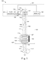
- FIG. 1 illustrates a schematic diagram of an embodiment of a drilling system having drilling fluid parameter monitoring function in accordance with the present disclosure
- FIG. 2 illustrates a schematic diagram of an embodiment of a reader module mounted on the drilling system as shown in FIG. 1 ;
- FIG. 3 illustrates a schematic diagram of another embodiment of a reader module mounted on the drilling system as shown in FIG. 1 ;
- FIG. 4 illustrates a sectional schematic diagram of a drilling assembly in the drilling system along I-I as shown in FIG. 2 or FIG. 3 ;
- FIG. 5 illustrates a schematic diagram of an embodiment of a reader and an RF tag on the drilling system as shown in FIG. 1 ;
- FIG. 6 illustrates a graph of flow velocity of a drilling fluid generated by the drilling system as shown in FIG. 1 ;
- FIG. 7 illustrates another sectional schematic diagram of a drilling assembly along I-I in the drilling system as shown in FIG. 2 or FIG. 3 ;
- FIG. 8 illustrates another sectional schematic diagram of a drilling assembly along I-I in the drilling system as shown in FIG. 2 or FIG. 3 ;
- FIG. 9 illustrates a schematic diagram of an embodiment of flow velocities at different position points of the sectional fluid as shown in FIG. 8 ;
- FIG. 10 illustrates a flow chart of an embodiment of a method for monitoring a drilling fluid parameter of the present disclosure.
- FIG. 1 which illustrates an embodiment of a drilling system 100 provided by the present invention and having drilling fluid parameter monitoring function.
- the drilling system 100 may be used to drill a wellbore 121 to access a hydrocarbon reservoir.
- the wellbore 121 is an onshore wellbore.
- wellbore 121 is an offshore wellbore.
- the drilling system 100 provided by the present invention may be utilized to access an offshore hydrocarbon reservoir.
- the drilling system 100 comprises a drilling platform 101 and a drilling assembly 103 .
- drilling platform 101 is deployed on a drilling vessel.
- drilling platform 101 is supported by an offshore truss.
- Drilling platform 101 may control the drilling assembly 103 as it penetrates formation 107 and creates wellbore 121 .
- drilling platform 101 includes fluid reservoir 131 , fluid pump 135 , rotary driving device 137 , controller 138 and other components not shown on the drilling platform 101 .
- Drilling assembly 103 is connected to the bottom of the drilling platform 101 .
- drilling assembly 103 comprises a drill string 110 , drill head 114 , riser 111 , lower marine riser package (LMRP) 113 and blowout preventer (BOP) 115 .
- LMRP lower marine riser package
- BOP blowout preventer
- rotary driving device 137 Under the control of controller 138 , causes drill head 114 to rotate, penetrate formation 107 creating wellbore 121 thereby. Meanwhile, by action of one or more fluid pumps 135 , drilling fluid 141 , at times herein referred to as drilling mud, move from fluid reservoir 131 and is injected into drill string 110 via injection pipe 132 wherein it flows and reaches drill head 114 . Thereafter, a returned drilling fluid 143 is returns toward the drilling platform 101 via the blowout prevent 115 , lower marine riser, 113 and annular space 122 . Returned drilling fluid may be directed, for example, to a portion of fluid reservoir 131 via return pipe 133 . Annular space 122 is defined by the outer surface of drill string 110 and an inner surface of riser 111 .
- the drilling fluid 141 maintains a sufficient hydrostatic pressure to balance a pressure of a fluid from the formation entering the well bore, at times herein referred to as a formation fluid.
- the drilling fluid also acts to cool drill head 114 , and entrains a mixture of solid materials created by the action of the drill on the formation during the creation of drilling of the wellbore.
- the drilling fluid 141 may include water, oil and/or other drilling fluid ingredients.
- Returned drilling fluid, 143 may include solids formed during drilling of the wellbore.
- the returned drilling fluid 143 may be treated on the drilling platform 101 , for example, by filtering the returned drilling fluid 143 to remove the substances such as formation solids contained therein.
- the treated returned drilling fluid 143 can be recycled and reused as drilling fluid 141 .
- a pressure of a fluid 117 entering into the wellbore from the formation may be greater than a pressure exerted by the drilling fluid above, and results in a kick.
- the returned drilling fluid 143 may be driven by fluid 117 through annular space 122 and erupt from the drilling assembly 103 upon arriving at the drilling platform 101 in a blowout event.
- an LMRP 113 is disposed at an end of the riser 111 and is adjacent to the blowout preventer 115 .
- the LMRP 113 comprises a connector 127 which joins the LMRP 113 to the riser 111 .
- the LMRP 113 allows the drilling platform 101 to be separated from the wellhead 105 by disconnecting the connector 127 .
- the blowout preventer 115 is disposed between the LMRP 113 and the wellhead 105 .
- the blowout preventer 115 comprises one or more shutoff valves 125 , which are stacked together to seal, partially or completely, the wellhead 105 when a kick occurs.
- the present disclosure further utilizes RFID technology.
- the RFID technology is implemented by mixing RF tags 151 with the drilling fluid 141 , which is in turn injected into the drilling assembly 103 .
- the RF tags may be added into the drilling fluid 141 manually or automatically, and are advantageously dispersed uniformly within drilling fluid 141 .
- RF tags 151 returns toward the drilling platform 101 within returned drilling fluid 143 , data and other information encoded in RF tags 151 is read by reader module 150 and is transmitted to controller 138 via one or more communications links.
- the RF tags may be rapidly read, in a contactless manner, tag data and information encoded in the RF tags notwithstanding the complexity of the returned fluid composition.
- controller 138 disposed on the drilling platform 101 may communicate with the reader module 150 via a communication link.
- the reader module 150 may comprise a plurality of data ports, and the communication link may comprise a plurality of corresponding data communication lines for connecting the data ports of the reader module 150 with the controller 138 .
- the controller 138 is used for receiving the data information from the RF tags and to calculate state parameters of RF tags in the returned drilling fluid.
- the state parameters may include movement speed (e.g., the movement speed along a direction in which the riser 111 extends) of an RF tag and a rotation speed along a cross section (e.g., I-I cross section) of the riser 111 under, for example, the action of a side eddy.
- the state parameters of RF tags in the returned drilling fluid can be used to derive related parameters of the returned drilling fluid.
- the controller may calculate a flow velocity or flow volume of the returned drilling fluid based on the state parameters of RF tags.
- FIG. 2 illustrates an embodiment comprising a multi-reader module 150 mounted on the drilling assembly 103
- FIG. 4 illustrates the drilling assembly 103 along axis I-I as shown in FIG. 2 and FIG. 3
- the reader module 150 comprises 8 (eight) columns of reader units, marked as A to H (See FIG. 4 ), each column including 7 readers, marked as A 1 to A 7 , E 1 to E 7 (See FIG. 2 ).
- the reader module 150 may comprise any number of reader units, and each column of reader units may comprise any number of readers.
- the number and mounting positions of the readers may be reasonably selected according to the cost and the requirement of accuracy for data detection.
- the plurality of readers are arranged uniformly around the blowout preventer 115 .
- the reader module 150 may also be arranged on the riser.
- Reader module 150 comprises a plurality of reader groups, e.g. 150 a and 150 b , and the reader module 150 as shown in FIG. 2 may be used as each one of the reader groups as shown in FIG. 3 .
- Each reader group may be arranged on any suitable portion of the drilling assembly 103 , for example, reader group 150 a is arranged on the blowout preventer 115 , and reader group 150 b is arranged on the riser 111 .
- Each reader group is distributed in equal spacing S or in non-equal spacing along an extending direction of the riser 111 .
- FIG. 5 the figure illustrates an encounter between a reader A 7 and a passive RF tag 1511 .
- RF tag 1511 has no internal power supply.
- Reader A 7 transmits radio wave energy 1513 at a specific frequency to RF tag 1511 via an antenna 1502 .
- Passive RF tag 1511 receives the radio wave energy 1513 via an antenna 1510 and drives an electronic circuit 1514 to send data information stored in a memory chip 1512 in a corresponding tag identification number signal 1515 to the reader A 7 via the antenna 1510 .
- An information receiver 1504 of the reader A 7 receives the tag identification number signal 1505 and transmits the tag identification number data to the controller 138 .
- the data information stored in the memory chip 1512 includes not only a tag identification number (a unique ID for each RF tag), but also other data information (e.g., encryption program) pre-stored in the RF tag 1511 .
- the controller 138 may calculate, based on a time point when each reader receives the tag identification number information 1515 and a position of the corresponding reader, a moving speed of the RF tag 1511 which transmits this unique tag identification number information 1515 in the returned drilling fluid 143 along the extending direction of the riser 111 and a rotation speed of the RF tag 1511 along a cross section (e.g., I-I section) of the riser 111 under an effect of a side eddy.
- the moving speed of the RF tag 151 in the returned drilling fluid 143 can reflect the related parameter information (such as a flow velocity, a flow volume, and the like) of the returned drilling fluid 143 .
- the RF tag 1511 is a semi-active RF tag.
- the semi-active RF tag 1511 comprises a small-sized power supply, which provides sufficient electric power to drive the memory chip 1512 such that the antenna 1510 does not need to receive electromagnetic wave energy from the reader A 7 , and RF tag is capable of transmitting the tag identification number signal 1515 on its own, thereby the data information stored in the memory chip 1512 can be transmitted more rapidly and more efficiently.
- the RF tag 1511 is an active RF tag.
- the active RF tag 1511 may comprises a power source to supply the electric energy needed by the internal memory chip 1512 to generate the external tag identification number signal 1515 .
- the active RF tag 1511 may have a longer data transmission distance capability and a larger data storage capacity (e.g., storing position information of the reader) transmitted from the reader A 7 .
- the readers A 1 ⁇ A 7 are uniformly disposed along the extending direction of the riser 111 .
- each of the readers A 1 ⁇ A 7 receives the tag identification number signal 1515 sent out by the RF tag 1511 and transmits the tag identification number signal 1515 to the controller 138 in turn. Then, the tag identification number signal 1515 is decoded and identified in the controller 138 . Since each RF tag 1511 includes its unique tag identification number, the controller 138 can decode and identify the corresponding RF tag 1511 based on the unique tag identification number information 1515 .
- the horizontal axis represents time (t 1 , t 2 , t 3 . . . t 7 ) when each of the readers A 1 ⁇ A 7 in turn detects the tag identification number signal 1515 sent out by the RF tag 1511
- the longitudinal axis represents a position of each of the readers A 1 ⁇ A 7 on the blowout preventer 115 .
- the distance between every two adjacent readers e.g., reader A 1 and reader A 2
- the controller 138 may implement a least squares method or other mathematical protocol to calculate the moving speed of the RF tag 1511 along the extending direction of the riser 111 in the returned drilling fluid 143 .
- Curve 601 illustrates the resultant curve of velocity.
- the moving speeds of the other RF tags 151 along the extending direction of the riser 111 in the returned drilling fluid 143 can all be calculated in accordance with the same or similar methodology.
- Other reader units such as E 1 ⁇ E 7 may also calculate the moving speed of each RF tag along the extending direction of the riser 111 in the returned drilling fluid 143 analogously.
- the moving speeds along the extending direction of the riser 111 are calculated, respectively, by the reader units such as A 1 ⁇ A 7 , E 1 -E 7 are further averaged to obtain an average moving speed of each RF tag 151 along the extending direction of the riser 111 , thus providing an alternate and at time more realistic expression of RF tag and fluid velocity.
- FIG. 7 the figure illustrates a drilling assembly along axis I-I as shown in FIG. 2 and FIG. 3 .
- each of the readers A 7 ⁇ E 7 can detect the tag identification number information 1515 sent out by the RF tag 1511 .
- a specific position parameter of the RF tag 1511 within the annular space 122 can be calculated based on a time difference on which each of the readers A 7 ⁇ E 7 receives the tag identification number 1515 .
- the specific position parameters of the RF tag at each cross section can be calculated.
- a rotation speed of the RF tag 1511 along the cross section I-I of the riser 111 can be calculated based on different position parameters of the RF tag 1511 in the annular space 122 and time interval parameters on which the different position parameters are detected.
- each of the readers A 7 -E 7 can receive the tag identification number signals 1515 sent out by the other RF tags, so as to calculate the specific position parameters of the other RF tags in the annular space 122 and the rotation speeds of the other RF tags along the cross section I-I of the riser 111 .
- the flow velocity of the returned drilling fluid 143 may be calculated based on the moving speed of the at least one RF tag 151 along the extending direction of the riser 111 and the rotation speed of the at least one RF tag 151 along a cross section (e.g., I-I cross section) of the riser 111 under an effect of a side eddy.
- the flow volume of the returned drilling fluid 143 may be calculated based on the flow velocity of the returned drilling fluid 143 and the cross sectional area of the annular space 122 .
- the moving speed of each of the RF tags 151 is calculated correspondingly at a cross section I-I of the riser 111 . Since the moving speeds of each of the RF tags 151 may be different, the moving speeds of the RF tags 151 at different positions within annular space 122 can be obtained, as shown in FIG. 9 .
- annular space 122 is divided into a plurality of cross sectional units. A flow volume at each cross sectional unit can be obtained by multiplying each cross sectional unit with the moving speed of the RF tag 151 corresponding to this cross sectional unit. Then the flow volume of the returned drilling fluid 143 can be obtained by summing the flow volumes at each of the cross sectional units.
- the related parameters of the returned drilling fluid 143 can provide basis for the subsequent kick prediction. For instance, when the flow velocity of the returned drilling fluid 143 exceeds the flow velocity of the injected drilling fluid 141 , a kick may happen. When the flow volume of the returned drilling fluid 143 is far greater than the flow volume of the drilling fluid 141 , a kick may happen. After a comprehensive analysis for the variety of parameters of the returned drilling fluid 143 , it may predict whether a kick would happen.
- the returned drilling fluid 143 is prevented from being delivered upward to the drilling platform 101 , by partly closing a shutoff valve of the blowout preventer 115 to seal the annular space 122 .
- the wellhead 105 may be completely sealed, by completely closing the shutoff valve of the blowout preventer 115 to completely seal the wellhead 105 , i.e., a channel of the drilling fluid 141 and a channel of the returned drilling fluid 143 are both shut off.
- the use of RFID technology as disclosed herein enables the controller 138 to rapidly receive the data information of the at least one RF tag 151 read by the reader module 150 .
- the controller 138 may identify each RF tag 151 and calculate the moving speed of each RF tag 151 along the extending direction of the riser 111 in the returned drilling fluid 143 and the rotation speed of each RF tag 151 along a cross section (e.g., I-I section) of the riser 111 under the effect of the side eddy.
- the controller 138 may simultaneously monitor a variety of parameters of the returned drilling fluid 143 based on the state parameters of each of the RF tags 151 in the returned drilling fluid 143 so as to provide important basis for kick prediction.
- the method 1000 for monitoring parameters of a returned drilling fluid comprises the following steps:
- Step 1001 a drilling fluid 141 mixed with at least one RF tag 151 is injected into a drilling assembly 103 .
- Step 1003 data information of the at least one RF tag 151 moving with a returned drilling fluid 143 is read by a reader module 150 .
- Step 1005 the data information of the at least one RF tag 151 is received to calculate related parameters of the returned drilling fluid 143 .
Abstract
Description
Claims (21)
Applications Claiming Priority (3)
| Application Number | Priority Date | Filing Date | Title |
|---|---|---|---|
| CN201410264062.3 | 2014-06-13 | ||
| CN201410264062.3A CN105332689B (en) | 2014-06-13 | 2014-06-13 | drilling fluid parameter monitoring system and method |
| PCT/US2015/035520 WO2015191979A1 (en) | 2014-06-13 | 2015-06-12 | System and method for drilling fluid parameters detection |
Publications (2)
| Publication Number | Publication Date |
|---|---|
| US20170107812A1 US20170107812A1 (en) | 2017-04-20 |
| US11118446B2 true US11118446B2 (en) | 2021-09-14 |
Family
ID=53443045
Family Applications (1)
| Application Number | Title | Priority Date | Filing Date |
|---|---|---|---|
| US15/317,223 Active 2035-12-17 US11118446B2 (en) | 2014-06-13 | 2015-06-12 | System and method for drilling fluid parameters detection |
Country Status (6)
| Country | Link |
|---|---|
| US (1) | US11118446B2 (en) |
| KR (1) | KR20170016002A (en) |
| CN (1) | CN105332689B (en) |
| MX (1) | MX2016016375A (en) |
| NO (1) | NO20161932A1 (en) |
| WO (1) | WO2015191979A1 (en) |
Families Citing this family (6)
| Publication number | Priority date | Publication date | Assignee | Title |
|---|---|---|---|---|
| CN107288620B (en) * | 2017-08-24 | 2023-06-06 | 重庆科技学院 | Intelligent detection device for liquid level of oil drilling well head anti-overflow pipe drilling fluid |
| CN113123757A (en) * | 2020-01-16 | 2021-07-16 | 成都维锐泰达能源技术有限公司 | Intelligent delivery device |
| CN111396031A (en) * | 2020-03-18 | 2020-07-10 | 青海省环境地质勘查局 | Drilling fluid parameter monitoring system and method |
| CN111456659A (en) * | 2020-04-30 | 2020-07-28 | 中国石油天然气集团有限公司 | Monitoring method for monitoring overflow leakage in drilling process |
| US11773715B2 (en) * | 2020-09-03 | 2023-10-03 | Saudi Arabian Oil Company | Injecting multiple tracer tag fluids into a wellbore |
| CN116067421A (en) * | 2022-11-18 | 2023-05-05 | 中国石油天然气集团有限公司 | Measuring device and measuring method for multi-point multifunctional detection of drilling fluid |
Citations (19)
| Publication number | Priority date | Publication date | Assignee | Title |
|---|---|---|---|---|
| EP0848512A2 (en) | 1996-12-11 | 1998-06-17 | Labarge, Inc. | Method of and system for communication between points along a fluid flow |
| US7180288B2 (en) | 2004-11-10 | 2007-02-20 | Schlumberger Technology Corporation | Downhole NMR flow and formation characterization while sampling fluids |
| WO2007052864A1 (en) | 2005-11-04 | 2007-05-10 | Korea Water Resources Corporation | A system for measuring flow velocity using real time locating system and a measuring float used in the said system |
| US7334651B2 (en) | 2004-07-21 | 2008-02-26 | Schlumberger Technology Corporation | Kick warning system using high frequency fluid mode in a borehole |
| WO2008028746A1 (en) | 2006-09-04 | 2008-03-13 | Sulzer Pumpen Ag | Method of and system for monitoring flow velocity |
| CN201152171Y (en) | 2008-01-18 | 2008-11-19 | 邹野 | Drilling mud integral parameter measuring equipment |
| US20080316049A1 (en) * | 2007-06-25 | 2008-12-25 | Turbo-Chem International, Inc. | RFID Tag Tracer Method and Apparatus |
| EP2024763A1 (en) | 2006-05-17 | 2009-02-18 | Sclumberger Technology B.V. | Methods and systems for evaluation of hydrocarbon reservoirs and associated fluids using biological tags and real-time pcr |
| US20090266544A1 (en) | 2006-08-21 | 2009-10-29 | Redlinger Thomas M | Signal operated tools for milling, drilling, and/or fishing operations |
| US20100044034A1 (en) * | 2007-12-13 | 2010-02-25 | Louise Bailey | Subsurface tagging system with wired tubulars |
| US20100139386A1 (en) * | 2008-12-04 | 2010-06-10 | Baker Hughes Incorporated | System and method for monitoring volume and fluid flow of a wellbore |
| US20100193184A1 (en) * | 2007-12-13 | 2010-08-05 | Lee Dolman | System and method of monitoring flow in a wellbore |
| WO2011017278A1 (en) | 2009-08-02 | 2011-02-10 | Cameron International Corporation | Arc rfid antenna |
| US8016036B2 (en) | 2007-11-14 | 2011-09-13 | Baker Hughes Incorporated | Tagging a formation for use in wellbore related operations |
| CN102289638A (en) | 2010-05-25 | 2011-12-21 | 韦特柯格雷控制系统有限公司 | Obtaining data from an underwater component |
| US20120075113A1 (en) | 2010-07-22 | 2012-03-29 | Hm Energy Llc | Method and apparatus for automatic down-hole asset monitoring |
| US20120132418A1 (en) * | 2010-11-22 | 2012-05-31 | Mcclung Iii Guy L | Wellbore operations, systems, and methods with McNano devices |
| US20130319767A1 (en) | 2011-01-21 | 2013-12-05 | Weatherford/Lamb, Inc. | Telemetry operated circulation sub |
| US10047604B2 (en) * | 2013-08-28 | 2018-08-14 | Halliburton Energy Services, Inc. | System for tracking and sampling wellbore cuttings using RFID tags |
-
2014
- 2014-06-13 CN CN201410264062.3A patent/CN105332689B/en not_active Expired - Fee Related
-
2015
- 2015-06-12 MX MX2016016375A patent/MX2016016375A/en unknown
- 2015-06-12 WO PCT/US2015/035520 patent/WO2015191979A1/en active Application Filing
- 2015-06-12 KR KR1020177000897A patent/KR20170016002A/en not_active Application Discontinuation
- 2015-06-12 US US15/317,223 patent/US11118446B2/en active Active
-
2016
- 2016-12-05 NO NO20161932A patent/NO20161932A1/en not_active Application Discontinuation
Patent Citations (19)
| Publication number | Priority date | Publication date | Assignee | Title |
|---|---|---|---|---|
| EP0848512A2 (en) | 1996-12-11 | 1998-06-17 | Labarge, Inc. | Method of and system for communication between points along a fluid flow |
| US7334651B2 (en) | 2004-07-21 | 2008-02-26 | Schlumberger Technology Corporation | Kick warning system using high frequency fluid mode in a borehole |
| US7180288B2 (en) | 2004-11-10 | 2007-02-20 | Schlumberger Technology Corporation | Downhole NMR flow and formation characterization while sampling fluids |
| WO2007052864A1 (en) | 2005-11-04 | 2007-05-10 | Korea Water Resources Corporation | A system for measuring flow velocity using real time locating system and a measuring float used in the said system |
| EP2024763A1 (en) | 2006-05-17 | 2009-02-18 | Sclumberger Technology B.V. | Methods and systems for evaluation of hydrocarbon reservoirs and associated fluids using biological tags and real-time pcr |
| US20090266544A1 (en) | 2006-08-21 | 2009-10-29 | Redlinger Thomas M | Signal operated tools for milling, drilling, and/or fishing operations |
| WO2008028746A1 (en) | 2006-09-04 | 2008-03-13 | Sulzer Pumpen Ag | Method of and system for monitoring flow velocity |
| US20080316049A1 (en) * | 2007-06-25 | 2008-12-25 | Turbo-Chem International, Inc. | RFID Tag Tracer Method and Apparatus |
| US8016036B2 (en) | 2007-11-14 | 2011-09-13 | Baker Hughes Incorporated | Tagging a formation for use in wellbore related operations |
| US20100044034A1 (en) * | 2007-12-13 | 2010-02-25 | Louise Bailey | Subsurface tagging system with wired tubulars |
| US20100193184A1 (en) * | 2007-12-13 | 2010-08-05 | Lee Dolman | System and method of monitoring flow in a wellbore |
| CN201152171Y (en) | 2008-01-18 | 2008-11-19 | 邹野 | Drilling mud integral parameter measuring equipment |
| US20100139386A1 (en) * | 2008-12-04 | 2010-06-10 | Baker Hughes Incorporated | System and method for monitoring volume and fluid flow of a wellbore |
| WO2011017278A1 (en) | 2009-08-02 | 2011-02-10 | Cameron International Corporation | Arc rfid antenna |
| CN102289638A (en) | 2010-05-25 | 2011-12-21 | 韦特柯格雷控制系统有限公司 | Obtaining data from an underwater component |
| US20120075113A1 (en) | 2010-07-22 | 2012-03-29 | Hm Energy Llc | Method and apparatus for automatic down-hole asset monitoring |
| US20120132418A1 (en) * | 2010-11-22 | 2012-05-31 | Mcclung Iii Guy L | Wellbore operations, systems, and methods with McNano devices |
| US20130319767A1 (en) | 2011-01-21 | 2013-12-05 | Weatherford/Lamb, Inc. | Telemetry operated circulation sub |
| US10047604B2 (en) * | 2013-08-28 | 2018-08-14 | Halliburton Energy Services, Inc. | System for tracking and sampling wellbore cuttings using RFID tags |
Non-Patent Citations (4)
| Title |
|---|
| A PCT Search Report and Written Opinion issued in connection with corresponding PCT Application No. PCT/US2015/035520 dated Nov. 4, 2015. |
| Cayeux et al., "Advanced Drilling Simulation Environment for Testing New Drilling Automation Techniques and Practices", Society of Petroleum Engineers, OnePetro, vol. No. 27, Issue No. 4, pp. 559-573, Dec. 2012 |
| First Office Action and Search issued in connection with corresponding CN Application No. 201410264062.3 dated Sep. 26, 2017. |
| Hargreaves et al., "Early Kick Detection for Deepwater Drilling: New Probabilistic Methods Applied in the Field", Society of Petroleum Engineers, OnePetro, pp. 1-11, Sep. 30-Oct. 3, 2001. |
Also Published As
| Publication number | Publication date |
|---|---|
| CN105332689B (en) | 2018-10-12 |
| US20170107812A1 (en) | 2017-04-20 |
| NO20161932A1 (en) | 2016-12-05 |
| MX2016016375A (en) | 2017-05-01 |
| KR20170016002A (en) | 2017-02-10 |
| WO2015191979A1 (en) | 2015-12-17 |
| CN105332689A (en) | 2016-02-17 |
Similar Documents
| Publication | Publication Date | Title |
|---|---|---|
| US11118446B2 (en) | System and method for drilling fluid parameters detection | |
| US20200190959A1 (en) | Monitoring rig activities | |
| CA2988463C (en) | Wellsite equipment health monitoring | |
| US10087745B2 (en) | Bore object characterization system for well assemblies | |
| US10047604B2 (en) | System for tracking and sampling wellbore cuttings using RFID tags | |
| CA3034293A1 (en) | Fluid production network leak detection | |
| US8767063B1 (en) | System for monitoring a marine well for shallow-water flow | |
| MX2014008800A (en) | Systems, methods and devices for analyzing drilling fluid. | |
| CN103926422A (en) | Fluid measuring system and method | |
| US10151159B2 (en) | Kick detection systems and methods | |
| US20170089163A1 (en) | Methods and systems for monitoring a blowout preventor | |
| CA2900935A1 (en) | Diverting flow in a drilling fluid circulation system to regulate drilling fluid pressure | |
| NO20190391A1 (en) | Riser joint system, well drilling system and method for well drilling system | |
| NO20180769A1 (en) | Kick detection system and method for drilling well and associated well drilling system | |
| CN204571978U (en) | A kind of underground communication system for Underwell anti-injection | |
| US20160245076A1 (en) | Downhole Measurement While Drilling Tool with a Spectrometer and Method of Operating Same | |
| Feng | Advances in Oil and Gas Well Engineering | |
| Temizel et al. | A Comprehensive Review of the Fourth Industrial Revolution IR 4.0 in Oil and Gas Industry | |
| US11899438B1 (en) | Distributed control system with failover capabilities for physical well equipment | |
| Moss | A comparison of Active and Passive Magnetic Ranging Techniques in a Relief Well Application | |
| WO2023070050A1 (en) | Drilling fluid dilution system |
Legal Events
| Date | Code | Title | Description |
|---|---|---|---|
| AS | Assignment |
Owner name: GENERAL ELECTRIC COMPANY, NEW YORK Free format text: ASSIGNMENT OF ASSIGNORS INTEREST;ASSIGNORS:SHANG, WEIHUA;CHENG, GANG;NIU, RAN;AND OTHERS;SIGNING DATES FROM 20140808 TO 20140916;REEL/FRAME:040599/0828 |
|
| STPP | Information on status: patent application and granting procedure in general |
Free format text: RESPONSE TO NON-FINAL OFFICE ACTION ENTERED AND FORWARDED TO EXAMINER |
|
| STPP | Information on status: patent application and granting procedure in general |
Free format text: FINAL REJECTION MAILED |
|
| AS | Assignment |
Owner name: BAKER HUGHES OILFIELD OPERATIONS LLC, TEXAS Free format text: ASSIGNMENT OF ASSIGNORS INTEREST;ASSIGNOR:GENERAL ELECTRIC COMPANY;REEL/FRAME:049755/0352 Effective date: 20170703 |
|
| STCB | Information on status: application discontinuation |
Free format text: ABANDONED -- FAILURE TO RESPOND TO AN OFFICE ACTION |
|
| STCC | Information on status: application revival |
Free format text: WITHDRAWN ABANDONMENT, AWAITING EXAMINER ACTION |
|
| STPP | Information on status: patent application and granting procedure in general |
Free format text: DOCKETED NEW CASE - READY FOR EXAMINATION |
|
| STPP | Information on status: patent application and granting procedure in general |
Free format text: NOTICE OF ALLOWANCE MAILED -- APPLICATION RECEIVED IN OFFICE OF PUBLICATIONS |
|
| STPP | Information on status: patent application and granting procedure in general |
Free format text: PUBLICATIONS -- ISSUE FEE PAYMENT VERIFIED |
|
| STCF | Information on status: patent grant |
Free format text: PATENTED CASE |
|
| AS | Assignment |
Owner name: HYDRIL USA DISTRIBUTION LLC, TEXAS Free format text: ASSIGNMENT OF ASSIGNORS INTEREST;ASSIGNOR:BAKER HUGHES OILFIELD OPERATIONS, LLC;REEL/FRAME:057608/0034 Effective date: 20210902 |