US11115976B2 - Method for transmitting/receiving uplink control channel in frame structure of short transmission time interval and device therefor - Google Patents
Method for transmitting/receiving uplink control channel in frame structure of short transmission time interval and device therefor Download PDFInfo
- Publication number
- US11115976B2 US11115976B2 US16/331,969 US201716331969A US11115976B2 US 11115976 B2 US11115976 B2 US 11115976B2 US 201716331969 A US201716331969 A US 201716331969A US 11115976 B2 US11115976 B2 US 11115976B2
- Authority
- US
- United States
- Prior art keywords
- spucch
- transmitting
- downlink data
- data channel
- spdsch
- Prior art date
- Legal status (The legal status is an assumption and is not a legal conclusion. Google has not performed a legal analysis and makes no representation as to the accuracy of the status listed.)
- Active
Links
- 238000000034 method Methods 0.000 title claims abstract description 54
- 230000005540 biological transmission Effects 0.000 title description 83
- 230000011664 signaling Effects 0.000 claims abstract description 40
- 101000741965 Homo sapiens Inactive tyrosine-protein kinase PRAG1 Proteins 0.000 claims 2
- 102100038659 Inactive tyrosine-protein kinase PRAG1 Human genes 0.000 claims 2
- 101100465000 Mus musculus Prag1 gene Proteins 0.000 abstract description 35
- 230000004044 response Effects 0.000 abstract description 11
- 208000037918 transfusion-transmitted disease Diseases 0.000 description 47
- 238000013468 resource allocation Methods 0.000 description 21
- 238000004891 communication Methods 0.000 description 17
- 238000012545 processing Methods 0.000 description 14
- 238000010586 diagram Methods 0.000 description 11
- 230000009467 reduction Effects 0.000 description 9
- 101150069124 RAN1 gene Proteins 0.000 description 6
- 101100355633 Salmo salar ran gene Proteins 0.000 description 6
- 125000004122 cyclic group Chemical group 0.000 description 6
- 238000013507 mapping Methods 0.000 description 6
- 238000013461 design Methods 0.000 description 3
- 230000000694 effects Effects 0.000 description 3
- 238000012986 modification Methods 0.000 description 3
- 230000004048 modification Effects 0.000 description 3
- 230000001360 synchronised effect Effects 0.000 description 3
- 101100264657 Enterobacteria phage T4 y12D gene Proteins 0.000 description 2
- 101150014328 RAN2 gene Proteins 0.000 description 2
- 230000001934 delay Effects 0.000 description 2
- 238000005516 engineering process Methods 0.000 description 2
- 238000010295 mobile communication Methods 0.000 description 2
- 230000007480 spreading Effects 0.000 description 2
- 101100411667 Arabidopsis thaliana RAN4 gene Proteins 0.000 description 1
- 108010003272 Hyaluronate lyase Proteins 0.000 description 1
- 238000007792 addition Methods 0.000 description 1
- 238000013459 approach Methods 0.000 description 1
- 239000000969 carrier Substances 0.000 description 1
- 230000023402 cell communication Effects 0.000 description 1
- 230000008859 change Effects 0.000 description 1
- 239000013256 coordination polymer Substances 0.000 description 1
- 238000010348 incorporation Methods 0.000 description 1
- 230000007774 longterm Effects 0.000 description 1
- 230000007246 mechanism Effects 0.000 description 1
- 230000003287 optical effect Effects 0.000 description 1
- 239000013307 optical fiber Substances 0.000 description 1
- 230000008569 process Effects 0.000 description 1
- 230000008054 signal transmission Effects 0.000 description 1
- 238000006467 substitution reaction Methods 0.000 description 1
- 238000012546 transfer Methods 0.000 description 1
- 238000012795 verification Methods 0.000 description 1
Images


Classifications
-
- H—ELECTRICITY
- H04—ELECTRIC COMMUNICATION TECHNIQUE
- H04L—TRANSMISSION OF DIGITAL INFORMATION, e.g. TELEGRAPHIC COMMUNICATION
- H04L5/00—Arrangements affording multiple use of the transmission path
- H04L5/003—Arrangements for allocating sub-channels of the transmission path
- H04L5/0053—Allocation of signaling, i.e. of overhead other than pilot signals
-
- H—ELECTRICITY
- H04—ELECTRIC COMMUNICATION TECHNIQUE
- H04W—WIRELESS COMMUNICATION NETWORKS
- H04W72/00—Local resource management
- H04W72/04—Wireless resource allocation
- H04W72/044—Wireless resource allocation based on the type of the allocated resource
- H04W72/0446—Resources in time domain, e.g. slots or frames
-
- H—ELECTRICITY
- H04—ELECTRIC COMMUNICATION TECHNIQUE
- H04L—TRANSMISSION OF DIGITAL INFORMATION, e.g. TELEGRAPHIC COMMUNICATION
- H04L1/00—Arrangements for detecting or preventing errors in the information received
- H04L1/12—Arrangements for detecting or preventing errors in the information received by using return channel
- H04L1/16—Arrangements for detecting or preventing errors in the information received by using return channel in which the return channel carries supervisory signals, e.g. repetition request signals
- H04L1/18—Automatic repetition systems, e.g. Van Duuren systems
- H04L1/1812—Hybrid protocols; Hybrid automatic repeat request [HARQ]
-
- H—ELECTRICITY
- H04—ELECTRIC COMMUNICATION TECHNIQUE
- H04L—TRANSMISSION OF DIGITAL INFORMATION, e.g. TELEGRAPHIC COMMUNICATION
- H04L1/00—Arrangements for detecting or preventing errors in the information received
- H04L1/12—Arrangements for detecting or preventing errors in the information received by using return channel
- H04L1/16—Arrangements for detecting or preventing errors in the information received by using return channel in which the return channel carries supervisory signals, e.g. repetition request signals
- H04L1/18—Automatic repetition systems, e.g. Van Duuren systems
- H04L1/1829—Arrangements specially adapted for the receiver end
- H04L1/1861—Physical mapping arrangements
-
- H—ELECTRICITY
- H04—ELECTRIC COMMUNICATION TECHNIQUE
- H04L—TRANSMISSION OF DIGITAL INFORMATION, e.g. TELEGRAPHIC COMMUNICATION
- H04L5/00—Arrangements affording multiple use of the transmission path
- H04L5/003—Arrangements for allocating sub-channels of the transmission path
- H04L5/0053—Allocation of signaling, i.e. of overhead other than pilot signals
- H04L5/0055—Physical resource allocation for ACK/NACK
-
- H—ELECTRICITY
- H04—ELECTRIC COMMUNICATION TECHNIQUE
- H04L—TRANSMISSION OF DIGITAL INFORMATION, e.g. TELEGRAPHIC COMMUNICATION
- H04L5/00—Arrangements affording multiple use of the transmission path
- H04L5/0091—Signaling for the administration of the divided path
- H04L5/0094—Indication of how sub-channels of the path are allocated
-
- H04W72/0413—
-
- H04W72/042—
-
- H—ELECTRICITY
- H04—ELECTRIC COMMUNICATION TECHNIQUE
- H04W—WIRELESS COMMUNICATION NETWORKS
- H04W72/00—Local resource management
- H04W72/20—Control channels or signalling for resource management
- H04W72/21—Control channels or signalling for resource management in the uplink direction of a wireless link, i.e. towards the network
-
- H—ELECTRICITY
- H04—ELECTRIC COMMUNICATION TECHNIQUE
- H04W—WIRELESS COMMUNICATION NETWORKS
- H04W72/00—Local resource management
- H04W72/20—Control channels or signalling for resource management
- H04W72/23—Control channels or signalling for resource management in the downlink direction of a wireless link, i.e. towards a terminal
-
- H—ELECTRICITY
- H04—ELECTRIC COMMUNICATION TECHNIQUE
- H04W—WIRELESS COMMUNICATION NETWORKS
- H04W76/00—Connection management
- H04W76/20—Manipulation of established connections
- H04W76/27—Transitions between radio resource control [RRC] states
-
- H—ELECTRICITY
- H04—ELECTRIC COMMUNICATION TECHNIQUE
- H04L—TRANSMISSION OF DIGITAL INFORMATION, e.g. TELEGRAPHIC COMMUNICATION
- H04L5/00—Arrangements affording multiple use of the transmission path
- H04L5/003—Arrangements for allocating sub-channels of the transmission path
- H04L5/0037—Inter-user or inter-terminal allocation
Definitions
- the present disclosure relates to a method of transmitting and receiving an uplink control channel based on a short transmission time interval frame structure in the 3rd generation partnership project (3GPP) long term evolution (LTE)/LTE-A system.
- 3GPP 3rd generation partnership project
- LTE long term evolution
- short TTI a frame having a short Transmission Time Interval (hereinafter referred to as “short TTI” or “sTTI”) and operation thereof have been standardized.
- Such an sTTI frame structure has the typical LTE/LTE-Advanced frame structure.
- the sTTI frame may be configured with 2, 4, or 7 symbols, and an uplink frame structure may be configured with different from a downlink frame structure. Since the uplink frame structure is different from the downlink frame structure, there is a conflict problem when an uplink control channel is transmitted for a downlink data channel.
- An aspect of the present disclosure is to provide a method of transmitting an uplink control channel in a short transmission time interval frame structure.
- the method may include receiving a downlink data channel through a short transmission time interval frame from a base station, receiving an offset value set for each user equipment through higher layer signaling in order to transmit the uplink control channel in response to the downlink data channel, and transmitting the uplink control channel through a resource determined based on the offset value.
- Another aspect of the present disclosure is to provide a method of receiving an uplink control channel in a short transmission time interval frame structure.
- the method may include transmitting a downlink data channel through a short transmission time interval frame to a user equipment, transmitting an offset value set for each user equipment through higher layer signaling in order to transmit the uplink control channel in response to the downlink data channel, and receiving the uplink control channel through a resource determined based on the offset value.
- the user equipment may include a receiver configured to receive a downlink data channel through a short transmission time interval frame from a base station, receive an offset value set for each user equipment through higher layer signaling in order to transmit the uplink control channel in response to the downlink data channel, and a controller configured to transmit the uplink control channel through a resource determined based on the offset value.
- the base station may include a controller configured to transmit a downlink data channel through a short transmission time interval frame to a user equipment, transmit an offset value set for each user equipment through higher layer signaling in order to transmit the uplink control channel in response to the downlink data channel, and a receiver configured to receive the uplink control channel through a resource determined based on the offset value.
- a method of configuring an uplink control channel resource for a downlink data channel in a short transmission time interval frame structure is provided.
- the uplink control channel can be transmitted without overlapping of resources for uplink control channel transmission.
- FIG. 1 is a diagram illustrating eNB and UE processing delays and HARQ RTT.
- FIG. 2 is a diagram illustrating resource mapping per PRB in one subframe.
- FIG. 3 is a diagram illustrating PHICH processing of a normal CP case in LTE/LTE-Advanced.
- FIG. 4 is a diagram illustrating a legacy PUCCH uplink structure.
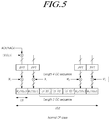
- FIG. 5 is a conceptual diagram illustrating a legacy PUCCH configuration.
- FIG. 6 is a diagram illustrating establishing a linkage between an sPDSCH and an sPUCCH based on an sTTI frame structure of the same symbol length.
- FIG. 7 is a diagram illustrating establishing a linkage between an sPDSCH and an sPUCCH based on sTTI frame structures to which symbol lengths different from each other are applied.
- FIG. 8 is a flowchart illustrating a method of transmitting an sPUCCH in an sTTI frame structure according to at least one embodiment of the present disclosure.
- FIG. 9 is a flowchart illustrating a method of receiving an sPUCCH in an sTTI frame structure according to at least one embodiment of the present disclosure.
- FIG. 10 is a block diagram illustrating a base station according to at least one embodiment of the present disclosure.
- FIG. 11 is a block diagram illustrating a user equipment according to at least one embodiment of the present disclosure.
- a machine type communication (MTC) device in the present specification may refer to a device supporting low cost (or low complexity), a device supporting coverage enhancement, or the like.
- the MTC device in the present specification may refer to a device that supports low cost (or low complexity) and coverage enhancement, or the like.
- the MTC device in the present specification may refer to a device defined in a predetermined category for supporting low cost (or low complexity) and/or coverage enhancement.
- the MTC device in the present specification may refer to a low cost (or low complexity) user equipment (UE) category/type newly defined in 3GPP Release-13 and performing LTE-based MTC-related operations.
- the MTC device in the present specification may refer to a UE category/type defined in or before 3GPP Release-12, which supports enhanced coverage in comparison with the typical LTE coverage or supports low power consumption, or may refer to a low. cost (or low complexity) UE category/type newly defined in Release-13.
- a wireless communication system of the present disclosure is widely installed to provide various communication services, such as a voice communication service, a packet data service, etc.
- the wireless communication system includes a user equipment (UE) and a base station (BS, or eNB).
- the UE in the present specification is defined as a generic term including terminals used in wireless communication.
- the UE includes UEs in wideband code division multiple access (WCDMA), LTE, high speed packet access (HSPA), and the like, a mobile station (MS) in global systems for mobile communication (GSM), a user terminal (UT), a subscriber station (SS), a wireless device, or the like.
- WCDMA wideband code division multiple access
- HSPA high speed packet access
- MS mobile station
- GSM global systems for mobile communication
- UT user terminal
- SS subscriber station
- wireless device or the like.
- a BS or a cell generally refers to a station communicating with the UE.
- the BS or the cell may be referred to as a Node-B, an evolved Node-B (eNB), a sector, a site, a base transceiver system (BTS), an access point, a relay node, a remote radio head (RRH), a radio unit (RU), a small cell, or the like.
- eNB evolved Node-B
- BTS base transceiver system
- RRH remote radio head
- RU radio unit
- the BS or the cell in the present specification is defined as a generic term including some areas or functions covered by a base station controller (BSC) in CDMA, a Node-B in the WCDMA, an evolved Node-B (eNB) or a sector (site) in the LTE, and the like, all of various coverage areas, such as a megacell, a macrocell, a microcell, a picocell, a femtocell and a relay node, RRH, RU, a small cell communication range, or the like.
- BSC base station controller
- eNB evolved Node-B
- site in the LTE
- all of various coverage areas such as a megacell, a macrocell, a microcell, a picocell, a femtocell and a relay node, RRH, RU, a small cell communication range, or the like.
- the BS may be classified into two categories.
- the BS may be referred to i) an apparatus that provides a megacell, a macrocell, a microcell, a picocell, a femtocell, or a small cell, in association with a radio area, or ii) the radio area itself.
- the BS may be referred to all apparatuses providing any radio area, which are controlled by the same entity, or which interact to configure the radio area in cooperation with one another.
- an example of the BS may be an eNB, a RRH, an antenna, a RU, a low power node (LPN), a point, a transmission/reception point, a transmission point, a reception point, or the like.
- the BS may be a radio area itself for receiving or transmitting a signal from UE perspective or neighboring BS perspective.
- the megacell, the macrocell, the microcell, the picocell, the femtocell, or the small cell, the RRH, the antenna, the RU, the LPN, the point, the eNB, the transmission/reception point, the transmission point, or the reception point are collectively referred to as the BS.
- the UE and the BS in the present specification are two entities for performing transmission/reception used to embody the technology and technical spirit described in the present specification.
- the UE and the BS are defined as a generic term and not limited to specific terms or words.
- the UE and the BS are two entities for performing transmission/reception through uplink or downlink used to embody the technology and technical spirit described in the present disclosure.
- the UE and the BS are defined as a generic term and not limited to specific terms or words.
- the uplink (UL) refers to a scheme transmitting/receiving data by a UE to/from a BS
- the downlink (DL) refers to a scheme transmitting/receiving data by a BS to/from a UE.
- any of multiple access techniques may be applied to the wireless communication system.
- the wireless communication system may employ various multiple access techniques, such as code division multiple access (CDMA), time division multiple access (TDMA), frequency division multiple access (FDMA), orthogonal frequency division multiple access (OFDMA), OFDM-TDMA, OFDM-FDMA, OFDM-CDMA, or the like.
- CDMA code division multiple access
- TDMA time division multiple access
- FDMA frequency division multiple access
- OFDMA orthogonal frequency division multiple access
- OFDM-TDMA OFDM-TDMA
- OFDM-FDMA OFDM-FDMA
- OFDM-CDMA OFDM-CDMA
- At least one embodiment of the present disclosure may be applied to resource allocation in as well as asynchronous wireless communication evolving into LTE/LTE-advanced and IMT-2020 beyond GSM, WCDMA, and HSPA, synchronous wireless communication evolving into CDMA, CDMA-2000, and UMB.
- the present disclosure is not limited to or shall not be construed to be limited
- UL transmission and DL transmission may be performed based on i) a time division duplex (TDD) technique performing transmission through different time slots or ii) a frequency division duplex (FDD) technique performing transmission through different frequencies.
- TDD time division duplex
- FDD frequency division duplex
- a standard defines that the UL and the DL is configured based on a single carrier or a pair of carriers.
- the UL and the DL may be established by one or more control channels, such as a physical DL control channel (PDCCH), a physical control format indicator channel (PCFICH), a physical hybrid ARQ indicator channel (PITCH), a physical UP control channel (PUCCH), an enhanced physical DL control channel (EPDCCH), or the like, through which control information is transmitted, and may be established by one or more data channels, such as a physical DL shared channel (PDSCH), a physical UL shared channel (PUSCH), or the like, through which data are transmitted.
- control channels such as a physical DL control channel (PDCCH), a physical control format indicator channel (PCFICH), a physical hybrid ARQ indicator channel (PITCH), a physical UP control channel (PUCCH), an enhanced physical DL control channel (EPDCCH), or the like, through which control information is transmitted
- data channels such as a physical DL
- control information may be transmitted through an enhanced PDCCH (EPDCCH) or extended PDCCH (EPDCCH).
- EPDCCH enhanced PDCCH
- EPDCCH extended PDCCH
- the cell in the present specification may refer to a coverage of a signal transmitted from a transmission point or a transmission/reception point, a component carrier having the coverage of the signal transmitted from the transmission point or the transmission/reception point, or the transmission/reception point itself.
- a wireless communication system to which some embodiments are applied may be i) a coordinated multi-point transmission/reception system (CoMP system) in which two or more transmission/reception points cooperate to transmit a signal, ii) a coordinated multi-antenna transmission system, or iii) a coordinated multi-cell communication system.
- the CoMP system may include at least two multiple transmission/reception points and UEs.
- the multiple transmission/reception points may be at least one RRH that is connected to a BS or macrocell (hereinafter, referred to as ‘eNB’) through an optical cable or an optical fiber and thereby controlled in a wired manner, and that has high transmission power or low transmission power in a macrocell area.
- eNB macrocell
- the DL denotes communication or a communication path from multiple transmission/reception points to a UE.
- the UL denotes communication or a communication path from the UE to the multiple transmission/reception points.
- a transmitter may be a part of multiple transmission/reception points, and a receiver may be a part of the UE.
- a transmitter may be a part of the UE and a receiver may be a part of multiple transmission/reception points.
- signal transmission or reception through PUCCH, PUSCH, PDCCH, EPDCCH, or PDSCH may be referred to as transmission and reception of PUCCH, PUSCH, PDCCH, EPDCCH or PDSCH.
- a description of transmitting or receiving a PDCCH or a description of transmitting or receiving a signal through the PDCCH may include i) meaning of transmitting or receiving an EPDCCH or ii) meaning of transmitting or receiving a signal through the EPDCCH.
- a physical DL control channel described below may denote a PDCCH or an EPDCCH, or the physical DL control channel is also used as meaning including both the PDCCH and the EPDCCH.
- an EPDCCH may be applied to an embodiment described with the PDCCH, as an embodiment of the present disclosure, and the PDCCH may be also applied to an embodiment described with the EPDCCH.
- RRC radio resource control
- the eNB performs DL transmission to UEs.
- the eNB may transmit a physical DL shared channel (PDSCH) which is a primary physical channel for unicast transmission.
- the eNB may also transmit a physical DL control channel (PDCCH) for transmitting i) DL control information such as scheduling required to receive the PDSCH and ii) scheduling approval information for transmission through an UL data channel (for example, a physical UL shared channel (PUSCH)).
- PDSCH physical DL shared channel
- PUSCH physical UL shared channel
- Latency reduction Study Item has been approved at the RAN plenary #69 meeting.
- the main purpose of latency reduction is to standardize a short TTI operation to improve TCP throughput. To this end, performance verification for the short TTI has already been performed in RAN2 [2].
- Latency reduction can be achieved by the following physical layer techniques:
- latency is calculated according to the following procedure.
- the LTE U-plane one-way latency for a scheduled UE consists of the fixed node processing delays and 1 TTI duration for transmission, as shown in FIG. 1 .
- steps 1-4 and half delay of step 5 is assumed to be due to SR, and rest is assumed for UL data transmission in values shown in Table 4
- the resource map above is the legacy resource mapping per PRB in one subframe, considering 2 Antenna ports and 2 OFDM symbols control field.
- the resource map below is the short TTI resource mapping, considering 2 OFDM symbols used for the control field in order to ensure the backward compatibility.
- the loss rates (Legacy, e.g. 5%-50%) of the PHY layer in short TTI duration are assumed.
- the loss rate of PHY layer for legacy PDSCH is calculated as follows:
- the TBS of short TTI PDSCH is calculated as the following table:
- TBS short TBS legacy ⁇ 60 144 ⁇ 1 - L short 1 - 8.3 ⁇ %
- Second ⁇ ⁇ time ⁇ ⁇ slot : TBS short TBS legacy ⁇ 84 144 ⁇ 1 - L short 1 - 8.3 ⁇ % 2 OFDM symbol
- TBS short TBS legacy ⁇ 24 144 ⁇ 1 - L short 1 - 8.3 ⁇ % 1 OFDM symbol
- TBS short TBS legacy ⁇ 12 144 ⁇ 1 - L short 1 - 8.3 ⁇ %
- a PHICH is a DL control channel transmitting a response to reception of a PUSCH to a UE.
- An eNB operates the PHICH for the purpose of transmitting Ack/Nack for an uplink data channel to the corresponding UE.
- Bit information ‘1’ or ‘ ⁇ 1’ indicating Ack or Nack is spread using an orthogonal code according to the procedure of FIG. 3 and mapped to Physical 12 REs.
- the PHICH resource allocated to UEs is represented by (n PHICH group ,n PHICH seq ), an orthogonal sequence in the group is referred to n PHICH seq , and a RE set through which the sequences are multiplexed is referred to n PHICH group .
- the PHICH is implicitly determined based on a Lowest PRB index I PRB_RA lowest_index of the PUSCH and a cyclic shift value of the UL DMRS n DMRS . A detailed description is as follows.
- I PRB_RA ⁇ I PRB_RA lowest_index for ⁇ ⁇ the ⁇ ⁇ first ⁇ ⁇ TB ⁇ ⁇ of ⁇ ⁇ a ⁇ ⁇ PUSCH ⁇ ⁇ with ⁇ ⁇ associated PDCCH ⁇ / ⁇ EPDCCH ⁇ ⁇ or ⁇ ⁇ for ⁇ ⁇ the ⁇ ⁇ case ⁇ ⁇ of ⁇ ⁇ no associated ⁇ ⁇ PDCCH ⁇ / ⁇ EPDCCH ⁇ ⁇ when ⁇ ⁇ the ⁇ ⁇ number of ⁇ ⁇ negatively ⁇ ⁇ acknowledged ⁇ ⁇ TBs ⁇ ⁇ is ⁇ ⁇ not ⁇ ⁇ equal to ⁇ ⁇ the ⁇ ⁇ number ⁇ ⁇ of ⁇ TBs ⁇ ⁇ indicated ⁇ ⁇ in ⁇ ⁇ the ⁇ ⁇ most recent ⁇ ⁇ PDCCH ⁇ / ⁇ EPDCCH ⁇ ⁇ associated ⁇ ⁇ with the ⁇ ⁇ corresponding ⁇ PUSCH I PRB
- a PUCCH is a UL control channel transmitting a response to reception of a PDSCH by a UE to an eNB.
- the UE uses various formats of a PUCCH to transmit Ack/Nack and CQI information for a downlink data channel to the eNB.
- Such PUSCH hopping increases the frequency diversity of the PUCCH and as a result increases the coverage of the PUCCH. This is because basically the same signal or one information sequence is transmitted through different frequency bands from one another, and therefore there is a gain that can obtain diversity.
- Resource allocation for transmitting Ack/Nack through the typical PUCCH is applied with OCC (spreading)+CS (cyclic shift) based on format 1a and 1b.
- the typical PUCCH is configured with 3 RS symbols and 4 Ack/Nack symbols on a slot basis.
- CS-based Ack/Nack multiplexing resource allocation of a Zadoff-Chu (ZC) sequence except for a typical OCC considering that the number of symbols of an sPUCCH is reduced.
- ZC Zadoff-Chu
- the ZC sequence is basically defined by the cyclic shift ⁇ value defined in RS r u,v ( ⁇ ) (n) below (see TS 36.211).
- r u,v ( ⁇ ) ( n ) e j ⁇ n r u,v ( n ),0 ⁇ n ⁇ M sc RS
- n PUCCH (1, ⁇ tilde over (p) ⁇ 0 ) n CCE +N PUCCH (1)
- a PUCCH resource index n PUCCH (1, ⁇ tilde over (p) ⁇ ) for Ack/Nack is determined by a lowest CCE index n CCE of a PDCCH used for DCI transmission used to DL resource allocation and N PUCCH (1) transmitted from a higher layer.
- N PUCCH (1) demotes a kind of shift value set to separate the PUCCH format 1a/1b from other PUCCH format 2/3/4 etc.
- Frame structure type 1 [RAN1, RAN2, RAN4]
- an Ack/Nack linkage establishment method and a specific operation method of a sPUCCH for an sPDSCH are proposed.
- a short TTI may be made up of a set of 2, 4, or 7 symbols.
- the configuration of a sPUCCH that transfers Ack/Nack feedback for an sPDSCH based on a short TTI frame structure should be different from the typical one. This is because the typical PUCCH is determined based on 14 OFDM symbols, and therefore the typical Ack/Nack multiplexing scheme cannot be applied to a sTTI-based sPUCCH, which is determined based on smaller symbols than the typical PUCCH.
- the number of UL/DL short TTI symbols is defined as follows based on the work scope.
- the number of symbols in a frame for transmitting the sPDSCH/sPDCCH may be different from or identical to the number of the symbols in a frame for transmitting the sPUCCH/sPUSCH.
- the number of symbols in a frame for sPUCCH for transmitting Ack/Nack for sPDSCH transmission may be different from or identical to the number of symbols in a frame for transmitting the sPDSCH.
- FIG. 6 shows a same sTTI structure for transmitting an sPDSCH and for transmitting an sPUCCH
- FIG. 7 shows different sTTI structures for transmitting the sPDSCH and for transmitting the sPUCCH.
- a linkage between the sPDSCH and the sPUCCH may be established as shown in FIG. 6 .
- a linkage between the sPDSCH and the sPUCCH may be established as shown in FIG. 7 .
- Ack/Nack resources for the sPDSCH overlap over one sPUCCH.
- an sTTI for transmitting an sPDSCH is made up of two symbols
- an sTTI for transmitting an sPUCCH for transmitting Ack/Nack for the sPDSCH is transmitted is made up of four symbols, as shown in FIG. 7 , there may occur a situation where resources through which the sPUCCH is transmitted overlap.
- n PUCCH (1, ⁇ tilde over (p) ⁇ 0 ) n CCE +N PUCCH (1)
- n CCE The lowest CCE index of a PDCCH used for DCI transmission used for DL resource allocation
- N PUCCH (1) A shift value transmitted from a higher layer
- the sPDCCH may be transmitted for each sTTI.
- the sTTI since it is assumed that the sTTI is configured with a limited symbol length and a limited frequency band in comparison with the typical legacy TTI, a UE performing consecutive sPDSCH reception can use the same resource allocation index, and therefore a conflict between sPUCCH resources may occur. That is, in some situations, the lowest CCE index n CCE of the sPDCCH may be overlapped.
- N PUCCH (1) is a cell-specific value
- all UEs in a cell have the same value (RRC message). Therefore, in order to prevent a conflict in the resource allocation for the sPUCCH, an additional shift value should be set in addition to the n CCE .
- provided area method for establishing linkage between an sPDSCH and an sPUCCH for Ack/Nack transmission and a method for preventing a conflict when an sPUCCH resource is allocated.
- a typical PUCCH resource allocation method is reused.
- the embodiments of the present disclosure may be identically applied to another method.
- a method proposed based on a PUCCH resource allocation function described above may use the following modified function.
- n PUCCH (1, ⁇ tilde over (p) ⁇ 0 ) n CCE +N PUCCH (1) +X offset
- X offset is an offset or a shift value for solving a problem in which sPDSCHs transmitted in different sTTI periods conflict with each other in a single sPUCCH.
- a corresponding value is based on an index of an sTTI for transmitting an sPDSCH. Therefore, even if the lowest CCE index n CCE of the sPDCCH is the same, sPUCCH resources do not conflict with each other when the Ack/Nack of each sPDSCH is transmitted.
- the X offset may be applied by using various patterns, and it is possible to predefine and interwork patterns according to an index change of a DL sTTI.
- sPDSCHs transmitted from different sTTIs may transmit Ack/Nack to an eNB without conflicting over the same sPUCCH.
- sPDSCH #0 and sPDSCH #1 are transmitted to UE #0 and UE #1 using DL sTTI index #0 and #1 of Table 4, respectively.
- n CCE 0 .
- the shift value X offset used for sPUCCH resource allocation is determined differently for each DL sTTI.
- an eNB determines the shift value for each sPDSCH instead of directly using a DL sTTI index as the shift value of sPUCCH resource allocation. Therefore, it is necessary for corresponding information to be transmitted to a UE.
- the effect of the proposed method is the same as that of Embodiment 1, and therefore, the description thereof is omitted.
- Embodiment 2-1 proposed is a method of transmitting information on sPUCCH resource allocation shift value X offset through dynamic signaling.
- DL grant is used for dynamic signaling. Therefore, a DCI format that conveys the sPDSCH resource allocation information should contain a corresponding information field.
- DCI format 1As Atypical field+an sPUCCH field
- DCI format 1Bs Atypical field+an sPUCCH field
- DCI format 2As A typical field+an sPUCCH field
- the added PUCCH field may be set to ‘N’ bits, and the value may be set to various lengths of 2, 3, 4, . . . , and soon. For example, if the ‘X offset ’ is set to 2 bits, Ack/Nack of a total of 4 sPDSCHs can be allocated to sPUCCH without conflict.
- Multiples of the typical subframe period may be best as a period in which the RRC signaling is performed, but is not limited thereto.
- the sPUCCH shift values of M sTTIs are transmitted at once.
- RRC signaling is not performed, basically the previous sPUCCH shift value can be reused as is.
- Embodiment 3 The basic principle of this Embodiment 3 is the same as Embodiment 2, except that N PUCCH (1) transmitted through RRC signaling is changed for each sTTI.
- This method thus requires additional RRC information generation for the sTTI, for example an additional RRC message generation such as sPUCCH_Config (TS 36.331 standard).
- sPUCCH shift values transferred to each sTTI may be changed as shown in the following table.
- sPDSCH #0 and sPDSCH #1 are transmitted to UE #0 and UE #1 using DL sTTI index #0 and #1 of Table 5, respectively.
- the present disclosure proposes an sPUCCH Ack/Nack feedback method for an sTTI-based sPDSCH.
- a specific method of providing Ack/Nack feedback of an sTTI-based sPUCCH is described, and its principle may be applied to similar signals and channels as is and therefore is not limited to the new frame structure.
- FIG. 8 illustrating a method of transmitting an sPUCCH in an sTTI frame structure according to at least one embodiment of the present disclosure.
- a UE receives a DL data channel (sPDSCH) in an sTTI frame structure from a base station (S 800 ).
- sPDSCH DL data channel
- the sTTI frame through which the sPDSCH is received may be a frame made up of 2, 4, or 7 symbols.
- the UE receives an offset value for establishing an sPUCCH link associated with the sPDSCH from the BS through higher layer signaling (S 810 ).
- the sPUCCH associated with the sPDSCH may be an UL control channel for Ack/Nack transmission for sPDSCH reception.
- the UE receives an offset value required for configuring an sPUCCH for the Ack/Nack transmission for the sPDSCH reception through higher layer signaling, for example, RRC signaling.
- the offset value received by the UE through the higher layer signaling is an offset value set for each sPDSCH transmitted by the BS and may be an offset value set for sPUCCH resource allocation for each UE.
- the UE When receiving the offset value from the BS through the higher layer signaling, the UE configures a resource for the sPUCCH transmission using the offset value (S 820 ). Then, the BS transmits the sPUCCH for sPDSCH reception to the BS through the configured resource (S 830 ).
- sPUCCH link for Ack/Nack transmission for the sPDSCH in the sTTI frame structure by transmitting the offset value set for each UE through the higher layer signaling, conflict between the sPUCCH transmission resources is prevented even when a DL sTTI frame structure and an UL sTTI frame structure are different.
- FIG. 9 illustrating a method of allocating sPUCCH transmission resources and receiving an sPUCCH in an sTTI frame structure according to at least one embodiment of the present disclosure.
- a BS transmits an sPDSCH to a UE in an sTTI frame structure (S 900 ).
- the BS transmits an offset value used for an sPUCCH resource configuration for Ack/Nack reception for the sPDSCH to the UE through higher layer signaling (e.g., RRC signaling) (S 910 ).
- higher layer signaling e.g., RRC signaling
- the BS sets the offset value for sPUCCH resource allocation for each UE receiving the sPDSCH and transmits the set offset value to the UE. Accordingly, the UE may perform sPUCCH resource allocation for Ack/Nack transmission for the sPDSCH reception using the offset value set for each UE received from the BS.
- the UE transmits the sPUCCH through resource(s) set using the offset value received from the BS, and the BS receives the sPUCCH for the sPDSCH (S 920 ).
- the BS transmits the offset value for the sPUCCH configuration for each UE through higher layer signaling, so that the UE may establish an sPUCCH link for the sPDSCH.
- sPUCCH resources are configured using the offset values set for each UE through the higher layer signaling, conflict between the sPUCCH resources is prevented even when a DL sTTI frame structure and an UL sTTI frame structure are different.
- FIG. 10 is a block diagram illustrating a BS according to at least one embodiment of the present disclosure.
- a BS 1000 includes a controller 1010 , a transmitter 1020 , and a receiver 1030 .
- the controller 1010 is configured to control the overall operations of the BS 1000 for configuring an Ack/Nack linkage related to an sPDSCH in a short TTI frame structure according to the present disclosure described above.
- the controller 1010 transmits a UE-specific offset value used for configuring an sPUCCH transmission resource(s) for Ack/Nack transmission for the sPDSCH to a UE through higher layer signaling (e.g., RRC signaling) (S 910 ).
- higher layer signaling e.g., RRC signaling
- the UE may establish an sPUCCH link for the Ack/Nack transmission for sPDSCH reception.
- the transmitter 1020 and the receiver 1030 are used to transmit/receive signals, messages, and data necessary for carrying out the present disclosure described above, to/from the UE.
- FIG. 11 is a block diagram illustrating a UE according to at least one embodiment of the present disclosure.
- a UE 1100 includes a receiver 1110 , a controller 1120 , and a transmitter 1130 .
- the receiver 1110 is configured to receive DL control information, data, and messages through a corresponding channel from a BS.
- the controller 1120 is configured to control the overall operations of the UE 1100 for configuring an Ack/Nack linkage related to an sPDSCH in a short TTI frame structure according to the present disclosure described above.
- the controller 1120 is configured to identify an offset value for an sPUCCH transmission resource configuration received from the BS through the higher layer signal. Then, the controller 1120 configures a resource for Ack/Nack transmission for sPDSCH reception based on the offset value and transmits the sPUCCH through the corresponding resource.
- sPUCCH transmission resources are configured using the offset values set for each UE, conflict between the sPUCCH transmission resources is prevented even when a DL sTTI frame structure and an UL sTTI frame structure are different from each other.
- the transmitter 1130 is configured to transmit UL control information and data, messages to the BS through a corresponding channel.
Landscapes
- Engineering & Computer Science (AREA)
- Signal Processing (AREA)
- Computer Networks & Wireless Communication (AREA)
- Mobile Radio Communication Systems (AREA)
Applications Claiming Priority (5)
| Application Number | Priority Date | Filing Date | Title |
|---|---|---|---|
| KR10-2016-0116784 | 2016-09-09 | ||
| KR20160116784 | 2016-09-09 | ||
| KR1020170098820A KR102120856B1 (ko) | 2016-09-09 | 2017-08-04 | 짧은 전송 시간 간격의 프레임 구조에서 상향링크 제어 채널을 송수신하는 방법 및 그 장치 |
| KR10-2017-0098820 | 2017-08-04 | ||
| PCT/KR2017/008734 WO2018048110A1 (ko) | 2016-09-09 | 2017-08-11 | 짧은 전송 시간 간격의 프레임 구조에서 상향링크 제어 채널을 송수신하는 방법 및 그 장치 |
Publications (2)
| Publication Number | Publication Date |
|---|---|
| US20190230657A1 US20190230657A1 (en) | 2019-07-25 |
| US11115976B2 true US11115976B2 (en) | 2021-09-07 |
Family
ID=61910565
Family Applications (1)
| Application Number | Title | Priority Date | Filing Date |
|---|---|---|---|
| US16/331,969 Active US11115976B2 (en) | 2016-09-09 | 2017-08-11 | Method for transmitting/receiving uplink control channel in frame structure of short transmission time interval and device therefor |
Country Status (3)
| Country | Link |
|---|---|
| US (1) | US11115976B2 (zh) |
| KR (1) | KR102120856B1 (zh) |
| CN (1) | CN109691000B (zh) |
Families Citing this family (5)
| Publication number | Priority date | Publication date | Assignee | Title |
|---|---|---|---|---|
| US10903939B2 (en) | 2016-02-03 | 2021-01-26 | Sony Corporation | Terminal device, base station device, and communication method for setting TTI channel |
| BR112019002521A2 (pt) * | 2016-08-11 | 2019-05-28 | Huawei Tech Co Ltd | método de transmissão de informações, estação base e equipamento de usuário |
| CN107889229B (zh) * | 2016-09-29 | 2019-12-13 | 电信科学技术研究院 | 一种上行控制信息uci的传输方法和设备 |
| EP3541137A1 (en) * | 2018-03-15 | 2019-09-18 | Tata Consultancy Services Limited | Method and system for delay aware uplink scheduling in a communication network |
| WO2024010197A1 (en) * | 2022-07-08 | 2024-01-11 | Lg Electronics Inc. | Method and apparatus for performing uplink transmission on shared uplink grant in wireless communication system |
Citations (15)
| Publication number | Priority date | Publication date | Assignee | Title |
|---|---|---|---|---|
| WO2016040290A1 (en) | 2014-09-08 | 2016-03-17 | Interdigital Patent Holdings, Inc. | Systems and methods of operating with different transmission time interval (tti) durations |
| US20160226639A1 (en) | 2015-01-29 | 2016-08-04 | Gang Xiong | System and methods for support of frequency hopping for ues with reduced bandwidth support |
| US20160249329A1 (en) * | 2015-02-24 | 2016-08-25 | Huawei Technologies Co., Ltd. | System and Method for Transmission Time Intervals |
| US20170273071A1 (en) * | 2016-03-21 | 2017-09-21 | Sharp Laboratories Of America, Inc. | User equipments, base stations and methods |
| KR20170108202A (ko) | 2016-03-16 | 2017-09-27 | 주식회사 케이티 | Short TTI 프레임 구조 기반 자원 할당 방법 및 그 장치 |
| US20170288819A1 (en) * | 2016-03-30 | 2017-10-05 | Qualcomm Incorporated | Hybrid automatic repeat request timing for reduced transmission time intervals |
| US20170332397A1 (en) * | 2016-05-12 | 2017-11-16 | Asustek Computer Inc. | Method and apparatus for improving control channel structure in shortened transmission time intervals in a wireless communication system |
| US20170338988A1 (en) * | 2016-05-19 | 2017-11-23 | Sharp Laboratories Of America, Inc. | Systems and methods for frequency-division duplex transmission time interval operation |
| US20180048451A1 (en) * | 2016-08-11 | 2018-02-15 | Sharp Laboratories Of America, Inc. | Systems and methods for frequency-division duplex transmission time interval operation |
| US20180076942A1 (en) * | 2016-04-01 | 2018-03-15 | Motorola Mobility Llc | Method and apparatus for scheduling uplink transmissions with reduced latency |
| US20190173703A1 (en) * | 2016-08-10 | 2019-06-06 | China Academy Of Telecommunications Technology | Shortened physical uplink control channel transmission method, user equipment and base station |
| US20190191429A1 (en) * | 2016-08-10 | 2019-06-20 | Interdigital Patent Holdings, Inc. | Timing advance and processing capabilities in a reduced latency system |
| US20190289586A1 (en) * | 2016-05-12 | 2019-09-19 | Sharp Kabushiki Kaisha | Terminal apparatus and method |
| US20190335489A1 (en) * | 2016-02-05 | 2019-10-31 | Samsung Electronics Co., Ltd. | Communication method and device in mobile communication system |
| US20190342864A1 (en) * | 2016-06-10 | 2019-11-07 | Lg Electronics Inc. | Signal transmission and reception method for reducing latency in wireless communication system, and apparatus therefor |
Family Cites Families (6)
| Publication number | Priority date | Publication date | Assignee | Title |
|---|---|---|---|---|
| CN101309132A (zh) * | 2008-06-20 | 2008-11-19 | 中兴通讯股份有限公司 | 上行确认信息的物理上行控制信道发送方法 |
| US9655087B2 (en) * | 2012-08-16 | 2017-05-16 | Kt Corporation | Configuration and mapping of uplink control channel resource |
| GB2507528A (en) * | 2012-11-02 | 2014-05-07 | Sony Corp | Telecommunications apparatus and methods |
| US9667386B2 (en) * | 2013-11-13 | 2017-05-30 | Samsung Electronics Co., Ltd | Transmission of control channel and data channels for coverage enhancements |
| CN104468030B (zh) * | 2014-08-26 | 2018-06-05 | 上海华为技术有限公司 | 一种数据传输方法、用户设备及基站 |
| CN105682237B (zh) * | 2016-03-14 | 2019-08-06 | 珠海市魅族科技有限公司 | 业务类型上报方法及装置、上行业务资源分配方法及装置 |
-
2017
- 2017-08-04 KR KR1020170098820A patent/KR102120856B1/ko active IP Right Grant
- 2017-08-11 CN CN201780055337.4A patent/CN109691000B/zh active Active
- 2017-08-11 US US16/331,969 patent/US11115976B2/en active Active
Patent Citations (16)
| Publication number | Priority date | Publication date | Assignee | Title |
|---|---|---|---|---|
| US20170290008A1 (en) | 2014-09-08 | 2017-10-05 | Interdigital Patent Holdings, Inc. | Systems and Methods of Operating with Different Transmission Time Interval (TTI) Durations |
| WO2016040290A1 (en) | 2014-09-08 | 2016-03-17 | Interdigital Patent Holdings, Inc. | Systems and methods of operating with different transmission time interval (tti) durations |
| US20160226639A1 (en) | 2015-01-29 | 2016-08-04 | Gang Xiong | System and methods for support of frequency hopping for ues with reduced bandwidth support |
| US20160249329A1 (en) * | 2015-02-24 | 2016-08-25 | Huawei Technologies Co., Ltd. | System and Method for Transmission Time Intervals |
| US20190335489A1 (en) * | 2016-02-05 | 2019-10-31 | Samsung Electronics Co., Ltd. | Communication method and device in mobile communication system |
| KR20170108202A (ko) | 2016-03-16 | 2017-09-27 | 주식회사 케이티 | Short TTI 프레임 구조 기반 자원 할당 방법 및 그 장치 |
| US20170273071A1 (en) * | 2016-03-21 | 2017-09-21 | Sharp Laboratories Of America, Inc. | User equipments, base stations and methods |
| US20170288819A1 (en) * | 2016-03-30 | 2017-10-05 | Qualcomm Incorporated | Hybrid automatic repeat request timing for reduced transmission time intervals |
| US20180076942A1 (en) * | 2016-04-01 | 2018-03-15 | Motorola Mobility Llc | Method and apparatus for scheduling uplink transmissions with reduced latency |
| US20190289586A1 (en) * | 2016-05-12 | 2019-09-19 | Sharp Kabushiki Kaisha | Terminal apparatus and method |
| US20170332397A1 (en) * | 2016-05-12 | 2017-11-16 | Asustek Computer Inc. | Method and apparatus for improving control channel structure in shortened transmission time intervals in a wireless communication system |
| US20170338988A1 (en) * | 2016-05-19 | 2017-11-23 | Sharp Laboratories Of America, Inc. | Systems and methods for frequency-division duplex transmission time interval operation |
| US20190342864A1 (en) * | 2016-06-10 | 2019-11-07 | Lg Electronics Inc. | Signal transmission and reception method for reducing latency in wireless communication system, and apparatus therefor |
| US20190191429A1 (en) * | 2016-08-10 | 2019-06-20 | Interdigital Patent Holdings, Inc. | Timing advance and processing capabilities in a reduced latency system |
| US20190173703A1 (en) * | 2016-08-10 | 2019-06-06 | China Academy Of Telecommunications Technology | Shortened physical uplink control channel transmission method, user equipment and base station |
| US20180048451A1 (en) * | 2016-08-11 | 2018-02-15 | Sharp Laboratories Of America, Inc. | Systems and methods for frequency-division duplex transmission time interval operation |
Non-Patent Citations (6)
| Title |
|---|
| Ericsson, "Physical layer aspects of short PUCCH", R1-160936, 3GPP TSG RAN WG1 Meeting #84, Malta, Feb. 15-19, 2016, pp. 1-4. |
| Ericsson, "Processing time reduction in DL", R1-160930, 3GPP TSG RAN WG1 Meeting #84, Malta, Feb. 15-19, 2016, pp. 1-3. |
| Huawei et al., "Short TTI for DL transmissions", R1-160292, 3GPP TSG RAN WG1 Meeting #84, St Julian's, Malta, Feb. 15-19, 2016, pp. 1-7. |
| LG Electronics et al., "WF on PUCCH resource allocation for shortened processing time for 1ms TTI", R1-168232, 3GPP TSG RAN1 #86, Gothenburg, Sweden, Aug. 22-26, 2016, pp. 1-4. |
| Spreadtrum Communications, "HARQ feedback for sTTI scheduling", R1-164584, 3GPP TSG RAN WG1 Meeting #85, Nanjing, China, May 23-27, 2016, pp. 1-3. |
| ZTE Corp. et al., "HARQ with shortened processing time for 1ms TTI", R1-167577, 3GPP TSG RAN WG1 Meeting #86, Gothenburg, Sweden, Aug. 22-26, 2016, pp. 1-9. |
Also Published As
| Publication number | Publication date |
|---|---|
| CN109691000A (zh) | 2019-04-26 |
| CN109691000B (zh) | 2021-11-05 |
| US20190230657A1 (en) | 2019-07-25 |
| KR20180029192A (ko) | 2018-03-20 |
| KR102120856B1 (ko) | 2020-06-10 |
Similar Documents
| Publication | Publication Date | Title |
|---|---|---|
| US10616916B2 (en) | Methods for multiplexing scheduling request information and HARQ ACK/NACK information while transmitting and receiving PUCCH and apparatuses thereof | |
| US11540210B2 (en) | Method for transmitting and receiving downlink channel for MTC terminal, and apparatus therefor | |
| US11431461B2 (en) | Method and apparatus for transmitting and receiving control information and data in frame structure of short transmission time interval | |
| US9913255B2 (en) | Time domain multiplexing UL transmission on multiple serving cells for a mobile station with single transmitter | |
| US9660782B2 (en) | Method and apparatus for transceiving downlink control information in a wireless access system | |
| US11115976B2 (en) | Method for transmitting/receiving uplink control channel in frame structure of short transmission time interval and device therefor | |
| US10880049B2 (en) | Method and apparatus for multi-sTTI-based scheduling for transmitting and receiving data channel in LTE | |
| US10849111B2 (en) | Method and apparatus for transmitting channel state information in frame structure of short transmission time interval | |
| US12022382B2 (en) | Method for transmitting and receiving downlink channel for MTC terminal, and apparatus therefor | |
| US11197309B2 (en) | Method and apparatus for frame structure configuration and information transmission for short TTI | |
| US10892867B2 (en) | Method for establishing uplink data channel on basis of shared demodulation reference signal, and device therefor | |
| KR102156670B1 (ko) | 상향링크 제어 채널 송수신 시 스케줄링 요청 및 harq ack/nack 정보를 다중화하는 방법 및 그 장치 | |
| KR102120976B1 (ko) | 짧은 전송 시간 간격의 프레임 구조에서 상향링크 채널을 전송하는 방법 및 장치 | |
| US20180270797A1 (en) | Method of transmitting and receiving downlink channel in short tti frame structure and apparatus thereof | |
| KR20180088568A (ko) | Short TTI 프레임 구조에서 PUSCH 처리 시간을 고려한 스케줄링 방법 | |
| KR20190086310A (ko) | LTE URLLC에서 legacy 데이터 채널 다중화 방법 및 장치 | |
| KR20180029180A (ko) | Short TTI 프레임 구조에서 sPDSCH 처리 시간을 고려한 Ack/Nack 연결 설정 방법 및 그 장치 | |
| KR20180112214A (ko) | sTTI를 위한 하향 데이터 채널 Ack/Nack 충돌 방지 방법 및 그 장치 | |
| KR20180016688A (ko) | Short TTI 프레임에서 부분 중첩 참조 신호 기반 short PUCCH 설계 방법 및 그 장치 | |
| KR20170114071A (ko) | Short TTI 프레임 구조에서 sPUSCH 관련 Ack/Nack 연결 설정 방법 및 그 장치 | |
| KR20170131807A (ko) | Short TTI 프레임 구조에서 PUSCH와 short PUSCH 스케줄링 방법 및 그 장치 | |
| KR20180107386A (ko) | Short TTI 프레임에서 상향링크 제어 채널 및 데이터 채널 주파수 호핑 방법 | |
| KR20180090940A (ko) | Short TTI 프레임에서 multiple sTTI기반 스케줄링 방법 | |
| KR20180004392A (ko) | 짧은 전송 시간 간격 프레임 구조에서 상향링크 제어 채널을 설정하는 방법 및 그 장치 | |
| KR20170109153A (ko) | Short TTI 프레임 구조 기반 PUCCH 설정 방법 및 그 장치 |
Legal Events
| Date | Code | Title | Description |
|---|---|---|---|
| AS | Assignment |
Owner name: KT CORPORATION, KOREA, REPUBLIC OF Free format text: ASSIGNMENT OF ASSIGNORS INTEREST;ASSIGNORS:KIM, KI-TAE;PARK, KYUJIN;CHOI, WOO-JIN;REEL/FRAME:048553/0779 Effective date: 20190110 |
|
| FEPP | Fee payment procedure |
Free format text: ENTITY STATUS SET TO UNDISCOUNTED (ORIGINAL EVENT CODE: BIG.); ENTITY STATUS OF PATENT OWNER: LARGE ENTITY |
|
| STPP | Information on status: patent application and granting procedure in general |
Free format text: NON FINAL ACTION MAILED |
|
| STPP | Information on status: patent application and granting procedure in general |
Free format text: RESPONSE TO NON-FINAL OFFICE ACTION ENTERED AND FORWARDED TO EXAMINER |
|
| STPP | Information on status: patent application and granting procedure in general |
Free format text: NOTICE OF ALLOWANCE MAILED -- APPLICATION RECEIVED IN OFFICE OF PUBLICATIONS |
|
| STPP | Information on status: patent application and granting procedure in general |
Free format text: PUBLICATIONS -- ISSUE FEE PAYMENT VERIFIED |
|
| STCF | Information on status: patent grant |
Free format text: PATENTED CASE |
|
| AS | Assignment |
Owner name: PEGASUS WIRELESS INNOVATION LLC, VIRGINIA Free format text: EXCLUSIVE LICENSE WITH ALL SUBSTANTIAL RIGHT;ASSIGNOR:KT CORPORATION;REEL/FRAME:065219/0144 Effective date: 20221223 |
|
| RF | Reissue application filed |
Effective date: 20230906 |