US11115754B2 - Actuator - Google Patents
Actuator Download PDFInfo
- Publication number
- US11115754B2 US11115754B2 US16/683,754 US201916683754A US11115754B2 US 11115754 B2 US11115754 B2 US 11115754B2 US 201916683754 A US201916683754 A US 201916683754A US 11115754 B2 US11115754 B2 US 11115754B2
- Authority
- US
- United States
- Prior art keywords
- casing
- attached
- extension
- circuit board
- printed circuit
- Prior art date
- Legal status (The legal status is an assumption and is not a legal conclusion. Google has not performed a legal analysis and makes no representation as to the accuracy of the status listed.)
- Active
Links
- 230000003993 interaction Effects 0.000 claims abstract description 6
- 238000005452 bending Methods 0.000 claims description 8
- 230000001133 acceleration Effects 0.000 description 4
- 230000005540 biological transmission Effects 0.000 description 4
- 238000005476 soldering Methods 0.000 description 4
- 238000000034 method Methods 0.000 description 3
- 238000010276 construction Methods 0.000 description 2
- 238000009434 installation Methods 0.000 description 2
- 239000004973 liquid crystal related substance Substances 0.000 description 2
- 230000002093 peripheral effect Effects 0.000 description 2
- 238000003466 welding Methods 0.000 description 2
- 230000006978 adaptation Effects 0.000 description 1
- 239000000758 substrate Substances 0.000 description 1
Images


Classifications
-
- H—ELECTRICITY
- H04—ELECTRIC COMMUNICATION TECHNIQUE
- H04R—LOUDSPEAKERS, MICROPHONES, GRAMOPHONE PICK-UPS OR LIKE ACOUSTIC ELECTROMECHANICAL TRANSDUCERS; DEAF-AID SETS; PUBLIC ADDRESS SYSTEMS
- H04R1/00—Details of transducers, loudspeakers or microphones
- H04R1/02—Casings; Cabinets ; Supports therefor; Mountings therein
- H04R1/021—Casings; Cabinets ; Supports therefor; Mountings therein incorporating only one transducer
-
- H—ELECTRICITY
- H04—ELECTRIC COMMUNICATION TECHNIQUE
- H04R—LOUDSPEAKERS, MICROPHONES, GRAMOPHONE PICK-UPS OR LIKE ACOUSTIC ELECTROMECHANICAL TRANSDUCERS; DEAF-AID SETS; PUBLIC ADDRESS SYSTEMS
- H04R9/00—Transducers of moving-coil, moving-strip, or moving-wire type
- H04R9/02—Details
- H04R9/04—Construction, mounting, or centering of coil
-
- H—ELECTRICITY
- H04—ELECTRIC COMMUNICATION TECHNIQUE
- H04R—LOUDSPEAKERS, MICROPHONES, GRAMOPHONE PICK-UPS OR LIKE ACOUSTIC ELECTROMECHANICAL TRANSDUCERS; DEAF-AID SETS; PUBLIC ADDRESS SYSTEMS
- H04R1/00—Details of transducers, loudspeakers or microphones
- H04R1/20—Arrangements for obtaining desired frequency or directional characteristics
- H04R1/22—Arrangements for obtaining desired frequency or directional characteristics for obtaining desired frequency characteristic only
- H04R1/28—Transducer mountings or enclosures modified by provision of mechanical or acoustic impedances, e.g. resonator, damping means
- H04R1/2807—Enclosures comprising vibrating or resonating arrangements
-
- B—PERFORMING OPERATIONS; TRANSPORTING
- B06—GENERATING OR TRANSMITTING MECHANICAL VIBRATIONS IN GENERAL
- B06B—METHODS OR APPARATUS FOR GENERATING OR TRANSMITTING MECHANICAL VIBRATIONS OF INFRASONIC, SONIC, OR ULTRASONIC FREQUENCY, e.g. FOR PERFORMING MECHANICAL WORK IN GENERAL
- B06B1/00—Methods or apparatus for generating mechanical vibrations of infrasonic, sonic, or ultrasonic frequency
- B06B1/02—Methods or apparatus for generating mechanical vibrations of infrasonic, sonic, or ultrasonic frequency making use of electrical energy
- B06B1/04—Methods or apparatus for generating mechanical vibrations of infrasonic, sonic, or ultrasonic frequency making use of electrical energy operating with electromagnetism
-
- H—ELECTRICITY
- H01—ELECTRIC ELEMENTS
- H01F—MAGNETS; INDUCTANCES; TRANSFORMERS; SELECTION OF MATERIALS FOR THEIR MAGNETIC PROPERTIES
- H01F7/00—Magnets
- H01F7/06—Electromagnets; Actuators including electromagnets
- H01F7/08—Electromagnets; Actuators including electromagnets with armatures
- H01F7/081—Magnetic constructions
-
- H—ELECTRICITY
- H01—ELECTRIC ELEMENTS
- H01F—MAGNETS; INDUCTANCES; TRANSFORMERS; SELECTION OF MATERIALS FOR THEIR MAGNETIC PROPERTIES
- H01F7/00—Magnets
- H01F7/06—Electromagnets; Actuators including electromagnets
- H01F7/08—Electromagnets; Actuators including electromagnets with armatures
- H01F7/126—Supporting or mounting
-
- H—ELECTRICITY
- H02—GENERATION; CONVERSION OR DISTRIBUTION OF ELECTRIC POWER
- H02K—DYNAMO-ELECTRIC MACHINES
- H02K33/00—Motors with reciprocating, oscillating or vibrating magnet, armature or coil system
- H02K33/02—Motors with reciprocating, oscillating or vibrating magnet, armature or coil system with armatures moved one way by energisation of a single coil system and returned by mechanical force, e.g. by springs
-
- H—ELECTRICITY
- H02—GENERATION; CONVERSION OR DISTRIBUTION OF ELECTRIC POWER
- H02K—DYNAMO-ELECTRIC MACHINES
- H02K41/00—Propulsion systems in which a rigid body is moved along a path due to dynamo-electric interaction between the body and a magnetic field travelling along the path
- H02K41/02—Linear motors; Sectional motors
- H02K41/035—DC motors; Unipolar motors
- H02K41/0352—Unipolar motors
- H02K41/0354—Lorentz force motors, e.g. voice coil motors
-
- H—ELECTRICITY
- H04—ELECTRIC COMMUNICATION TECHNIQUE
- H04R—LOUDSPEAKERS, MICROPHONES, GRAMOPHONE PICK-UPS OR LIKE ACOUSTIC ELECTROMECHANICAL TRANSDUCERS; DEAF-AID SETS; PUBLIC ADDRESS SYSTEMS
- H04R1/00—Details of transducers, loudspeakers or microphones
- H04R1/02—Casings; Cabinets ; Supports therefor; Mountings therein
- H04R1/025—Arrangements for fixing loudspeaker transducers, e.g. in a box, furniture
-
- H—ELECTRICITY
- H04—ELECTRIC COMMUNICATION TECHNIQUE
- H04R—LOUDSPEAKERS, MICROPHONES, GRAMOPHONE PICK-UPS OR LIKE ACOUSTIC ELECTROMECHANICAL TRANSDUCERS; DEAF-AID SETS; PUBLIC ADDRESS SYSTEMS
- H04R1/00—Details of transducers, loudspeakers or microphones
- H04R1/06—Arranging circuit leads; Relieving strain on circuit leads
-
- H—ELECTRICITY
- H04—ELECTRIC COMMUNICATION TECHNIQUE
- H04R—LOUDSPEAKERS, MICROPHONES, GRAMOPHONE PICK-UPS OR LIKE ACOUSTIC ELECTROMECHANICAL TRANSDUCERS; DEAF-AID SETS; PUBLIC ADDRESS SYSTEMS
- H04R3/00—Circuits for transducers, loudspeakers or microphones
-
- H—ELECTRICITY
- H04—ELECTRIC COMMUNICATION TECHNIQUE
- H04R—LOUDSPEAKERS, MICROPHONES, GRAMOPHONE PICK-UPS OR LIKE ACOUSTIC ELECTROMECHANICAL TRANSDUCERS; DEAF-AID SETS; PUBLIC ADDRESS SYSTEMS
- H04R7/00—Diaphragms for electromechanical transducers; Cones
- H04R7/02—Diaphragms for electromechanical transducers; Cones characterised by the construction
- H04R7/04—Plane diaphragms
- H04R7/045—Plane diaphragms using the distributed mode principle, i.e. whereby the acoustic radiation is emanated from uniformly distributed free bending wave vibration induced in a stiff panel and not from pistonic motion
-
- H—ELECTRICITY
- H04—ELECTRIC COMMUNICATION TECHNIQUE
- H04R—LOUDSPEAKERS, MICROPHONES, GRAMOPHONE PICK-UPS OR LIKE ACOUSTIC ELECTROMECHANICAL TRANSDUCERS; DEAF-AID SETS; PUBLIC ADDRESS SYSTEMS
- H04R9/00—Transducers of moving-coil, moving-strip, or moving-wire type
- H04R9/02—Details
- H04R9/025—Magnetic circuit
-
- H—ELECTRICITY
- H05—ELECTRIC TECHNIQUES NOT OTHERWISE PROVIDED FOR
- H05K—PRINTED CIRCUITS; CASINGS OR CONSTRUCTIONAL DETAILS OF ELECTRIC APPARATUS; MANUFACTURE OF ASSEMBLAGES OF ELECTRICAL COMPONENTS
- H05K5/00—Casings, cabinets or drawers for electric apparatus
- H05K5/0026—Casings, cabinets or drawers for electric apparatus provided with connectors and printed circuit boards [PCB], e.g. automotive electronic control units
- H05K5/0047—Casings, cabinets or drawers for electric apparatus provided with connectors and printed circuit boards [PCB], e.g. automotive electronic control units having a two-part housing enclosing a PCB
- H05K5/006—Casings, cabinets or drawers for electric apparatus provided with connectors and printed circuit boards [PCB], e.g. automotive electronic control units having a two-part housing enclosing a PCB characterized by features for holding the PCB within the housing
-
- H—ELECTRICITY
- H01—ELECTRIC ELEMENTS
- H01F—MAGNETS; INDUCTANCES; TRANSFORMERS; SELECTION OF MATERIALS FOR THEIR MAGNETIC PROPERTIES
- H01F7/00—Magnets
- H01F7/06—Electromagnets; Actuators including electromagnets
- H01F7/08—Electromagnets; Actuators including electromagnets with armatures
- H01F7/081—Magnetic constructions
- H01F2007/086—Structural details of the armature
-
- H—ELECTRICITY
- H04—ELECTRIC COMMUNICATION TECHNIQUE
- H04R—LOUDSPEAKERS, MICROPHONES, GRAMOPHONE PICK-UPS OR LIKE ACOUSTIC ELECTROMECHANICAL TRANSDUCERS; DEAF-AID SETS; PUBLIC ADDRESS SYSTEMS
- H04R2400/00—Loudspeakers
- H04R2400/03—Transducers capable of generating both sound as well as tactile vibration, e.g. as used in cellular phones
-
- H—ELECTRICITY
- H04—ELECTRIC COMMUNICATION TECHNIQUE
- H04R—LOUDSPEAKERS, MICROPHONES, GRAMOPHONE PICK-UPS OR LIKE ACOUSTIC ELECTROMECHANICAL TRANSDUCERS; DEAF-AID SETS; PUBLIC ADDRESS SYSTEMS
- H04R2499/00—Aspects covered by H04R or H04S not otherwise provided for in their subgroups
- H04R2499/10—General applications
- H04R2499/11—Transducers incorporated or for use in hand-held devices, e.g. mobile phones, PDA's, camera's
-
- H—ELECTRICITY
- H04—ELECTRIC COMMUNICATION TECHNIQUE
- H04R—LOUDSPEAKERS, MICROPHONES, GRAMOPHONE PICK-UPS OR LIKE ACOUSTIC ELECTROMECHANICAL TRANSDUCERS; DEAF-AID SETS; PUBLIC ADDRESS SYSTEMS
- H04R9/00—Transducers of moving-coil, moving-strip, or moving-wire type
- H04R9/06—Loudspeakers
Definitions
- the present invention relates to an actuator that is attached to an electronic device and generates sound and vibration.
- Flat-panel speakers are used in devices such as mobile phones, personal digital assistants (PDA), personal computers (PC), and more, and generally use a transparent panel (flat) as a vibrating plate, the transparent panel covering a display surface of a display device such as a liquid-crystal display and being placed at a surface of the device.
- a transparent panel flat-panel speakers
- FIG. 1 illustrates the construction of an example of a flat-panel speaker disclosed in Japanese Laid-Open Patent Application Publication No. 2004-104327.
- An actuator 10 is fitted to a panel 21 , and a peripheral portion of the panel 21 is fixed and held by a frame 22 of a mobile phone, allowing the panel 21 to be placed at a surface of the mobile phone.
- a gasket 23 is inserted between the peripheral portion of the panel 21 and the frame 22 , around the entire periphery.
- the panel 21 is held against the frame 22 by means of the gasket 23 .
- reference numeral 24 denotes a printed circuit board
- reference numeral 25 denotes lead wires for connecting the actuator 10 to the printed circuit board 24 .
- a display device e.g., a liquid-crystal display device, is mounted on the printed circuit board 24 .
- piezoelectric vibrating plates 11 and 12 vibrate.
- the vibrations are transmitted as waves to the panel 21 through a holder 13 to radiate sound through the entire panel 21 .
- the gasket 23 inserted between the panel 21 and the frame 22 can reduce vibrations transmitted to the frame 22 and increase the amplitude of vibration of the panel 21 .
- FIGS. 2 and 3 are views schematically showing the installation of a sound and vibration generating device using a vibration actuator according to the conventional art.
- the vibration actuator roughly includes an upper casing 1 whose sidewalls and top are integrated together and a lower casing 2 affixed to the upper casing 1 and forming a bottom.
- a vibrating body 3 is mounted in the inside space of the upper casing 1 and lower casing 2 , and the vibrating body 3 is held by an elastic member 4 .
- the elastic member 4 may be mounted between the upper casing 1 and the vibrating body 3 or between the lower casing 2 and the vibrating body 3 .
- a circuit board 5 such as a F-PCB is mounted to the top of the lower casing 2 to transmit an electrical signal to the vibrating body 3 .
- the circuit board 5 is mounted to the lower casing 2 which has no sidewalls, because the circuit board 5 has to be pulled out.
- the bottom of the lower casing 2 usually serves as a stationary surface attached to the device to make it easy to connect the pulled-out circuit board 5 to a substrate of the device.
- the present invention provides an actuator that is attached to an electronic device and generates sound and vibration, the actuator comprising: a first casing having sidewalls and a bottom; a second casing affixed to the first casing and forming a top; a printed circuit board attached to the first casing to transmit a signal; a voice coil receiving the signal from the printed circuit board; and a vibrator vibrating by an electromagnetic force produced through an interaction with the voice coil, wherein the first casing is used as a surface that is attached to an electronic device.
- the actuator further comprises an L-shaped auxiliary plate attached to an outer side of the first casing so that the printed circuit board is pulled out and fixed to the electronic device.
- the auxiliary plate is fixed to the first casing by welding, bonding, etc.
- part of a sidewall of the first casing is removed, and the second casing has an extension and an attachment, the extension being formed by bending part of the second casing in an L-shape and attached to where the sidewall of the first casing is removed, and the attachment being attached to the electronic device, wherein the extension of the second casing has a pull-out hole, and the printed circuit board is pulled out through the pull-out hole and fixed to the extension of the second casing.
- a part of a sidewall of the first casing is removed, the first casing having an extension formed by extending the bottom of the sidewall-removed area further outward, and the second casing has an extension formed by bending and extending part of the second casing downward, the extension being attached to where the sidewall of the first casing is removed, wherein the extension of the second casing has a pull-out hole, and the printed circuit board is pulled out through the pull-out hole and fixed to the extension of the first casing and the extension of the second casing.
- an auxiliary supporter with a protrusion for holding the printed circuit board is attached to the bottom of the first casing, and the printed circuit board is pulled out between the first casing and the second casing and attached to the sidewalls of the first casing and the auxiliary supporter.
- An actuator provided in the present invention is advantageous in that the first casing having sidewalls with higher rigidity serves as a stationary surface, thus reducing loss of vibration force caused by bending of the casing and transmitting more vibration force the electronic device.
- FIG. 1 is a view showing a flat-panel speaker according to the conventional art.
- FIG. 2 is a view schematically showing how an actuator according to the conventional art is attached.
- FIG. 3 is a view schematically showing how another actuator according to the conventional art is attached.
- FIG. 4 is a view schematically showing how an actuator according an exemplary embodiment of the present invention is attached.
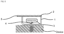
- FIG. 5 is a view schematically showing how an actuator according another exemplary embodiment of the present invention is attached.
- FIG. 6 is an exploded perspective view showing an actuator according to a first exemplary embodiment of the present invention.
- FIG. 7 is a perspective view of the actuator according to the first exemplary embodiment of the present invention.
- FIG. 8 is an exploded perspective view showing an actuator according to a second exemplary embodiment of the present invention.
- FIG. 9 is a perspective view of the actuator according to the second exemplary embodiment of the present invention.
- FIG. 10 is an exploded perspective view showing an actuator according to a third exemplary embodiment of the present invention.
- FIG. 11 is a perspective view of the actuator according to the third exemplary embodiment of the present invention.
- FIG. 12 is an exploded perspective view showing an actuator according to a fourth exemplary embodiment of the present invention.
- FIG. 13 is a graph comparing the vibration force transmitted by a second casing according to the conventional art attached to an electronic device and the vibration force transmitted by a first casing according to the present invention attached to an electronic device.
- FIG. 14 is a graph comparing the vibration acceleration according to the conventional art and the vibration acceleration according to the present invention.
- FIGS. 4 and 5 are views schematically showing the installation of a sound and vibration generating device using a vibration actuator according to the present invention.
- the vibration actuator roughly includes a first casing 1 whose sidewalls and bottom are integrated together and a second casing 2 affixed to the first casing 1 and forming a top.
- a vibrating body 3 is mounted in the inside space of the first casing 1 and second casing 2 , and the vibrating body 3 is held by an elastic member 4 .
- the elastic member 4 may be mounted between the first casing 1 and the vibrating body 3 or between the second casing 2 and the vibrating body 3 .
- the bottom of the first casing 1 is a surface that is attached to an electronic device.
- the first casing 1 has higher rigidity than the second casing 2 since it includes the bottom and sidewalls.
- the first casing 1 is less bent when the actuator transmits vibration force to the electronic device through the bottom of the first casing 1 , thus reducing loss of vibration force.
- FIG. 6 is an exploded perspective view showing an actuator according to a first exemplary embodiment of the present invention.
- FIG. 7 is a perspective view of the actuator according to the first exemplary embodiment of the present invention.
- the actuator roughly includes a first casing 100 having sidewalls 120 and a bottom 110 and a second casing 200 affixed to the first casing 100 and forming a top.
- a vibration-generating component is placed within an interior space formed by the first casing 100 and the second casing 200 .
- a vibrating body comprises a yoke 310 , a center magnet 320 attached onto the yoke 310 , a side magnet 330 placed around the center magnet 320 , a center plate 340 attached onto the center magnet 320 , and a side plate 350 attached onto the side magnet 330 .
- the vibrating body is supported by an elastic member 400 , and the lower end of the elastic member 400 is attached to the vibrating body and the upper end is attached to the bottom of the second casing 200 .
- a voice coil 600 is placed in a magnetic gap between the center magnet 320 and the side magnet 330 , and the voice coil 600 is a stator that is fixed to the second casing 200 .
- a printed circuit board 500 is attached to the voice coil 600 to transmit an electrical signal.
- the printed circuit board 500 has an extension 510 that is extended and pulled out of the space formed by the first casing 100 and the second casing 200 , and the extension 510 is formed with a land portion 512 where soldering is done to electrically connect it to an external power source.
- the first casing 100 having the sidewalls 120 and the bottom 110 serves as a surface that is attached to the electronic device, and the printed circuit board 500 is attached to the second casing 200 to make it easy to connect it to the voice coil 600 and attach the printed circuit board 500 to the inside of the casing.
- an L-shaped auxiliary plate 700 is further included to fix and hold the extension 510 of the printed circuit board 500 .
- the L-shaped auxiliary plate 700 is attached to an outer surface of a sidewall 120 of the first casing 100 .
- the auxiliary plate 700 is fixed to the first casing 100 by welding, bonding, etc.
- the printed circuit board 500 is attached to an inner surface of the second casing 200 , and the extension 510 of the printed circuit board 500 is pulled out between the first casing 100 and the second casing 200 and fixed to the L-shaped plate 700 .
- the L-shaped plate 700 comprises a first surface 710 fixed to the sidewall 120 and a second surface 720 bent at a right angle to the first surface 710 and attached to the electronic device.
- the land portion 512 is positioned on the second surface 720 .
- FIG. 8 is an exploded perspective view showing an actuator according to a second exemplary embodiment of the present invention.
- FIG. 9 is a perspective view of the actuator according to the second exemplary embodiment of the present invention.
- the parts mounted in the casings are identical to those of the first exemplary embodiment, except for the shapes of the first casing 100 a and second casing 200 a , so descriptions thereof will be omitted.
- the second casing 200 a has an extension 210 a attached to a removed area 122 a , which is formed by bending part of the second casing 200 a .
- the second casing 200 a has an attachment 220 a , which is formed by bending and extending the second casing 200 a once more at the bottom edge of the second casing 210 a .
- the attachment 220 a together with the first casing 100 a , may be attached to the electronic device.
- the extension 210 a is formed with a pull-out hole 212 a for pulling out the extension 510 of the printed circuit board 500 .
- the extension 510 of the printed circuit board 500 may be pulled out through the pull-out hole 212 a , thus allowing an external power source or the like to be connected to the extension 510 on the attachment 220 a by a method such as soldering.
- FIG. 10 is an exploded perspective view showing an actuator according to a third exemplary embodiment of the present invention.
- FIG. 11 is a perspective view of the actuator according to the third exemplary embodiment of the present invention.
- the parts mounted in the casings are identical to those of the first exemplary embodiment, except for the shapes of the first casing 100 b and second casing 200 b , so descriptions thereof will be omitted.
- the first casing 110 b has an extension 112 b which is as wide as a removed area 122 b and formed by extending the bottom 110 b further outward.
- the second casing 200 b has an extension 210 b , which is formed by bending and extending part of the second casing 200 b downward, and the extension 210 b of the second casing 200 b is connected to the removed area 122 b from which the sidewall 120 b is removed.
- the extension 210 b is formed with a pull-out hole 212 b for pulling out the extension 510 of the printed circuit board 500 .
- the extension 510 of the printed circuit board 500 is pulled out through the pull-out hole 212 b and attached to the extension 210 b of the second casing 200 b and the extension 112 b of the first casing 100 b .
- an external power source or the like may be connected to the extension 510 of the printed circuit board 500 by a method such as soldering.
- FIG. 12 is an exploded perspective view showing an actuator according to a fourth exemplary embodiment of the present invention.
- the parts mounted in the casings are identical to those of the first exemplary embodiment, except for a flat auxiliary plate 800 attached to the bottom of the first casing 100 , so descriptions thereof will be omitted.
- an extension 820 is formed at the bottom of the first casing 100 , which has the same cross section as the first casing 100 and supports the second surface 720 of the L-shaped auxiliary plate 700 .
- FIG. 13 is a graph comparing the vibration force transmitted by a second casing according to the conventional art attached to an electronic device and the vibration force transmitted by a first casing according to the present invention attached to an electronic device. As shown in the graph, it is evident that the transmission of vibration force through the first casing with sidewalls is better, especially at high frequencies, compared to the transmission of vibration force through the second casing.
- FIG. 14 is a graph comparing the vibration acceleration according to the conventional art and the vibration acceleration according to the present invention. As shown in the graph, it is evident that the transmission of vibration force through the first casing causes less distortion in vibration and improves the efficiency of transmission of vibration force, thereby leading to better sound pressure compared to the conventional attachment method.
Landscapes
- Engineering & Computer Science (AREA)
- Physics & Mathematics (AREA)
- Acoustics & Sound (AREA)
- Signal Processing (AREA)
- Electromagnetism (AREA)
- Power Engineering (AREA)
- Microelectronics & Electronic Packaging (AREA)
- Chemical & Material Sciences (AREA)
- Combustion & Propulsion (AREA)
- Mechanical Engineering (AREA)
- Multimedia (AREA)
- Health & Medical Sciences (AREA)
- Otolaryngology (AREA)
- Apparatuses For Generation Of Mechanical Vibrations (AREA)
Applications Claiming Priority (3)
| Application Number | Priority Date | Filing Date | Title |
|---|---|---|---|
| KR1020180143849 | 2018-11-20 | ||
| KR10-2018-0143849 | 2018-11-20 | ||
| KR1020180143849A KR102167493B1 (ko) | 2018-11-20 | 2018-11-20 | 액추에이터 |
Publications (2)
| Publication Number | Publication Date |
|---|---|
| US20200162822A1 US20200162822A1 (en) | 2020-05-21 |
| US11115754B2 true US11115754B2 (en) | 2021-09-07 |
Family
ID=70727180
Family Applications (1)
| Application Number | Title | Priority Date | Filing Date |
|---|---|---|---|
| US16/683,754 Active US11115754B2 (en) | 2018-11-20 | 2019-11-14 | Actuator |
Country Status (3)
| Country | Link |
|---|---|
| US (1) | US11115754B2 (zh) |
| KR (1) | KR102167493B1 (zh) |
| CN (1) | CN111200773B (zh) |
Families Citing this family (2)
| Publication number | Priority date | Publication date | Assignee | Title |
|---|---|---|---|---|
| KR102491847B1 (ko) * | 2020-10-28 | 2023-01-26 | 주식회사 이엠텍 | 마그넷 탈락 방지 구조를 구비하는 마이크로스피커 |
| CN113114808B (zh) * | 2021-04-07 | 2024-02-02 | 维沃移动通信有限公司 | 电子设备及振动模组 |
Citations (16)
| Publication number | Priority date | Publication date | Assignee | Title |
|---|---|---|---|---|
| JP2004104327A (ja) | 2002-09-06 | 2004-04-02 | Hosiden Corp | 圧電スピーカ用アクチュエータ |
| KR20060089454A (ko) | 2005-02-04 | 2006-08-09 | 삼성전기주식회사 | 진동 엑츄에이터 |
| CN101141828A (zh) | 2006-09-08 | 2008-03-12 | 雅马哈株式会社 | 传声器模块和适于便携式电子装置的安装结构 |
| US20110018365A1 (en) | 2009-07-22 | 2011-01-27 | Yong Jin Kim | Horizontal linear vibrator |
| US20110309691A1 (en) * | 2010-06-16 | 2011-12-22 | Samsung Electro-Mechanics Co., Ltd. | Linear vibrator and electronic device having the same |
| CN102740186A (zh) | 2011-03-31 | 2012-10-17 | 英业达股份有限公司 | 音频界面结构与使用该结构的电子装置 |
| US20140152126A1 (en) * | 2009-07-22 | 2014-06-05 | Samsung Electro-Mechanics Co., Ltd. | Horizontal linear vibrator |
| KR20150108459A (ko) | 2014-03-17 | 2015-09-30 | 주식회사 이엠텍 | 진동부 조립성이 향상된 선형 진동자 |
| KR20150140134A (ko) | 2014-06-05 | 2015-12-15 | 엘지전자 주식회사 | 이동 단말기 |
| KR20160067344A (ko) | 2014-12-04 | 2016-06-14 | 이인호 | 초소형 복합 진동 마이크로스피커 |
| CN206524961U (zh) | 2017-01-20 | 2017-09-26 | 瑞声科技(新加坡)有限公司 | 扬声器 |
| US20180021812A1 (en) * | 2016-07-25 | 2018-01-25 | Nidec Seimitsu Corporation | Vibration motor |
| CN107889036A (zh) | 2017-12-18 | 2018-04-06 | 陈火 | 一种低漏音骨传导扬声器单元 |
| US20190014416A1 (en) * | 2016-02-18 | 2019-01-10 | Yeil Electronics Co., Ltd. | Vibration output device having improved structure and portable electronic device comprising same |
| US20190151896A1 (en) * | 2017-11-17 | 2019-05-23 | Mitsumi Electric Co., Ltd. | Vibration actuator and portable device |
| US20200001326A1 (en) * | 2017-01-27 | 2020-01-02 | Mitsumi Electric Co., Ltd. | Vibration device, wearable terminal and incoming call notification device |
-
2018
- 2018-11-20 KR KR1020180143849A patent/KR102167493B1/ko active IP Right Grant
-
2019
- 2019-11-14 US US16/683,754 patent/US11115754B2/en active Active
- 2019-11-18 CN CN201911127565.5A patent/CN111200773B/zh active Active
Patent Citations (16)
| Publication number | Priority date | Publication date | Assignee | Title |
|---|---|---|---|---|
| JP2004104327A (ja) | 2002-09-06 | 2004-04-02 | Hosiden Corp | 圧電スピーカ用アクチュエータ |
| KR20060089454A (ko) | 2005-02-04 | 2006-08-09 | 삼성전기주식회사 | 진동 엑츄에이터 |
| CN101141828A (zh) | 2006-09-08 | 2008-03-12 | 雅马哈株式会社 | 传声器模块和适于便携式电子装置的安装结构 |
| US20110018365A1 (en) | 2009-07-22 | 2011-01-27 | Yong Jin Kim | Horizontal linear vibrator |
| US20140152126A1 (en) * | 2009-07-22 | 2014-06-05 | Samsung Electro-Mechanics Co., Ltd. | Horizontal linear vibrator |
| US20110309691A1 (en) * | 2010-06-16 | 2011-12-22 | Samsung Electro-Mechanics Co., Ltd. | Linear vibrator and electronic device having the same |
| CN102740186A (zh) | 2011-03-31 | 2012-10-17 | 英业达股份有限公司 | 音频界面结构与使用该结构的电子装置 |
| KR20150108459A (ko) | 2014-03-17 | 2015-09-30 | 주식회사 이엠텍 | 진동부 조립성이 향상된 선형 진동자 |
| KR20150140134A (ko) | 2014-06-05 | 2015-12-15 | 엘지전자 주식회사 | 이동 단말기 |
| KR20160067344A (ko) | 2014-12-04 | 2016-06-14 | 이인호 | 초소형 복합 진동 마이크로스피커 |
| US20190014416A1 (en) * | 2016-02-18 | 2019-01-10 | Yeil Electronics Co., Ltd. | Vibration output device having improved structure and portable electronic device comprising same |
| US20180021812A1 (en) * | 2016-07-25 | 2018-01-25 | Nidec Seimitsu Corporation | Vibration motor |
| CN206524961U (zh) | 2017-01-20 | 2017-09-26 | 瑞声科技(新加坡)有限公司 | 扬声器 |
| US20200001326A1 (en) * | 2017-01-27 | 2020-01-02 | Mitsumi Electric Co., Ltd. | Vibration device, wearable terminal and incoming call notification device |
| US20190151896A1 (en) * | 2017-11-17 | 2019-05-23 | Mitsumi Electric Co., Ltd. | Vibration actuator and portable device |
| CN107889036A (zh) | 2017-12-18 | 2018-04-06 | 陈火 | 一种低漏音骨传导扬声器单元 |
Also Published As
| Publication number | Publication date |
|---|---|
| CN111200773A (zh) | 2020-05-26 |
| KR20200059029A (ko) | 2020-05-28 |
| CN111200773B (zh) | 2022-06-17 |
| KR102167493B1 (ko) | 2020-10-19 |
| US20200162822A1 (en) | 2020-05-21 |
Similar Documents
| Publication | Publication Date | Title |
|---|---|---|
| US9503805B2 (en) | Piezoelectric ceramic dual-frequency earphone structure | |
| US8774448B2 (en) | Speaker with elastic plate coupled to diaphragm | |
| US7557474B2 (en) | Electromagnetic exciter | |
| CN111405431B (zh) | 发声器件及其扬声器箱 | |
| US9807512B2 (en) | Speaker | |
| EP1791391A2 (en) | Speaker for mobile communication terminal | |
| KR102167474B1 (ko) | 하이브리드 액추에이터 | |
| US11115754B2 (en) | Actuator | |
| US20230224642A1 (en) | Loudspeaker and earphone | |
| US11109132B2 (en) | Screen sound generation device | |
| US11206490B2 (en) | Sound generating actuator | |
| US10674274B2 (en) | Speaker | |
| KR102214664B1 (ko) | 음향 발생 액츄에이터 | |
| KR102183882B1 (ko) | 하이브리드 액추에이터 | |
| US8141675B2 (en) | Micro-speaker | |
| US20200045428A1 (en) | Speaker | |
| KR20190100832A (ko) | 하이브리드 액추에이터 및 이를 구비하는 멀티 미디어 장치 | |
| US8891808B2 (en) | Micro-speaker | |
| KR102190412B1 (ko) | 마이크로 스피커 | |
| US10674277B2 (en) | Speaker | |
| JP2001309007A (ja) | 電気音響変換器 | |
| KR20240107934A (ko) | 드라이버 유닛용 프로텍터 | |
| KR100511218B1 (ko) | 전자음향변환기의 구조 | |
| KR20210018657A (ko) | 음향 발생 액츄에이터 | |
| KR200304258Y1 (ko) | 전자음향변환기의 구조 |
Legal Events
| Date | Code | Title | Description |
|---|---|---|---|
| FEPP | Fee payment procedure |
Free format text: ENTITY STATUS SET TO UNDISCOUNTED (ORIGINAL EVENT CODE: BIG.); ENTITY STATUS OF PATENT OWNER: LARGE ENTITY |
|
| STPP | Information on status: patent application and granting procedure in general |
Free format text: NON FINAL ACTION MAILED |
|
| STPP | Information on status: patent application and granting procedure in general |
Free format text: RESPONSE TO NON-FINAL OFFICE ACTION ENTERED AND FORWARDED TO EXAMINER |
|
| STPP | Information on status: patent application and granting procedure in general |
Free format text: FINAL REJECTION MAILED |
|
| STPP | Information on status: patent application and granting procedure in general |
Free format text: RESPONSE AFTER FINAL ACTION FORWARDED TO EXAMINER |
|
| STPP | Information on status: patent application and granting procedure in general |
Free format text: NOTICE OF ALLOWANCE MAILED -- APPLICATION RECEIVED IN OFFICE OF PUBLICATIONS |
|
| STPP | Information on status: patent application and granting procedure in general |
Free format text: AWAITING TC RESP., ISSUE FEE NOT PAID |
|
| STPP | Information on status: patent application and granting procedure in general |
Free format text: NOTICE OF ALLOWANCE MAILED -- APPLICATION RECEIVED IN OFFICE OF PUBLICATIONS |
|
| STPP | Information on status: patent application and granting procedure in general |
Free format text: PUBLICATIONS -- ISSUE FEE PAYMENT VERIFIED |
|
| STCF | Information on status: patent grant |
Free format text: PATENTED CASE |