US11115258B2 - Method to implicitly indicate system information in NR - Google Patents
Method to implicitly indicate system information in NR Download PDFInfo
- Publication number
- US11115258B2 US11115258B2 US16/464,082 US201616464082A US11115258B2 US 11115258 B2 US11115258 B2 US 11115258B2 US 201616464082 A US201616464082 A US 201616464082A US 11115258 B2 US11115258 B2 US 11115258B2
- Authority
- US
- United States
- Prior art keywords
- signaling
- sequence
- sub
- synchronization
- sequences
- Prior art date
- Legal status (The legal status is an assumption and is not a legal conclusion. Google has not performed a legal analysis and makes no representation as to the accuracy of the status listed.)
- Active
Links
Images


Classifications
-
- H—ELECTRICITY
- H04—ELECTRIC COMMUNICATION TECHNIQUE
- H04L—TRANSMISSION OF DIGITAL INFORMATION, e.g. TELEGRAPHIC COMMUNICATION
- H04L5/00—Arrangements affording multiple use of the transmission path
- H04L5/003—Arrangements for allocating sub-channels of the transmission path
- H04L5/0048—Allocation of pilot signals, i.e. of signals known to the receiver
-
- H—ELECTRICITY
- H04—ELECTRIC COMMUNICATION TECHNIQUE
- H04L—TRANSMISSION OF DIGITAL INFORMATION, e.g. TELEGRAPHIC COMMUNICATION
- H04L27/00—Modulated-carrier systems
- H04L27/26—Systems using multi-frequency codes
-
- H—ELECTRICITY
- H04—ELECTRIC COMMUNICATION TECHNIQUE
- H04L—TRANSMISSION OF DIGITAL INFORMATION, e.g. TELEGRAPHIC COMMUNICATION
- H04L27/00—Modulated-carrier systems
- H04L27/26—Systems using multi-frequency codes
- H04L27/2601—Multicarrier modulation systems
- H04L27/2602—Signal structure
- H04L27/261—Details of reference signals
- H04L27/2613—Structure of the reference signals
- H04L27/26136—Pilot sequence conveying additional information
-
- H—ELECTRICITY
- H04—ELECTRIC COMMUNICATION TECHNIQUE
- H04L—TRANSMISSION OF DIGITAL INFORMATION, e.g. TELEGRAPHIC COMMUNICATION
- H04L27/00—Modulated-carrier systems
- H04L27/26—Systems using multi-frequency codes
- H04L27/2601—Multicarrier modulation systems
- H04L27/2647—Arrangements specific to the receiver only
- H04L27/2655—Synchronisation arrangements
- H04L27/2666—Acquisition of further OFDM parameters, e.g. bandwidth, subcarrier spacing, or guard interval length
-
- H—ELECTRICITY
- H04—ELECTRIC COMMUNICATION TECHNIQUE
- H04L—TRANSMISSION OF DIGITAL INFORMATION, e.g. TELEGRAPHIC COMMUNICATION
- H04L5/00—Arrangements affording multiple use of the transmission path
- H04L5/0091—Signaling for the administration of the divided path
- H04L5/0092—Indication of how the channel is divided
-
- H—ELECTRICITY
- H04—ELECTRIC COMMUNICATION TECHNIQUE
- H04L—TRANSMISSION OF DIGITAL INFORMATION, e.g. TELEGRAPHIC COMMUNICATION
- H04L27/00—Modulated-carrier systems
- H04L27/26—Systems using multi-frequency codes
- H04L27/2601—Multicarrier modulation systems
- H04L27/2647—Arrangements specific to the receiver only
- H04L27/2655—Synchronisation arrangements
- H04L27/2689—Link with other circuits, i.e. special connections between synchronisation arrangements and other circuits for achieving synchronisation
- H04L27/2692—Link with other circuits, i.e. special connections between synchronisation arrangements and other circuits for achieving synchronisation with preamble design, i.e. with negotiation of the synchronisation sequence with transmitter or sequence linked to the algorithm used at the receiver
Definitions
- the present disclosure pertains to wireless communication technology, in particular in the context of synchronisation signaling.
- New approaches to wireless communication technology are being introduced, e.g. in the context of 3GPPs 5G technologies like New Radio (NR) or LTE Evolution. These approaches in many cases lead to highly flexible systems. However, with high flexibility may be detrimental to speed of the system, and/or incur inefficiencies in particular by introducing control signaling overhead.
- 5G technologies like New Radio (NR) or LTE Evolution.
- RAN radio access network
- LTE Evolution in particular, LTE Rel. 14 and later
- NR NR
- a method for operating a network node in a radio access network comprising transmitting synchronisation signaling, the synchronisation signaling comprising a signaling sequence, the signaling sequence being determined as a combination of a number of sub-sequences, wherein an order of the sub-sequences is mapped to synchronisation information.
- the method may comprise configuring a user equipment with a corresponding mapping.
- a network node for a radio access network may be considered.
- the network node may be adapted for transmitting synchronisation signaling, the synchronisation signaling comprising a signaling sequence, the signaling sequence being determined as a combination of a number of sub-sequences, wherein an order of the sub-sequences is mapped to synchronisation information.
- the network node may comprise, and/or be adapted for using, processing circuitry and/or radio circuitry, in particular a transmitter, for such transmitting. Alternatively or additionally, the network node may comprise a transmitting module for such transmitting.
- the network node may be adapted for configuring a user equipment with a corresponding mapping, and/or for using processing circuitry and/or radio circuitry for such configuring, and/or may comprise a configuring module for such configuring.
- a method for operating a user equipment in a radio access network comprises determining synchronisation information based on received synchronisation signaling, the synchronisation signaling comprising a signaling sequence, which is composed of a combination of a number of sub-sequences, wherein an order of the sub-sequences is mapped to the synchronisation information.
- a user equipment for a radio access network is also described.
- the user equipment is adapted for determining synchronisation information based on received synchronisation signaling, the synchronisation signaling comprising a signaling sequence, which is composed of a combination of a number of sub-sequences, wherein an order of the sub-sequences is mapped to the synchronisation information.
- the user equipment may comprise, and/or be adapted for using, processing circuitry and/or radio circuitry, in particular a receiver, for such determining. Additionally or alternatively, the user equipment may comprise a determining module for such determining.
- Determining the synchronisation information may comprise, and/be based on, demodulating and/decoding and/or detecting the synchronisation signaling or the sequence or subsequences, respectively. This may comprise determining a best hypothesis for the signaling or (sub-)sequences to determine a correct (or best) signaling sequence.
- the synchronisation signaling may repeat, within a time interval, the signaling sequence.
- the order of the sub-sequence may change between repetitions. It may be considered that the time interval comprises or represents a subframe and/or slot and/or transmission time interval and/or synchronisation signaling block or synchronisation signaling burst or burst set.
- the sequence may be mapped to different subcarriers of the same symbol or different symbols.
- Mapping of the sequence may comprise mapping the subsequences, e.g. to subcarriers and/or resource elements. For different repetitions of the sequence, different mappings of the (same) subsequences to the (same) subcarriers may be used.
- Each sub-sequence may generally be chosen from a set of subsequences. It may be considered that each set of subsequences is different from the other sets. A set may be considered to be different from another set if it contains at least one sub-sequence not in the other subset, or vice versa. Different subsets may comprise the same or different numbers of subsequences. In some variants, each subset may contain unique subsequences not contained in any other subset. This allows particularly easy identification.
- a sub-sequence from each set (a chosen subsequence) is mapped to a subcarrier.
- a sub-sequence may generally comprise one or more signals, which may be adapted in some variant to have each (e.g., significantly) shorter duration than a symbol time interval.
- Synchronisation signaling may be considered to be different in types of transmission mode and/or modulation than symbols (e.g. OFDM symbols) of normal operation, e.g. during data transmission. It may be considered that synchronisation signaling is associated to, and/or transmitted and/or received on, a broadcast channel, in particular a physical broadcast channel, e.g. a PBCH according to a 3GPP standard like LTE or NR, and/or a similar channel according to another standard. The channel may be part of, and/or be associated to the cell the synchronisation signaling is associated to.
- program product comprising instructions causing processing circuitry to carry out and/or control performing of any one of the methods discussed herein.
- the instructions may be provided in form of code, and/or may be executable by the processing circuitry.
- a carrier medium arrangement carrying and/or storing a program product described herein is also proposed.
- a carrier medium arrangement may comprise one or more carrier media.
- a carrier medium may be accessible and/or readable and/or receivable by processing circuitry. Storing data and/or a program product and/or code and/or instructions may be considered part of carrying data and/or a program product and/or code and/or instructions.
- a carrier medium generally may comprise a guiding/transporting medium and/or a storage medium.
- a guiding/transporting medium may be adapted to carry and/or carry and/or store signals, in particular electromagnetic signals and/or electrical signals and/or magnetic signals and/or optical signals.
- a carrier medium in particular a guiding/transporting medium, may be adapted to guide such signals to carry them.
- a carrier medium, in particular a guiding/transporting medium may comprise the electromagnetic field, e.g. radio waves or microwaves, and/or optically transmissive material, e.g. glass fiber, and/or cable.
- a storage medium may comprise at least one of a memory, which may be volatile or non-volatile, a buffer, a cache, an optical disc, magnetic memory, flash memory, etc.
- Synchronisation signaling may comprise one or more signals or symbols.
- synchronisation signaling may comprise a signaling or symbol series, and/or a signaling sequence.
- a series and/or the signaling may comprise one or more sequences, and in particular may repeat one sequence a once or more, e.g. in a burst or burst set.
- a signaling sequence may be defined by its subsequences, of which it may be composed. Different sequences may comprise different subsequences, in particular may differ in at least on subsequence. It should be noted that the order of the subsequences in the sequence may not be considered to define the sequence. Thus, different orders of the same subsequences may be considered to represent the same sequence.
- a set of subsequences may comprise one or more subsequences.
- An order may in particular pertain to an interleaving order, respectively pertain to an order or arrangement or mapping of the subsequences to subcarriers.
- a symbol as described herein may in particular be an OFDM symbol, or a DFTS-symbol, and/or may represent a symbol time interval, e.g. according to a standard mentioned herein.
- mapping is represented by a table and/or relation and/or function.
- the mapping may be represented in a memory and/or configured to a user equipment, e.g. by a network node.
- the user equipment may be adapted for receiving a corresponding configuration, and/or may be adapted for using processing circuitry and/or radio circuitry, in particular a receiver, for such receiving. Alternatively or additionally, it may comprise a corresponding receiving module.
- Synchronisation information may generally comprise information pertaining to synchronisation and/or cell search and/or transmission mode and/or measurements, in particular pertaining to the cell the synchronisation signaling the synchronisation signaling is associated to.
- Examples of synchronisation information comprise information indicating a location and/or timing and/or symbol or burst or block number or index (relative to a related time interval) and/or cell information, a cell ID and/or physical cell ID, and/or periodicity of the signaling, e.g. of burst or blocks.
- Information pertaining to transmission mode may for example indicate modulation scheme and/or duplex mode and/or requirements on the UE (e.g., regarding power class and/or capabilities) used for the cell and/or characteristic/s capability/ies of the network node or the cell.
- the synchronisation signaling may be secondary synchronisation signaling, accessible (decodable and/or demodulatable) after decoding and/or demodulating primary synchronisation signaling.
- Synchronisation signaling may be transmitted and/or associated to a synchronisation frequency interval, which may comprise a plurality of subcarriers. For example, 6 or 12 or more subcarriers may be associated to the synchronisation signaling.
- a resource element may generally describe the smallest individually usable and/or encodable and/or decodable and/or modulatable and/or demodulatable time-frequency resource, and/or may describe a time-frequency resource covering a symbol time length in time and a subcarrier in frequency.
- a signal may be allocatable and/or allocated to a resource element.
- a subcarrier may be a subband of a carrier, e.g. as defined by a standard.
- a carrier may define a frequency and/or frequency band for transmission and/or reception.
- a carrier may be associated to a cell and/or one or more (physical) channels.
- a radio node may generally be considered a device or node adapted for wireless and/or radio (and/or microwave) frequency communication, and/or for communication utilising an air interface, e.g. according to a communication standard.
- a network node or a user equipment or terminal may be considered a radio node.
- a network node may be any radio node of a wireless communication network, e.g. a base station and/or gNodeB (gNB) and/or relay node and/or micro/nano/pico/femto node and/or other node, in particular for a RAN as described herein.
- a radio node may generally comprise a memory storing information indicating the mapping and/or the sequences and/or the subsequences and/or the sets.
- a user equipment or terminal may represent and end device for communication utilising the wireless communication network, and/or be implemented as a user equipment according to a standard.
- Examples of user equipments may comprise a phone like a smartphone, a personal communication device, a mobile phone or terminal, a computer, in particular laptop, a sensor or machine with radio capability (and/or adapted for the air interface), in particular for MTC (Machine-Type-Communication, sometimes also referred to M2M, Machine-To-Machine), or a vehicle adapted for wireless communication.
- a user equipment may be mobile or stationary.
- a radio node may generally comprise processing circuitry and/or radio circuitry.
- Circuitry may comprise integrated circuitry.
- Processing circuitry may comprise one or more processors and/or controllers (e.g., microcontrollers), and/or ASICs (Application Specific Integrated Circuitry) and/or FPGAs (Field Programmable Gate Array), or similar. It may be considered that processing circuitry comprises, and/or is (operatively) connected or connectable to one or more memories or memory arrangements.
- a memory arrangement may comprise one or more memories.
- a memory may be adapted to store digital information.
- Examples for memories comprise volatile and non-volatile memory, and/or Random Access Memory (RAM), and/or Read-Only-Memory (ROM), and/or magnetic and/or optical memory, and/or flash memory, and/or harddisk memory, and/or EPROM or EEPROM (Erasable Programmable ROM or Electrically Erasable Programmable ROM).
- Radio circuitry may comprise one or more transmitters and/or receivers and/or transceivers (which may operate as transmitter and receiver), and/or may comprise one or more amplifiers and/or oscillators and/or filters, and/or may comprise, and/or be connected or connectable to antenna circuitry and/or one or more antennas.
- a radio node may be adapted for using its processing circuitry and/or radio circuitry to perform any of the methods described herein and associated to it.
- modules disclosed herein may be implemented in software and/or firmware and/or hardware. Different modules may be associated to different components of a radio node, e.g. different circuitries or different parts of a circuitry. It may be considered that a module is distributed over different components.
- FIG. 1 showing an example of synchronisation signaling in LTE
- FIG. 2 showing schematically a cell search procedure for LTE release 8;
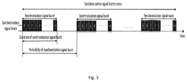
- FIG. 3 showing an illustration of a SS block, SS burst and SS burst set
- FIG. 4 showing a sub-sequences selection from Q sub-sequence sets
- FIG. 5 showing SSS construction with different SSCs interleaving orders
- FIG. 6 showing SSS detection with sub-sequence and interleaving order detection
- FIG. 7 showing exemplary PSS/SSS allocation with interleaving order to indicate OFDM symbol index in one subframe
- FIG. 8 showing a SS block with interleaving order to indicate a time index in one SS burst
- FIG. 9 showing an exemplary user equipment
- FIG. 10 showing an exemplary network node.
- the PSS and SSS are used at cell search in the UE for LTE.
- the PSS is transmitted in the last OFDM symbol of slots 0 and 10 within a frame and the SSS is transmitted in the OFDM symbol preceding PSS, as shown in FIG. 1 .
- the PSS is transmitted in the third OFDM symbol of slots 3 and 13 within a frame, and the SSS is transmitted in the last OFDM symbol of slots 2 and 12 , i.e., three symbols ahead of the PSS.
- FIG. 2 A simplified initial cell search procedure is illustrated in FIG. 2 .
- the UE tries to detect PSS from which it can derive the cell identity within a cell-identity group, which consists of three different cell identities corresponding to three different PSS. In this detection, the UE thus has to blindly search for all of these three possible cell identities.
- the UE also achieves OFDM symbol synchronization and a coarse frequency offset estimation with an accuracy of about 1 kHz. The latter is estimated by the UE by evaluating several hypotheses of the frequency error.
- the UE can then continue to detect SSS (coherent detection may be performed due to PSS having been decoded) from which it acquires the physical cell id and achieves radio frame synchronization.
- SSS coherent detection may be performed due to PSS having been decoded
- the UE also detects if a transmission mode with normal or extended cyclic prefix is used. If the UE is not preconfigured for either TDD or FDD, the UE can detect the duplex mode by the position of the detected SSS in the frame in relation to detected PSS.
- Fine frequency offset estimation can be estimated by correlating PSS and SSS. Alternatively, this fine frequency offset estimation is estimated by using the Cell specific Reference Signals (CRS) which are derived from the Physical Cell Identity (PCI) encoded in the PSS/SSS.
- CRS Cell specific Reference Signals
- PCI Physical Cell Identity
- NR-PSS may provide the basic functionality of facilitating time and frequency synchronization for the initial access or cell search, similar to the PSS and SSS, respectively.
- NR-SSS may provide the basic functionality of facilitating time and frequency synchronization for the initial access or cell search, similar to the PSS and SSS, respectively.
- initial downlink synchronization may be provided with a pre-defined sequence of signaling.
- NR there are various requirements in NR, including such aimed at energy saving, various numerologies and high carrier frequencies.
- the transmission on periodical and static signals may be needed to be decreased and should be more flexible in various aspects.
- the synchronization signals may be transmitted periodically in downlink for UEs to obtain the downlink synchronization, to allow following demodulation or decoding of the relevant system and random access information.
- NR-PSS may be transmitted within a SS (Synchronisation Signaling) block.
- SS Synchronisation Signaling
- One or multiple SS block(s) may compose an SS burst, and one or multiple SS burst(s) may compose a SS burst set, as shown in FIG. 3 .
- a new design of synchronization signaling, in particular secondary synchronisation signaling is proposed, which may comprise a (signal) sequence to implicitly deliver information, such as OFDM symbol offset and SS block time index information.
- information may be (implicitly) indicated to a UE by an interleaving orders of pre-defined sets of component sequences, such that different interleaving orders may represent different information.
- This approach does not require extra information bits to be delivered to indicate the information, such as SS block time index. Moreover, it is flexible to be extended to support more information delivery without explicit information bits and is considered to have low detection complexity.
- secondary synchronisation signaling An exemplary construction on the synchronization signaling is described in the following, based on the sequence design proposal, as well as a detection algorithm and the usage of the implicit information. It is referred to secondary synchronisation signaling by way of example, but the approach or design may be implemented for other synchronisation signaling as well, in particular tertiary synchronisation signaling, if implemented. Generally, secondary synchronisation signaling may be considered to refer to synchronisation signaling of any order higher than primary, and/or require (successful) synchronisation to at least primary synchronisation signaling.
- a secondary synchronization signaling sequence can be transmitted on one symbol, e.g. one OFDM symbol.
- Its length, L ss is not larger than the number of resource elements reserved, N ss , i.e., L ss ⁇ N ss .
- N ss the number of resource elements reserved
- the bandwidth reserved for the synchronization signal might be different, e.g. larger.
- K ss of basic system information e.g., K ss cell identities may be mapped to and/or assigned to, sequences, and the equivalent number of information bits of such sequence-based delivery can be regarded as ⁇ log 2 K ss ⁇ .
- K ss 168 is defined to indicate the selected identity of the group for a cell, where three identities are further delivered by PSS.
- K C K SS Q candidate sub-sequences in each sub-sequence set (which also indicates that there are total QK c sub-sequences from all sets in total).
- a component sequence can be flexibly selected, and in this proposal, a BPSK-modulated m-sequence may represent a component sequence. However, other types of modulation may be used for a sequence.
- Q component sequences may be selected from the Q sub-sequence sets one by one.
- the selected sub-sequence in the q th set is denoted as SSC k q (q) , 0 ⁇ q ⁇ Q ⁇ 1, wherein k q is the sequence index in the q tk set, 0 ⁇ k q ⁇ K c ⁇ 1.
- the selection procedure is illustrated in FIG. 4 .
- a group ID k is may be indicated by a vector ⁇ k 0 , k 1 , . . . , k Q ⁇ 1 ⁇ , which may be pre-defined or determined before being interleaved to construct the final sequence.
- the next step is to further construct the sequence with these component sequences with a certain interleaving order.
- An order in this context may represent in which order the chosen sequences are arranged, e.g. interleaved.
- the first element of SSC k 0 (0) is followed by the first element of SSC k 1 (1) and the first element of SSC k 1 (2) in order, and so on for the following elements of the sub-sequences.
- the first element of SSC k 0 (0) is followed by the first element of SSC k 2 (2) and the first element of SSC k 1 (1) in order.
- the bandwidth reserved for the SS block is proposed to be larger than the PSS/SSS/PBCH in LTE, even on a carrier frequency lower than 6 GHz.
- N ss 288
- there are 24 interleaving orders which can be used to indicate the information implicitly without a complex detection algorithm, and the mapping between the order and the implicit information to be delivered should be pre-defined, which will be introduced in the following sections.
- NR-SSS NR-PSS successful detection, analogous to the approach shown in FIG. 2 .
- the SSS detection is done after the PSS detection, and the channel can therefore be assumed to be known (i.e. estimated based on the detected PSS sequence).
- the possible position of NR-SSS can be determined according to the predefined time and/or frequency offset in relation to the NR-PSS, and the corresponding samples can be converted to the frequency domain via FFT (Fast Fourier Transform) to further scan and detect the selected component subsequences from the sub-sequence sets.
- FFT Fast Fourier Transform
- the identity information e.g., cell id
- the order of the sub-sequences can be used to derive the implicit information, e.g., SS block index, according to a pre-defined mapping between the order and the implicit information.
- An exemplary detection procedure is illustrated in FIG. 6 .
- the time and frequency location of the allocated NR-SSS can be derived accordingly, which is analogous to the approach shown in FIG. 1 for LTE. Then, the received signals on a set of subcarriers may be selected for the following detection.
- the initial subcarrier set is decided and/or determined by the number of component sequence sets, i.e., one subcarrier may be selected in every Q subcarriers as illustrated in FIG. 5 . All the component sequences could be used to assist coherent or non-coherent detection.
- the best component sequence for each set may be selected.
- the detected component sequences can be integrated as the final NR-SSS sequence, whose identity is used to indicate the explicit information, e.g., cell ID.
- the order of the component sequences is used to indicate the implicit information as introduced in the next section.
- the NR-SSS sequence is composed by several different sub-sequences, which may be allocated in a comb manner in frequency domain, the sub-sequences can also be detected separately or jointly.
- Implicit indication with the interleaving order is discussed in the following.
- the usage of the interleaving order to indicate the information would be introduced by pre-defined a mapping between the order and the implicit information.
- OFDM Orthogonal Frequency Division Multiplexing
- massive MIMO Multiple Input, Multiple Output, a multi-antenna scheme
- the system design may consider to support massive beams (massive beams may refer to a large number of possible beam).
- beam sweeping in the time domain is a promising scheme to provide a wide coverage, especially for broadcast information and signals, e.g., NR-PSS and NR-SSS.
- NR-PSS NR-SSS
- NR-SSS For the same cell (or a logical coverage with some common system information), it is supposed to deliver the cell id in a time duration with beam sweeping.
- FIG. 7 shows the case in which NR-PSS and NR-SSS are combined and inserted into one OFDM symbol, and (b) shows the case that PSS is followed by SSS in separate OFDM symbols.
- NR-PSS and NR-SSS could be flexible.
- the NR-SSS in all OFDM symbols in the subframe may have the same component sequences (although they may be in different order), and may indicate the same explicit information, e.g., cell ID, together with the NR-PSS sequence.
- the interleaving order of the component sequences of NR-SSS is considered.
- the mapping between the interleaving order and the allocated OFDM symbol index in one subframe may be pre-defined.
- the subframe start point can be derived, which will be the basic time synchronization for the following system information acquisition and random access procedure.
- a SS block time index is discussed in the following.
- the ‘SS block’ can be regarded a combination of NR-PSS, NR-SSS and other key system information, such as for a MIB (Master Information Block) carried or transmitted on NR-PBCH (Physical Broadcast Channel).
- MIB Master Information Block
- NR-PBCH Physical Broadcast Channel
- the UE can obtain the system synchronization for the following signals and channels such as random access procedure, timing for other broadcast channels and time positions for paging messages.
- the position of one of the sequences e.g. SSC k 0 (0) , is used to indicate the number of a subframe within a radio frame. Then the position of a second sequence, e.g. SSC k 1 (1) may be used to indicate OFDM symbol position within a sub-frame.
- the order in the interleaving can be used to implicitly indicate other key system information without extra and explicit information bits, such as the indication for the periodicity of the SS burst occasion.
- the SS burst is designed to support multiple periodicities, which may be beneficial regarding different requirements on the system information acquisition delay. If the acquisition delay is expected to be as quick as possible, the periodicity of the SS block including the basic system information needs to be small. Otherwise, it can be larger to reduce the energy consumption and interference.
- the mapping between the interleaving order and the periodicity of SS burst is predefined, and UE can derive the periodicity according to the detection on the interleaving order, and prepare to detect the SS burst occasion when reaching the periodicity.
- the periodicity of SS blocks can be indicated by the number of interleaved sequences.
- two interleaved sequences can be used to indicate a 5 ms periodicity.
- An interleaving with three sequences may be used to indicate a periodicity of 10 ms (or any other predefined number).
- Four interleaved sequences may be used for yet another periodicity (e.g. 20 ms).
- the proposed synchronization signal is the NR-SSS sequence transmitted with interleaving order to deliver the system information, such as OFDM symbol offset, SS block time index and others.
- interleaving order can be changed between transmitting the same overall sequence repeatedly, such that information may be included by providing different orders of the same sequence components a plurality of times.
- FIG. 9 schematically shows a terminal 10 , which may be implemented as a UE (User Equipment).
- Terminal 10 comprises processing circuitry (which may also be referred to as control circuitry) 20 , which may comprise a controller connected to a memory. Any module of the terminal, e.g. a determining and/or receiving module, may be implemented in and/or executable by, the processing circuitry 20 , in particular as module in the controller.
- Terminal 10 also comprises radio circuitry 22 providing receiving and transmitting or transceiving functionality (e.g., one or more transmitters and/or receivers and/or transceivers), the radio circuitry 22 being connected or connectable to the control circuitry.
- receiving and transmitting or transceiving functionality e.g., one or more transmitters and/or receivers and/or transceivers
- An antenna circuitry 24 of the terminal 10 is connected or connectable to the radio circuitry 22 to collect or send and/or amplify signals.
- Radio circuitry 22 and the processing circuitry 20 controlling it are configured for cellular communication with a network, e.g. a RAN as described herein.
- Terminal 10 may generally be adapted to carry out any of the methods for operating a terminal or UE disclosed herein; in particular, it may comprise corresponding circuitry, e.g. processing circuitry, and/or modules.
- FIG. 10 schematically shows a network node 100 , which in particular may be an eNB, or gNB or similar for NR.
- Network node 100 comprises processing circuitry (which may also be referred to as control circuitry) 120 , which may comprise a controller connected to a memory. Any module, e.g. transmitting module and/or configuring module of the network node 100 may be implemented in and/or executable by the processing circuitry 120 .
- the processing circuitry 120 is connected to control radio circuitry 122 of the radio node 100 , which provides receiver and transmitter and/or transceiver functionality (e.g., comprising one or more transmitters and/or receivers and/or transceivers).
- An antenna circuitry 124 may be connected or connectable to radio circuitry 122 for signal reception or transmittance and/or amplification.
- the network node 100 may be adapted to carry out any of the methods for operating a network node disclosed herein; in particular, it may comprise corresponding circuitry, e.g. processing circuitry, and/or modules.
- the antenna 124 circuitry may be connected to and/or comprise an antenna array.
- the network node 100 respectively its circuitry, may be adapted to transmit configuration data and/or to configure a terminal as described herein.
- Configuring a user equipment or terminal may comprise transmitting, to the UE or terminal, signaling comprising configuration data indicating the configured information or a configuration, in particular a mapping.
- the data may indicate the information directly (e.g., by explicitly including or representing it) or indirectly (e.g., by providing a pointer to the information and/or indexing a table).
- the signaling may comprise one or more individual signal/s or may be in a message, which may indicate additional information.
- a cell may be generally a communication cell, e.g., of a cellular or mobile communication network, provided by a node.
- a serving cell may be a cell on or via which a network node (the node providing or associated to the cell, e.g., base station or eNodeB or gNodeB) transmits and/or may transmit synchronisation signaling and/or data to a user equipment, in particular control and/or user or payload data, and/or via or on which a user equipment transmits and/or may transmit data to the node;
- a serving cell may be a cell for or on which the user equipment is configured and/or to which it is synchronized and/or has performed an access procedure, e.g., a random access procedure, and/or in relation to which it is in a RRC_connected or RRC_idle state, e.g., in case the node and/or user equipment and/or network follow the LTE-standard.
- One or more carriers e.
- synchronisation signaling may comprise primary and secondary synchronisation signaling.
- LTE Long Term Evolution
- LTE-A LTE-Advanced
- NR wireless or wireless or cellular communications technologies
- LTE Long Term Evolution
- GSM Global System for Mobile Communications
- TSs Technical Specifications
- 3GPP Third Generation Partnership Project
- PM Performance Management
Abstract
Description
candidate sub-sequences in each sub-sequence set (which also indicates that there are total QKc sub-sequences from all sets in total). The qth sub-sequence set may be denoted as
SSC(q)={SSC0 (q),SSC1 (q), . . . , SSCK
where SSCm (q) means the mth sub-sequence, 0≤m≤Kc−1, in the qth sub-sequence set, 0≤q≤Q−1. If using the SSS in LTE as the reference, the parameters above can be derived as Q=2 for the two sub-sequence sets, and Lssc=31. To indicate the group id from the total 168 candidates, Kss=168, the candidates in either sets can be regarded as
SSSk={SSCk
| Abbreviation | Explanation | |
| UE | User equipment | |
| LTE | Long term evolution | |
| NR | New Radio | |
| 3GPP | 3rd Generation Partnership Project | |
| DL | Downlink | |
| UL | Uplink | |
| DC | Digital | |
| 5G | ||
| 5th generation of radio technology | ||
Claims (19)
Applications Claiming Priority (1)
| Application Number | Priority Date | Filing Date | Title |
|---|---|---|---|
| PCT/CN2016/112065 WO2018119563A1 (en) | 2016-12-26 | 2016-12-26 | A method to implicitly indicate system information in nr |
Publications (2)
| Publication Number | Publication Date |
|---|---|
| US20190288899A1 US20190288899A1 (en) | 2019-09-19 |
| US11115258B2 true US11115258B2 (en) | 2021-09-07 |
Family
ID=62707705
Family Applications (1)
| Application Number | Title | Priority Date | Filing Date |
|---|---|---|---|
| US16/464,082 Active US11115258B2 (en) | 2016-12-26 | 2016-12-26 | Method to implicitly indicate system information in NR |
Country Status (4)
| Country | Link |
|---|---|
| US (1) | US11115258B2 (en) |
| EP (1) | EP3560156B1 (en) |
| CN (1) | CN110100419B (en) |
| WO (1) | WO2018119563A1 (en) |
Families Citing this family (4)
| Publication number | Priority date | Publication date | Assignee | Title |
|---|---|---|---|---|
| SG11201907020XA (en) * | 2017-02-03 | 2019-08-27 | Ntt Docomo Inc | Base station and synchronization signal transmission method |
| EP3641435A4 (en) * | 2017-05-02 | 2021-02-17 | NTT DoCoMo, Inc. | Base station device |
| CA3063221C (en) * | 2017-05-04 | 2022-03-15 | Guangdong Oppo Mobile Telecommunications Corp., Ltd. | Timing method for synchronization signal block, and related product |
| US11743094B2 (en) | 2017-06-16 | 2023-08-29 | Ntt Docomo, Inc. | Terminal, base station, and communication method for arranging a periodic block |
Citations (18)
| Publication number | Priority date | Publication date | Assignee | Title |
|---|---|---|---|---|
| US20040128578A1 (en) * | 2002-12-27 | 2004-07-01 | Texas Instruments Incorporated | Maintaining synchronization of multiple data channels with a common clock signal |
| US20060153282A1 (en) | 2005-01-13 | 2006-07-13 | Samsung Electronics Co., Ltd. | Method for transmitting and receiving preamble sequences in an orthogonal frequency division multiplexing communication system using a multiple input multiple output scheme |
| US7142584B1 (en) * | 1998-09-08 | 2006-11-28 | Siemens Ag | Synchronizing a bash station and a mobile station |
| CN101102149A (en) | 2007-08-10 | 2008-01-09 | 中兴通讯股份有限公司 | Method for carrying system information in synchronization sequence of mobile system downlink synchronization system |
| CN101374129A (en) | 2007-08-20 | 2009-02-25 | 中兴通讯股份有限公司 | Method for generating synchronization sequence based on OFDM, synchronization method and system |
| EP2184873A1 (en) | 2007-08-14 | 2010-05-12 | NTT DoCoMo, Inc. | Base station device, mobile station device, and synchronization channel transmission method |
| US20130250818A1 (en) | 2012-03-20 | 2013-09-26 | Qualcomm Incorporated | Synchronization Channel Design for New Carrier Type |
| US20140050206A1 (en) | 2011-04-28 | 2014-02-20 | Lg Electronics Inc. | Method and apparatus for transmitting synchronization signal in carrier aggregation system |
| WO2014147397A1 (en) | 2013-03-21 | 2014-09-25 | Sony Corporation | Infrastructure equipment, mobile communications network, system and method |
| CN105052051A (en) | 2013-03-21 | 2015-11-11 | 索尼公司 | Communications device and method |
| US20160142898A1 (en) * | 2013-01-16 | 2016-05-19 | Interdigital Patent Holdings, Inc. | Discovery signal generation and reception |
| WO2016181538A1 (en) | 2015-05-13 | 2016-11-17 | 富士通株式会社 | Radio communication system, base station, communication terminal, and radio communication system control method |
| US20170257249A1 (en) * | 2014-07-28 | 2017-09-07 | Samsung Electronics Co., Ltd | Method and apparatus for performing sequence synchronization in mobile communication system |
| US20180270095A1 (en) * | 2017-03-15 | 2018-09-20 | Motorola Mobility Llc | Method and Apparatus Having a Synchronization Signal Sequence Structure for Low Complexity Cell Detection |
| US20180309533A1 (en) * | 2015-11-02 | 2018-10-25 | Sharp Kabushiki Kaisha | Base station apparatus, terminal apparatus, and communication method |
| US20190028224A1 (en) * | 2015-12-24 | 2019-01-24 | Lg Electronics Inc. | Method and apparatus for transmitting primary synchronization signal in wireless access system |
| US20190089504A1 (en) * | 2016-03-07 | 2019-03-21 | Lg Electronics Inc. | METHOD FOR TRANSMITTING DEMODULATION REFERENCE SIGNAL IN WIRELESS COMMUNICATION SYSTEM FOR SUPPORTING NARROWBAND IoT, AND DEVICE THEREFOR |
| US20200059873A1 (en) * | 2016-11-02 | 2020-02-20 | Ntt Docomo, Inc. | User terminal and radio communication method |
Family Cites Families (5)
| Publication number | Priority date | Publication date | Assignee | Title |
|---|---|---|---|---|
| WO2007073093A2 (en) * | 2005-12-20 | 2007-06-28 | Lg Electronics Inc. | Method of generating code sequence and method of transmitting signal using the same |
| US8189719B2 (en) * | 2008-05-20 | 2012-05-29 | Qualcomm Incorporated | Detection of time-domain sequences sent on a shared control channel |
| EP2369775B1 (en) * | 2010-03-16 | 2019-05-08 | Lg Electronics Inc. | Method and base station for transmitting reference signals, and method and user equipment for receiving reference signals |
| WO2014109276A1 (en) * | 2013-01-09 | 2014-07-17 | Nec Corporation | System and method for an enhanced carrier and enhanced control channel |
| WO2016125999A1 (en) * | 2015-02-04 | 2016-08-11 | 엘지전자(주) | Method for uplink multi-user transmission in wireless communication system and device for same |
-
2016
- 2016-12-26 US US16/464,082 patent/US11115258B2/en active Active
- 2016-12-26 CN CN201680091870.1A patent/CN110100419B/en active Active
- 2016-12-26 EP EP16924920.8A patent/EP3560156B1/en active Active
- 2016-12-26 WO PCT/CN2016/112065 patent/WO2018119563A1/en unknown
Patent Citations (21)
| Publication number | Priority date | Publication date | Assignee | Title |
|---|---|---|---|---|
| US7142584B1 (en) * | 1998-09-08 | 2006-11-28 | Siemens Ag | Synchronizing a bash station and a mobile station |
| US20040128578A1 (en) * | 2002-12-27 | 2004-07-01 | Texas Instruments Incorporated | Maintaining synchronization of multiple data channels with a common clock signal |
| US20060153282A1 (en) | 2005-01-13 | 2006-07-13 | Samsung Electronics Co., Ltd. | Method for transmitting and receiving preamble sequences in an orthogonal frequency division multiplexing communication system using a multiple input multiple output scheme |
| CN101102149A (en) | 2007-08-10 | 2008-01-09 | 中兴通讯股份有限公司 | Method for carrying system information in synchronization sequence of mobile system downlink synchronization system |
| EP2184873A1 (en) | 2007-08-14 | 2010-05-12 | NTT DoCoMo, Inc. | Base station device, mobile station device, and synchronization channel transmission method |
| CN101374129A (en) | 2007-08-20 | 2009-02-25 | 中兴通讯股份有限公司 | Method for generating synchronization sequence based on OFDM, synchronization method and system |
| US20140050206A1 (en) | 2011-04-28 | 2014-02-20 | Lg Electronics Inc. | Method and apparatus for transmitting synchronization signal in carrier aggregation system |
| US20130250818A1 (en) | 2012-03-20 | 2013-09-26 | Qualcomm Incorporated | Synchronization Channel Design for New Carrier Type |
| US20160142898A1 (en) * | 2013-01-16 | 2016-05-19 | Interdigital Patent Holdings, Inc. | Discovery signal generation and reception |
| US20160013879A1 (en) | 2013-03-21 | 2016-01-14 | Sony Corporation | Communications device and method |
| CN105052051A (en) | 2013-03-21 | 2015-11-11 | 索尼公司 | Communications device and method |
| WO2014147397A1 (en) | 2013-03-21 | 2014-09-25 | Sony Corporation | Infrastructure equipment, mobile communications network, system and method |
| US20170257249A1 (en) * | 2014-07-28 | 2017-09-07 | Samsung Electronics Co., Ltd | Method and apparatus for performing sequence synchronization in mobile communication system |
| WO2016181538A1 (en) | 2015-05-13 | 2016-11-17 | 富士通株式会社 | Radio communication system, base station, communication terminal, and radio communication system control method |
| US20180063721A1 (en) * | 2015-05-13 | 2018-03-01 | Fujitsu Limited | Radio communication system, base station, and communication terminal |
| US10575186B2 (en) | 2015-05-13 | 2020-02-25 | Fujitsu Limited | Radio communication system, base station, and communication terminal |
| US20180309533A1 (en) * | 2015-11-02 | 2018-10-25 | Sharp Kabushiki Kaisha | Base station apparatus, terminal apparatus, and communication method |
| US20190028224A1 (en) * | 2015-12-24 | 2019-01-24 | Lg Electronics Inc. | Method and apparatus for transmitting primary synchronization signal in wireless access system |
| US20190089504A1 (en) * | 2016-03-07 | 2019-03-21 | Lg Electronics Inc. | METHOD FOR TRANSMITTING DEMODULATION REFERENCE SIGNAL IN WIRELESS COMMUNICATION SYSTEM FOR SUPPORTING NARROWBAND IoT, AND DEVICE THEREFOR |
| US20200059873A1 (en) * | 2016-11-02 | 2020-02-20 | Ntt Docomo, Inc. | User terminal and radio communication method |
| US20180270095A1 (en) * | 2017-03-15 | 2018-09-20 | Motorola Mobility Llc | Method and Apparatus Having a Synchronization Signal Sequence Structure for Low Complexity Cell Detection |
Non-Patent Citations (1)
| Title |
|---|
| Chinese Office Action and Search Report with English Machine Translation dated May 19, 2021 for Patent Application No. 201680091870.1, consisting of 16-pages. |
Also Published As
| Publication number | Publication date |
|---|---|
| EP3560156B1 (en) | 2024-04-03 |
| WO2018119563A1 (en) | 2018-07-05 |
| US20190288899A1 (en) | 2019-09-19 |
| CN110100419B (en) | 2022-01-04 |
| EP3560156A1 (en) | 2019-10-30 |
| EP3560156A4 (en) | 2020-07-22 |
| CN110100419A (en) | 2019-08-06 |
Similar Documents
| Publication | Publication Date | Title |
|---|---|---|
| US11115145B2 (en) | Method for operating IoT in cellular system and system therefor | |
| US10873923B2 (en) | Method and apparatus for transmitting/receiving positioning reference signal in wireless communication system | |
| CN110603852B (en) | Method for transmitting and receiving downlink channel and apparatus therefor | |
| EP3327973B1 (en) | Method and device for operating machine type device in wireless communication system | |
| US11399356B2 (en) | Synchronization signal block (SSB)-based positioning measurement signals | |
| CN110603756B (en) | Method of operating terminal in wireless communication system and apparatus supporting the same | |
| US20220086782A1 (en) | Sidelink synchronization signal block (s-ssb) design | |
| US9980314B2 (en) | Method and apparatus for irregular signal transmission in a system with reception gaps | |
| EP3437236A1 (en) | Determination of frequency resources for wireless communication devices | |
| WO2014104799A1 (en) | Method of transmitting and receiving channel quality indicator information in wireless access system and device supporting same | |
| US11115258B2 (en) | Method to implicitly indicate system information in NR | |
| US20190020455A1 (en) | Terminal and transmission method | |
| CN107534845B (en) | Wireless device and network node in wireless communication system and synchronization method | |
| CN111435910B (en) | Apparatus and method for performing positioning in a new radio | |
| US11252002B2 (en) | Reference signal construction | |
| US11101966B2 (en) | Apparatuses and computer programs, and methods for network node and wireless device for efficiently providing information | |
| KR20140052786A (en) | Method and apparatus for transmitting and receivng common channel information in wireless communication system | |
| KR20240024017A (en) | Method and apparatus for estimating location using artificial intelligence/machine learning model in wireless communication network | |
| KR20230115618A (en) | Methods and base station for channel estimationn |
Legal Events
| Date | Code | Title | Description |
|---|---|---|---|
| AS | Assignment |
Owner name: TELEFONAKTIEBOLAGET LM ERICSSON (PUBL), SWEDEN Free format text: ASSIGNMENT OF ASSIGNORS INTEREST;ASSIGNORS:SAHLIN, HENRIK;WANG, JIANFENG;ZHENG, YANLI;SIGNING DATES FROM 20161228 TO 20170102;REEL/FRAME:049279/0448 |
|
| FEPP | Fee payment procedure |
Free format text: ENTITY STATUS SET TO UNDISCOUNTED (ORIGINAL EVENT CODE: BIG.); ENTITY STATUS OF PATENT OWNER: LARGE ENTITY |
|
| STPP | Information on status: patent application and granting procedure in general |
Free format text: NON FINAL ACTION MAILED |
|
| STPP | Information on status: patent application and granting procedure in general |
Free format text: RESPONSE TO NON-FINAL OFFICE ACTION ENTERED AND FORWARDED TO EXAMINER |
|
| STPP | Information on status: patent application and granting procedure in general |
Free format text: NOTICE OF ALLOWANCE MAILED -- APPLICATION RECEIVED IN OFFICE OF PUBLICATIONS |
|
| STPP | Information on status: patent application and granting procedure in general |
Free format text: AWAITING TC RESP., ISSUE FEE NOT PAID |
|
| STPP | Information on status: patent application and granting procedure in general |
Free format text: NOTICE OF ALLOWANCE MAILED -- APPLICATION RECEIVED IN OFFICE OF PUBLICATIONS |
|
| STPP | Information on status: patent application and granting procedure in general |
Free format text: PUBLICATIONS -- ISSUE FEE PAYMENT VERIFIED |
|
| STCF | Information on status: patent grant |
Free format text: PATENTED CASE |