US11112738B2 - Fixing apparatus and image forming apparatus having the same - Google Patents
Fixing apparatus and image forming apparatus having the same Download PDFInfo
- Publication number
- US11112738B2 US11112738B2 US16/629,425 US201816629425A US11112738B2 US 11112738 B2 US11112738 B2 US 11112738B2 US 201816629425 A US201816629425 A US 201816629425A US 11112738 B2 US11112738 B2 US 11112738B2
- Authority
- US
- United States
- Prior art keywords
- fixing belt
- fixing
- adjustment member
- pressing roller
- meandering adjustment
- Prior art date
- Legal status (The legal status is an assumption and is not a legal conclusion. Google has not performed a legal analysis and makes no representation as to the accuracy of the status listed.)
- Active
Links
Images


Classifications
-
- G—PHYSICS
- G03—PHOTOGRAPHY; CINEMATOGRAPHY; ANALOGOUS TECHNIQUES USING WAVES OTHER THAN OPTICAL WAVES; ELECTROGRAPHY; HOLOGRAPHY
- G03G—ELECTROGRAPHY; ELECTROPHOTOGRAPHY; MAGNETOGRAPHY
- G03G15/00—Apparatus for electrographic processes using a charge pattern
- G03G15/20—Apparatus for electrographic processes using a charge pattern for fixing, e.g. by using heat
- G03G15/2003—Apparatus for electrographic processes using a charge pattern for fixing, e.g. by using heat using heat
- G03G15/2014—Apparatus for electrographic processes using a charge pattern for fixing, e.g. by using heat using heat using contact heat
- G03G15/2053—Structural details of heat elements, e.g. structure of roller or belt, eddy current, induction heating
-
- G—PHYSICS
- G03—PHOTOGRAPHY; CINEMATOGRAPHY; ANALOGOUS TECHNIQUES USING WAVES OTHER THAN OPTICAL WAVES; ELECTROGRAPHY; HOLOGRAPHY
- G03G—ELECTROGRAPHY; ELECTROPHOTOGRAPHY; MAGNETOGRAPHY
- G03G21/00—Arrangements not provided for by groups G03G13/00 - G03G19/00, e.g. cleaning, elimination of residual charge
- G03G21/16—Mechanical means for facilitating the maintenance of the apparatus, e.g. modular arrangements
- G03G21/1661—Mechanical means for facilitating the maintenance of the apparatus, e.g. modular arrangements means for handling parts of the apparatus in the apparatus
- G03G21/1685—Mechanical means for facilitating the maintenance of the apparatus, e.g. modular arrangements means for handling parts of the apparatus in the apparatus for the fixing unit
-
- G—PHYSICS
- G03—PHOTOGRAPHY; CINEMATOGRAPHY; ANALOGOUS TECHNIQUES USING WAVES OTHER THAN OPTICAL WAVES; ELECTROGRAPHY; HOLOGRAPHY
- G03G—ELECTROGRAPHY; ELECTROPHOTOGRAPHY; MAGNETOGRAPHY
- G03G15/00—Apparatus for electrographic processes using a charge pattern
- G03G15/20—Apparatus for electrographic processes using a charge pattern for fixing, e.g. by using heat
- G03G15/2003—Apparatus for electrographic processes using a charge pattern for fixing, e.g. by using heat using heat
- G03G15/2014—Apparatus for electrographic processes using a charge pattern for fixing, e.g. by using heat using heat using contact heat
- G03G15/206—Structural details or chemical composition of the pressure elements and layers thereof
-
- G—PHYSICS
- G03—PHOTOGRAPHY; CINEMATOGRAPHY; ANALOGOUS TECHNIQUES USING WAVES OTHER THAN OPTICAL WAVES; ELECTROGRAPHY; HOLOGRAPHY
- G03G—ELECTROGRAPHY; ELECTROPHOTOGRAPHY; MAGNETOGRAPHY
- G03G15/00—Apparatus for electrographic processes using a charge pattern
- G03G15/20—Apparatus for electrographic processes using a charge pattern for fixing, e.g. by using heat
- G03G15/2003—Apparatus for electrographic processes using a charge pattern for fixing, e.g. by using heat using heat
- G03G15/2014—Apparatus for electrographic processes using a charge pattern for fixing, e.g. by using heat using heat using contact heat
- G03G15/2064—Apparatus for electrographic processes using a charge pattern for fixing, e.g. by using heat using heat using contact heat combined with pressure
-
- G—PHYSICS
- G03—PHOTOGRAPHY; CINEMATOGRAPHY; ANALOGOUS TECHNIQUES USING WAVES OTHER THAN OPTICAL WAVES; ELECTROGRAPHY; HOLOGRAPHY
- G03G—ELECTROGRAPHY; ELECTROPHOTOGRAPHY; MAGNETOGRAPHY
- G03G2215/00—Apparatus for electrophotographic processes
- G03G2215/00135—Handling of parts of the apparatus
- G03G2215/00139—Belt
- G03G2215/00143—Meandering prevention
- G03G2215/0016—Meandering prevention by mark detection, e.g. optical
Definitions
- image forming apparatuses may include a fixing apparatus configured to fix a toner image, which is carried on a recording medium (for example, paper), to the recording medium by heating and pressing the recording medium.
- the fixing apparatuses may form a fixing nip portion between a fixing belt and a pressing roller by pressing a pressing member disposed in an inner circumferential side of the fixing belt to the pressing roller disposed in an outer circumferential side of the fixing belt.
- the fixing apparatuses may heat the recording medium which passes through the fixing nip portion by heating the fixing belt through a heat source disposed in the inner side of the fixing belt.
- FIG. 1 is a diagram illustrating a schematic configuration of an image forming apparatus according to an embodiment
- FIG. 2 is a perspective view illustrating a fixing apparatuses of FIG. 1 ;
- FIG. 3A is a cross-sectional diagram illustrating an inside of a fixing apparatus including a heater for heating a portion of a fixing belt according to an embodiment
- FIG. 3B is a cross-sectional diagram illustrating an inside of a fixing apparatus including a halogen lamp for heating an entire fixing belt according to an embodiment
- FIG. 4 is a diagram illustrating one side of a fixing apparatus in which a meandering adjustment member of a fixing belt for varying a position of a rotation shaft of a pressing roller according to an embodiment
- FIG. 5 is an exploded perspective view illustrating a structure that the meandering adjustment member of FIG. 4 supports the rotation shaft of the pressing roller according to an embodiment
- FIG. 6 is a perspective view illustrating the meandering adjustment member illustrated in FIG. 5 ;
- FIG. 7 is a perspective view illustrating an example that the rotation center of a meandering adjustment member is located in an eccentric position with the rotation center of a pressing member according to an embodiment
- FIG. 8 is a diagram illustrating an example that a meandering adjustment member rotates clockwise or counterclockwise according to an embodiment
- FIG. 9 is a diagram illustrating an example that a position of a central axis of a pressing roller moves according to clockwise or counterclockwise rotation of a meandering adjustment member according to an embodiment
- FIG. 10 is a perspective view illustrating a fixing apparatus including a meandering adjustment structure of a fixing belt according to another embodiment
- FIG. 11 is a diagram illustrating an example that meandering of the fixing belt is detected using a photosensor when viewed in an arrow D direction of FIG. 10 according to an embodiment
- FIG. 12A is a diagram illustrating an example that meandering of a fixing belt is detected using a photosensor, wherein a reflection body is coupled to one end of a fixing belt and a pair of solid line patterns are formed in the reflection body according to an embodiment;
- FIG. 12B is a diagram illustrating an example that meandering of a fixing belt is detected using a photosensor, wherein a reflection body is coupled to one end of the fixing belt and two-row dotted-line patterns are formed in the reflection body according to an embodiment;
- FIG. 13 is a diagram illustrating an example that meandering of a fixing belt is detected using a photosensor and an actuator according to an embodiment
- FIG. 14 is a diagram illustrating a fixing apparatuses when viewed in an arrow R direction of FIG. 13 according to an embodiment
- FIG. 15 is a diagram illustrating a fixing apparatuses when viewed in an arrow B direction of FIG. 13 according to an embodiment
- FIG. 16 is a diagram illustrating an example that meandering of a fixing belt is detected using a height sensor according to an embodiment
- FIG. 17 is a perspective view illustrating an example that a worm gear is directly coupled to a rotation part of a meandering adjustment member according to an embodiment
- FIG. 18 is a perspective view illustrating a fixing apparatus having a meandering adjustment structure of a fixing belt according to an another embodiment
- FIG. 19 is a perspective view illustrating a coupling relationship between partial components constituting the meandering adjustment structure of FIG. 18 according to an embodiment
- FIG. 20 is a diagram illustrating a structure that a control screw is coupled to a fixing part and rotated according to an embodiment
- FIG. 21 is a diagram illustrating an example that a rotation shaft of a pressing roller moves to a P 1 direction through a bearing holder in rotation of a control screw to one direction according to an embodiment
- FIG. 22 is a diagram illustrating an example that a central axis of a pressing roller moves to a P 1 direction through position movement of the rotation shaft of FIG. 21 according to an embodiment
- FIG. 23 is a diagram illustrating an example that a rotation shaft of a pressing roller moves to a P 2 direction through a bearing holder in rotation of a control screw to a reverse direction according to an embodiment
- FIG. 24 is a diagram illustrating an example that a central axis of a pressing roller moves to a P 2 direction through position movement of the rotation shaft of FIG. 23 according to an embodiment.
- first, second, etc. may be used herein in reference to elements of the disclosure regardless of an order and/or importance, such elements should not be construed as limited by these terms. The terms are used only to distinguish one element from other elements. For example, without departing from the spirit of the inventive concept, a first element may refer to a second element, and similarly, the second element may refer to the first element.
- FIG. 1 A schematic configuration of an image forming apparatus according to an embodiment will be described with reference to FIG. 1 .
- An image forming apparatus 10 may be an apparatus which forms a color image using colors, for example, magenta (M), cyan (C), yellow (Y), black (K), and the like.
- the image forming apparatus 10 may include a conveying device 11 configured to convey paper P as a recoding medium, a developing device 20 configured to develop an electrostatic latent image, a transfer device 30 configured to secondarily transfer a toner image on the paper P, a photosensitive drum 40 which is a latent image support in which an image is formed in a circumferential surface, a fixing apparatus 50 configured to fix the toner image onto the paper P, and a discharging device 60 configured to discharge the paper P.
- a conveying device 11 configured to convey paper P as a recoding medium
- a developing device 20 configured to develop an electrostatic latent image
- a transfer device 30 configured to secondarily transfer a toner image on the paper P
- a photosensitive drum 40 which is a latent image support in which an image is formed in a circum
- the conveying device 11 may convey the paper P as a recording medium in which an image is formed on a convey path R 1 .
- the paper P may be stacked and received in a cassette K and picked up and conveyed through a paper-feed roller 12 .
- the conveying device 11 may allow the paper P to reach a transfer nip portion R 2 through the convey path R 1 in a timing that the toner image to be transferred on the paper P reaches the transfer nip portion R 2 .
- the developing device 20 may include a developing roller 21 configured to carry the toner to a photosensitive drum 40 .
- the developing device 20 may control a mixing ratio of the toner and a carrier to a desired ratio.
- a developer may be adjusted to have an optimal charge amount by uniformly dispersing the toner through mixing and stirring the toner and carrier.
- the developer may be carried to a developing roller 21 .
- the toner of the developer carried to the developing roller 21 may be moved to the elastic latent image formed on a circumferential surface of the photosensitive drum 40 in response to the developer being moved to a region facing the photosensitive drum 40 through rotation of the developing roller 21 and thus the elastic latent image may be developed.
- the transfer device 30 may convey the toner image formed in the developing device 20 to a transfer nip portion R 2 which secondarily transfers the toner image onto the paper P.
- the transfer device 30 may include a transfer belt 31 to which the toner image is primarily transferred from the photosensitive drum 40 , first to fourth suspension rollers 34 , 35 , 36 , and 37 which suspends the transfer belt 31 , a primary transfer roller 32 which holds the transfer belt 31 with the photosensitive drum 40 , and a secondary transfer roller 33 which holds the transfer belt 31 with the suspension roller 37 .
- the transfer belt 31 may be an endless belt which circularly moves through the first to fourth suspension rollers 34 to 37 .
- the first to fourth suspension rollers 34 to 37 may be rollers which is rotatable to center axis directions thereof.
- the fourth suspension roller 37 may be a driving roller which is rotatably driven to the center axis direction and the first to third suspension rollers 34 to 36 may be driven rollers which are driven to rotate through the rotation driving of the suspension roller 37 .
- the primary transfer roller 32 may be provided to press the photosensitive drum 40 from an inner circumferential side of the transfer belt 31 .
- the secondary transfer roller 33 may be disposed in parallel with the suspension roller 37 with the transfer belt 31 intervened therebetween and may be provided to press the suspension roller 37 from an outer circumferential side of the transfer belt 31 . Accordingly, the secondary transfer roller 33 may form the transfer nip portion R 2 between the secondary transfer roller 33 and the transfer belt 31 .
- the photosensitive drums 40 may be provided along a moving direction of the transfer belt 31 .
- the developing device 20 , a charge roller 41 , an exposure unit 42 , and a cleaning unit 43 may be provided on a circumference of the photosensitive drum 40 .
- the charge roller 41 may be a charge unit configured to uniformly charge the surface of the photosensitive drum 40 to a desired potential.
- the charge roller 41 may move according to the rotation of the photosensitive drum 40 .
- the exposure unit 42 may exposure the surface of the photosensitive drum 40 charged through the charge roller 41 according to an image to be formed in the paper P. Accordingly, the potential in a portion of the surface of the photosensitive drum 40 which is exposed through the exposure unit 42 may be changed and thus the electrostatic latent image may be formed.
- the four developing devices 20 may develop the electrostatic latent image formed in the photosensitive drum 40 through the toners supplied from toner tanks N provided to face the developing devices 20 and the toner image may be formed.
- the M, Y, C, and B toners may be charged in the toner tanks N.
- the cleaning unit 43 may collect the toner remaining on the photosensitive drum 40 after the toner image formed on the photosensitive drum 40 is primarily transferred to the transfer belt 31 .
- the fixing apparatus 50 may allow the paper P to pass through a fixing nip portion R 3 for heating and pressing and attach and fuse the toner image, which is secondarily transferred to the paper P from the transfer belt 31 , to the paper P.
- the fixing apparatus 50 may include a fixing belt 52 configured to heat the paper P and a pressing roller 54 configured to press the fixing belt 52 and rotatably drive the fixing belt 52 .
- the fixing belt 52 may be formed of a thin metal material and the pressing roller 54 may be formed in a cylindrical shape and include a heater source (for example, a heater configured to partially heat the fixing belt, a halogen lamp configured to entirely heat the fixing belt, or the like) in the inside thereof.
- the fixing nip portion R 3 as a contact region may be provided between the fixing belt 52 and the pressing roller 54 and the fixing apparatus 50 may allow the paper P to pass through the fixing nip portion R 3 and fuse and fix the toner image onto the paper P.
- the discharging device 60 may include discharge rollers 62 and 64 configured to discharge the paper P on which the toner image is fixed through the fixing apparatus 50 to the outside of the image forming apparatus 10 .
- a controller (not shown) of the image forming apparatus 10 may rotate the paper-feed roller 12 and pick up and convey the pieces of papers P stacked in the cassette K in response to an image signal of an image to be recorded to the image forming apparatus 10 .
- the controller of the image forming apparatus 10 may uniformly charge the surface of the photosensitive drum 40 to a desired potential based on the received image signal through the charge roller 41 (charging process).
- the controller of the image forming apparatus 10 may form the electrostatic latent image by radiating laser light to the surface of the photosensitive drum 40 through the exposure unit 42 (exposure process).
- the electrostatic latent image may be developed and the toner image may be formed (developing process).
- the toner image formed as described above may be primarily transferred to the transfer belt 31 from the photosensitive drum 40 in a region in which the photosensitive drum 40 and the transfer belt 31 face each other (transfer process).
- the toner images formed on the four photosensitive drums 40 may be sequentially laminated and thus one laminated toner image may be formed.
- the laminated toner image may be secondarily transferred to the paper P conveyed from the conveying device 11 in the transfer nip portion R 2 in which the suspension roller 37 and the secondary transfer roller 33 face each other.
- the paper P to which the laminated toner image is secondarily transferred may be conveyed to the fixing apparatus 50 .
- the fixing apparatus 50 may fuse and fix the laminated toner image to the paper P by heating and pressing the paper P between the fixing belt 52 and the pressing roller 54 while the paper P passes through the fixing nip portion R 3 (fixing process). Then, the paper P may be discharged to the outside of the image forming apparatus 10 through the discharge rollers 62 and 64 .
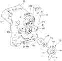
- the fixing apparatus 50 may include the fixing belt 52 having a fixed length, the pressing member 53 a disposed in the inside of the fixing belt 52 , a heat source 56 inserted into a bottom surface of the pressing member 53 a , the pressing roller 54 disposed substantially in parallel with the fixing belt 52 and configured to form a nip by pressing the fixing belt 52 and rotate the fixing belt 52 , and a temperature sensor 57 and a thermostat 58 configured to block power supply.
- the fixing belt 52 may be a cylindrical endless belt and may be typically formed of a resin film or a metal sleeve.
- the fixing belt 52 may include a base layer and a release layer covered on one surface of the base layer in a pressing roller 54 side or both surfaces of the base layer.
- an elastic layer may be disposed between the base layer and the release layer to improve image quality of a printed matter and thus a relatively wide and flat fixing nip portion may be formed.
- the base layer of the fixing belt 52 may be formed of a heat-resistant resin such as polyimide, polyamide, and polyimide amide, a metal such as stainless use steel (SUS), nickel, and copper and may have a thickness in a range of 30 to 200 ⁇ m.
- the base layer may have the thickness of 50 to 100 ⁇ m.
- the release layer covered on the surface of the base layer may be formed of a fluorine-based resin.
- the fluorine-based resin may include a copolymer of perfluoroalkoxy (PFA), polytetrafluoroethylene (PTFE), ethylene tetrafluoride, and ethylene hexafluoride, for example, fluorinated ethylene propylene (FEP) and may have a thickness of 10 to 30 ⁇ m.
- the fluorine-based resin may be mainly used as the material for the release layer and may have a thickness of 10 to 50 ⁇ m.
- the fluorine-based resin may include a copolymer of perfluoroalkoxy (PFA), polytetrafluoroethylene (PTFE), ethylene tetrafluoride, and ethylene hexafluoride, and the like.
- a tube formed of a fluorine-based resin may be used as the release layer and the release layer may be manufactured through a coating method using the fluorine-based resin.
- fluorine rubber, silicon rubber, and the like may be used as an elastic layer.
- the elastic layer may include an insulating elastic layer and the insulating elastic layer may contain one material or two or more materials of various rubber materials and various elastic materials.
- the rubber materials may include fluorine rubber, silicone rubber, natural rubber, isoprene rubber, butadiene rubber, nitrile rubber, chloroprene rubber, butyl rubber, acrylic rubber, hydrin rubber, urethane rubber, and the like.
- the elastic materials may include thermoplastic elastomers and the thermoplastic elastomers may include styrene-based, polyolefin-based, polyvinyl chloride-based, polyurethane-based, polyester-based, polyamide-based, polybutadiene-based, transpoly isoprene-based, and chlorinated polyethylene-based elastomers.
- Both ends of the fixing belt 52 may be guided by first and second bushes 56 a and 56 b detachably coupled to first and second support frames 61 and 63 in rotation.
- the pressing member 53 a may be a member which is disposed along a length direction of an inner circumferential surface of the fixing belt 52 and forms an ideal fixing nip portion between the fixing belt 52 and the pressing roller 54 by pressing the pressing roller 54 through the fixing belt 52 .
- As the pressing member 53 a a material having a good heat insulating property and having a porous structure may be used.
- a metal bracket 53 b may be disposed in an upper side of the pressing member 53 a and the heat source 56 may be inserted into the bottom surface of the pressing member 53 a .
- the pressing member 53 a and the metal bracket 53 b may be formed to substantially have a length corresponding to a length of the fixing belt.
- the metal bracket 53 b may be pressed through the first and second bushes 56 a and 56 b and may press the pressing member 53 a to the pressing roller 54 side. Both ends of the metal bracket 53 b may be supported through the first and second bushes 56 a and 56 b.
- a driving shaft 54 a which receives power from a power source disposed in the image forming apparatus 10 may be disposed in one side of the pressing member 54 and a rotation shaft 54 d may be disposed in the other side (or non-driving shaft) of the pressing roller 54 .
- the driving shaft 54 a and the rotation shaft 54 d may be indirectly rotatably supported to the first and second support frames 61 and 63 disposed in both sides of the pressing roller 54 .
- a first bearing retainer 54 b may be coupled to the first support frame 61 and a first bearing 54 c configured to support the driving shaft 54 a may be inserted into the first support frame 61 .
- a meandering adjustment member 100 may be rotatably coupled to the second support frame 63 and a second bearing (see 54 f of FIG. 5 ) configured to support the rotation shaft 54 d may be inserted into the second support frame 63 .
- the first and second bearings 54 c and 54 f may include a ring bearing or a radial bearing.
- the heat source 56 may partially heat the fixing belt 52 to be confined to the fixing nip portion of the fixing belt 52 .
- the sensor 57 may detect a temperature of the heat source 56 .
- a controller (not shown) of the image forming apparatus 10 may increase the temperature of the heat source 56 to a fixable range by supplying power to the heat source 56 in response to the temperature of the heat source 56 being reduced to the fixable range or less.
- the thermostat 58 may be disposed in the pressing member 53 a and block power supply to the heat source 56 according to a state of the fixing belt 52 .
- the thermostat 58 may have a bimetal and block the power supply to the heat source 56 in response to the temperature of the bimetal is equal to or larger than a threshold value.
- the fixing apparatus 50 may be configured to partially heat the fixing belt 52 as illustrated in FIG. 3A , but this is not limited thereto and the fixing belt 52 may be entirely heated using a halogen lamp 56 ′ as a heat source as illustrated in FIG. 3B .
- the halogen lamp 56 ′ may be disposed in a metal bracket 53 b ′ disposed in an upper side of the pressing member 53 a ′.
- a temperature sensor 57 ′ and a thermostat 58 ′ may be disposed in an outer circumferential surface of the fixing belt 52 .
- the meandering adjustment structure may include the meandering adjustment member 100 .
- the meandering adjustment member 100 may vary the position of the rotation shaft 54 d of the pressing roller 54 to a direction perpendicular to the center axis of the pressing roller.
- the meandering adjustment member 100 may move one end of the center axis (see A 2 of FIG. 2 ) of the pressing roller 54 toward a P 1 direction (see FIG. 8 ) or to a P 2 direction (see FIG. 8 ) which is a reverse direction of the P 1 direction.
- the center axis A 2 of the pressing roller 54 may be set to any one of a position in which the center axis A 2 is in parallel with the center axis (see A 1 of FIG. 2 ) of the fixing belt 52 , a position in which the center axis A 2 is inclined to the P 1 direction, and a position in which the center axis A 2 is inclined to the P 2 direction.
- the meandering adjustment member 100 may support the rotation shaft 54 d of the pressing roller 54 through the second bearing 54 f .
- the meandering adjustment member 110 may include a rotation part 110 substantially having a circular shape and a lever 130 formed to extend to a fixed length from a portion of the rotation part 110 .
- a receiving groove 111 into which the second bearing 54 f is inserted may be formed in one side of the rotation part 110 and a guide groove 113 may be formed along an outer circumferential surface of the rotation part 110 .
- the guide groove 113 may be formed so that the rotation part 110 is rotatably disposed with respect to the second support frame 63 .
- a concave portion 63 a of the second support frame 63 may be inserted into the guide groove 113 .
- the concave portion 63 a may be formed to have the same curvature as that of the guide groove 113 and thus the rotation part 110 may rotate a clockwise direction CW or a counterclockwise direction (CCW) (see FIG. 8 ).
- a stop ring 54 g may be inserted into a fixing groove 54 e of the rotation shaft 54 d so that the second bearing 54 f is not deviated from the rotation shaft 54 d.
- the lever 130 may be configured to rotate the rotation part 110 and may be formed to extend from a portion of an outer circumferential surface of the rotation part 110 .
- the length of the lever 130 may be formed in consideration of positions of a plurality of locking holes 65 a , 65 b , and 65 c formed in the second support frame 63 .
- the lever 130 may be formed to have a length so that a locking protrusion (see 131 of FIG. 6 ) formed in one lateral surface (for example, a surface facing the second support frame 63 ) of the lever 130 is selectively snap-coupled to any one of the plurality of locking holes 65 a , 65 b , and 65 c .
- the plurality of locking holes 65 a , 65 b , and 65 c may be arranged at fixed intervals along an arc concentric with the rotation center (see C 2 of FIG. 7 ) of the meandering adjustment member 100 .
- the center axis A 2 of the pressing roller 54 may be disposed in parallel with the center axis A 1 of the fixing belt 54 when the fixing apparatus 50 is viewed on a plane (in an arrow T direction illustrated in FIG. 2 ).
- a certain mark may be formed in a portion of one surface of the second support frame 63 close to the first locking hole 65 a.
- a portion of the plurality of locking holes other than the first locking hole 65 a may be a plurality of second locking holes 65 b arranged clockwise about the first locking hole 65 a and the remaining portion of the plurality of locking holes may be a plurality of third locking holes 65 c arranged counterclockwise about the first locking hole 65 a.
- the rotation center C 2 of the meandering adjustment member 100 may be arranged to be spaced at a fixed interval g from the rotation center C 1 of the pressing roller 54 .
- the rotation center C 2 of the meandering adjustment member 100 is eccentrically arranged with the rotation center C 1 of the pressing roller 54 , one end (or the rotation shaft 54 d ) of the center axis A 2 of the pressing roller 54 may be moved to the P 1 direction or the P 2 direction (see FIG. 9 ) in response to the meandering adjustment member 100 being rotated clockwise or counterclockwise.
- a distance between the center axis A 2 of the pressing roller 54 and the center axis A 1 of the fixing belt 52 in the P 1 direction may be increasingly increased so that the locking protrusion 131 is snap-coupled to the second locking hole located far away from the second locking hole nearest to the first locking hole 65 a .
- the meandering adjustment member 100 may rotate clockwise (CW) so that the locking protrusion 131 may be snap-coupled to any one of the plurality of second locking holes.
- a distance between the center axis A 2 of the pressing roller 54 and the center axis A 1 of the fixing belt 52 in the P 2 direction may be increasingly increased so that the locking protrusion 131 is snap-coupled to the third locking hole located far away from the third locking hole nearest to the first locking hole 65 a .
- the meandering adjustment member 100 may rotate counterclockwise (CCW) so that the locking protrusion 131 may be snap-coupled to any one of the plurality of third locking holes.
- the user may determine the meandering direction of the fixing belt 52 and may rotate the meandering adjustment member 100 counterclockwise in response to the fixing belt 52 being moved to a non-driving side and rotate the meandering adjustment member 100 clockwise in response to the fixing belt 52 being moved to a driving side.
- the center axis A 2 (or the rotation shaft 54 d ) of the pressing roller 54 may move to the P 1 direction in response to the meandering adjustment member 100 being rotated counterclockwise and the center axis A 2 (or the rotation shaft 54 d ) of the pressing roller 54 may move to the P 2 direction in response to the meandering adjustment member 100 being rotated clockwise.
- the user may stop the rotation of the rotation part 110 in response to the fixing belt 52 being normally running without meandering during the meandering adjustment.
- the locking protrusion 131 may be snap-coupled to any one of the plurality of locking holes 65 a , 65 b , and 65 c to fix the rotation part 110 to a fixed angle.
- the meandering adjustment of the fixing belt 52 may be first performed in a state that the locking protrusion 131 is snap-coupled to the first locking hole 65 a and the center axis A 1 of the fixing belt 52 is located in parallel with the center axis A 2 of the pressing roller 54 .
- this is not limited thereto and the meandering adjustment of the fixing belt 52 may be performed by rotating the meandering adjustment member 100 clockwise or counterclockwise in a state that the rotation part 110 is set to a fixed angle currently.
- the meandering adjustment which is performed through the meandering adjustment member 100 according to an embodiment may be performed through a direct manual operation of the meandering adjustment member 100 by the user.
- a meandering adjustment member 200 of a fixing apparatus according to another embodiment to be described below may detect the meandering of the fixing belt 52 through a sensor unit 260 and may be rotated clockwise or counterclockwise through a motor 250 driven according to a detection signal of the sensor unit 260 .
- the meandering adjustment member 200 of the fixing apparatus may vary a position of the center axis A 2 of the pressing roller 54 through an automatic method.
- a fixing apparatus including a meandering adjustment structure of a fixing belt according to another embodiment will be described with reference to FIGS. 10 and 11 .
- the same elements of a fixing apparatus 50 ′ according to another embodiment as those of the fixing apparatus 50 may be denoted by the same reference numerals and detailed description thereof will be omitted.
- the meandering adjustment structure of a fixing belt may include the meandering adjustment member 200 , the motor 250 , power transmission members 253 , 256 , and 257 , and the sensor unit 260 .
- the meandering adjustment member 200 may include a rotation part 210 into which the second bearing 54 f configured to support the rotation shaft 54 d of the pressing roller 54 is inserted and a lever 230 extending from a portion of an outer circumferential surface of the rotation part 210 .
- the rotation center of the meandering adjustment member 200 may be eccentrically arranged with the rotation center of the pressing roller 54 .
- the meandering adjustment member 200 according to another embodiment may have the same configuration as that of the meandering adjustment member 100 according to an embodiment.
- the meandering adjustment member 200 may include a gear 240 in one surface of the rotation part 210 to receive the rotation force from the motor 250 .
- the gear 240 may be separately manufactured from the rotation part 210 and may be fixed to the rotation part 210 .
- the gear 240 may be integrally manufactured with the rotation part 210 .
- the meandering adjustment member 200 may be rotated clockwise or counterclockwise through the motor 250 .
- the motor 250 may include a step motor or a servo motor which may be rotated in a forward/reverse direction.
- a worm 253 may be axially coupled to the rotation shaft 251 of the motor 250 and a worm gear 256 may be engaged with the worm 253 .
- a driven gear 257 coaxially arranged with the worm gear 256 may be coupled to a surface of the worm gear 256 which faces the second support frame 63 .
- the worm gear 256 and the driven gear 257 may be formed as a double gear so that the driven gear 257 may be simultaneously rotated with the worm gear 256 in the same rotation direction as that of the worm gear 256 .
- the worm gear 256 and the driven gear 257 may be rotatably coupled to a support shaft 258 extending from one surface of the second support frame 63 .
- the worm gear 256 may be rotatably supported to a portion (not shown) of a structure formed in the inner side of the image forming apparatus 10 .
- the driven gear 257 may be configured of the same type of gear as the gear 240 of the meandering adjustment member 200 so that the driven gear 257 is engaged with the gear 240 of the meandering adjustment member 200 .
- both the gear 240 of the meandering adjustment member 200 and the driven gear 257 may include a spur gear or a helical gear.
- the gear ratio between the gear 240 and the driven gear 257 is approximately 1:1, but this is not limited thereto and the gear ratio between the gear 240 and the driven gear 257 may have a suitable ratio according to the specification of the motor or a desired rotation speed of the motor.
- the sensor unit 260 may be disposed in a position upwardly spaced at a certain distance from a top surface of the fixing belt 52 .
- the sensor unit 260 may be fixed to an extension part (not shown) extending from one surface of the second support frame 63 .
- the sensor unit 260 may include a housing 261 fixed to the extension part of the second support frame 63 , a photosensor 263 disposed in the inner side of the housing 261 , and a terminal 265 which a signal line and a power line are in contact therewith in one side of the housing 261 .
- the photosensor 263 may include a general photosensor having a light-emitting unit (for example, light-emitting diode (LED)) and a light-receiving unit (for example, a photodiode).
- a light-emitting unit for example, light-emitting diode (LED)
- a light-receiving unit for example, a photodiode
- An identification unit 270 configured to detect the meandering of the fixing belt 52 through the photosensor 263 may be formed in one end portion of the fixing belt 52 .
- the identification unit 270 may have a different reflectance from the fixing belt 52 so that a difference between the amount of light detected through the light-receiving unit of the photosensor 263 and a preset amount of light may be caused in the meandering of the fixing belt 52 .
- the term “different reflectance” may refer to the meaning that the reflectance of the identification unit 270 is larger than that of the surface (for example, a surface of the paper-passing region) of the fixing belt 52 .
- the identification unit 270 may be formed of a thin coating layer which covers one end portion of the fixing belt 52 .
- the identification unit 270 may be formed to have a different reflectance from the surface of the fixing belt 52 by peeling off a surface of the one end portion of the fixing belt 52 .
- the signal detected through the sensor unit 260 may be transmitted to a controller (not shown) provided in the image forming apparatus 10 in response to the fixing belt 52 being moved to the non-driving side in running.
- the controller may drive the motor 250 in the forward direction and rotate the meandering adjustment member 200 counterclockwise direction. Accordingly, the center axis A 2 (or the rotation shaft 54 d ) of the pressing roller 54 may move to the P 1 direction (see FIG. 9 ) and the fixing belt 52 may move to a driving side (a side in which the driving shaft 54 a of the pressing roller is present).
- the controller may rotate the meandering adjustment member 200 clockwise by driving the motor 250 in a reverse direction in response to the movement of the fixing belt 52 being determined to be absent through the signal detected through the sensor unit 260 for a fixed time.
- the center axis A 2 (or the rotation shaft 54 d ) of the pressing roller 54 may move to the P 2 direction (see FIG. 9 ) and the fixing belt 52 may move to the driving side.
- the meandering of the fixing belt 52 may be adjusted through the meandering adjustment structure according to another embodiment through the above-described method.
- the sensor unit 260 is disposed only in the non-driving side of the fixing belt, but this is not limited thereto and the sensor unit 260 may be disposed in both-side ends of the fixing belt 52 , respectively.
- a certain pattern may be formed in the identification unit to improve the detection accuracy for the meandering of the fixing belt 52 .
- the pattern configured of a pair of solid lines 274 a and 274 b spaced at a fixed interval may be formed in an identification unit 273 .
- the pair of solid lines 274 a and 274 b may be formed along a circumferential direction of the identification unit 273 and may be formed with a color (for example, black) having a reflectance considerably smaller than that of the identification unit 273 .
- the pattern configured of a pair of dotted lines 276 a and 276 b spaced at a fixed interval may be formed in an identification unit 275 .
- the pair of dotted lines 276 a and 276 b may be formed along a circumferential direction of the identification unit 275 and may be formed with a color (for example, black) having a reflectance considerably smaller than that of the identification unit 275 .
- the pattern formed on the identification unit may be configured of three solid lines or three dotted lines.
- widths of the lines for the pattern may be different from each other and the lengths of the dots for the pattern may be different from each other.
- the patterns on the identification units 273 and 275 are formed of two solid lines or two dotted lines, but this is not limited thereto.
- the pattern may be formed in a unified form in the identification unit.
- the identification units may be formed in both end portions of the fixing belt 52 , respectively.
- the patterns having different forms from each other may be formed in the identification units, respectively and thus the sensor units configured to detect the identification units may be disposed in upper sides of both end portions of the fixing belt, respectively.
- the sensor unit 260 may include a reflective photosensor. However, this is not limited thereto and the sensor unit may detect the meandering of the fixing belt using the photosensor and an actuator detected through the photosensor.
- transmissive photosensor to distinguish the photosensor with a reflective photosensor
- actuator an example that detects the meandering of a fixing belt using a photosensor (hereinafter, referred to as ‘transmissive photosensor’ to distinguish the photosensor with a reflective photosensor) and an actuator will be described with reference to FIGS. 13 to 15 .
- a sensor unit 260 ′ may include a housing 261 ′, a transmissive photosensor 263 ′ disposed in a lower side of the housing 261 ′, a terminal 265 ′ disposed in one side of the housing 261 ′, and an actuator 266 ′ detected through the transmissive sensor 263 ′.
- the sensor unit 260 ′ may be disposed to be spaced from the fixing belt 52 near the fixing belt 52 .
- the transmissive sensor 263 ′ may include a light-emitting unit 263 a ′ and a light-receiving unit 263 b ′ disposed to be spaced at a fixed interval.
- One end 266 a ′ of the actuator 266 ′ may be disposed between the light-emitting unit 263 a ′ and the light-receiving unit 263 b ′ and the other end 266 b ′ of the actuator 266 ′ may be disposed between an edge of the fixing belt 52 and the second bush 56 b.
- the actuator 266 ′ in response to the fixing belt 52 being moved to the non-driving side according to the meandering, the actuator 266 ′ may be guided through a guide part (not shown) formed from the second support frame 63 or may be guided to a portion of an inner side of the image forming apparatus 10 so that the actuator 266 ′ may be pushed through an edge of the fixing belt 52 and the other end 266 b ′ of the actuator 266 ′ may linearly move to a second bush 56 b side.
- the pressing force applied to the actuator 266 ′ through the edge of the fixing belt 52 may be removed.
- the actuator 266 ′ may move to an edge side of the fixing belt 52 through a certain elastic member (not shown) and move the initial position.
- the elastic member may be manufactured in consideration of a length and elastic force thereof so that the actuator 266 ′ may be moved only to the initial position.
- the light-receiving unit 263 b ′ may receive the light radiated from the light-emitting unit 263 a ′.
- the sensor unit 260 ′ may transmit the detection signal to the controller.
- the controller may determine the detection signal of the sensor unit 260 ′ and rotate the meandering adjustment member 200 counterclockwise by driving the motor 250 to one direction according to a determination result. Accordingly, the center axis A 2 (or the rotation shaft 54 d ) of the pressing roller 54 may move to the P 1 direction (see FIG. 9 ).
- the pressure applied to the other end of the actuator 266 ′ through the fixing belt 52 may be released and the actuator 266 ′ may move to an initial position direction through an elastic member. Accordingly, the one end 266 a ′ of the actuator 266 ′ may be located between the light-emitting unit 263 a ′ and the light-receiving unit 263 b ′ and the light-receiving unit 263 b ′ may not receive the light radiated from the light-emitting unit 263 a′.
- the sensor unit 260 ′ may transmit the detection signal to the controller and the controller may stop the driving of the motor 250 by determining the detection signal.
- the sensor units 260 ′ may be disposed in both sides of the fixing belt 52 , respectively.
- two actuators 266 ′ may be provided to correspond to the sensor units 260 ′.
- the sensor units 260 and 260 ′ may detect the meandering of the fixing belt 52 through the photosensors 263 and 263 ′, but this is not limited thereto and the sensor unit 260 ′′ may detect the meandering of the fixing belt 52 through a height sensor 263 ′′ as illustrated in FIG. 16 .
- an identification unit 277 may be formed to have a height difference d from the fixing belt 52 .
- the identification unit 277 may be formed so that a surface of the identification unit 277 may be higher than that of the fixing belt 52 .
- the identification unit 277 may be formed so that the surface of the identification unit 277 may be lower than that of the fixing belt 52 .
- the sensor unit 260 ′′ may be disposed only in the non-driving side of the fixing part, but this is not limited thereto.
- the sensor units 260 ′′ may be located in upper sides of both end portions of the fixing belt 52 , respectively and the identification units 277 may be formed in both end portions of the fixing belt 52 , respectively.
- the controller may drive the motor 250 in the forward or reverse direction by determining the meandering of the fixing belt 52 through the height detected through the sensor unit 260 ′′ and may move the center axis A 2 (or the rotation shaft 54 d ) of the pressing roller 54 to the P 1 direction or the P 2 direction.
- the controller may stop the driving of the motor 250 in response to the detected height received from the sensor unit 260 ′′ being determined within a preset permissible range.
- the rotation center C 2 of the meandering adjustment members 100 and 200 may be eccentrically arranged with the rotation center C 1 of the pressing roller 54 and the meandering of the fixing belt 52 may be prevented by adjusting the position of the center axis A 2 (or the rotation shaft 54 d ) of the pressing roller through the clockwise/counterclockwise rotation of the meandering adjustment members 100 and 200 .
- Such a structure that varies the position of the center axis A 2 (or the rotation shaft 54 d ) of the pressing roller 54 may move the center axis A 2 (or the rotation shaft 54 d ) of the pressing roller 54 to a certain position by rotating a control screw 330 to the forward or reverse direction as illustrated in FIG. 18 .
- the gear 240 of the meandering adjustment member 200 and the double gear may be used to transmit the rotation force of the motor 250 to the meandering member 200 in the embodiment, but this is not limited thereto and the gear 240 and the driven gear 257 may be omitted in the fixing apparatus 50 ′ according to another embodiment.
- the worm gear 256 other than the gear 240 may be directly coupled to one surface of the rotation part 210 of the meandering adjustment member 200 as illustrated in FIG. 17 .
- the worm gear 256 may directly transmit the rotation force applied from the worm 253 to the rotation part 210 of the meandering adjustment member 200 .
- FIGS. 18 to 20 a fixing apparatus having a meandering adjustment structure of a fixing belt according to another embodiment will be described with reference to FIGS. 18 to 20 .
- the same elements of a fixing apparatus 50 ′′ according to another embodiment as those of the fixing apparatus 50 may be denoted by the same reference numerals and detailed description thereof will be omitted.
- the meandering adjustment structure of a fixing belt may include the meandering adjustment member 300 .
- the meandering adjustment member 300 may include a bearing holder 310 configured to support the second bearing 54 f , the control screw 330 configured to move the bearing holder 310 to the P 1 direction or the P 2 direction, and elastic members 371 and 373 configured to elastically support the bearing holder 310 to a control screw 330 side.
- a receiving groove 311 into which the second bearing 54 f is inserted may be formed in a lateral surface of the bearing holder 310 which faces the second support frame 63 . Accordingly, the bearing holder 310 may indirectly support the rotation shaft 54 d of the pressing roller 54 through the second bearing 54 f.
- a coupling hole 313 into which one end portion of the control screw 330 is inserted may be formed in a lateral surface of the bearing holder 310 which is disposed substantially perpendicular to the lateral surface in which the receiving groove 311 is formed.
- a thread part 315 may be formed in an inner circumferential surface of the coupling hole 313 .
- the control screw 330 may be rotatably coupled to a fixing part 368 formed in one lateral surface of the second support frame 63 .
- a circular protrusion 333 may be formed along an outer circumference of the control screw 330 and a guide groove 368 a into which the circular protrusion 333 is inserted may be formed in the inner side of the fixing part 368 and thus a rotation operation of the control screw 330 may be performed. Accordingly, the control screw 330 may not move to the forward/reverse direction along an axis direction of the control screw 330 and may rotate in place in the forward or reverse rotation.
- a thread part 331 may be formed in one end portion of the control screw 330 so that the control screw 330 may be screw-coupled to the coupling hole 313 of the bearing holder 310 and a cross groove 335 configured to allow the control screw 330 to be rotated using a certain tool (for example, a screw driver) may be formed in the other end portion of the control screw 330 .
- a tight line groove other than the cross groove 335 may be formed in the control screw 330 .
- the elastic members 371 and 373 may include a pair of coil springs, but this is not limited thereto and the elastic members 371 and 373 may include a single coil spring.
- the center of the coil spring may be concentrically arranged with the center of the screw control.
- One ends of the elastic members 371 and 373 may support a lateral surface of the bearing holder 310 which is located in an opposite side of the control screw 330 and the other ends of the elastic members 371 and 373 may be supported through a support rib 350 which is coupled to the second support frame 63 or is integrally formed with the second support frame 63 .
- the elastic members 371 and 373 may elastically support the bearing holder 310 so that the bearing holder 310 may move to the P 1 direction or the P 2 direction in the rotation of the control screw 330 .
- the meandering adjustment member 300 may be operated through the manual method like the meandering adjustment member 100 .
- the bearing holder 310 which is screw-coupled to the control screw 330 may linearly move to the P 1 direction in response to the control screw 330 being rotated to one direction. Accordingly, as illustrated in FIG. 22 , the center axis A 2 of the pressing roller 54 may move to the P 1 direction.
- the bearing holder 310 which is screw-coupled to the control screw 330 may linearly move to the P 2 direction in response to the control screw 330 being rotated to a reverse direction of the one direction. Accordingly, as illustrated in FIG. 24 , the center axis A 2 of the pressing roller 54 may move to the P 2 direction.
- the user may determine whether the meandering of the fixing belt 52 advances to the driving side or the non-driving side of the fixing apparatus and may adjust the meandering of the fixing belt 52 by moving the center axis (or the rotation shaft 54 d ) of the pressing roller 54 through the control screw 330 .
- the washer-shaped sub bush used between the fixing belt and the bush may be omitted and the meandering of the fixing belt may be prevented in advance.
- the fixing belt manufactured of a synthetic resin material for example, polyimide (PI)
- PI polyimide
Abstract
Description
Claims (15)
Applications Claiming Priority (3)
| Application Number | Priority Date | Filing Date | Title |
|---|---|---|---|
| KR10-2017-0089134 | 2017-07-13 | ||
| KR1020170089134A KR20190007748A (en) | 2017-07-13 | 2017-07-13 | Fusing apparatus and image forming apparatus having the same |
| PCT/KR2018/005910 WO2019013445A1 (en) | 2017-07-13 | 2018-05-24 | Fixing apparatus and image forming apparatus having the same cross-reference to related applications |
Publications (2)
| Publication Number | Publication Date |
|---|---|
| US20200142337A1 US20200142337A1 (en) | 2020-05-07 |
| US11112738B2 true US11112738B2 (en) | 2021-09-07 |
Family
ID=65001342
Family Applications (1)
| Application Number | Title | Priority Date | Filing Date |
|---|---|---|---|
| US16/629,425 Active US11112738B2 (en) | 2017-07-13 | 2018-05-24 | Fixing apparatus and image forming apparatus having the same |
Country Status (5)
| Country | Link |
|---|---|
| US (1) | US11112738B2 (en) |
| EP (1) | EP3635489B1 (en) |
| KR (1) | KR20190007748A (en) |
| CN (1) | CN110869856A (en) |
| WO (1) | WO2019013445A1 (en) |
Families Citing this family (2)
| Publication number | Priority date | Publication date | Assignee | Title |
|---|---|---|---|---|
| JP2020181159A (en) * | 2019-04-26 | 2020-11-05 | 株式会社沖データ | Fixing device and image forming apparatus |
| CN211086925U (en) | 2019-12-11 | 2020-07-24 | 珠海奔图电子有限公司 | Fixing device and image forming apparatus |
Citations (9)
| Publication number | Priority date | Publication date | Assignee | Title |
|---|---|---|---|---|
| KR19980057918U (en) | 1997-02-14 | 1998-10-26 | 김광호 | Paper Skew Correction Structure of Laser Beam Printer |
| US20060133869A1 (en) | 2004-12-10 | 2006-06-22 | Canon Kabushiki Kaisha | Image forming apparatus |
| US20080003028A1 (en) | 2006-07-03 | 2008-01-03 | Canon Kabushiki Kaisha | Belt feeding device and image heating device |
| KR20090131492A (en) | 2008-06-18 | 2009-12-29 | 삼성전자주식회사 | Image forming apparatus, fixing apparatus and belt assembly thereof |
| US20100158553A1 (en) * | 2008-12-24 | 2010-06-24 | Satoshi Ueno | Belt driving mechanism, fixing device, image forming apparatus using same, and belt position adjustment method used therein |
| US20110200343A1 (en) | 2010-02-18 | 2011-08-18 | Canon Kabushiki Kaisha | Image forming apparatus |
| US20120271447A1 (en) | 2011-04-22 | 2012-10-25 | Dongwoo Fine-Chem Co., Ltd. | Control device for preventing meandering of patterns on patterned films |
| US20140285603A1 (en) | 2013-03-19 | 2014-09-25 | Seiko Epson Corporation | Liquid ejecting apparatus and medium transport apparatus |
| US20140376978A1 (en) * | 2013-06-21 | 2014-12-25 | Samsung Electronics Co., Ltd. | Image fixing apparatus and image forming apparatus having the same |
-
2017
- 2017-07-13 KR KR1020170089134A patent/KR20190007748A/en unknown
-
2018
- 2018-05-24 CN CN201880044677.1A patent/CN110869856A/en active Pending
- 2018-05-24 WO PCT/KR2018/005910 patent/WO2019013445A1/en unknown
- 2018-05-24 EP EP18831167.4A patent/EP3635489B1/en active Active
- 2018-05-24 US US16/629,425 patent/US11112738B2/en active Active
Patent Citations (10)
| Publication number | Priority date | Publication date | Assignee | Title |
|---|---|---|---|---|
| KR19980057918U (en) | 1997-02-14 | 1998-10-26 | 김광호 | Paper Skew Correction Structure of Laser Beam Printer |
| US20060133869A1 (en) | 2004-12-10 | 2006-06-22 | Canon Kabushiki Kaisha | Image forming apparatus |
| US20080003028A1 (en) | 2006-07-03 | 2008-01-03 | Canon Kabushiki Kaisha | Belt feeding device and image heating device |
| KR20090131492A (en) | 2008-06-18 | 2009-12-29 | 삼성전자주식회사 | Image forming apparatus, fixing apparatus and belt assembly thereof |
| US20100158553A1 (en) * | 2008-12-24 | 2010-06-24 | Satoshi Ueno | Belt driving mechanism, fixing device, image forming apparatus using same, and belt position adjustment method used therein |
| US20110200343A1 (en) | 2010-02-18 | 2011-08-18 | Canon Kabushiki Kaisha | Image forming apparatus |
| US20120271447A1 (en) | 2011-04-22 | 2012-10-25 | Dongwoo Fine-Chem Co., Ltd. | Control device for preventing meandering of patterns on patterned films |
| US20140285603A1 (en) | 2013-03-19 | 2014-09-25 | Seiko Epson Corporation | Liquid ejecting apparatus and medium transport apparatus |
| US20140376978A1 (en) * | 2013-06-21 | 2014-12-25 | Samsung Electronics Co., Ltd. | Image fixing apparatus and image forming apparatus having the same |
| KR20140148230A (en) | 2013-06-21 | 2014-12-31 | 삼성전자주식회사 | Image Fixing Apparatus and Image Forming Apparatus using the same |
Also Published As
| Publication number | Publication date |
|---|---|
| EP3635489A4 (en) | 2021-01-27 |
| CN110869856A (en) | 2020-03-06 |
| EP3635489A1 (en) | 2020-04-15 |
| WO2019013445A1 (en) | 2019-01-17 |
| EP3635489B1 (en) | 2023-08-23 |
| KR20190007748A (en) | 2019-01-23 |
| US20200142337A1 (en) | 2020-05-07 |
Similar Documents
| Publication | Publication Date | Title |
|---|---|---|
| US9983526B2 (en) | Fixing device and image forming apparatus including same | |
| US8903296B2 (en) | Fixing device and image forming apparatus incorporating same | |
| US9008559B2 (en) | Fixing device with mechanism capable of heating belt effectively and image forming apparatus incorporating same | |
| US9104148B2 (en) | Image heating apparatus and image forming apparatus | |
| US8630556B2 (en) | Fixing device and image forming apparatus including same | |
| JP5640407B2 (en) | Fixing apparatus and image forming apparatus | |
| US7865120B2 (en) | Image forming apparatus with power supply for charging nip forming member and rotary fixing member | |
| KR101774893B1 (en) | Fusing device and image forming apparatus having the same | |
| US20100158553A1 (en) | Belt driving mechanism, fixing device, image forming apparatus using same, and belt position adjustment method used therein | |
| US8897688B2 (en) | Fixing device and image forming apparatus | |
| US9488942B2 (en) | Belt unit and image formation apparatus | |
| US9310735B2 (en) | Fixing device and image forming apparatus having temperature detector | |
| US20110097122A1 (en) | Fixing device, image forming apparatus | |
| US9316964B2 (en) | Fixing device and image forming apparatus | |
| US11112738B2 (en) | Fixing apparatus and image forming apparatus having the same | |
| US10120310B2 (en) | Fusing apparatus and image forming apparatus including the same | |
| US8185008B2 (en) | Fixing device and image forming apparatus with a temperature detector | |
| JP7229743B2 (en) | Fixing device | |
| JP7047633B2 (en) | Fixing device and image forming device | |
| US8929788B2 (en) | Fixing device having a fixing pad and a pressing pad and image forming apparatus incorporating the same | |
| JP2009181107A (en) | Belt twist-correcting method and device, belt device, image-forming device | |
| US20210389708A1 (en) | Fixing device and image forming appatarus including the fixing device | |
| JP2016156874A (en) | Belt control apparatus and image forming apparatus | |
| JP2008304503A (en) | Fixing device, and image forming device | |
| JPH112980A (en) | Image fixing device |
Legal Events
| Date | Code | Title | Description |
|---|---|---|---|
| FEPP | Fee payment procedure |
Free format text: ENTITY STATUS SET TO UNDISCOUNTED (ORIGINAL EVENT CODE: BIG.); ENTITY STATUS OF PATENT OWNER: LARGE ENTITY |
|
| AS | Assignment |
Owner name: HP PRINTING KOREA CO., LTD., KOREA, REPUBLIC OF Free format text: ASSIGNMENT OF ASSIGNORS INTEREST;ASSIGNORS:OH, HYUN TAEK;PARK, JIN HO;REEL/FRAME:051466/0522 Effective date: 20200108 |
|
| AS | Assignment |
Owner name: HEWLETT-PACKARD DEVELOPMENT COMPANY, L.P., TEXAS Free format text: ASSIGNMENT OF ASSIGNORS INTEREST;ASSIGNOR:HP PRINTING KOREA CO., LTD.;REEL/FRAME:051474/0078 Effective date: 20200110 |
|
| STPP | Information on status: patent application and granting procedure in general |
Free format text: NON FINAL ACTION MAILED |
|
| STPP | Information on status: patent application and granting procedure in general |
Free format text: RESPONSE TO NON-FINAL OFFICE ACTION ENTERED AND FORWARDED TO EXAMINER |
|
| STPP | Information on status: patent application and granting procedure in general |
Free format text: NOTICE OF ALLOWANCE MAILED -- APPLICATION RECEIVED IN OFFICE OF PUBLICATIONS |
|
| STPP | Information on status: patent application and granting procedure in general |
Free format text: PUBLICATIONS -- ISSUE FEE PAYMENT VERIFIED |
|
| STCF | Information on status: patent grant |
Free format text: PATENTED CASE |