US11098785B2 - Mount for vehicle - Google Patents
Mount for vehicle Download PDFInfo
- Publication number
- US11098785B2 US11098785B2 US16/454,953 US201916454953A US11098785B2 US 11098785 B2 US11098785 B2 US 11098785B2 US 201916454953 A US201916454953 A US 201916454953A US 11098785 B2 US11098785 B2 US 11098785B2
- Authority
- US
- United States
- Prior art keywords
- external ring
- housing
- mount
- stopper
- insulator
- Prior art date
- Legal status (The legal status is an assumption and is not a legal conclusion. Google has not performed a legal analysis and makes no representation as to the accuracy of the status listed.)
- Expired - Fee Related, expires
Links
Images


Classifications
-
- F—MECHANICAL ENGINEERING; LIGHTING; HEATING; WEAPONS; BLASTING
- F16—ENGINEERING ELEMENTS AND UNITS; GENERAL MEASURES FOR PRODUCING AND MAINTAINING EFFECTIVE FUNCTIONING OF MACHINES OR INSTALLATIONS; THERMAL INSULATION IN GENERAL
- F16F—SPRINGS; SHOCK-ABSORBERS; MEANS FOR DAMPING VIBRATION
- F16F13/00—Units comprising springs of the non-fluid type as well as vibration-dampers, shock-absorbers, or fluid springs
- F16F13/04—Units comprising springs of the non-fluid type as well as vibration-dampers, shock-absorbers, or fluid springs comprising both a plastics spring and a damper, e.g. a friction damper
- F16F13/06—Units comprising springs of the non-fluid type as well as vibration-dampers, shock-absorbers, or fluid springs comprising both a plastics spring and a damper, e.g. a friction damper the damper being a fluid damper, e.g. the plastics spring not forming a part of the wall of the fluid chamber of the damper
- F16F13/08—Units comprising springs of the non-fluid type as well as vibration-dampers, shock-absorbers, or fluid springs comprising both a plastics spring and a damper, e.g. a friction damper the damper being a fluid damper, e.g. the plastics spring not forming a part of the wall of the fluid chamber of the damper the plastics spring forming at least a part of the wall of the fluid chamber of the damper
- F16F13/10—Units comprising springs of the non-fluid type as well as vibration-dampers, shock-absorbers, or fluid springs comprising both a plastics spring and a damper, e.g. a friction damper the damper being a fluid damper, e.g. the plastics spring not forming a part of the wall of the fluid chamber of the damper the plastics spring forming at least a part of the wall of the fluid chamber of the damper the wall being at least in part formed by a flexible membrane or the like
- F16F13/101—Units comprising springs of the non-fluid type as well as vibration-dampers, shock-absorbers, or fluid springs comprising both a plastics spring and a damper, e.g. a friction damper the damper being a fluid damper, e.g. the plastics spring not forming a part of the wall of the fluid chamber of the damper the plastics spring forming at least a part of the wall of the fluid chamber of the damper the wall being at least in part formed by a flexible membrane or the like characterised by buffering features or stoppers
-
- F—MECHANICAL ENGINEERING; LIGHTING; HEATING; WEAPONS; BLASTING
- F16—ENGINEERING ELEMENTS AND UNITS; GENERAL MEASURES FOR PRODUCING AND MAINTAINING EFFECTIVE FUNCTIONING OF MACHINES OR INSTALLATIONS; THERMAL INSULATION IN GENERAL
- F16F—SPRINGS; SHOCK-ABSORBERS; MEANS FOR DAMPING VIBRATION
- F16F13/00—Units comprising springs of the non-fluid type as well as vibration-dampers, shock-absorbers, or fluid springs
- F16F13/04—Units comprising springs of the non-fluid type as well as vibration-dampers, shock-absorbers, or fluid springs comprising both a plastics spring and a damper, e.g. a friction damper
- F16F13/06—Units comprising springs of the non-fluid type as well as vibration-dampers, shock-absorbers, or fluid springs comprising both a plastics spring and a damper, e.g. a friction damper the damper being a fluid damper, e.g. the plastics spring not forming a part of the wall of the fluid chamber of the damper
- F16F13/08—Units comprising springs of the non-fluid type as well as vibration-dampers, shock-absorbers, or fluid springs comprising both a plastics spring and a damper, e.g. a friction damper the damper being a fluid damper, e.g. the plastics spring not forming a part of the wall of the fluid chamber of the damper the plastics spring forming at least a part of the wall of the fluid chamber of the damper
- F16F13/14—Units of the bushing type, i.e. loaded predominantly radially
- F16F13/1409—Units of the bushing type, i.e. loaded predominantly radially characterised by buffering features or stoppers
-
- B—PERFORMING OPERATIONS; TRANSPORTING
- B60—VEHICLES IN GENERAL
- B60K—ARRANGEMENT OR MOUNTING OF PROPULSION UNITS OR OF TRANSMISSIONS IN VEHICLES; ARRANGEMENT OR MOUNTING OF PLURAL DIVERSE PRIME-MOVERS IN VEHICLES; AUXILIARY DRIVES FOR VEHICLES; INSTRUMENTATION OR DASHBOARDS FOR VEHICLES; ARRANGEMENTS IN CONNECTION WITH COOLING, AIR INTAKE, GAS EXHAUST OR FUEL SUPPLY OF PROPULSION UNITS IN VEHICLES
- B60K5/00—Arrangement or mounting of internal-combustion or jet-propulsion units
- B60K5/12—Arrangement of engine supports
- B60K5/1208—Resilient supports
-
- F—MECHANICAL ENGINEERING; LIGHTING; HEATING; WEAPONS; BLASTING
- F16—ENGINEERING ELEMENTS AND UNITS; GENERAL MEASURES FOR PRODUCING AND MAINTAINING EFFECTIVE FUNCTIONING OF MACHINES OR INSTALLATIONS; THERMAL INSULATION IN GENERAL
- F16F—SPRINGS; SHOCK-ABSORBERS; MEANS FOR DAMPING VIBRATION
- F16F13/00—Units comprising springs of the non-fluid type as well as vibration-dampers, shock-absorbers, or fluid springs
- F16F13/04—Units comprising springs of the non-fluid type as well as vibration-dampers, shock-absorbers, or fluid springs comprising both a plastics spring and a damper, e.g. a friction damper
- F16F13/06—Units comprising springs of the non-fluid type as well as vibration-dampers, shock-absorbers, or fluid springs comprising both a plastics spring and a damper, e.g. a friction damper the damper being a fluid damper, e.g. the plastics spring not forming a part of the wall of the fluid chamber of the damper
- F16F13/08—Units comprising springs of the non-fluid type as well as vibration-dampers, shock-absorbers, or fluid springs comprising both a plastics spring and a damper, e.g. a friction damper the damper being a fluid damper, e.g. the plastics spring not forming a part of the wall of the fluid chamber of the damper the plastics spring forming at least a part of the wall of the fluid chamber of the damper
- F16F13/14—Units of the bushing type, i.e. loaded predominantly radially
- F16F13/1445—Units of the bushing type, i.e. loaded predominantly radially characterised by method of assembly, production or treatment
-
- B—PERFORMING OPERATIONS; TRANSPORTING
- B60—VEHICLES IN GENERAL
- B60K—ARRANGEMENT OR MOUNTING OF PROPULSION UNITS OR OF TRANSMISSIONS IN VEHICLES; ARRANGEMENT OR MOUNTING OF PLURAL DIVERSE PRIME-MOVERS IN VEHICLES; AUXILIARY DRIVES FOR VEHICLES; INSTRUMENTATION OR DASHBOARDS FOR VEHICLES; ARRANGEMENTS IN CONNECTION WITH COOLING, AIR INTAKE, GAS EXHAUST OR FUEL SUPPLY OF PROPULSION UNITS IN VEHICLES
- B60K5/00—Arrangement or mounting of internal-combustion or jet-propulsion units
- B60K5/12—Arrangement of engine supports
- B60K5/1291—Supports comprising stoppers
-
- F—MECHANICAL ENGINEERING; LIGHTING; HEATING; WEAPONS; BLASTING
- F16—ENGINEERING ELEMENTS AND UNITS; GENERAL MEASURES FOR PRODUCING AND MAINTAINING EFFECTIVE FUNCTIONING OF MACHINES OR INSTALLATIONS; THERMAL INSULATION IN GENERAL
- F16F—SPRINGS; SHOCK-ABSORBERS; MEANS FOR DAMPING VIBRATION
- F16F1/00—Springs
- F16F1/36—Springs made of rubber or other material having high internal friction, e.g. thermoplastic elastomers
- F16F1/38—Springs made of rubber or other material having high internal friction, e.g. thermoplastic elastomers with a sleeve of elastic material between a rigid outer sleeve and a rigid inner sleeve or pin, i.e. bushing-type
- F16F1/3828—End stop features or buffering
-
- F—MECHANICAL ENGINEERING; LIGHTING; HEATING; WEAPONS; BLASTING
- F16—ENGINEERING ELEMENTS AND UNITS; GENERAL MEASURES FOR PRODUCING AND MAINTAINING EFFECTIVE FUNCTIONING OF MACHINES OR INSTALLATIONS; THERMAL INSULATION IN GENERAL
- F16F—SPRINGS; SHOCK-ABSORBERS; MEANS FOR DAMPING VIBRATION
- F16F2224/00—Materials; Material properties
- F16F2224/02—Materials; Material properties solids
-
- F—MECHANICAL ENGINEERING; LIGHTING; HEATING; WEAPONS; BLASTING
- F16—ENGINEERING ELEMENTS AND UNITS; GENERAL MEASURES FOR PRODUCING AND MAINTAINING EFFECTIVE FUNCTIONING OF MACHINES OR INSTALLATIONS; THERMAL INSULATION IN GENERAL
- F16F—SPRINGS; SHOCK-ABSORBERS; MEANS FOR DAMPING VIBRATION
- F16F2230/00—Purpose; Design features
- F16F2230/0005—Attachment, e.g. to facilitate mounting onto confer adjustability
-
- F—MECHANICAL ENGINEERING; LIGHTING; HEATING; WEAPONS; BLASTING
- F16—ENGINEERING ELEMENTS AND UNITS; GENERAL MEASURES FOR PRODUCING AND MAINTAINING EFFECTIVE FUNCTIONING OF MACHINES OR INSTALLATIONS; THERMAL INSULATION IN GENERAL
- F16F—SPRINGS; SHOCK-ABSORBERS; MEANS FOR DAMPING VIBRATION
- F16F2230/00—Purpose; Design features
- F16F2230/0023—Purpose; Design features protective
Definitions
- the present invention relates to a mount for a vehicle. More particularly, the present invention relates to a mount for a vehicle, wherein a stopper is tuned and optimized more easily and variously without modifying or newly manufacturing a mold for forming an insulator.
- engine vibration of a specific frequency occurring in a specific RPM range is transmitted through a vehicle body to an internal of a vehicle, and in the instant case, the engine vibration has a considerable impact on the internal of a vehicle.
- vibration continuously occurs in the engine due to periodical changes of center positions of a piston and a connecting rod caused by upward and downward movements thereof, an inertial force caused by a reciprocating motion of a piston operating in a direction of a cylinder shaft, an inertial force caused by shaking of the connecting rod to the left and right of a crankshaft, and a periodical change of a rotational force applied to the crankshaft.
- an engine of a vehicle and the vehicle body include an engine mount provided therebetween, the engine mount supporting the engine and reducing noise and vibration transmitted from the engine.
- the engine mount supports a power train and insulates the vehicle body from being affected by a vibratory force transmitted from an engine to reduce noise and vibration, improving riding comfort.
- the engine mount is largely divided into a rubber engine mount, an air-damping engine mount, and a hydraulic engine mount.
- the rubber engine mount that is, a simple rubber mount was mostly used, but the hydraulic engine mount has been developed and used to improve a damping characteristic.
- the rubber engine mount using a rubber material is very vulnerable to a low frequency vibration (a large displacement vibration), and cannot achieve sufficient clamping performance for a high frequency vibration (a low amplitude vibration) and the low frequency vibration (the large displacement vibration).
- a hydraulic engine mount is widely used since the hydraulic engine mount can absorb and reduce a wide range of vibrations including the high frequency vibration (the low amplitude vibration) and the low frequency vibration (the large displacement vibration) input to the engine mount according to engine operation.
- the hydraulic engine mount is also referred to as “a fluid mount” or “a hydro mount”, has a structure in which a damping force occurs as fluid sealed under an insulator moves through a flow path between an upper fluid chamber and a lower fluid chamber, and may reduce the high frequency vibration (a small displacement vibration) and the low frequency vibration (the large displacement vibration) depending on situations.
- FIG. 1 is a cross-sectional view exemplarily illustrating a conventional mount for a vehicle
- FIG. 2 is a perspective view exemplarily illustrating the conventional insulator integral to a stopper of forward/rearward and leftward/rightward directions.
- the mount 10 which is shown, may be the hydraulic engine mount supporting an engine as an example of components of the power train of a vehicle, and may include a center bolt 11 engaged with an engine, an internal core 12 with which the center bolt 11 is combined, and the insulator 13 , of a rubber material formed to be integrally combined with the internal core 12 .
- the insulator 13 fixes and supports the internal core 12 , and defines an upper fluid chamber C 1 in cooperation with an orifice assembly 14 provided at a lower side of the insulator.
- a pipe 13 a is combined on a lower portion of the insulator 13 , and after the internal core 12 provided with the center bolt 11 is manufactured, the internal core 12 and the pipe 13 a are mounted in the mold, and then the insulator 13 of a rubber material combined integrally with the internal core 12 and the pipe 13 a may be formed through a vulcanizing process in the mold.
- the orifice assembly 14 may include an orifice plate 15 and may further include a membrane 16 .
- the orifice plate 15 is transversely provided to divide a mount internal fluid chamber into the upper fluid chamber C 1 and a lower fluid chamber C 2 at a lower side of the insulator 13 in the mount 10 .
- the orifice plate 15 may include an upper plate 15 a and a lower plate 15 b.
- the orifice plate 15 has an orifice 15 c forming a circular bypass flow path (also referred to as an inertia track) to induce fluid movement between the upper fluid chamber C 1 and the lower fluid chamber C 2 .
- a diaphragm 17 is provided at a lower side of the orifice plate 15 , and the orifice plate 15 and the diaphragm 17 define the lower fluid chamber C 2 .
- the orifice plate 15 may include a hole communicating the orifice 15 c with the upper fluid chamber C 1 and a hole communicating the orifice 15 c with the lower fluid chamber C 2 .
- the upper fluid chamber C 1 , the orifice 15 c , and the lower fluid chamber C 2 are configured to communicate with one another such that fluid moves therebetween through the holes of the orifice plate 15 .
- the insulator 13 having three-direction characteristics, of the mount 10 for a vehicle is configured to be integrally provided with the stopper 13 b of forward/rearward and leftward/rightward directions, and according to required characteristics of the mount, the shape of the stopper 13 b is required to be variously tuned for a secondary characteristic in the insulator 13 .
- FIG. 2 illustrates two kinds of insulators 13 integral to the stoppers, each of which has a different-shaped stopper 13 b , and a left-side insulator and a right-side insulator are insulators integral to the stoppers.
- the shape of the stopper 13 b is tuned to be optimized in keeping with a required mount characteristic, and the shape of the stopper 13 b may be variously modified when necessary.
- the stopper 13 b is integrally provided with the insulator 13 , a mold for forming the insulator is required to be modified whenever the shape of the stopper is tuned, and accordingly, the degree of tuning freedom is reduced by the modification of the stopper, which has many restrictions.
- the power train i.e., an engine and a transmission, which contributes to vehicle vibration the most during starting and stopping a vehicle, may be designed to be integrally provided with the vehicle body.
- the shape of the stopper is also required to be different for every power train. This is because inertial specification and a rotation shaft are different for every power train.
- the stopper cannot be applied to the conventional upside down mount.
- FIG. 3 is a cross-sectional view exemplarily illustrating a portion of configuration of a housing 18 and the insulator 13 in the conventional upside down mount, and as for the upside down mount, the mount is provided upside down, wherein a rubber system including the insulator 13 is positioned at a lower side of the mount and a fluid system including the orifice assembly and the diaphragm is positioned at an upper side of the mount.
- the insulator 13 is vulcanizingly formed to be integral to the housing 18 , and when the insulator 13 is formed to be integral to the housing 18 , due to the structure of removing the insulator mold, forming the stopper of forward and rearward directions to be integral to the insulator is impossible.
- Various aspects of the present invention are directed to providing a mount for a vehicle, wherein the shape of a stopper is tuned and optimized more easily and variously without modifying or newly manufacturing a mold for forming an insulator.
- a mount for supporting a power train in the vehicle including: a stopper assembly combined on an internal surface of a housing to be disposed in an annular shape along the vicinity of the outsides of insulators combined with the housing, wherein the stopper assembly may include: an external ring of an annular shape combined on the internal surface of the housing; and stopper members fixed on an internal surface of the external ring to be positioned along the vicinity of the outsides of the insulators, each of the stopper members being spaced from each other to be in contact with an internal insulator of the insulators.
- the mount for a vehicle has a structure in which a stopper of forward/rearward and leftward/rightward directions is independently manufactured and assembled, whereby the shape of the stopper is easily and freely tuned and optimized without modifying an insulator mold.
- the degree of tuning freedom of the stopper increases, and other various problems of the conventional insulator integral to the stopper, such as increased cost, an increased development period, and increased expenses due to mold modification and the increase of the number of the mold, are removed.
- the insulator and the stopper which are manufactured independently, are combined with each other, whereby optimization is achieved to improve an optimization rate and performance of the mount, and to reduce the period and expenses required for development.
- an upside down mount to which the stopper is applied is easily manufactured.
- FIG. 1 is a cross-sectional view exemplarily illustrating a conventional mount for a vehicle
- FIG. 2 is a perspective view exemplarily illustrating a conventional insulator integral to a stopper
- FIG. 3 is a cross-sectional view exemplarily illustrating a portion of configuration of a housing and the insulator in the conventional upside down mount;
- FIG. 4 is a cross-sectional view exemplarily illustrating a mount according to the exemplary embodiment of the present invention.
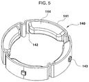
- FIG. 5 is a perspective view exemplarily illustrating a stopper assembly of the mount according to the exemplary embodiment of the present invention
- FIG. 6 is a top plan view exemplarily illustrating the stopper assembly of the mount according to the exemplary embodiment of the present invention.
- FIG. 7 is a perspective view exemplarily illustrating a process in which the stopper assembly is assembled with the housing in the mount according to the exemplary embodiment of the present invention
- FIG. 8 is a top plan view of a state of the stopper assembly assembled with the housing in the mount according to the exemplary embodiment of the present invention.
- FIG. 9 is a perspective view exemplarily illustrating a process in which a fluid system is assembled with the housing of the mount according to the exemplary embodiment of the present invention.
- FIG. 10 is a perspective view exemplarily illustrating an assembling process of the fluid system of the mount according to the exemplary embodiment of the present invention.
- FIG. 11 is a perspective view exemplarily illustrating a process in which a rubber system of the mount according to the exemplary embodiment of the present invention is assembled.
- FIG. 12 is a perspective view exemplarily illustrating a mount according to various exemplary embodiments of the present invention.
- the present invention is directed to providing a mount for a vehicle, wherein the shape of a stopper is tuned and optimized more easily and variously for a secondary characteristic without modifying or newly manufacturing a mold for forming insulators.
- the present invention is directed to providing the mount for a vehicle, wherein degree of tuning freedom of the stopper is increased, the expense and cost of the mold are reduced, and the period and expenses required for development are decreased.
- the stopper is independently manufactured in a shape tuned and optimized to meet required characteristics of the stopper and is assembled with a housing.
- the mount of the present invention as a mount for the power train may be embodied as an engine mount or as an upside down mount to which the stopper is applied.
- FIG. 4 is a cross-sectional view exemplarily illustrating a mount according to the exemplary embodiment of the present invention
- FIG. 5 is a perspective view exemplarily illustrating a stopper assembly of the mount according to the exemplary embodiment of the present invention
- FIG. 6 is a top plan view exemplarily illustrating the stopper assembly of the mount according to the exemplary embodiment of the present invention.
- FIG. 7 is a perspective view exemplarily illustrating a process in which the stopper assembly is assembled with the housing in the mount according to the exemplary embodiment of the present invention.
- FIG. 8 is a top plan view of a state of the stopper assembly assembled with the housing in the mount according to the exemplary embodiment of the present invention.
- the mount 100 of the shown embodiment as a fluid-sealed upside down mount is a tunable upside down engine mount configured such that a rubber system 103 having an insulator 130 and a fluid-sealed fluid system 104 are separated from each other.
- the rubber system 103 and the fluid system 104 are assembled with each other to form the integral type mount 100 .
- the upside down mount 100 includes the rubber system 103 including the insulator 130 positioned on a lower side of the mount, and the fluid-sealed fluid system 104 positioned on an upper side of the mount, the fluid system including an orifice assembly 170 and a diaphragm 180 .
- a support bracket 102 provided integrally with the housing 101 is mounted to an engine as an example of the power train, which is not shown, and an additional lower support bracket 111 is mounted to the vehicle body, which is not shown, while the under support bracket is combined with a center bolt 110 .
- the support bracket 102 mounted to the side of the engine is provided integrally with the housing 101 .
- the rubber system 103 may include the center bolt 110 mounted to the side of the vehicle body, an internal core 120 with which the center bolt 110 is combined, and the first insulator 130 formed to be integrally combined with the internal core 120 .
- the first insulator 130 supports the internal core 120 and the center bolt 110 while the first insulator is integrally combined with the housing 101 .
- the first insulator 130 is vulcanizingly formed to be integrally combined with an internal surface of the housing 101 such that the first insulator 130 surrounds the internal core 120 in the mold after the housing 101 and the internal core 120 is disposed in the mold.
- the stopper assembly 140 is combined on the internal surface of the housing 101 to be disposed at an outside of the first insulator 130 along the vicinity of the first insulator, wherein the stopper assembly 140 combined on the internal surface of the housing 101 is spaced from the internal first insulator 130 of the insulators.
- the stopper assembly 140 is disposed to have an annular shape along the vicinity of the first insulator 130 while being combined on the internal surface of the housing 101 , and as shown in FIGS. 5, 6, and 8 , the stopper assembly may be disposed to have a circular annular shape along the vicinity of the first insulator 130 .
- the fluid system 104 provided above the stopper assembly 140 is inserted into an upper portion of the housing 101 to be combined thereon.
- the fluid system 104 includes a cupped hook 150 , the orifice assembly 170 assembled in the cupped hook 150 , the diaphragm 180 , and a second insulator 160 hooked to the cupped hook 150 by hooking.
- the cupped hook 150 may be manufactured of synthetic resin, and includes a plurality of hooks 151 mounted on a lower end portion thereof, the hooks being disposed at predetermined intervals along a circumferential direction of the cupped hook.
- the second insulator 160 is positioned on an upper side of the first insulator 130 to be supported by the first insulator 130 of the rubber system 103 .
- each of the hooks 151 of the cupped hook 150 is hooked to and combined with a holding jaw 162 of a core pipe 161 of an annular shape combined integrally on an external surface of the second insulator 160 , whereby the cupped hook 150 , the second insulator 160 , the orifice assembly 170 , and the diaphragm 180 , which form the fluid system 104 , are integrated with each other.
- the second insulator 160 defines the upper fluid chamber C 1 in cooperation with the orifice assembly 170 of an upper side of the second insulator.
- the orifice assembly 170 includes an orifice plate 171 and a membrane 175 , wherein the orifice plate 171 is transversely provided to divide an internal fluid chamber of the fluid-sealed fluid system into the upper fluid chamber C 1 and the lower fluid chamber C 2 between the second insulator 160 and the diaphragm 180 .
- the orifice plate 171 may include an upper plate 172 and a lower plate 173 .
- the orifice plate 171 has an orifice 174 defining a circular bypass flow path (also referred to as an inertia track) to induce fluid movement between the upper fluid chamber C 1 and the lower fluid chamber C 2 .
- a circular bypass flow path also referred to as an inertia track
- the diaphragm 180 is provided at an upper side of the orifice plate 171 , and accordingly, the orifice plate 171 and the diaphragm 180 define the lower fluid chamber C 2 .
- the orifice plate 171 includes a hole communicating the orifice 174 with the upper fluid chamber C 1 and a hole communicating the orifice 174 with the lower fluid chamber C 2 .
- the upper fluid chamber C 1 , the orifice 174 , and the lower fluid chamber C 2 are communicating with each other such that fluid moves between the upper fluid chamber C 1 , the orifice 174 , and the lower fluid chamber C 2 through the holes of the orifice plate 171 .
- the stopper assembly 140 which is independently manufactured and configured, may be tuned according to a required characteristic of the mount, and as shown in FIG. 5 and FIG. 6 , the stopper assembly 140 includes an external ring 141 combined with the housing 101 to be in close contact with the internal surface of the housing 101 , and stopper members 144 fixed to an internal surface of the external ring.
- the external ring 141 may have an annular shape, and be manufactured of synthetic resin.
- the external ring 141 includes bending portions 142 provided thereon, the bending portions being disposed at predetermined intervals along a circumferential direction of the external ring and being transformable elastically.
- Each of the bending portions 142 of the external ring 141 is a portion restored to an initial state in a shape by the elasticity thereof after the bending portion is transformed.
- the bending portions 142 have shapes bent to protrude from the external ring 141 to the internal side thereof, and may be provided to be disposed at predetermined intervals along the circumferential surface of the external ring 141 thereon.
- the bending portions 142 are configured to divide an entire section of the external ring being along the circumferential direction of the external ring 141 into various sections of predetermined lengths, and each of the stopper members 144 is integrally fixed on the internal circumferential surface located between two neighboring bending portions 142 on the external ring 141 .
- the external ring 141 includes a total of four bending portions 142 disposed at predetermined intervals along a circumferential direction of the external ring thereon, and each of the stopper members 144 of rubber materials is mounted on the internal circumferential surface of the external ring between the two neighboring bending portions 142 and accordingly, a total of four stopper members 144 are disposed.
- the bending portions 142 of the external ring 141 may be contracted in a radial direction of the external ring while being bent such that a diameter of the external ring is reduced, and in the present contracted state, the external ring 141 is press-fitted into the housing 101 to be provided therein.
- the shape of the bending portions 142 transformed during the contraction is restored to an initial shape of the bending portion while the bending portion is spread by an elasticity thereof, so that the external ring 141 is expanded or extended.
- an elastic restoring force of the bending portions 142 operates in a direction increasing the diameter of the external ring 141 .
- the external ring 141 is press-fitted into the housing 101 , the external ring is brought into close contact with the internal surface of the housing 101 by the elastic restoring force of the bending portions 142 , that is, by a force expanding or extending in the radial direction thereof, and accordingly, the external ring 141 may be prevented from being removed from the housing 101 .
- the external ring 141 includes fitting protrusions 143 mounted on an surface of an external side thereof and the housing 101 , to which the external ring 141 in fitted, includes insertion holes 105 to which the fitting protrusions 143 are inserted.
- the fitting protrusions 143 and the insertion holes 105 allow the combined state of the stopper assembly 140 with the housing 101 to be maintained such that the stopper assembly 140 is securely fixed on the internal surface of the housing 101 , so that the stopper assembly 140 is prevented from deviating from the housing 101 .
- the external ring 141 when the stopper assembly 140 is combined with the housing, the external ring 141 is contracted in the radial direction thereof, and as shown in FIG. 7 , is press-fitted into the housing 101 , and then when the fitting protrusions 143 of the external ring 141 are inserted into the insertion holes 105 of the housing 101 , the external ring 141 may be completely locked to the housing 101 so as not to be removed from the housing.
- the external ring 141 may include a total of four bending portions 142 , and in the instant case, as shown in FIGS. 5, 6, and 8 , the bending portions 142 are provided to be diagonally positioned on the external ring 141 .
- each of the stopper members 144 is disposed on the internal circumferential surface of the external ring 141 positioned between the two neighboring bending portions 142 .
- a total of four stopper members 144 may be provided.
- each pair of the stopper members 144 mounted on the internal circumferential surface of the external ring 141 surfaces each other.
- each of two stopper members 144 is provided at a front side and a rear side, respectively, relative to the forward and rearward directions of the vehicle to face each other, and each of the remaining two stopper members 144 is provided at a left side and a right side, respectively, to face each other.
- two stopper members 144 face each other by being disposed forward and rearward thereof, and the remaining two stopper members 144 face each other by being disposed leftward and rightward.
- the entirety of the stopper members 144 forming the stopper assembly 140 is circularly disposed on the internal circumferential surface of the external ring 141 , and the circular stopper assembly 140 is circularly disposed around the first insulator 130 relative to the first insulator 130 while the circular stopper assembly is fixed on the internal surface of the housing 101 of the mount 100 .
- the power train such as an engine may move in forward and rearward directions or in leftward and rightward directions in an engine chamber, the power train does not move diagonally.
- the stopper members 144 are disposed forward/rearward and leftward/rightward while surrounding the first insulator 130 , and the bending portions 142 are diagonally disposed.
- the bending portions 142 and the first insulator 130 do not contact with each other and only the stopper members 144 of rubber materials may contact with the external circumferential surface of the first insulator 130 .
- the fluid system 104 which is completely assembled, is combined on an upper side of the housing 101 .
- FIG. 9 illustrates a process in which the fluid system 104 is assembled with the housing 101 .
- a plurality of locking protrusions 152 is mounted on an external circumferential surface of the cupped hook 150 , and a plurality of guide grooves 106 long vertically is mounted on the internal surface of the housing 101 such that the locking protrusions 152 are inserted into the guide groove to be guided.
- locking holes 107 into which the locking protrusions 152 of the cupped hook 150 are inserted, is formed through a side portion of a lower end portion of the guide grooves 106 .
- the plurality of locking protrusions 152 may be mounted on the cupped hook 150 to be disposed at predetermined intervals along the circumferential direction of the cupped hook 150
- the plurality of guide grooves 106 and locking holes 107 may be mounted on the housing 101 to be disposed at predetermined intervals along a circumferential direction of the housing 101 .
- a handle 153 mounted on the cupped hook 150 by protruding therefrom is held and when the entirety of the fluid system 104 including the cupped hook 150 is rotated, the locking protrusions 152 of the cupped hook 150 are inserted into the locking holes 107 of the housing 101 , the cupped hook is locked to the housing, and finally, the fluid system 104 is completely engaged with and fixed to the housing 101 .
- FIG. 10 is a perspective view exemplarily illustrating an assembling process of the fluid system, and shows a process of the diaphragm 180 , the orifice lower plate 173 , the membrane 175 , the orifice upper plate 172 , and the second insulator 160 assembled sequentially in the cupped hook 150 , which includes synthetic resin, forming the fluid system 104 .
- the second insulator 160 is finally inserted into the cupped hook 150 to be laminated on the orifice upper plate 172 .
- the core pipe 161 which may be made of a metal material such as an aluminum alloy, is integrally combined with the second insulator 160 , and after the second insulator 160 is inserted into the cupped hook 150 , the second insulator 160 is compressed such that the core pipe 161 of the second insulator 160 is hooked by the hooks 151 of the cupped hook 150 .
- the hooks 151 of the cupped hook 150 are hooked to an end portion of the core pipe 161 ; the second insulator 160 is integrally fixed to the cupped hook 150 ; and finally, all the components of the fluid system 104 including the cupped hook 150 are integrally assembled with each other after the hooking.
- fluid is injected into the fluid system 104 in a dry filling method.
- FIG. 10 shows the exemplary embodiment of the hooks 151 of the cupped hook 150 hooked to the end portion of the core pipe 161 , and the end portion of the core pipe 161 is the holding jaw hooked by the hooks 151 .
- the hooks 151 of the cupped hook 150 may be hooked to the holding jaw 162 , and a process of the exemplary embodiment of FIG. 4 being assembled is the same as the above process.
- FIG. 11 shows an assembling process of the rubber system 103 , and after the housing 101 and the internal core 120 with which the center bolt 110 is combined are provided in a vulcanized mold to form the first insulator 130 , the first insulator 130 is vulcanizingly formed in the mold, whereby the housing 101 , the first insulator 130 , and the internal core 120 are integrated with each other.
- FIG. 12 is a perspective view exemplarily illustrating a mount according to various exemplary embodiments of the present invention, and shows a mount 100 in which a rubber system 103 , which is a normal type and not an upside down type, is positioned on an upper side of the mount and a fluid system 104 is positioned on a lower side thereof.
- a rubber system 103 which is a normal type and not an upside down type
- a stopper assembly 140 of the same configuration is assembled on an internal surface of a housing 101 , and furthermore, the stopper assembly 140 is circularly disposed along the vicinity of an insulator 130 a in the housing 101 .
- the mount 100 according to an exemplary embodiment of the present invention features the stopper assembly 140 , which is independently manufactured and provided.
Landscapes
- Engineering & Computer Science (AREA)
- General Engineering & Computer Science (AREA)
- Mechanical Engineering (AREA)
- Chemical & Material Sciences (AREA)
- Combustion & Propulsion (AREA)
- Transportation (AREA)
- Manufacturing & Machinery (AREA)
- Arrangement Or Mounting Of Propulsion Units For Vehicles (AREA)
- Combined Devices Of Dampers And Springs (AREA)
Abstract
Description
Claims (8)
Applications Claiming Priority (2)
| Application Number | Priority Date | Filing Date | Title |
|---|---|---|---|
| KR1020190027468A KR102703267B1 (en) | 2019-03-11 | 2019-03-11 | Mount for vehicle |
| KR10-2019-0027468 | 2019-03-11 |
Publications (2)
| Publication Number | Publication Date |
|---|---|
| US20200292026A1 US20200292026A1 (en) | 2020-09-17 |
| US11098785B2 true US11098785B2 (en) | 2021-08-24 |
Family
ID=72423011
Family Applications (1)
| Application Number | Title | Priority Date | Filing Date |
|---|---|---|---|
| US16/454,953 Expired - Fee Related US11098785B2 (en) | 2019-03-11 | 2019-06-27 | Mount for vehicle |
Country Status (3)
| Country | Link |
|---|---|
| US (1) | US11098785B2 (en) |
| KR (1) | KR102703267B1 (en) |
| CN (1) | CN111674252B (en) |
Families Citing this family (2)
| Publication number | Priority date | Publication date | Assignee | Title |
|---|---|---|---|---|
| FR3068649B1 (en) * | 2017-07-10 | 2021-11-26 | Renault Sas | MONOBLOC SUPPORT DEVICE FOR A POWERTRAIN UNIT INTEGRATING A RELAY BEARING |
| FR3122907B1 (en) * | 2021-05-17 | 2023-04-14 | Sumitomo Riko Co Ltd | elastic joint |
Citations (8)
| Publication number | Priority date | Publication date | Assignee | Title |
|---|---|---|---|---|
| JP2009299782A (en) | 2008-06-12 | 2009-12-24 | Honda Motor Co Ltd | Engine mount |
| US20090321202A1 (en) * | 2008-06-30 | 2009-12-31 | Tokai Rubber Industries, Ltd. | Power unit support structure |
| JP4823976B2 (en) | 2007-06-25 | 2011-11-24 | 倉敷化工株式会社 | Liquid filled anti-vibration support device |
| JP2013204801A (en) | 2012-03-29 | 2013-10-07 | Tokai Rubber Ind Ltd | Cylindrical antivibration device, and method for manufacturing the same |
| US20130264756A1 (en) * | 2012-04-06 | 2013-10-10 | Tokai Rubber Industries, Ltd. | Fluid filled vibration damping device |
| KR101324533B1 (en) | 2012-09-10 | 2013-11-08 | 기아자동차주식회사 | Hydro engine mount |
| US20150069685A1 (en) * | 2013-09-06 | 2015-03-12 | Hyundai Motor Company | Structure of motor-mount for electric vehicle |
| US10808793B2 (en) * | 2018-08-23 | 2020-10-20 | Hyundai Motor Company | Hydraulic transmission mount and method of manufacturing the same |
Family Cites Families (8)
| Publication number | Priority date | Publication date | Assignee | Title |
|---|---|---|---|---|
| JPS4823976B1 (en) * | 1969-11-04 | 1973-07-18 | ||
| KR0174047B1 (en) * | 1994-10-04 | 1999-02-18 | 전성원 | Hydraulic engine mount |
| JP3740907B2 (en) * | 1999-09-06 | 2006-02-01 | 東海ゴム工業株式会社 | Fluid filled vibration isolator |
| JP3819009B2 (en) * | 2004-05-24 | 2006-09-06 | 倉敷化工株式会社 | Engine mount structure |
| CN104589989B (en) * | 2014-12-26 | 2017-01-25 | 宁波拓普集团股份有限公司 | Automobile power assembly hanging device |
| KR102258470B1 (en) * | 2015-03-20 | 2021-05-31 | 현대자동차주식회사 | Structure of engine mount |
| KR101823904B1 (en) * | 2016-07-05 | 2018-01-31 | 현대자동차주식회사 | Stoper for transmission-mount |
| US9945512B2 (en) * | 2016-09-09 | 2018-04-17 | Hyundai Motor Company | Structure for mounting engine mount |
-
2019
- 2019-03-11 KR KR1020190027468A patent/KR102703267B1/en active Active
- 2019-06-27 US US16/454,953 patent/US11098785B2/en not_active Expired - Fee Related
- 2019-07-08 CN CN201910609496.5A patent/CN111674252B/en active Active
Patent Citations (8)
| Publication number | Priority date | Publication date | Assignee | Title |
|---|---|---|---|---|
| JP4823976B2 (en) | 2007-06-25 | 2011-11-24 | 倉敷化工株式会社 | Liquid filled anti-vibration support device |
| JP2009299782A (en) | 2008-06-12 | 2009-12-24 | Honda Motor Co Ltd | Engine mount |
| US20090321202A1 (en) * | 2008-06-30 | 2009-12-31 | Tokai Rubber Industries, Ltd. | Power unit support structure |
| JP2013204801A (en) | 2012-03-29 | 2013-10-07 | Tokai Rubber Ind Ltd | Cylindrical antivibration device, and method for manufacturing the same |
| US20130264756A1 (en) * | 2012-04-06 | 2013-10-10 | Tokai Rubber Industries, Ltd. | Fluid filled vibration damping device |
| KR101324533B1 (en) | 2012-09-10 | 2013-11-08 | 기아자동차주식회사 | Hydro engine mount |
| US20150069685A1 (en) * | 2013-09-06 | 2015-03-12 | Hyundai Motor Company | Structure of motor-mount for electric vehicle |
| US10808793B2 (en) * | 2018-08-23 | 2020-10-20 | Hyundai Motor Company | Hydraulic transmission mount and method of manufacturing the same |
Non-Patent Citations (1)
| Title |
|---|
| Translation of KR 101324533 document obtained from website: https://worldwide.espacenet.com on Feb. 3, 2021. * |
Also Published As
| Publication number | Publication date |
|---|---|
| US20200292026A1 (en) | 2020-09-17 |
| KR102703267B1 (en) | 2024-09-04 |
| KR20200108612A (en) | 2020-09-21 |
| CN111674252A (en) | 2020-09-18 |
| CN111674252B (en) | 2025-03-14 |
Similar Documents
| Publication | Publication Date | Title |
|---|---|---|
| US10611227B2 (en) | Mount assembly for vehicle | |
| JP6532367B2 (en) | Tubular vibration control with bracket | |
| US11028894B2 (en) | Tubular vibration-damping device | |
| US11098785B2 (en) | Mount for vehicle | |
| KR101362461B1 (en) | Mount for vehicle | |
| US10507715B1 (en) | Mount assembly for vehicle | |
| JP4716387B2 (en) | Anti-vibration bush | |
| JP2001280386A (en) | Cylindrical mount | |
| KR102258470B1 (en) | Structure of engine mount | |
| US11292306B2 (en) | Hydraulic mount for vehicles | |
| JP2009180330A (en) | Automobile cylindrical vibration absorbing device manufacturing method | |
| JP7079784B2 (en) | Cylindrical motor mount for electric vehicles | |
| JP2004232824A (en) | Strut mount | |
| JP6898273B2 (en) | Liquid-filled anti-vibration device | |
| JP2018062978A (en) | Vibration isolator | |
| JP4081421B2 (en) | Anti-vibration mount assembly | |
| WO2024185329A1 (en) | Cylindrical anti-vibration device for motor mount | |
| JP7527258B2 (en) | Multiple types of cylindrical vibration isolation devices with brackets | |
| JP3932025B2 (en) | Anti-vibration bush | |
| KR101687694B1 (en) | Double insulation hydro mount | |
| KR102283774B1 (en) | Pre-load type mount | |
| KR20230126526A (en) | Press-fit type motor mounting double insulated bush structure | |
| US20260016066A1 (en) | Tubular vibration-damping device for motor mount | |
| JPH07269632A (en) | Strut mount | |
| JP2007263148A (en) | Member mount and its manufacturing method |
Legal Events
| Date | Code | Title | Description |
|---|---|---|---|
| AS | Assignment |
Owner name: KIA MOTORS CORPORATION, KOREA, REPUBLIC OF Free format text: ASSIGNMENT OF ASSIGNORS INTEREST;ASSIGNOR:KIM, SEUNG WON;REEL/FRAME:049616/0016 Effective date: 20190617 Owner name: HYUNDAI MOTOR COMPANY, KOREA, REPUBLIC OF Free format text: ASSIGNMENT OF ASSIGNORS INTEREST;ASSIGNOR:KIM, SEUNG WON;REEL/FRAME:049616/0016 Effective date: 20190617 |
|
| FEPP | Fee payment procedure |
Free format text: ENTITY STATUS SET TO UNDISCOUNTED (ORIGINAL EVENT CODE: BIG.); ENTITY STATUS OF PATENT OWNER: LARGE ENTITY |
|
| STPP | Information on status: patent application and granting procedure in general |
Free format text: NON FINAL ACTION MAILED |
|
| STPP | Information on status: patent application and granting procedure in general |
Free format text: RESPONSE TO NON-FINAL OFFICE ACTION ENTERED AND FORWARDED TO EXAMINER |
|
| STPP | Information on status: patent application and granting procedure in general |
Free format text: NOTICE OF ALLOWANCE MAILED -- APPLICATION RECEIVED IN OFFICE OF PUBLICATIONS |
|
| STCF | Information on status: patent grant |
Free format text: PATENTED CASE |
|
| FEPP | Fee payment procedure |
Free format text: MAINTENANCE FEE REMINDER MAILED (ORIGINAL EVENT CODE: REM.); ENTITY STATUS OF PATENT OWNER: LARGE ENTITY |
|
| LAPS | Lapse for failure to pay maintenance fees |
Free format text: PATENT EXPIRED FOR FAILURE TO PAY MAINTENANCE FEES (ORIGINAL EVENT CODE: EXP.); ENTITY STATUS OF PATENT OWNER: LARGE ENTITY |
|
| STCH | Information on status: patent discontinuation |
Free format text: PATENT EXPIRED DUE TO NONPAYMENT OF MAINTENANCE FEES UNDER 37 CFR 1.362 |
|
| FP | Lapsed due to failure to pay maintenance fee |
Effective date: 20250824 |