US10808793B2 - Hydraulic transmission mount and method of manufacturing the same - Google Patents
Hydraulic transmission mount and method of manufacturing the same Download PDFInfo
- Publication number
- US10808793B2 US10808793B2 US16/169,896 US201816169896A US10808793B2 US 10808793 B2 US10808793 B2 US 10808793B2 US 201816169896 A US201816169896 A US 201816169896A US 10808793 B2 US10808793 B2 US 10808793B2
- Authority
- US
- United States
- Prior art keywords
- core
- spoke
- hydraulic transmission
- stoppers
- transmission mount
- Prior art date
- Legal status (The legal status is an assumption and is not a legal conclusion. Google has not performed a legal analysis and makes no representation as to the accuracy of the status listed.)
- Active, expires
Links
- 230000005540 biological transmission Effects 0.000 title claims abstract description 71
- 238000004519 manufacturing process Methods 0.000 title claims description 11
- 239000007788 liquid Substances 0.000 claims abstract description 50
- 238000003780 insertion Methods 0.000 claims abstract description 34
- 230000037431 insertion Effects 0.000 claims abstract description 34
- 239000012530 fluid Substances 0.000 claims abstract description 27
- 230000008878 coupling Effects 0.000 claims description 28
- 238000010168 coupling process Methods 0.000 claims description 28
- 238000005859 coupling reaction Methods 0.000 claims description 28
- 229910000831 Steel Inorganic materials 0.000 claims description 22
- 239000010959 steel Substances 0.000 claims description 22
- 230000033001 locomotion Effects 0.000 claims description 10
- 238000004512 die casting Methods 0.000 claims description 9
- 238000000034 method Methods 0.000 claims description 9
- 239000012212 insulator Substances 0.000 description 13
- 239000000463 material Substances 0.000 description 12
- 230000001133 acceleration Effects 0.000 description 9
- 229910052751 metal Inorganic materials 0.000 description 5
- 239000002184 metal Substances 0.000 description 5
- XEEYBQQBJWHFJM-UHFFFAOYSA-N Iron Chemical compound [Fe] XEEYBQQBJWHFJM-UHFFFAOYSA-N 0.000 description 4
- 229910052782 aluminium Inorganic materials 0.000 description 4
- XAGFODPZIPBFFR-UHFFFAOYSA-N aluminium Chemical compound [Al] XAGFODPZIPBFFR-UHFFFAOYSA-N 0.000 description 4
- 230000000694 effects Effects 0.000 description 4
- 238000002955 isolation Methods 0.000 description 4
- 238000005516 engineering process Methods 0.000 description 3
- 238000012986 modification Methods 0.000 description 3
- 230000004048 modification Effects 0.000 description 3
- 238000005266 casting Methods 0.000 description 2
- 238000007710 freezing Methods 0.000 description 2
- 229910052742 iron Inorganic materials 0.000 description 2
- 230000002159 abnormal effect Effects 0.000 description 1
- 230000003247 decreasing effect Effects 0.000 description 1
- 238000004880 explosion Methods 0.000 description 1
- 239000012528 membrane Substances 0.000 description 1
- 238000005058 metal casting Methods 0.000 description 1
- 229920003002 synthetic resin Polymers 0.000 description 1
- 239000000057 synthetic resin Substances 0.000 description 1
Images


Classifications
-
- F—MECHANICAL ENGINEERING; LIGHTING; HEATING; WEAPONS; BLASTING
- F16—ENGINEERING ELEMENTS AND UNITS; GENERAL MEASURES FOR PRODUCING AND MAINTAINING EFFECTIVE FUNCTIONING OF MACHINES OR INSTALLATIONS; THERMAL INSULATION IN GENERAL
- F16F—SPRINGS; SHOCK-ABSORBERS; MEANS FOR DAMPING VIBRATION
- F16F13/00—Units comprising springs of the non-fluid type as well as vibration-dampers, shock-absorbers, or fluid springs
- F16F13/04—Units comprising springs of the non-fluid type as well as vibration-dampers, shock-absorbers, or fluid springs comprising both a plastics spring and a damper, e.g. a friction damper
- F16F13/06—Units comprising springs of the non-fluid type as well as vibration-dampers, shock-absorbers, or fluid springs comprising both a plastics spring and a damper, e.g. a friction damper the damper being a fluid damper, e.g. the plastics spring not forming a part of the wall of the fluid chamber of the damper
- F16F13/08—Units comprising springs of the non-fluid type as well as vibration-dampers, shock-absorbers, or fluid springs comprising both a plastics spring and a damper, e.g. a friction damper the damper being a fluid damper, e.g. the plastics spring not forming a part of the wall of the fluid chamber of the damper the plastics spring forming at least a part of the wall of the fluid chamber of the damper
- F16F13/14—Units of the bushing type, i.e. loaded predominantly radially
- F16F13/16—Units of the bushing type, i.e. loaded predominantly radially specially adapted for receiving axial loads
-
- B—PERFORMING OPERATIONS; TRANSPORTING
- B60—VEHICLES IN GENERAL
- B60K—ARRANGEMENT OR MOUNTING OF PROPULSION UNITS OR OF TRANSMISSIONS IN VEHICLES; ARRANGEMENT OR MOUNTING OF PLURAL DIVERSE PRIME-MOVERS IN VEHICLES; AUXILIARY DRIVES FOR VEHICLES; INSTRUMENTATION OR DASHBOARDS FOR VEHICLES; ARRANGEMENTS IN CONNECTION WITH COOLING, AIR INTAKE, GAS EXHAUST OR FUEL SUPPLY OF PROPULSION UNITS IN VEHICLES
- B60K5/00—Arrangement or mounting of internal-combustion or jet-propulsion units
- B60K5/12—Arrangement of engine supports
- B60K5/1291—Supports comprising stoppers
-
- F—MECHANICAL ENGINEERING; LIGHTING; HEATING; WEAPONS; BLASTING
- F16—ENGINEERING ELEMENTS AND UNITS; GENERAL MEASURES FOR PRODUCING AND MAINTAINING EFFECTIVE FUNCTIONING OF MACHINES OR INSTALLATIONS; THERMAL INSULATION IN GENERAL
- F16F—SPRINGS; SHOCK-ABSORBERS; MEANS FOR DAMPING VIBRATION
- F16F13/00—Units comprising springs of the non-fluid type as well as vibration-dampers, shock-absorbers, or fluid springs
- F16F13/04—Units comprising springs of the non-fluid type as well as vibration-dampers, shock-absorbers, or fluid springs comprising both a plastics spring and a damper, e.g. a friction damper
- F16F13/06—Units comprising springs of the non-fluid type as well as vibration-dampers, shock-absorbers, or fluid springs comprising both a plastics spring and a damper, e.g. a friction damper the damper being a fluid damper, e.g. the plastics spring not forming a part of the wall of the fluid chamber of the damper
- F16F13/08—Units comprising springs of the non-fluid type as well as vibration-dampers, shock-absorbers, or fluid springs comprising both a plastics spring and a damper, e.g. a friction damper the damper being a fluid damper, e.g. the plastics spring not forming a part of the wall of the fluid chamber of the damper the plastics spring forming at least a part of the wall of the fluid chamber of the damper
- F16F13/10—Units comprising springs of the non-fluid type as well as vibration-dampers, shock-absorbers, or fluid springs comprising both a plastics spring and a damper, e.g. a friction damper the damper being a fluid damper, e.g. the plastics spring not forming a part of the wall of the fluid chamber of the damper the plastics spring forming at least a part of the wall of the fluid chamber of the damper the wall being at least in part formed by a flexible membrane or the like
- F16F13/101—Units comprising springs of the non-fluid type as well as vibration-dampers, shock-absorbers, or fluid springs comprising both a plastics spring and a damper, e.g. a friction damper the damper being a fluid damper, e.g. the plastics spring not forming a part of the wall of the fluid chamber of the damper the plastics spring forming at least a part of the wall of the fluid chamber of the damper the wall being at least in part formed by a flexible membrane or the like characterised by buffering features or stoppers
-
- F—MECHANICAL ENGINEERING; LIGHTING; HEATING; WEAPONS; BLASTING
- F16—ENGINEERING ELEMENTS AND UNITS; GENERAL MEASURES FOR PRODUCING AND MAINTAINING EFFECTIVE FUNCTIONING OF MACHINES OR INSTALLATIONS; THERMAL INSULATION IN GENERAL
- F16F—SPRINGS; SHOCK-ABSORBERS; MEANS FOR DAMPING VIBRATION
- F16F13/00—Units comprising springs of the non-fluid type as well as vibration-dampers, shock-absorbers, or fluid springs
- F16F13/04—Units comprising springs of the non-fluid type as well as vibration-dampers, shock-absorbers, or fluid springs comprising both a plastics spring and a damper, e.g. a friction damper
- F16F13/06—Units comprising springs of the non-fluid type as well as vibration-dampers, shock-absorbers, or fluid springs comprising both a plastics spring and a damper, e.g. a friction damper the damper being a fluid damper, e.g. the plastics spring not forming a part of the wall of the fluid chamber of the damper
- F16F13/08—Units comprising springs of the non-fluid type as well as vibration-dampers, shock-absorbers, or fluid springs comprising both a plastics spring and a damper, e.g. a friction damper the damper being a fluid damper, e.g. the plastics spring not forming a part of the wall of the fluid chamber of the damper the plastics spring forming at least a part of the wall of the fluid chamber of the damper
- F16F13/10—Units comprising springs of the non-fluid type as well as vibration-dampers, shock-absorbers, or fluid springs comprising both a plastics spring and a damper, e.g. a friction damper the damper being a fluid damper, e.g. the plastics spring not forming a part of the wall of the fluid chamber of the damper the plastics spring forming at least a part of the wall of the fluid chamber of the damper the wall being at least in part formed by a flexible membrane or the like
- F16F13/103—Units comprising springs of the non-fluid type as well as vibration-dampers, shock-absorbers, or fluid springs comprising both a plastics spring and a damper, e.g. a friction damper the damper being a fluid damper, e.g. the plastics spring not forming a part of the wall of the fluid chamber of the damper the plastics spring forming at least a part of the wall of the fluid chamber of the damper the wall being at least in part formed by a flexible membrane or the like characterised by method of assembly, production or treatment
-
- F—MECHANICAL ENGINEERING; LIGHTING; HEATING; WEAPONS; BLASTING
- F16—ENGINEERING ELEMENTS AND UNITS; GENERAL MEASURES FOR PRODUCING AND MAINTAINING EFFECTIVE FUNCTIONING OF MACHINES OR INSTALLATIONS; THERMAL INSULATION IN GENERAL
- F16F—SPRINGS; SHOCK-ABSORBERS; MEANS FOR DAMPING VIBRATION
- F16F13/00—Units comprising springs of the non-fluid type as well as vibration-dampers, shock-absorbers, or fluid springs
- F16F13/04—Units comprising springs of the non-fluid type as well as vibration-dampers, shock-absorbers, or fluid springs comprising both a plastics spring and a damper, e.g. a friction damper
- F16F13/06—Units comprising springs of the non-fluid type as well as vibration-dampers, shock-absorbers, or fluid springs comprising both a plastics spring and a damper, e.g. a friction damper the damper being a fluid damper, e.g. the plastics spring not forming a part of the wall of the fluid chamber of the damper
- F16F13/08—Units comprising springs of the non-fluid type as well as vibration-dampers, shock-absorbers, or fluid springs comprising both a plastics spring and a damper, e.g. a friction damper the damper being a fluid damper, e.g. the plastics spring not forming a part of the wall of the fluid chamber of the damper the plastics spring forming at least a part of the wall of the fluid chamber of the damper
- F16F13/14—Units of the bushing type, i.e. loaded predominantly radially
- F16F13/1463—Units of the bushing type, i.e. loaded predominantly radially characterised by features of passages between working chambers
-
- F—MECHANICAL ENGINEERING; LIGHTING; HEATING; WEAPONS; BLASTING
- F16—ENGINEERING ELEMENTS AND UNITS; GENERAL MEASURES FOR PRODUCING AND MAINTAINING EFFECTIVE FUNCTIONING OF MACHINES OR INSTALLATIONS; THERMAL INSULATION IN GENERAL
- F16F—SPRINGS; SHOCK-ABSORBERS; MEANS FOR DAMPING VIBRATION
- F16F15/00—Suppression of vibrations in systems; Means or arrangements for avoiding or reducing out-of-balance forces, e.g. due to motion
- F16F15/02—Suppression of vibrations of non-rotating, e.g. reciprocating systems; Suppression of vibrations of rotating systems by use of members not moving with the rotating systems
- F16F15/023—Suppression of vibrations of non-rotating, e.g. reciprocating systems; Suppression of vibrations of rotating systems by use of members not moving with the rotating systems using fluid means
-
- B—PERFORMING OPERATIONS; TRANSPORTING
- B60—VEHICLES IN GENERAL
- B60Y—INDEXING SCHEME RELATING TO ASPECTS CROSS-CUTTING VEHICLE TECHNOLOGY
- B60Y2306/00—Other features of vehicle sub-units
- B60Y2306/09—Reducing noise
-
- F—MECHANICAL ENGINEERING; LIGHTING; HEATING; WEAPONS; BLASTING
- F16—ENGINEERING ELEMENTS AND UNITS; GENERAL MEASURES FOR PRODUCING AND MAINTAINING EFFECTIVE FUNCTIONING OF MACHINES OR INSTALLATIONS; THERMAL INSULATION IN GENERAL
- F16F—SPRINGS; SHOCK-ABSORBERS; MEANS FOR DAMPING VIBRATION
- F16F2226/00—Manufacturing; Treatments
- F16F2226/04—Assembly or fixing methods; methods to form or fashion parts
-
- F—MECHANICAL ENGINEERING; LIGHTING; HEATING; WEAPONS; BLASTING
- F16—ENGINEERING ELEMENTS AND UNITS; GENERAL MEASURES FOR PRODUCING AND MAINTAINING EFFECTIVE FUNCTIONING OF MACHINES OR INSTALLATIONS; THERMAL INSULATION IN GENERAL
- F16H—GEARING
- F16H57/00—General details of gearing
- F16H57/02—Gearboxes; Mounting gearing therein
- F16H57/028—Gearboxes; Mounting gearing therein characterised by means for reducing vibration or noise
Definitions
- the present invention relates to a hydraulic transmission mount, which isolates vibration and noise of an engine of a vehicle, and a method of manufacturing the same, and particularly, to a hydraulic transmission mount, which utilizes a flow of a fluid to provide an operation mode suitable for a situation in which a vehicle accelerates, and a method of manufacturing the same.
- engine vibration which occurs within a particular RPM region when a vehicle travels, has a particular frequency and is transmitted to an internal of a vehicle through a vehicle body, and an explosion component in an engine dominantly affects the internal of the vehicle.
- a transmission of the vehicle refers to a device which transmits power from the engine to driving wheels while changing rotational force and a speed so that the rotational force and the speed are suitable for a traveling state of the vehicle, and the transmission is directly connected to a crank shaft in the engine through a clutch.
- a large amount of vibration and a large amount of noise occur due to influences of a mechanical operation of the transmission and an operation of the engine.
- a transmission mount is used when mounting the transmission on the vehicle body to improve noise, vibration & harshness (NVH) performance and ride quality of an occupant in the vehicle by minimizing transmission of vibration and noise generated from the engine and the transmission.
- NASH vibration & harshness
- Korean Patent Application Laid-Open No. 10-2013-0000874 (Breaking Type Tm Mount Bracket For Improving Crashworthiness) in the related art relates to a transmission mount mounted on a transmission of a vehicle and discloses a structure of a transmission mount which improves a collision performance by ensuring a sufficient deformation section of a vehicle body by fracturing a front bracket by use of a fracturable transmission mount bracket at the time of a vehicle collision, and improves a collision performance by dispersing collision energy by allowing a front bracket body having a wedge shape to rotate the transmission mount bracket.
- the technology in the related art has a problem in that an effect of isolating vibration deteriorates because an insulator is only made of rubber such that properties of the mount are rapidly changed at the time of sudden unintended acceleration of the vehicle or at the time of a vehicle collision.
- Korean Patent Application Laid-Open No. 10-2013-0055112 (Hydraulic Transmission Mount) in the related art relates to a hydraulic transmission mount and discloses a structure of a hydraulic transmission mount in which liquid chambers filled with a fluid are provided in an insulator, and the fluid flows between the liquid chambers, such that an effect of isolating vibration is improved.
- the technology in the related art has a problem in that a gap between the insulator and a bracket is not maintained due to deformation in the insulator, and thus the insulator collides with the bracket again, which causes impact exerted on a vehicle.
- FIG. 1 illustrates a structure of a transmission mount in the related art.
- a mount 100 includes an insulator 120 which is made of a rubber material and surrounds an internal core 130 , and a mounting bracket 110 which surrounds the insulator 120 and fixes the mount 100 to a vehicle body.
- a liquid chamber unit 122 which is filled with a fluid, is positioned at a lower side of the insulator 120 , and vibration or noise of a vehicle is reduced as the fluid flows.
- the structure of the transmission mount in the related art has a problem in that a vibration isolation performance deteriorates because the insulator 120 only made of rubber is rapidly deformed due to inertial force and force required to isolate vibration is rapidly changed when impact is exerted on the vehicle in front and rear directions or the vehicle suddenly and unintentionally accelerates or rapidly brakes.
- a gap at one side between the insulator 120 and the mounting bracket 110 is decreased due to deformation of the insulator 120 , and in the instant case, a gap at the other side is increased to the contrary.
- the increased gap rather causes the insulator 120 to exert large impact on the mounting bracket 110 through a long stroke, and as a result, there is a problem in that the mount 100 cannot sufficiently isolate vibration and the vehicle is not strong against impact.
- Various aspects of the present invention are directed to providing a hydraulic transmission mount which improves a vibration and noise isolation performance of a vehicle at the time of a collision or sudden unintended acceleration of the vehicle by maintaining a gap between a bracket for fixing a mount on a vehicle body and an insulator disposed in the bracket in a transmission mount in the related art, and a method of manufacturing the same.
- a hydraulic transmission mount which isolates noise or vibration of an engine
- the hydraulic transmission mount including: a core which moves horizontally together with a main rubber vulcanized outside the core in accordance with behavior of a vehicle; stoppers which are coupled to both surfaces of the core and define a hermetic liquid chamber with the core; a bracket which surrounds the stoppers and fixes the hydraulic transmission mount to a vehicle body; and a spoke which penetrates an insertion hole formed at a center of the core and has protruding regions that are bent at both end portions of the spoke and in contact with the stoppers, in which a fluid encapsulated in the liquid chamber flows through the insertion hole in accordance with the behavior of the vehicle.
- the stoppers may be deformed by the movement of the core that occurs in accordance with the behavior of the vehicle.
- Multiple coupling protrusions may be formed on both surfaces of the core.
- the hydraulic transmission mount may further include steel plates which have coupling holes to be coupled to the coupling protrusions and are coupled between the core and the stoppers.
- the spoke may maintain a horizontal gap between the bracket and the stoppers.
- the spoke may have a predetermined length to prevent the core from being withdrawn from the bracket.
- Various aspects of the present invention are directed to providing a method of manufacturing a hydraulic transmission mount that isolates noise or vibration of an engine, the method including: a first step of die-casting a core that moves horizontally in accordance with behavior of a vehicle; a second step of vulcanizing a main rubber so that the main rubber surrounds the core; a third step of inserting and assembling a divided spoke into an insertion hole formed at a center of the core; and a fourth step of forming a hermetic liquid chamber in stoppers by coupling the stoppers and the core in a liquid.
- the third step may include coupling and assembling one portion of the spoke formed with an assembling protrusion and the other portion of the spoke formed with an assembling groove.
- the method may further include coupling steel plates to the core after the third step.
- the method may further include coupling a floor plate to the main rubber and press-fitting the main rubber into a bracket after the fourth step.
- a vibration isolation performance is maximized when a vehicle slowly accelerates, and a performance of controlling behavior of a power train is maximized when the vehicle rapidly accelerates, such that there is an advantage in that an operation mode may vary in accordance with a situation in which the vehicle accelerates.
- the present invention is advantageous in that since a flow path is formed in the mount, a performance of isolating vibration generated from the engine of the vehicle is excellent.
- the present invention is advantageous in that a collision performance of the vehicle may be improved by preventing withdrawal of the mount at the time of a vehicle collision.
- FIG. 1 illustrates a structure of a transmission mount in the related art.
- FIG. 2 illustrates a structure of a hydraulic transmission mount of the present invention.
- FIG. 3 illustrates a core of the present invention.
- FIG. 4A illustrates a steel plate of the present invention.
- FIG. 4B illustrates a state in which the steel plate of the present invention is coupled to a stopper.
- FIG. 5A illustrates an appearance of the hydraulic transmission mount of the present invention when a vehicle is stopped.
- FIG. 5B illustrates an appearance of the hydraulic transmission mount of the present invention when the vehicle suddenly and unintentionally accelerates.
- FIG. 5C illustrates an appearance of the hydraulic transmission mount of the present invention when the vehicle rapidly brakes.
- FIG. 6A illustrates behavior of a liquid in a liquid chamber of the present invention when the vehicle slowly accelerates.
- FIG. 6B illustrates behavior of the liquid in the liquid chamber of the present invention when the vehicle rapidly accelerates.
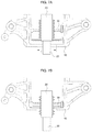
- FIG. 7A illustrates a state in which a spoke of the present invention is coupled to the core when viewed from the top side thereof.
- FIG. 7B illustrates a state in which the spoke of the present invention prevents the core from being withdrawn from a bracket at the time of a collision of the vehicle.
- FIG. 8 illustrates a flowchart of a method of manufacturing the hydraulic transmission mount of the present invention.
- FIG. 9 illustrates a state in which a main rubber is vulcanized outside the core of the present invention.
- FIG. 10A illustrates a state in which the spoke is inserted into an insertion hole of the present invention.
- FIG. 10B illustrates a state in which the spoke of the present invention is inserted and assembled into the insertion hole.
- FIG. 11 illustrates a state in which the stopper and the steel plate of the present invention are coupled to the core.
- FIG. 12A and FIG. 12B illustrate a state in which a floor plate is coupled to the main rubber of the present invention.
- FIG. 13 illustrates a state in which the main rubber to which the floor plate of the present invention is coupled is press-fitted into the bracket.
- FIG. 2 illustrates a structure of a hydraulic transmission mount 1 of the present invention.
- the core 20 is connected to a transmission and is configured to support the transmission, and the core 20 may be moved horizontally in accordance with behavior of the vehicle.
- Metal such as aluminum may be used as a material of the core 20 so that the core 20 is easily coupled to a vehicle body, but the material of the core 20 is not limited thereto.
- a main rubber 50 which is an elastic body made of a rubber material, may be vulcanized outside the core 20 to surround the core 20 to isolate vibration of the vehicle.
- Stopper 40 are coupled to both surfaces of the core 20 having the vulcanized main rubber 50 , and a hermetic liquid chamber 41 may be formed between the stopper 40 and the core 20 .
- the stopper 40 is made of an elastic body such as rubber to isolate vibration of the vehicle and may be deformed in accordance with the behavior of the vehicle or the movement of the core 20 .
- a fluid encapsulated in an internal space of the stopper 40 flows from one side stopper 40 to the other side stopper 40 in accordance with the behavior of the vehicle, and vibration of the vehicle may be isolated by frictional force generated by resistance of the fluid generated during the flow of the fluid.
- An anti-freezing liquid may be used as the fluid in the liquid chamber 41 to prevent the fluid from being frozen when an atmospheric temperature outside the vehicle is low and to prevent the engine and accessory devices in the vehicle from being overheated, but the fluid is not limited to the anti-freezing liquid.
- a bracket 10 may surround the stoppers 40 and the main rubber 50 to fix the hydraulic transmission mount 1 to the vehicle body.
- a spoke 30 which has a thin bar shape and penetrates an insertion hole 23 formed at a center of the core 20 , is coupled at the center of the core 20 , and protruding regions are bent at both end portions of the spoke 30 and may be in contact with both sides in the stoppers 40 .
- the protruding regions each may have a vertical length greater than a diameter of the insertion hole 23 so that the spoke 30 is not withdrawn from the insertion hole 23 even though the core 20 moves.
- a material of the spoke 30 may be metal so that the spoke 30 is not easily deformed by the behavior of the vehicle or the movement of the core 20 , and synthetic resin may be used to reduce weight of the components, but the material of the spoke 30 is not limited thereto.
- the core 20 moves horizontally along the spoke 30 , and the fluid encapsulated in the liquid chamber 41 may flow to the other side stopper 40 through the insertion hole 23 .
- the stoppers 40 include a first stopper 410 and a second stopper 420
- the hermetic liquid chambers 41 include a first hermetic liquid chamber 412 enclosed by the core 20 and the first stopper 410 and a second hermetic liquid chamber 414 enclosed by the core 20 and the second stopper 420 .
- the first hermetic liquid chamber 412 and the second hermetic liquid chamber 414 fluidically-communicate with each other through the insertion hole 23 .
- the spoke 30 is mounted through the insertion hole 23 , a first end of the spoke 30 is connected to the first stopper 410 and a second end of the spoke 30 is connected to the second stopper 420 .
- FIG. 3 illustrates the core 20 of the present invention.
- multiple coupling protrusions 21 may be formed on both surfaces of the core 20 so that the core 20 is coupled to the stoppers 40 .
- the insertion hole 23 is formed at the center of the core 20 , the spoke 30 is penetratively coupled to the insertion hole 23 , and the insertion hole 23 may define a flow path through which the fluid in the stoppers 40 may flow.
- FIG. 4A and FIG. 4B illustrate steel plates 60 of the present invention.
- coupling holes 61 which are coupled to the coupling protrusions 21 , may be formed in the steel plates 60 .
- a material of the steel plate 60 may be metal such as iron or aluminum so that the coupling holes 61 may be coupled to the coupling protrusions 21 by riveting, but the material of the steel plate 60 is not limited thereto.
- a cross section of the steel plate 60 has the same shape as a cross section of the stopper 40 , and the steel plate 60 is formed to be smaller than the stopper 40 , such that the steel plate 60 may be fitted into the stopper 40 without a gap.
- the stopper 40 made of an elastic body such as rubber may define a rubber membrane at an edge portion of the steel plate 60 .
- the steel plate 60 which is fitted with the edge portion in the stopper 40 , may be coupled between the core 20 and the stopper 40 as the coupling holes 61 are coupled to the coupling protrusions 21 .
- FIG. 5A illustrates an appearance of the hydraulic transmission mount 1 of the present invention when the vehicle is stopped.
- the stoppers 40 may be coupled to the core 20 while maintaining a horizontal gap between the bracket 10 and the stoppers 40 .
- FIG. 5B illustrates the behavior of the hydraulic transmission mount 1 of the present invention when the vehicle suddenly and unintentionally accelerates.
- the core 20 is moved along the spoke 30 by inertial force in a direction opposite to the acceleration direction of the vehicle, such that the stoppers 40 and the main rubber 50 connected to the core 20 may be deformed.
- the one side stopper 40 is extended, and the other side stopper 40 is compressed, but a horizontal length of the spoke 30 in the stoppers 40 is maintained because the material of the spoke 40 is not deformed in accordance with the behavior of the vehicle, such that the deformation of the stoppers 40 , which surround the spoke 30 , is restricted.
- the spoke 30 maintains a horizontal gap between the bracket 10 and the stopper 40 so that the gap is similar to the gap when the vehicle is stopped.
- FIG. 5C illustrates the behavior of the hydraulic transmission mount 1 of the present invention when the vehicle rapidly brakes.
- the core 20 is moved along the spoke 30 by inertial force in a direction in which the vehicle travels, and the stoppers 40 and the main rubber 50 connected to the core 20 may be deformed.
- the one side stopper 40 is extended, and the other side stopper 40 is compressed, but the horizontal length of the spoke 30 in the stoppers 40 is maintained because the material of the spoke 40 is not deformed in accordance with the behavior of the vehicle, such that the deformation of the stoppers 40 , which surround the spoke 30 , is also restricted.
- the spoke 30 maintains the horizontal gap between the bracket 10 and the stopper 40 so that the gap is similar to the gap when the vehicle is stopped.
- the spoke 30 prevents the horizontal gap between the bracket 10 and the stopper 40 from being greatly changed, preventing the stoppers 40 from colliding again with the other side of the bracket 10 through a long stroke after colliding with one side of the bracket 10 .
- FIG. 6A illustrates behavior of the liquid in the liquid chamber 41 of the present invention when the vehicle slowly accelerates.
- the arrow in FIG. 6A illustrates a flow of the fluid. Referring to FIG. 6A , when the vehicle softly starts moving or slowly brakes at a low speed, the fluid in the liquid chamber 41 flows slowly.
- FIG. 6B illustrates behavior of the liquid in the liquid chamber 41 of the present invention when the vehicle rapidly accelerates.
- the arrow in FIG. 6B illustrates a flow of the fluid. Referring to 6 B, when the vehicle rapidly starts moving or rapidly brakes, the fluid in the liquid chamber 41 flows very fast.
- torque generated from the engine enables a tire to move fast, and the tire transmits high torque to the ground surface, facilitating a sports mode that allows the driver to feel high acceleration.
- a flow speed of the fluid varies in accordance with an acceleration situation of the vehicle, and an operation mode may vary by use of the situation in which resistance of the fluid varies in accordance with the variation of the flow speed of the fluid.
- FIG. 7A illustrates a state in which the spoke 30 in an exemplary embodiment of the present invention is coupled to the core 20 when viewed from the top side thereof.
- the spoke 30 penetrates the core 20 , and a connecting portion 25 is coupled to the transmission and enters or exits from a core entrance 1 in accordance with the motion of the transmission.
- FIG. 7B illustrates a state in which the spoke 30 in an exemplary embodiment of the present invention prevents the core 20 from being withdrawn from the bracket 10 at the time of a vehicle collision.
- the core 20 coupled to the transmission moves together with the transmission in the movement direction of the transmission.
- a collision performance of the vehicle may greatly deteriorate.
- the spoke 30 may have a predetermined length greater than a width of the core entrance 1 formed in the bracket 10 so that the spoke 30 resists the bracket 10 when the core 20 moves.
- the spoke 30 prevents the core 20 from being withdrawn from the bracket 10 , and the stopper 40 , the main rubber 50 , and the like, which are coupled to the core 20 , are not withdrawn from the bracket 10 , such that a collision performance of the vehicle may be improved.
- FIG. 8 illustrates a flowchart of a method of manufacturing the hydraulic transmission mount 1 of the present invention.
- the method of manufacturing the hydraulic transmission mount 1 may include: a first step S 10 of die-casting the core 20 which is configured to move horizontally in accordance with the behavior of the vehicle; a second step S 20 of vulcanizing the main rubber 50 so that the main rubber 50 surrounds the core 20 ; a third step S 30 of inserting and assembling the divided spoke 30 into the insertion hole 23 formed at a center of the core 20 ; and a fourth step S 40 of forming the hermetic liquid chamber 41 in the stoppers 40 by coupling the stopper 40 and the core 20 in the liquid.
- FIG. 9 illustrates a state in which the main rubber 50 is vulcanized outside the core 20 of the present invention.
- the core 20 may be manufactured by die-casting an aluminum material.
- the die casting is also called metal casting and refers to a precise casting method that obtains a casted product identical in shape to a mold by injecting molten metal into the mold made of steel which is accurately machined to have a shape perfectly coincident with a required casting shape.
- the die casting manufactures a product with an accurate dimension and thus has an advantage in that it is not necessary to finish the product, and the die casting enables mass production because the die casting manufactures products with excellent mechanical properties.
- a mold may be manufactured so that the coupling protrusions 21 are formed on both surfaces of the core 20 and the insertion hole 23 is formed at the center of the core 20 .
- FIG. 10A and FIG. 10B illustrate a state in which the spoke 30 is inserted into the insertion hole 23 of the present invention.
- the divided parts of the spoke 30 may be inserted into the insertion hole 23 of the core 20 in opposite directions from both sides of the core 20 and then coupled to each other.
- One portion of the spoke 30 which is inserted into the insertion hole 23 from one side of the insertion hole 23 , may have an assembling protrusion 31 at one end portion directed toward the insertion hole 23
- the other portion of the spoke 30 which is inserted into the insertion hole 23 from the other side of the insertion hole 23 , may have an assembling groove 33 at one end portion directed toward the insertion hole 23 .
- the assembling protrusion 31 and the assembling groove 33 are assembled, and the spoke 30 is inserted into the insertion hole 23 , such that the core 20 may support the spoke 30 .
- the core 20 moves along the spoke 30 .
- an external surface of the spoke 30 may be coated with rubber with a thickness of about 0.5 mm to prevent abnormal noise caused by friction with the core 20 .
- FIG. 11 illustrates a state in which the stoppers 40 and the steel plates 60 in an exemplary embodiment of the present invention are coupled to the core 20 .
- the cross section of the steel plate 60 has the same shape as the cross section of the stopper 40 , and the cross section of the steel plate 60 is smaller than the cross section of the stopper 40 , such that the steel plate 60 may be fitted into the stopper 40 without a gap.
- the coupling holes 61 of the steel plate 60 are matched with the coupling protrusions 21 of the core 20 in a state in which the core 20 is submerged in the liquid, and the coupling holes 61 and the coupling protrusions 21 are fastened with rivets.
- the stoppers 40 are coupled to both surfaces of the core 20 , such that the liquid may be encapsulated in the hermetic space in the stopper 40 .
- FIG. 12A and FIG. 12B illustrate a state in which a floor plate 70 is coupled to the main rubber 50 of the present invention.
- the floor plate 70 mounted in the bracket 10 may be coupled to a lower end portion of the main rubber 50 so that the fluid is encapsulated between the main rubber 50 and the floor plate 70 .
- the floor plate 70 and the main rubber 50 define the lower liquid chamber 41 and a lower liquid chamber 71 enclosed by bridges 80 of the main rubber 50 which are connected to a lower portion of the core 20 .
- the bridges 80 of the main rubber 50 include a first bridge 810 and a second bridge 820 connected to the floor plate 70 and the lower liquid chamber 41 is formed by the first bridge 810 , the second bridge 820 and the floor plate 70 .
- the floor plate 70 and a bottom plate 85 are spaced with a gap. Accordingly, vibration of the vehicle may be isolated and impact may be reduced by frictional force of the fluid in the liquid chambers 71 and 41 .
- FIG. 13 illustrates a state in which the main rubber 50 to which the floor plate 70 in an exemplary embodiment of the present invention is coupled is press-fitted into the bracket 10 .
- a material of the bracket 10 is metal such as iron or aluminum, and the hydraulic transmission mount 1 may be fixed to the vehicle body by the bracket 10 .
Abstract
Description
Claims (15)
Applications Claiming Priority (2)
| Application Number | Priority Date | Filing Date | Title |
|---|---|---|---|
| KR1020180098841A KR102625545B1 (en) | 2018-08-23 | 2018-08-23 | Hydraulic transmission mount and method for manufacturing the same |
| KR10-2018-0098841 | 2018-08-23 |
Publications (2)
| Publication Number | Publication Date |
|---|---|
| US20200063823A1 US20200063823A1 (en) | 2020-02-27 |
| US10808793B2 true US10808793B2 (en) | 2020-10-20 |
Family
ID=69584456
Family Applications (1)
| Application Number | Title | Priority Date | Filing Date |
|---|---|---|---|
| US16/169,896 Active 2039-04-20 US10808793B2 (en) | 2018-08-23 | 2018-10-24 | Hydraulic transmission mount and method of manufacturing the same |
Country Status (2)
| Country | Link |
|---|---|
| US (1) | US10808793B2 (en) |
| KR (1) | KR102625545B1 (en) |
Cited By (1)
| Publication number | Priority date | Publication date | Assignee | Title |
|---|---|---|---|---|
| US11098785B2 (en) * | 2019-03-11 | 2021-08-24 | Hyundai Motor Company | Mount for vehicle |
Citations (13)
| Publication number | Priority date | Publication date | Assignee | Title |
|---|---|---|---|---|
| US4673169A (en) * | 1984-09-12 | 1987-06-16 | Continental Gummi-Werke Aktiengesellschaft | Elastic motor mount |
| JPS62205859A (en) | 1986-03-07 | 1987-09-10 | Nissan Motor Co Ltd | Body mounting device for vehicle |
| US5263815A (en) * | 1990-12-24 | 1993-11-23 | Boge Ag | Engine mounting for motor vehicles |
| KR19980050213A (en) | 1996-12-20 | 1998-09-15 | 박병재 | Stopper integrated engine mounting |
| KR19980061232A (en) | 1996-12-31 | 1998-10-07 | 박병재 | Front and rear vibration suppression engine mount |
| KR19980061233A (en) | 1996-12-31 | 1998-10-07 | 박병재 | Front and rear vibration suppression engine mount |
| US20090321202A1 (en) | 2008-06-30 | 2009-12-31 | Tokai Rubber Industries, Ltd. | Power unit support structure |
| KR20130000874A (en) | 2011-06-24 | 2013-01-03 | 현대자동차주식회사 | Breaking type tm mount bracket for improving crashworthiness |
| KR20130055112A (en) | 2011-11-18 | 2013-05-28 | 현대자동차주식회사 | Hydraulic transmission mount |
| KR20130068133A (en) | 2011-12-15 | 2013-06-25 | 현대자동차주식회사 | Engine mount apparatus |
| US20130175745A1 (en) * | 2010-09-27 | 2013-07-11 | Bridgestone Corporation | Vibration damping device |
| US20130264756A1 (en) * | 2012-04-06 | 2013-10-10 | Tokai Rubber Industries, Ltd. | Fluid filled vibration damping device |
| US20160215845A1 (en) * | 2015-01-26 | 2016-07-28 | Itt Manufacturing Enterprises Llc | Compliant elastomeric shock absorbing apparatus |
Family Cites Families (2)
| Publication number | Priority date | Publication date | Assignee | Title |
|---|---|---|---|---|
| KR101846566B1 (en) * | 2012-08-24 | 2018-04-06 | 현대자동차주식회사 | Box shape type of hydraulic transmission mount |
| JP6449035B2 (en) * | 2015-02-02 | 2019-01-09 | 住友理工株式会社 | Engine mount |
-
2018
- 2018-08-23 KR KR1020180098841A patent/KR102625545B1/en active IP Right Grant
- 2018-10-24 US US16/169,896 patent/US10808793B2/en active Active
Patent Citations (13)
| Publication number | Priority date | Publication date | Assignee | Title |
|---|---|---|---|---|
| US4673169A (en) * | 1984-09-12 | 1987-06-16 | Continental Gummi-Werke Aktiengesellschaft | Elastic motor mount |
| JPS62205859A (en) | 1986-03-07 | 1987-09-10 | Nissan Motor Co Ltd | Body mounting device for vehicle |
| US5263815A (en) * | 1990-12-24 | 1993-11-23 | Boge Ag | Engine mounting for motor vehicles |
| KR19980050213A (en) | 1996-12-20 | 1998-09-15 | 박병재 | Stopper integrated engine mounting |
| KR19980061232A (en) | 1996-12-31 | 1998-10-07 | 박병재 | Front and rear vibration suppression engine mount |
| KR19980061233A (en) | 1996-12-31 | 1998-10-07 | 박병재 | Front and rear vibration suppression engine mount |
| US20090321202A1 (en) | 2008-06-30 | 2009-12-31 | Tokai Rubber Industries, Ltd. | Power unit support structure |
| US20130175745A1 (en) * | 2010-09-27 | 2013-07-11 | Bridgestone Corporation | Vibration damping device |
| KR20130000874A (en) | 2011-06-24 | 2013-01-03 | 현대자동차주식회사 | Breaking type tm mount bracket for improving crashworthiness |
| KR20130055112A (en) | 2011-11-18 | 2013-05-28 | 현대자동차주식회사 | Hydraulic transmission mount |
| KR20130068133A (en) | 2011-12-15 | 2013-06-25 | 현대자동차주식회사 | Engine mount apparatus |
| US20130264756A1 (en) * | 2012-04-06 | 2013-10-10 | Tokai Rubber Industries, Ltd. | Fluid filled vibration damping device |
| US20160215845A1 (en) * | 2015-01-26 | 2016-07-28 | Itt Manufacturing Enterprises Llc | Compliant elastomeric shock absorbing apparatus |
Cited By (1)
| Publication number | Priority date | Publication date | Assignee | Title |
|---|---|---|---|---|
| US11098785B2 (en) * | 2019-03-11 | 2021-08-24 | Hyundai Motor Company | Mount for vehicle |
Also Published As
| Publication number | Publication date |
|---|---|
| KR20200022779A (en) | 2020-03-04 |
| KR102625545B1 (en) | 2024-01-17 |
| US20200063823A1 (en) | 2020-02-27 |
Similar Documents
| Publication | Publication Date | Title |
|---|---|---|
| JP6214893B2 (en) | Fluid filled mount | |
| JP2010159873A (en) | Cylindrical vibration isolating device of fluid encapsulation type | |
| KR100491848B1 (en) | Bearing of a engine-gear unit | |
| JP6068215B2 (en) | Vibration isolator | |
| CN109831920B (en) | Vibration-proof device | |
| JP6393200B2 (en) | Vibration isolator and shock absorber | |
| JP2005325941A (en) | Vibration control device for vehicle | |
| US10808793B2 (en) | Hydraulic transmission mount and method of manufacturing the same | |
| KR101256860B1 (en) | Hydro transmission mount | |
| US10807454B2 (en) | Vibration isolation structure | |
| JP5610972B2 (en) | Liquid filled vibration isolator | |
| KR101746576B1 (en) | Structure of transmission mount for vehicle and manufacturing method thereof | |
| JP2009030769A (en) | Vibration absorbing connection rod | |
| JP2008248898A (en) | Cylindrical vibration damper | |
| JP4694815B2 (en) | Torque rod and manufacturing method thereof | |
| JP6257389B2 (en) | Cylindrical vibration isolator and manufacturing method thereof | |
| KR102371045B1 (en) | Variable dynamic characteristics type engine mount | |
| KR102437470B1 (en) | Rear Mounting Structure of Powertrain for Automotive | |
| WO2018070505A1 (en) | Vibration-damping device | |
| JP6393443B2 (en) | Vibration isolator bracket and vibration isolator using the same | |
| KR102283774B1 (en) | Pre-load type mount | |
| KR101834836B1 (en) | hydro engine mounting structure for automobile | |
| JP6554007B2 (en) | Vibration isolator and manufacturing method thereof | |
| KR100507227B1 (en) | roll rod for vehicle | |
| JP7432455B2 (en) | Cylindrical vibration isolator |
Legal Events
| Date | Code | Title | Description |
|---|---|---|---|
| AS | Assignment |
Owner name: HYUNDAI MOTOR COMPANY, KOREA, REPUBLIC OF Free format text: ASSIGNMENT OF ASSIGNORS INTEREST;ASSIGNOR:KIM, SEUNG-WON;REEL/FRAME:047303/0198 Effective date: 20181015 Owner name: KIA MOTORS CORPORATION, KOREA, REPUBLIC OF Free format text: ASSIGNMENT OF ASSIGNORS INTEREST;ASSIGNOR:KIM, SEUNG-WON;REEL/FRAME:047303/0198 Effective date: 20181015 |
|
| FEPP | Fee payment procedure |
Free format text: ENTITY STATUS SET TO UNDISCOUNTED (ORIGINAL EVENT CODE: BIG.); ENTITY STATUS OF PATENT OWNER: LARGE ENTITY |
|
| STPP | Information on status: patent application and granting procedure in general |
Free format text: NON FINAL ACTION MAILED |
|
| STPP | Information on status: patent application and granting procedure in general |
Free format text: NOTICE OF ALLOWANCE MAILED -- APPLICATION RECEIVED IN OFFICE OF PUBLICATIONS |
|
| STCF | Information on status: patent grant |
Free format text: PATENTED CASE |
|
| MAFP | Maintenance fee payment |
Free format text: PAYMENT OF MAINTENANCE FEE, 4TH YEAR, LARGE ENTITY (ORIGINAL EVENT CODE: M1551); ENTITY STATUS OF PATENT OWNER: LARGE ENTITY Year of fee payment: 4 |