US11091242B2 - Outboard motor and method of manufacturing shaft for outboard motor - Google Patents
Outboard motor and method of manufacturing shaft for outboard motor Download PDFInfo
- Publication number
- US11091242B2 US11091242B2 US16/574,204 US201916574204A US11091242B2 US 11091242 B2 US11091242 B2 US 11091242B2 US 201916574204 A US201916574204 A US 201916574204A US 11091242 B2 US11091242 B2 US 11091242B2
- Authority
- US
- United States
- Prior art keywords
- spline
- shaft
- driveshaft
- outboard motor
- distal end
- Prior art date
- Legal status (The legal status is an assumption and is not a legal conclusion. Google has not performed a legal analysis and makes no representation as to the accuracy of the status listed.)
- Active, expires
Links
- 238000004519 manufacturing process Methods 0.000 title claims description 7
- 238000000034 method Methods 0.000 claims description 53
- 230000008569 process Effects 0.000 claims description 45
- 230000007246 mechanism Effects 0.000 claims description 15
- 230000007423 decrease Effects 0.000 claims description 2
- 230000007935 neutral effect Effects 0.000 description 7
- 238000010586 diagram Methods 0.000 description 5
- 230000002093 peripheral effect Effects 0.000 description 4
- 230000004323 axial length Effects 0.000 description 2
- 230000008901 benefit Effects 0.000 description 2
- 238000004891 communication Methods 0.000 description 1
- 230000008878 coupling Effects 0.000 description 1
- 238000010168 coupling process Methods 0.000 description 1
- 238000005859 coupling reaction Methods 0.000 description 1
- 238000012986 modification Methods 0.000 description 1
- 230000004048 modification Effects 0.000 description 1
Images


Classifications
-
- B—PERFORMING OPERATIONS; TRANSPORTING
- B63—SHIPS OR OTHER WATERBORNE VESSELS; RELATED EQUIPMENT
- B63H—MARINE PROPULSION OR STEERING
- B63H20/00—Outboard propulsion units, e.g. outboard motors or Z-drives; Arrangements thereof on vessels
- B63H20/14—Transmission between propulsion power unit and propulsion element
-
- B—PERFORMING OPERATIONS; TRANSPORTING
- B23—MACHINE TOOLS; METAL-WORKING NOT OTHERWISE PROVIDED FOR
- B23F—MAKING GEARS OR TOOTHED RACKS
- B23F5/00—Making straight gear teeth involving moving a tool relatively to a workpiece with a rolling-off or an enveloping motion with respect to the gear teeth to be made
- B23F5/20—Making straight gear teeth involving moving a tool relatively to a workpiece with a rolling-off or an enveloping motion with respect to the gear teeth to be made by milling
- B23F5/22—Making straight gear teeth involving moving a tool relatively to a workpiece with a rolling-off or an enveloping motion with respect to the gear teeth to be made by milling the tool being a hob for making spur gears
-
- B—PERFORMING OPERATIONS; TRANSPORTING
- B23—MACHINE TOOLS; METAL-WORKING NOT OTHERWISE PROVIDED FOR
- B23F—MAKING GEARS OR TOOTHED RACKS
- B23F15/00—Methods or machines for making gear wheels of special kinds not covered by groups B23F7/00 - B23F13/00
-
- B—PERFORMING OPERATIONS; TRANSPORTING
- B63—SHIPS OR OTHER WATERBORNE VESSELS; RELATED EQUIPMENT
- B63H—MARINE PROPULSION OR STEERING
- B63H20/00—Outboard propulsion units, e.g. outboard motors or Z-drives; Arrangements thereof on vessels
- B63H20/32—Housings
- B63H2020/323—Gear cases
-
- F—MECHANICAL ENGINEERING; LIGHTING; HEATING; WEAPONS; BLASTING
- F16—ENGINEERING ELEMENTS AND UNITS; GENERAL MEASURES FOR PRODUCING AND MAINTAINING EFFECTIVE FUNCTIONING OF MACHINES OR INSTALLATIONS; THERMAL INSULATION IN GENERAL
- F16D—COUPLINGS FOR TRANSMITTING ROTATION; CLUTCHES; BRAKES
- F16D1/00—Couplings for rigidly connecting two coaxial shafts or other movable machine elements
- F16D1/10—Quick-acting couplings in which the parts are connected by simply bringing them together axially
- F16D2001/103—Quick-acting couplings in which the parts are connected by simply bringing them together axially the torque is transmitted via splined connections
Definitions
- the present invention relates to an outboard motor and a method of manufacturing a shaft for the outboard motor.
- an outboard motor includes an engine, an engine cowl, an upper housing and a lower housing.
- the engine cowl accommodates the engine.
- the upper housing is disposed below the engine cowl.
- the lower housing is disposed below the upper housing.
- the outboard motor includes a shaft (a shift shaft, a drive shaft, etc.).
- the shaft upwardly extends from the lower housing.
- a first spline is disposed inside the engine cowl or the upper housing.
- the shaft is provided with a second spline, meshed with the first spline, on the upper end thereof.
- the lower housing when assembled, the lower housing is attached to the upper housing.
- the shaft In a condition that the lower housing is detached from the upper housing, the shaft upwardly extends from the lower housing while being assembled to the lower housing.
- An assembly worker inserts the upper end of the shaft into the upper housing by moving the lower housing. The assembly worker then meshes the first spline and the second spline with each other, and simultaneously, attaches the lower housing to the upper housing.
- Preferred embodiments of the present invention provide outboard motors in each of which it is easy to attach a lower housing to an upper housing.
- an outboard motor includes an engine, an engine cowl, an upper housing, a first spline, a lower housing, and a shaft.
- the engine cowl accommodates the engine.
- the upper housing is disposed below the engine cowl.
- the first spline is disposed inside the engine cowl or the upper housing.
- the lower housing is disposed below the upper housing.
- the shaft upwardly extends from the lower housing, and includes a second spline meshed with the first spline.
- the second spline includes a distal end and a body. The distal end is provided on an upper end of the shaft.
- the body is provided below the distal end. In the second spline, a width of the grooves in a circumferential direction at the distal end is larger than the width of the grooves in the circumferential direction at the body.
- an outboard motor includes an engine, an engine cowl, an upper housing, a first spline, a lower housing, and a shaft.
- the engine cowl accommodates the engine.
- the upper housing is disposed below the engine cowl.
- the first spline is disposed inside the engine cowl or the upper housing.
- the lower housing is disposed below the upper housing.
- the shaft upwardly extends from the lower housing, and includes a second spline meshed with the first spline.
- the second spline includes a distal end and a body. The distal end is provided on an upper end of the shaft.
- the body is provided below the distal end.
- a root diameter of the second spline at the distal end is smaller than a root diameter of the second spline at the body.
- a method of manufacturing a shaft for an outboard motor includes the following steps.
- a first step includes performing a first process of forming grooves in a spline by cutting the shaft in a predetermined first range from an end portion of the shaft in a direction of an axis of the shaft.
- a second step includes performing a second process. In the second process, the shaft is cut along a predetermined second range from the end portion of the shaft in the direction of the axis of the shaft such that a width of the grooves of the spline is larger in a circumferential direction of the shaft in the second process than in the first process.
- the predetermined second range is smaller than the predetermined first range.
- FIG. 1 is a side view of an outboard motor according to a preferred embodiment of the present invention.
- FIG. 2 is a side view of a lower housing detached from an upper housing.
- FIG. 3 is a side view of an upper end of a second shaft.
- FIG. 4 is a top view of the upper end of the second shaft.
- FIG. 5 is a cross-sectional view of FIG. 4 taken along line V-V.
- FIG. 6 is a diagram showing a method of manufacturing the second shaft.
- FIG. 7 is a diagram showing the method of manufacturing the second shaft.
- FIG. 8 is a diagram showing a method of assembling the outboard motor.
- FIG. 1 is a side view of an outboard motor 1 according to a preferred embodiment of the present invention.
- the outboard motor 1 includes an engine 2 , a driveshaft 3 , a propeller shaft 4 , a shift mechanism 5 , an engine cowl 6 , an upper housing 7 , and a lower housing 8 .
- front, rear, left, right, up, and down directions are defined as referring to the front, rear, left, right, up, and down directions of the outboard motor 1 , respectively.
- the engine 2 generates a thrust to propel the watercraft 1 .
- the engine 2 is disposed inside the engine cowl 6 .
- the engine 2 includes a crankshaft 9 .
- the crankshaft 9 extends in the vertical direction.
- the driveshaft 3 is provided separately from the crankshaft 9 .
- the driveshaft 3 is connected to the crankshaft 9 .
- the driveshaft 3 downwardly extends from the engine 2 .
- the propeller shaft 4 extends in a direction intersecting with the driveshaft 3 .
- the propeller shaft 4 extends in the back-and-forth direction.
- the propeller shaft 4 is connected to the driveshaft 3 through the shift mechanism 5 .
- a propeller 10 is connected to the propeller shaft 4 .
- the upper housing 7 is disposed below the engine cowl 6 .
- the lower housing 8 is disposed below the upper housing 7 .
- the lower housing 8 is provided separately from the upper housing 7 .
- the driveshaft 3 is disposed inside the upper housing 7 and the lower housing 8 .
- the propeller shaft 4 and the shift mechanism 5 are disposed inside the lower housing 8 .
- the shift mechanism 5 switches the rotational direction of power to be transmitted from the driveshaft 3 to the propeller shaft 4 .
- the shift mechanism 5 includes a plurality of gears and a clutch that changes meshing of gears.
- the shift mechanism 5 includes a forward moving gear 11 , a rearward moving gear 12 , and a clutch 13 .
- the forward moving gear 11 and the rearward moving gear 12 are meshed with a bevel gear 14 attached to the driveshaft 3 .
- the clutch 13 selectively causes either the forward moving gear 11 or the rearward moving gear 12 to be engaged with the propeller shaft 4 .
- the clutch 13 is movable to a forward moving position, a rearward moving position, and a neutral position.
- the clutch 13 When set in the forward moving position, the clutch 13 causes the forward moving gear 11 to be engaged with the propeller shaft 4 . Accordingly, the rotation of the driveshaft 3 is transmitted to the propeller shaft 4 so as to rotate the propeller shaft 4 in a forward moving direction.
- the clutch 13 When set in the rearward moving position, the clutch 13 causes the rearward moving gear 12 to be engaged with the propeller shaft 4 . Accordingly, the rotation of the driveshaft 3 is transmitted to the propeller shaft 4 so as to rotate the propeller shaft 4 in a rearward moving direction.
- the clutch 13 When set in the neutral position, the clutch 13 causes both the forward moving gear 11 and the rearward moving gear 12 to be disengaged from the propeller shaft 4 .
- the outboard motor 1 includes a shift member 17 and a shift actuator 18 .
- the shift member 17 is connected to the shift mechanism 5 , and is configured to actuate the shift mechanism 5 . More specifically, the shift member 17 is connected to the clutch 13 .
- the shift member 17 moves the clutch 13 to one of the forward moving position, the rearward moving position, and the neutral position.
- the shift member 17 includes a shaft. When the shift member 17 is rotated in a predetermined direction about the axis thereof, the clutch 13 is moved from the forward moving position to the rearward moving position via the neutral position. When the shift member 17 is rotated reversely to the predetermined direction, the clutch 13 is moved from the rearward moving position to the forward moving position via the neutral position.
- the shift actuator 18 is connected to the shift member 17 and drives the shift member 17 .
- the shift actuator 18 includes, for instance, an electric motor.
- the shift actuator 18 drives the shift member 17 so as to switch the clutch 13 to one of the forward moving position, the rearward moving position, and the neutral position.
- the shift actuator 18 is connected to a shift operating tool (not shown in the drawings) through a communication line 16 .
- the shift operating tool includes, for instance, a lever.
- the shift operating tool is movable among a forward moving position, a neutral position, and a rearward moving position.
- the shift operating tool outputs an electric signal corresponding to the position thereof.
- the shift actuator 18 drives the shift member 17 in accordance with the electric signal outputted thereto from the shift operating tool.
- the shift member 17 may be connected to the shift operating tool through a shift cable.
- the shift member 17 may be driven by the motion of the shift cable pulled or pushed in accordance with operating the shift operating tool.
- the shift member 17 includes a first shaft 21 and a second shaft 22 .
- the first shaft 21 and the second shaft 22 are provided separately from each other.
- the first shaft 21 is connected to the shift actuator 18 .
- the second shaft 22 is connected to the shift mechanism 5 .
- the first shaft 21 and the second shaft 22 are spline-coupled to each other. More specifically, the first shaft 21 includes a first spline 23 .
- the first spline 23 is provided in a lower end portion of the first shaft 21 .
- the first shaft 21 includes a hole provided in the lower end of the first shaft 21 , and the first spline 23 is provided on the inner peripheral surface of the hole.
- the first spline 23 is disposed inside the upper housing 7 . However, the first spline 23 may be disposed inside the engine cowl 6 .
- the second shaft 22 includes a second spline 24 .
- the second spline 24 is provided on an upper end portion of the second shaft 22 .
- the second spline 24 is provided on the outer peripheral surface of the second shaft 22 .
- the upper end portion of the second shaft 22 is inserted into the hole provided in the lower end of the first shaft 21 .
- the first spline 23 and the second spline 24 are meshed with each other such that the first shaft 21 and the second shaft 22 are coupled to each other.
- the crankshaft 9 includes a third spline 25 .
- the third spline 25 is provided in a lower end portion of the crankshaft 9 .
- the crankshaft 9 includes a hole provided in the lower end of the crankshaft 9 , and the third spline 25 is provided on the inner peripheral surface of the hole.
- the third spline 25 is disposed inside the engine cowl 6 .
- the third spline 25 may be disposed inside the upper housing 7 .
- the driveshaft 3 includes a fourth spline 26 .
- the fourth spline 26 is provided on an upper end portion of the driveshaft 3 .
- the fourth spline 26 is provided on the outer peripheral surface of the driveshaft 3 .
- the upper end portion of the driveshaft 3 is inserted into the hole provided in the lower end of the crankshaft 9 .
- the third spline 25 and the fourth spline 26 are meshed with each other such that the crankshaft 9 and the driveshaft 3 are coupled to each other.
- FIG. 2 is a side view of the lower housing 8 detached from the upper housing 7 .
- the driveshaft 3 and the second shaft 22 upwardly extend from the upper surface of the lower housing 8 .
- the upper end of the second shaft 22 is located below the upper end of the driveshaft 3 .
- the second spline 24 of the second shaft 22 is located below the fourth spline 26 of the driveshaft 3 .
- a fitting length (axial length) of the second spline 24 is smaller than a fitting length (axial length) of the fourth spline 26 on the driveshaft 3 .
- FIG. 3 is a side view of the upper end portion of the second shaft 22 .
- FIG. 4 is a top view of the upper end portion of the second shaft 22 .
- FIG. 5 is a cross-sectional view of FIG. 4 taken along line V-V.
- the second spline 24 includes a distal end 31 and a body 32 .
- the distal end 31 is provided on the upper end of the second shaft 22 .
- the body 32 is provided below the distal end 31 .
- the distal end 31 is shorter than the body 32 in a direction of an axis A 1 of the second shaft 22 .
- the distal end 31 preferably has a shape that is tapered toward the upper end of the second shaft 22 .
- a circumferential width W 1 of each groove 33 provided on the distal end 31 is larger than a circumferential width W 2 of each groove 34 provided on the body 32 .
- the circumferential width W 1 of each groove 33 provided on the distal end 31 is larger than the circumferential width W 2 of each groove 34 provided on the body 32 by about 10% or greater. More preferably, in the second spline 24 , the circumferential width W 1 of each groove 33 provided on the distal end 31 is larger than the circumferential width W 2 of each groove 34 provided on the body 32 by about 25% or greater.
- the circumferential width W 1 of each groove 33 and “the circumferential width W 2 of each groove 34 ”, are defined as meaning widths on a pitch circle ⁇ W of the spline on the body 32 , respectively, and W 1 is set as the maximum value of the circumferential width.
- a radial depth D 1 of each groove 33 provided on the distal end 31 decreases as the groove 33 extends downwardly from the upper end of the second shaft 22 .
- a root diameter ⁇ 1 of each groove 33 provided on the distal end 31 increases as the groove 33 extends downwardly from the upper end of the second shaft 22 .
- the root diameter ⁇ 1 of each groove 33 provided on the distal end 31 is smaller than a root diameter ⁇ 2 of each groove 34 provided on the body 32 .
- FIGS. 6 and 7 are diagrams for showing a method of manufacturing the second shaft 22 .
- a first process is performed for an end portion of the second shaft 22 .
- the second shaft 22 is cut along a predetermined first range R 1 from the end portion thereof by a bobbing machine in the axis (A 1 ) direction of the second shaft 22 such that the body 32 of the second spline 24 is formed on the second shaft 22 .
- the second shaft 22 is rotated about the axis A 1 thereof, and simultaneously, a hobbing cutter 100 of the hobbing machine is moved in the axis (A 1 ) direction of the second shaft 22 while being rotated about a rotational center C 1 thereof.
- a second process is performed on the end portion of the second shaft 22 as shown in FIG. 7 . It should be noted that the end portion of the second shaft 22 is chamfered before the first process.
- the second shaft 22 is cut along a predetermined second range R 2 from the end portion thereof in the axis (A 1 ) direction of the second shaft 22 by the hobbing machine such that the distal end 31 of the second spline 24 is formed on the second shaft 22 .
- the predetermined second range R 2 is smaller than the predetermined first range R 1 in the axis (A 1 ) direction of the second shaft 22 .
- the second shaft 22 is rotated about the axis thereof, and simultaneously, the hobbing cutter 100 of the hobbing machine is moved in the axis (A 1 ) direction of the second shaft 22 while being rotated about the rotational center of the hobbing cutter 100 .
- a rotational center C 1 ′ of the hobbing cutter 100 in the second process is located closer to the axis A 1 of the second shaft 22 than the rotational center C 1 of the hobbing cutter 100 in the first process. Accordingly, each groove width of the spline is larger in the circumferential direction in the second process than in the first process.
- each groove of the spline formed in the second process is smaller than the root diameter of each groove of the spline formed in the first process. It should be noted that the hobbing cutter 100 used in the second process may be the same as that used in the first process.
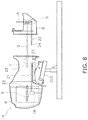
- FIG. 8 is a diagram showing a method of assembling the outboard motor 1 .
- an upper body 1 a of the outboard motor 1 is supported by a fixture 200 while being horizontally mounted.
- the upper body 1 a of the outboard motor 1 includes the engine cowl 6 , the upper housing 7 , the crankshaft 9 , and the first shaft 21 .
- the lower housing 8 includes the driveshaft 3 and the second shaft 22 .
- the driveshaft 3 is firstly inserted into the upper housing 7 .
- the fourth spline 26 of the driveshaft 3 is meshed with the third spline 25 of the crankshaft 9 . Accordingly, the driveshaft 3 is coupled to the crankshaft 9 .
- the fourth spline 26 of the driveshaft 3 is not appropriately meshed with the third spline 25 of the crankshaft 9 , the fourth spline 26 is able to be meshed with the third spline 25 by minutely adjusting the position of either the driveshaft 3 or the lower housing 8 .
- the second spline 24 of the second shaft 22 is meshed with the first spline 23 of the first shaft 21 . Accordingly, the second shaft 22 is coupled to the first shaft 21 .
- the circumferential width W 1 of each groove 33 provided on the distal end 31 is larger than the circumferential width W 2 of each groove 34 provided on the body 32 .
- the root diameter ⁇ 1 of each groove 33 provided on the distal end 31 is smaller than the root diameter ⁇ 2 of each groove 34 provided on the body 32 . Because of this, even when the first spline 23 and the second spline 24 are misaligned in position, the second spline 24 is able to be easily meshed at the distal end 31 with the first spline 23 . Accordingly, attaching the lower housing 8 to the upper housing 7 is easy. On the other hand, when the second spline 24 is meshed at the body 32 with the first spline 23 , wobbling when coupling the first spline 23 and the second spline 24 is reduced to a small amount.
- the second spline 24 is preferably provided on the second shaft 22 of the shift member 17 .
- the second spline 24 may be provided on the driveshaft 3 .
- structures similar to the second spline 24 may be provided on both the driveshaft 3 and the second shaft 22 of the shift member 17 , respectively.
- the first and second processes are preferably performed by the common hobbing cutter 100 .
- the first and second processes may be performed by different hobbing cutters.
- at least one of the first and second processes may be performed by a cutting machine other than the hobbing cutter 100 .
- the second process is preferably performed after the first process is performed.
- the first process may be performed after the second process is performed.
- the second process and the first process may be simultaneously performed.
- the lower housing 8 may be assembled to the upper body 1 a , while the upper body 1 a is tilted with respect to the horizontal direction.
- the lower housing 8 may be assembled to the upper body 1 a , while the upper body 1 a stands in the vertical direction.
Landscapes
- Engineering & Computer Science (AREA)
- Mechanical Engineering (AREA)
- Chemical & Material Sciences (AREA)
- Combustion & Propulsion (AREA)
- Ocean & Marine Engineering (AREA)
- Shafts, Cranks, Connecting Bars, And Related Bearings (AREA)
Abstract
Description
Claims (15)
Applications Claiming Priority (3)
| Application Number | Priority Date | Filing Date | Title |
|---|---|---|---|
| JP2018201505A JP7383376B2 (en) | 2018-10-26 | 2018-10-26 | Outboard motor and outboard motor shaft manufacturing method |
| JP2018-201505 | 2018-10-26 | ||
| JPJP2018-201505 | 2018-10-26 |
Publications (2)
| Publication Number | Publication Date |
|---|---|
| US20200130801A1 US20200130801A1 (en) | 2020-04-30 |
| US11091242B2 true US11091242B2 (en) | 2021-08-17 |
Family
ID=70324961
Family Applications (1)
| Application Number | Title | Priority Date | Filing Date |
|---|---|---|---|
| US16/574,204 Active 2040-01-06 US11091242B2 (en) | 2018-10-26 | 2019-09-18 | Outboard motor and method of manufacturing shaft for outboard motor |
Country Status (2)
| Country | Link |
|---|---|
| US (1) | US11091242B2 (en) |
| JP (1) | JP7383376B2 (en) |
Families Citing this family (1)
| Publication number | Priority date | Publication date | Assignee | Title |
|---|---|---|---|---|
| JP2022112788A (en) * | 2021-01-22 | 2022-08-03 | ヤマハ発動機株式会社 | Outboard engine, ship, and ship propeller |
Citations (3)
| Publication number | Priority date | Publication date | Assignee | Title |
|---|---|---|---|---|
| US2780146A (en) * | 1954-01-18 | 1957-02-05 | Illinois Tool Works | Gear shaving |
| JP2003214162A (en) | 2002-01-25 | 2003-07-30 | Yamaha Marine Co Ltd | Outboard motor |
| US8545125B2 (en) * | 2009-06-01 | 2013-10-01 | Baker Hughes Incorporated | Non-parallel splined hub and shaft connection |
Family Cites Families (7)
| Publication number | Priority date | Publication date | Assignee | Title |
|---|---|---|---|---|
| JPS5977620U (en) * | 1982-11-18 | 1984-05-25 | 光洋精工株式会社 | spline fitting |
| JPS63160437U (en) * | 1987-04-08 | 1988-10-20 | ||
| JPH05337736A (en) * | 1992-06-04 | 1993-12-21 | Fuchimoto Jukogyo Kk | Spline shaft manufacturing method |
| JP2000236705A (en) * | 1999-02-24 | 2000-09-05 | Iseki & Co Ltd | Interlocking axis of tractor working machine |
| JP4223145B2 (en) * | 1999-06-22 | 2009-02-12 | 株式会社ジェイテクト | Cylinder |
| JP2006103554A (en) | 2004-10-06 | 2006-04-20 | Kanzaki Kokyukoki Mfg Co Ltd | Speed-reducing reversing gear for ship |
| JP6103925B2 (en) * | 2012-12-26 | 2017-03-29 | 株式会社クボタ | Pump-mounted transmission and pump |
-
2018
- 2018-10-26 JP JP2018201505A patent/JP7383376B2/en active Active
-
2019
- 2019-09-18 US US16/574,204 patent/US11091242B2/en active Active
Patent Citations (4)
| Publication number | Priority date | Publication date | Assignee | Title |
|---|---|---|---|---|
| US2780146A (en) * | 1954-01-18 | 1957-02-05 | Illinois Tool Works | Gear shaving |
| JP2003214162A (en) | 2002-01-25 | 2003-07-30 | Yamaha Marine Co Ltd | Outboard motor |
| US6814635B1 (en) * | 2002-01-25 | 2004-11-09 | Yamaha Marine Kabushiki Kaisha | Vertically extendable arrangement for marine propulsion device |
| US8545125B2 (en) * | 2009-06-01 | 2013-10-01 | Baker Hughes Incorporated | Non-parallel splined hub and shaft connection |
Also Published As
| Publication number | Publication date |
|---|---|
| JP7383376B2 (en) | 2023-11-20 |
| JP2020066379A (en) | 2020-04-30 |
| US20200130801A1 (en) | 2020-04-30 |
Similar Documents
| Publication | Publication Date | Title |
|---|---|---|
| EP3613663B1 (en) | Hybrid type vessel propulsion apparatus | |
| KR20100099762A (en) | Switchable rotation drive device | |
| US11091242B2 (en) | Outboard motor and method of manufacturing shaft for outboard motor | |
| JP2002147580A (en) | Lubrication structure of differential case and its processing method | |
| JPH0715302B2 (en) | Ship propulsion | |
| JP3182161B2 (en) | Ship propulsion device | |
| US20210239208A1 (en) | Shift mechanism for power transmission device | |
| US8142099B2 (en) | Automatic transmission | |
| JPH0715303B2 (en) | Ship propulsion | |
| EP3760897A1 (en) | Outboard motor | |
| US12397891B2 (en) | Outboard motor and drive shaft assembling method | |
| JP2007205365A (en) | Bevel gear and method for forming the same | |
| EP2492187A1 (en) | Power transmission device of outboard motor | |
| WO2013187111A1 (en) | Dog clutch | |
| EP2492186B1 (en) | Power transmission device of outboard motor | |
| US12012192B1 (en) | Apertured propeller assemblies and methods | |
| JP2002308185A (en) | Outboard motor drive | |
| EP1528298A1 (en) | Shift control mechanism for a synchromesh-type transmission | |
| EP2492188B1 (en) | Power transmission device of outboard motor | |
| US11772762B2 (en) | Propeller for vessel propulsion apparatus and vessel propulsion apparatus | |
| JP4687242B2 (en) | Input shaft of industrial vehicle transmission, industrial vehicle transmission and industrial vehicle, and manufacturing method of industrial vehicle transmission | |
| JP3455592B2 (en) | Thrust bearing with stepped through hole | |
| KR102258493B1 (en) | Turning Gear | |
| JP6177078B2 (en) | Spline fitting structure | |
| KR200301141Y1 (en) | Boring machine feed apparatus |
Legal Events
| Date | Code | Title | Description |
|---|---|---|---|
| AS | Assignment |
Owner name: YAMAHA HATSUDOKI KABUSHIKI KAISHA, JAPAN Free format text: ASSIGNMENT OF ASSIGNORS INTEREST;ASSIGNORS:IKEGAYA, YUKI;YUKISHIMA, KENJI;REEL/FRAME:050414/0175 Effective date: 20190826 |
|
| FEPP | Fee payment procedure |
Free format text: ENTITY STATUS SET TO UNDISCOUNTED (ORIGINAL EVENT CODE: BIG.); ENTITY STATUS OF PATENT OWNER: LARGE ENTITY |
|
| STPP | Information on status: patent application and granting procedure in general |
Free format text: NON FINAL ACTION MAILED |
|
| STPP | Information on status: patent application and granting procedure in general |
Free format text: RESPONSE TO NON-FINAL OFFICE ACTION ENTERED AND FORWARDED TO EXAMINER |
|
| STPP | Information on status: patent application and granting procedure in general |
Free format text: NOTICE OF ALLOWANCE MAILED -- APPLICATION RECEIVED IN OFFICE OF PUBLICATIONS |
|
| STPP | Information on status: patent application and granting procedure in general |
Free format text: PUBLICATIONS -- ISSUE FEE PAYMENT RECEIVED |
|
| STPP | Information on status: patent application and granting procedure in general |
Free format text: PUBLICATIONS -- ISSUE FEE PAYMENT VERIFIED |
|
| STCF | Information on status: patent grant |
Free format text: PATENTED CASE |
|
| MAFP | Maintenance fee payment |
Free format text: PAYMENT OF MAINTENANCE FEE, 4TH YEAR, LARGE ENTITY (ORIGINAL EVENT CODE: M1551); ENTITY STATUS OF PATENT OWNER: LARGE ENTITY Year of fee payment: 4 |