US11079629B2 - LED backlight module - Google Patents
LED backlight module Download PDFInfo
- Publication number
- US11079629B2 US11079629B2 US16/683,281 US201916683281A US11079629B2 US 11079629 B2 US11079629 B2 US 11079629B2 US 201916683281 A US201916683281 A US 201916683281A US 11079629 B2 US11079629 B2 US 11079629B2
- Authority
- US
- United States
- Prior art keywords
- light emitting
- blue
- emitting diode
- enhancement film
- quantum dot
- Prior art date
- Legal status (The legal status is an assumption and is not a legal conclusion. Google has not performed a legal analysis and makes no representation as to the accuracy of the status listed.)
- Active
Links
- 239000002096 quantum dot Substances 0.000 claims abstract description 110
- GWEVSGVZZGPLCZ-UHFFFAOYSA-N Titan oxide Chemical compound O=[Ti]=O GWEVSGVZZGPLCZ-UHFFFAOYSA-N 0.000 claims description 20
- 229920000728 polyester Polymers 0.000 claims description 12
- -1 polyethylene terephthalate Polymers 0.000 claims description 8
- 229920000139 polyethylene terephthalate Polymers 0.000 claims description 8
- 239000005020 polyethylene terephthalate Substances 0.000 claims description 8
- 230000009977 dual effect Effects 0.000 claims description 2
- 239000010408 film Substances 0.000 description 90
- 239000000463 material Substances 0.000 description 11
- 238000010586 diagram Methods 0.000 description 8
- 238000001228 spectrum Methods 0.000 description 8
- 239000004973 liquid crystal related substance Substances 0.000 description 6
- 239000012788 optical film Substances 0.000 description 4
- 230000000694 effects Effects 0.000 description 3
- 239000003086 colorant Substances 0.000 description 2
- 239000000975 dye Substances 0.000 description 2
- 238000012986 modification Methods 0.000 description 2
- 230000004048 modification Effects 0.000 description 2
- 230000003287 optical effect Effects 0.000 description 2
- 239000011248 coating agent Substances 0.000 description 1
- 238000000576 coating method Methods 0.000 description 1
- 239000012141 concentrate Substances 0.000 description 1
- 238000009826 distribution Methods 0.000 description 1
- 238000003384 imaging method Methods 0.000 description 1
Images


Classifications
-
- G—PHYSICS
- G02—OPTICS
- G02B—OPTICAL ELEMENTS, SYSTEMS OR APPARATUS
- G02B6/00—Light guides; Structural details of arrangements comprising light guides and other optical elements, e.g. couplings
- G02B6/0001—Light guides; Structural details of arrangements comprising light guides and other optical elements, e.g. couplings specially adapted for lighting devices or systems
- G02B6/0011—Light guides; Structural details of arrangements comprising light guides and other optical elements, e.g. couplings specially adapted for lighting devices or systems the light guides being planar or of plate-like form
- G02B6/0033—Means for improving the coupling-out of light from the light guide
- G02B6/005—Means for improving the coupling-out of light from the light guide provided by one optical element, or plurality thereof, placed on the light output side of the light guide
- G02B6/0051—Diffusing sheet or layer
-
- G—PHYSICS
- G02—OPTICS
- G02B—OPTICAL ELEMENTS, SYSTEMS OR APPARATUS
- G02B6/00—Light guides; Structural details of arrangements comprising light guides and other optical elements, e.g. couplings
- G02B6/0001—Light guides; Structural details of arrangements comprising light guides and other optical elements, e.g. couplings specially adapted for lighting devices or systems
- G02B6/0011—Light guides; Structural details of arrangements comprising light guides and other optical elements, e.g. couplings specially adapted for lighting devices or systems the light guides being planar or of plate-like form
- G02B6/0033—Means for improving the coupling-out of light from the light guide
- G02B6/005—Means for improving the coupling-out of light from the light guide provided by one optical element, or plurality thereof, placed on the light output side of the light guide
- G02B6/0053—Prismatic sheet or layer; Brightness enhancement element, sheet or layer
-
- G—PHYSICS
- G02—OPTICS
- G02B—OPTICAL ELEMENTS, SYSTEMS OR APPARATUS
- G02B6/00—Light guides; Structural details of arrangements comprising light guides and other optical elements, e.g. couplings
- G02B6/0001—Light guides; Structural details of arrangements comprising light guides and other optical elements, e.g. couplings specially adapted for lighting devices or systems
- G02B6/0011—Light guides; Structural details of arrangements comprising light guides and other optical elements, e.g. couplings specially adapted for lighting devices or systems the light guides being planar or of plate-like form
- G02B6/0033—Means for improving the coupling-out of light from the light guide
- G02B6/005—Means for improving the coupling-out of light from the light guide provided by one optical element, or plurality thereof, placed on the light output side of the light guide
- G02B6/0055—Reflecting element, sheet or layer
-
- G—PHYSICS
- G02—OPTICS
- G02B—OPTICAL ELEMENTS, SYSTEMS OR APPARATUS
- G02B6/00—Light guides; Structural details of arrangements comprising light guides and other optical elements, e.g. couplings
- G02B6/0001—Light guides; Structural details of arrangements comprising light guides and other optical elements, e.g. couplings specially adapted for lighting devices or systems
- G02B6/0011—Light guides; Structural details of arrangements comprising light guides and other optical elements, e.g. couplings specially adapted for lighting devices or systems the light guides being planar or of plate-like form
- G02B6/0081—Mechanical or electrical aspects of the light guide and light source in the lighting device peculiar to the adaptation to planar light guides, e.g. concerning packaging
- G02B6/0086—Positioning aspects
- G02B6/0088—Positioning aspects of the light guide or other optical sheets in the package
-
- G—PHYSICS
- G02—OPTICS
- G02F—OPTICAL DEVICES OR ARRANGEMENTS FOR THE CONTROL OF LIGHT BY MODIFICATION OF THE OPTICAL PROPERTIES OF THE MEDIA OF THE ELEMENTS INVOLVED THEREIN; NON-LINEAR OPTICS; FREQUENCY-CHANGING OF LIGHT; OPTICAL LOGIC ELEMENTS; OPTICAL ANALOGUE/DIGITAL CONVERTERS
- G02F1/00—Devices or arrangements for the control of the intensity, colour, phase, polarisation or direction of light arriving from an independent light source, e.g. switching, gating or modulating; Non-linear optics
- G02F1/01—Devices or arrangements for the control of the intensity, colour, phase, polarisation or direction of light arriving from an independent light source, e.g. switching, gating or modulating; Non-linear optics for the control of the intensity, phase, polarisation or colour
- G02F1/13—Devices or arrangements for the control of the intensity, colour, phase, polarisation or direction of light arriving from an independent light source, e.g. switching, gating or modulating; Non-linear optics for the control of the intensity, phase, polarisation or colour based on liquid crystals, e.g. single liquid crystal display cells
- G02F1/133—Constructional arrangements; Operation of liquid crystal cells; Circuit arrangements
- G02F1/1333—Constructional arrangements; Manufacturing methods
- G02F1/1335—Structural association of cells with optical devices, e.g. polarisers or reflectors
- G02F1/1336—Illuminating devices
- G02F1/133602—Direct backlight
- G02F1/133603—Direct backlight with LEDs
-
- G—PHYSICS
- G02—OPTICS
- G02F—OPTICAL DEVICES OR ARRANGEMENTS FOR THE CONTROL OF LIGHT BY MODIFICATION OF THE OPTICAL PROPERTIES OF THE MEDIA OF THE ELEMENTS INVOLVED THEREIN; NON-LINEAR OPTICS; FREQUENCY-CHANGING OF LIGHT; OPTICAL LOGIC ELEMENTS; OPTICAL ANALOGUE/DIGITAL CONVERTERS
- G02F1/00—Devices or arrangements for the control of the intensity, colour, phase, polarisation or direction of light arriving from an independent light source, e.g. switching, gating or modulating; Non-linear optics
- G02F1/01—Devices or arrangements for the control of the intensity, colour, phase, polarisation or direction of light arriving from an independent light source, e.g. switching, gating or modulating; Non-linear optics for the control of the intensity, phase, polarisation or colour
- G02F1/13—Devices or arrangements for the control of the intensity, colour, phase, polarisation or direction of light arriving from an independent light source, e.g. switching, gating or modulating; Non-linear optics for the control of the intensity, phase, polarisation or colour based on liquid crystals, e.g. single liquid crystal display cells
- G02F1/133—Constructional arrangements; Operation of liquid crystal cells; Circuit arrangements
- G02F1/1333—Constructional arrangements; Manufacturing methods
- G02F1/1335—Structural association of cells with optical devices, e.g. polarisers or reflectors
- G02F1/1336—Illuminating devices
- G02F1/133602—Direct backlight
- G02F1/133605—Direct backlight including specially adapted reflectors
-
- G—PHYSICS
- G02—OPTICS
- G02F—OPTICAL DEVICES OR ARRANGEMENTS FOR THE CONTROL OF LIGHT BY MODIFICATION OF THE OPTICAL PROPERTIES OF THE MEDIA OF THE ELEMENTS INVOLVED THEREIN; NON-LINEAR OPTICS; FREQUENCY-CHANGING OF LIGHT; OPTICAL LOGIC ELEMENTS; OPTICAL ANALOGUE/DIGITAL CONVERTERS
- G02F1/00—Devices or arrangements for the control of the intensity, colour, phase, polarisation or direction of light arriving from an independent light source, e.g. switching, gating or modulating; Non-linear optics
- G02F1/01—Devices or arrangements for the control of the intensity, colour, phase, polarisation or direction of light arriving from an independent light source, e.g. switching, gating or modulating; Non-linear optics for the control of the intensity, phase, polarisation or colour
- G02F1/13—Devices or arrangements for the control of the intensity, colour, phase, polarisation or direction of light arriving from an independent light source, e.g. switching, gating or modulating; Non-linear optics for the control of the intensity, phase, polarisation or colour based on liquid crystals, e.g. single liquid crystal display cells
- G02F1/133—Constructional arrangements; Operation of liquid crystal cells; Circuit arrangements
- G02F1/1333—Constructional arrangements; Manufacturing methods
- G02F1/1335—Structural association of cells with optical devices, e.g. polarisers or reflectors
- G02F1/1336—Illuminating devices
- G02F1/133602—Direct backlight
- G02F1/133606—Direct backlight including a specially adapted diffusing, scattering or light controlling members
-
- G—PHYSICS
- G02—OPTICS
- G02F—OPTICAL DEVICES OR ARRANGEMENTS FOR THE CONTROL OF LIGHT BY MODIFICATION OF THE OPTICAL PROPERTIES OF THE MEDIA OF THE ELEMENTS INVOLVED THEREIN; NON-LINEAR OPTICS; FREQUENCY-CHANGING OF LIGHT; OPTICAL LOGIC ELEMENTS; OPTICAL ANALOGUE/DIGITAL CONVERTERS
- G02F1/00—Devices or arrangements for the control of the intensity, colour, phase, polarisation or direction of light arriving from an independent light source, e.g. switching, gating or modulating; Non-linear optics
- G02F1/01—Devices or arrangements for the control of the intensity, colour, phase, polarisation or direction of light arriving from an independent light source, e.g. switching, gating or modulating; Non-linear optics for the control of the intensity, phase, polarisation or colour
- G02F1/13—Devices or arrangements for the control of the intensity, colour, phase, polarisation or direction of light arriving from an independent light source, e.g. switching, gating or modulating; Non-linear optics for the control of the intensity, phase, polarisation or colour based on liquid crystals, e.g. single liquid crystal display cells
- G02F1/133—Constructional arrangements; Operation of liquid crystal cells; Circuit arrangements
- G02F1/1333—Constructional arrangements; Manufacturing methods
- G02F1/1335—Structural association of cells with optical devices, e.g. polarisers or reflectors
- G02F1/1336—Illuminating devices
- G02F1/133602—Direct backlight
- G02F1/133609—Direct backlight including means for improving the color mixing, e.g. white
-
- G—PHYSICS
- G02—OPTICS
- G02F—OPTICAL DEVICES OR ARRANGEMENTS FOR THE CONTROL OF LIGHT BY MODIFICATION OF THE OPTICAL PROPERTIES OF THE MEDIA OF THE ELEMENTS INVOLVED THEREIN; NON-LINEAR OPTICS; FREQUENCY-CHANGING OF LIGHT; OPTICAL LOGIC ELEMENTS; OPTICAL ANALOGUE/DIGITAL CONVERTERS
- G02F1/00—Devices or arrangements for the control of the intensity, colour, phase, polarisation or direction of light arriving from an independent light source, e.g. switching, gating or modulating; Non-linear optics
- G02F1/01—Devices or arrangements for the control of the intensity, colour, phase, polarisation or direction of light arriving from an independent light source, e.g. switching, gating or modulating; Non-linear optics for the control of the intensity, phase, polarisation or colour
- G02F1/13—Devices or arrangements for the control of the intensity, colour, phase, polarisation or direction of light arriving from an independent light source, e.g. switching, gating or modulating; Non-linear optics for the control of the intensity, phase, polarisation or colour based on liquid crystals, e.g. single liquid crystal display cells
- G02F1/133—Constructional arrangements; Operation of liquid crystal cells; Circuit arrangements
- G02F1/1333—Constructional arrangements; Manufacturing methods
- G02F1/1335—Structural association of cells with optical devices, e.g. polarisers or reflectors
- G02F1/1336—Illuminating devices
- G02F1/133602—Direct backlight
- G02F1/133611—Direct backlight including means for improving the brightness uniformity
-
- G—PHYSICS
- G02—OPTICS
- G02F—OPTICAL DEVICES OR ARRANGEMENTS FOR THE CONTROL OF LIGHT BY MODIFICATION OF THE OPTICAL PROPERTIES OF THE MEDIA OF THE ELEMENTS INVOLVED THEREIN; NON-LINEAR OPTICS; FREQUENCY-CHANGING OF LIGHT; OPTICAL LOGIC ELEMENTS; OPTICAL ANALOGUE/DIGITAL CONVERTERS
- G02F1/00—Devices or arrangements for the control of the intensity, colour, phase, polarisation or direction of light arriving from an independent light source, e.g. switching, gating or modulating; Non-linear optics
- G02F1/01—Devices or arrangements for the control of the intensity, colour, phase, polarisation or direction of light arriving from an independent light source, e.g. switching, gating or modulating; Non-linear optics for the control of the intensity, phase, polarisation or colour
- G02F1/13—Devices or arrangements for the control of the intensity, colour, phase, polarisation or direction of light arriving from an independent light source, e.g. switching, gating or modulating; Non-linear optics for the control of the intensity, phase, polarisation or colour based on liquid crystals, e.g. single liquid crystal display cells
- G02F1/133—Constructional arrangements; Operation of liquid crystal cells; Circuit arrangements
- G02F1/1333—Constructional arrangements; Manufacturing methods
- G02F1/1335—Structural association of cells with optical devices, e.g. polarisers or reflectors
- G02F1/1336—Illuminating devices
- G02F1/133615—Edge-illuminating devices, i.e. illuminating from the side
-
- G—PHYSICS
- G02—OPTICS
- G02F—OPTICAL DEVICES OR ARRANGEMENTS FOR THE CONTROL OF LIGHT BY MODIFICATION OF THE OPTICAL PROPERTIES OF THE MEDIA OF THE ELEMENTS INVOLVED THEREIN; NON-LINEAR OPTICS; FREQUENCY-CHANGING OF LIGHT; OPTICAL LOGIC ELEMENTS; OPTICAL ANALOGUE/DIGITAL CONVERTERS
- G02F1/00—Devices or arrangements for the control of the intensity, colour, phase, polarisation or direction of light arriving from an independent light source, e.g. switching, gating or modulating; Non-linear optics
- G02F1/01—Devices or arrangements for the control of the intensity, colour, phase, polarisation or direction of light arriving from an independent light source, e.g. switching, gating or modulating; Non-linear optics for the control of the intensity, phase, polarisation or colour
- G02F1/13—Devices or arrangements for the control of the intensity, colour, phase, polarisation or direction of light arriving from an independent light source, e.g. switching, gating or modulating; Non-linear optics for the control of the intensity, phase, polarisation or colour based on liquid crystals, e.g. single liquid crystal display cells
- G02F1/133—Constructional arrangements; Operation of liquid crystal cells; Circuit arrangements
- G02F1/1333—Constructional arrangements; Manufacturing methods
- G02F1/1335—Structural association of cells with optical devices, e.g. polarisers or reflectors
- G02F1/1336—Illuminating devices
- G02F1/133602—Direct backlight
- G02F1/133606—Direct backlight including a specially adapted diffusing, scattering or light controlling members
- G02F1/133607—Direct backlight including a specially adapted diffusing, scattering or light controlling members the light controlling member including light directing or refracting elements, e.g. prisms or lenses
-
- G—PHYSICS
- G02—OPTICS
- G02F—OPTICAL DEVICES OR ARRANGEMENTS FOR THE CONTROL OF LIGHT BY MODIFICATION OF THE OPTICAL PROPERTIES OF THE MEDIA OF THE ELEMENTS INVOLVED THEREIN; NON-LINEAR OPTICS; FREQUENCY-CHANGING OF LIGHT; OPTICAL LOGIC ELEMENTS; OPTICAL ANALOGUE/DIGITAL CONVERTERS
- G02F1/00—Devices or arrangements for the control of the intensity, colour, phase, polarisation or direction of light arriving from an independent light source, e.g. switching, gating or modulating; Non-linear optics
- G02F1/01—Devices or arrangements for the control of the intensity, colour, phase, polarisation or direction of light arriving from an independent light source, e.g. switching, gating or modulating; Non-linear optics for the control of the intensity, phase, polarisation or colour
- G02F1/13—Devices or arrangements for the control of the intensity, colour, phase, polarisation or direction of light arriving from an independent light source, e.g. switching, gating or modulating; Non-linear optics for the control of the intensity, phase, polarisation or colour based on liquid crystals, e.g. single liquid crystal display cells
- G02F1/133—Constructional arrangements; Operation of liquid crystal cells; Circuit arrangements
- G02F1/1333—Constructional arrangements; Manufacturing methods
- G02F1/1335—Structural association of cells with optical devices, e.g. polarisers or reflectors
- G02F1/1336—Illuminating devices
- G02F1/133614—Illuminating devices using photoluminescence, e.g. phosphors illuminated by UV or blue light
-
- G—PHYSICS
- G02—OPTICS
- G02F—OPTICAL DEVICES OR ARRANGEMENTS FOR THE CONTROL OF LIGHT BY MODIFICATION OF THE OPTICAL PROPERTIES OF THE MEDIA OF THE ELEMENTS INVOLVED THEREIN; NON-LINEAR OPTICS; FREQUENCY-CHANGING OF LIGHT; OPTICAL LOGIC ELEMENTS; OPTICAL ANALOGUE/DIGITAL CONVERTERS
- G02F2202/00—Materials and properties
- G02F2202/36—Micro- or nanomaterials
Definitions
- the present disclosure generally relates to a backlight module. More particularly, the present disclosure relates to a light emitting diode backlight module.
- the display devices currently can integrate camera, communication, and display capabilities therein.
- the resolutions of the displays are also increasing over time, for example, the Full HD display devices are replaced by 4K display devices, and the 4 k display devices may be further replaced by the 8K display devices.
- the liquid crystal displays bring not only higher resolutions but also more realistic pictures to the users.
- the backlight modules of the display devices cannot support wide color gamut or provide wide range of brightness for high dynamic range imaging (HDR) on the LCD panel, the LCD panel with the improved resolutions can only imperfectly present a flawed scene with unreal colors to the users, rather than authentically present an immersive scene with real colors.
- HDR high dynamic range imaging
- the best performance of the wide color gamut and high-brightness HDR effects presented by the conventional liquid crystal displays are about 100% NTSC color gamut with capability of 1000 nits HDR brightness, which is close to the color television broadcasting standards set by the National Television System Committee (NTSC).
- NTSC National Television System Committee
- the color and brightness performance of displays limited to such display effect requirements is still insufficient to provide accurate presentations of high resolution images.
- improving the color gamut and brightness performance of the liquid crystal displays will contribute to accurately display the high resolution images and effectively improve the image qualities of the liquid crystal displays.
- One objective of the embodiments of the present invention is to provide a light emitting diode backlight module to improve the color gamut and brightness performance of the liquid crystal display so as to improve the image quality thereof.
- the embodiments of the present invention provides a light emitting diode backlight module including a light emitting diode light source, a quantum dot enhancement film, a diffuser plate, and a blue light reflector.
- the light emitting diode light source has a plurality of blue light emitting diodes.
- the quantum dot enhancement film is excited by the blue lights emitted by the blue light emitting diodes so as to emit red lights and green lights.
- the diffuser plate is disposed between the light emitting diode light source and the quantum dot enhancement film.
- the blue light reflector is disposed at a side, opposite to the quantum dot enhancement film, of the diffuser plate to reflect a part of the blue lights reflected by the diffuser plate to the quantum dot enhancement film.
- a light emitting diode backlight module in another aspect, includes a light emitting diode light source, a quantum dot enhancement film, a diffuser plate, and a blue light filter and reflector.
- the light emitting diode light source has a plurality of blue light emitting diodes.
- the quantum dot enhancement film is excited by the blue lights emitted by the blue light emitting diodes so as to emit red lights and green lights.
- the diffuser plate is disposed between the light emitting diode light source and the quantum dot enhancement film.
- the blue light filter and reflector is disposed between the diffuser plate and the quantum dot enhancement film to guide the blue lights emitted by the blue light emitting diodes to the quantum dot enhancement film and reflect a part of blue lights reflected by the quantum dot enhancement film to the quantum dot enhancement film again.
- a light emitting diode backlight module includes a light emitting diode light source, a quantum dot enhancement film, a diffuser plate, a blue light reflector, and a blue light filter and reflector.
- the light emitting diode light source has a plurality of blue light emitting diodes.
- the quantum dot enhancement film is excited by the blue lights emitted by the blue light emitting diodes so as to emit red lights and green lights.
- the diffuser plate is disposed between the light emitting diode light source and the quantum dot enhancement film.
- the blue light reflector is disposed at a side, opposite to the quantum dot enhancement film, of the diffuser plate to reflect a part of blue lights reflected by the diffuser plate to the quantum dot enhancement film.
- the blue light filter and reflector is disposed between the diffuser plate and the quantum dot enhancement film to guide the blue lights emitted by the blue light emitting diodes to the quantum dot enhancement film and reflect a part of blue lights reflected by the quantum dot enhancement film to the quantum dot enhancement film again.
- the blue light emitting diodes include a plurality of mini light emitting diodes, e.g. a plurality of molded chip scale package (mCSP) light emitting diodes.
- mCSP molded chip scale package
- the light emitting diode backlight module further includes a brightness enhancement film and a diffuser sheet sequentially disposed on a surface of the quantum dot enhancement film.
- the brightness enhancement film includes a first prism sheet and a second prism sheet.
- the light emitting diode backlight module is a direct type light emitting diode backlight module.
- the light emitting diode backlight module is an edge-lit light emitting diode backlight module, and the light emitting diode backlight module further includes a light guide plate disposed on a surface, opposite to the quantum dot enhancement film, of the diffuser plate.
- the light emitting diode backlight module further includes a light guide plate disposed between the diffuser plate and the blue light reflector.
- the blue light reflector includes a polyester base and a TiO2 film.
- the polyester base is a 0.188 mm polyethylene terephthalate (PET) film and a thickness of the TiO2 film is about 100 nm.
- PET polyethylene terephthalate
- the blue light filter and reflector is a polyester base and an Azo compound dye film.
- a surface, close to the quantum dot enhancement film, of the blue light filter and reflector is blue, and a surface, close to the diffuser plate, of the blue light filter and reflector is yellow.
- the blue light wavelength of the blue light emitting diodes is about 430 nm ⁇ 480 nm.
- the light emitting diode backlight module can effectively improve the utilization of the blue lights and excite the quantum dot enhancement film with blue lights having wavelengths within a predetermined range to emit desired white lights, which improves the spectrum characteristics of the red lights and green lights emitted by the quantum dot enhancement film and further enhances the luminous efficiency, brightness and color gamut performance of the light emitting diode backlight module.
- FIG. 1 illustrates a schematic diagram showing a light emitting diode backlight module according to one embodiment of the present invention.
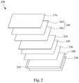
- FIG. 2 illustrates a schematic diagram showing a light emitting diode backlight module according to another embodiment of the present invention.
- FIG. 3 illustrates a schematic diagram showing a part of light paths of the light emitting diode backlight module according to one embodiment of the present invention.
- FIG. 4 illustrates a schematic diagram showing another part of light paths of the light emitting diode backlight module according to one embodiment of the present invention.
- FIG. 5 illustrates an enlarged diagram of the light paths of FIG. 4 .
- FIG. 6 illustrates a spectrum comparison diagram of a conventional light emitting diode backlight module and the light emitting diode backlight module according to one embodiment of the present invention.
- FIG. 1 illustrates a direct type light emitting diode backlight module.
- FIG. 2 illustrates an edge-lit light emitting diode backlight module.
- FIG. 3 illustrates a part of light paths of the light emitting diode backlight module,
- FIG. 4 illustrates another part of light paths of the light emitting diode backlight module, and
- FIG. 5 illustrates an enlarged diagram of the light paths of FIG. 4 .
- FIG. 6 illustrates a spectrum comparison diagram of a conventional light emitting diode backlight module and the light emitting diode backlight module according to one embodiment of the present invention.
- a light emitting diode backlight module 100 which is a direct type backlight module, includes a light emitting diode light source 110 , a quantum dot enhancement film 150 , a blue light filter and reflector 140 , a diffuser plate 130 and a blue light reflector 120 .
- the light emitting diode light source 110 includes a plurality of blue light emitting diodes 112 disposed on a circuit board 114 .
- the quantum dot enhancement film 150 is configured to receive the blue lights emitted by the blue light emitting diodes 112 , which excite the quantum dot material within the quantum dot enhancement film 150 to emit the red lights and the green lights.
- the diffuser plate 130 is disposed between the light emitting diode light source 110 and the quantum dot enhancement film 150 .
- the blue light reflector 120 can be a partially transparent blue light reflective film, which is capable of partially transmitting the blue lights, or an opaque blue light reflecting sheet, which completely reflects the blue lights.
- the blue light reflector 120 is disposed on one side of the diffuser plate 130 , which is opposite to the quantum dot enhancement film 150 , so a part of the blue lights reflected by the diffuser plate 130 can be reflected back to the quantum dot enhancement film 150 .
- the blue light reflector 120 further includes a plurality of opening 122 .
- the blue light emitting diodes 112 are exposed by the openings 122 when the blue light reflector 120 covers on the circuit board 114 , so the blue lights 310 radiate toward the diffuser plate 130 when the blue lights are emitted by the blue light emitting diodes 112 .
- Part of the first-order blue lights 310 transmitted from the blue light emitting diodes 112 may be reflected by the diffuser plate 130 , i.e. the first-order reflected lights 320 .
- the first-order reflected lights 320 return to the blue light reflector 120 covering the circuit board 114 , which reflect the lights 320 again.
- the blue light reflector 120 may be designed as to reflect the blue lights having predetermined wavelengths. In some embodiments, the blue light reflector 120 reflects the blue lights having wavelengths within 420 nm to 480 nm.
- the blue light emitting diodes 112 includes a plurality of mini light emitting diodes (Mini LEDs), and the Mini LEDs can be molded chip scale package (mCSP) Mini LEDs.
- Mini LEDs mini light emitting diodes
- mCSP molded chip scale package
- Part of the first-order blue lights 310 transmitted from the blue light emitting diodes 112 may pass through the diffuser plate 130 as well as the second-order blue lights 330 , which is the lights reflected by the blue light reflector 120 covered on the circuit board 114 , and eventually excite the quantum dot material within the quantum dot enhancement film 150 to emit the white light.
- the blue lights having the predetermined wavelengths may pass through the blue light filter and reflector 140 and form the blue lights 340 for exciting the quantum dot material within the quantum dot enhancement film 150 so as to emit the green lights with 530 nm ⁇ 540 nm wavelengths and the red lights with 630 nm ⁇ 640 nm wavelengths.
- the light emitting diode backlight module 100 may further includes a blue light filter and reflector 140 disposed on a surface of the diffuser plate 130 and located between the diffuser plate 130 and the quantum dot enhancement film 150 , such that the blue lights 410 , which are emitted by the blue light emitting diodes 112 and pass through the diffuser plate 130 , are guided to the quantum dot enhancement film 150 with the blue light filter and reflector 140 .
- the blue light filter and reflector 140 can reflect the lights 430 , which are reflected by the quantum dot enhancement film 150 , back to the quantum dot enhancement film 150 and excite more red lights and green lights to be emitted.
- the desired white lights 440 will be provided.
- a part of the white lights emitted by the quantum dot enhancement film 150 may be reflected back to the blue light filter and reflector 140 .
- the white lights can be separated into the reflected blue lights 510 , the reflected green lights 520 and the reflected red lights 530 .
- the reflected green lights 520 and the reflected red lights 530 can be absorbed by the dyes or coating of the blue light filter and reflector 140 and the reflected blue lights 510 can be reflected back as the blue lights 540 .
- more blue lights are provided to excite the quantum dot material within the quantum dot enhancement film 150 , and more white lights are emitted.
- the brightness and efficiency of the light emitting diode backlight module 100 are therefore improved.
- the light emitting diode backlight module 100 could provide more blue lights to excite more red lights and green lights and the brightness of the light emitting diode backlight module 100 is further improved about 7% ⁇ 10%.
- the brightness of the light emitting diode backlight module 100 can be improved with the blue light reflector 120 and/or the blue light filter and reflector 140 , alone or in combination, which do not depart from the spirit and scope of the present invention.
- a blue light reflector 120 configured to reflect the blue lights with the predetermined wavelengths, such as 420 nm ⁇ 480 nm, is formed on the surface of the circuit board 114 having the light emitting diode light source 110 disposed.
- the blue light reflector 120 is configured to reflect the blue lights with the predetermined wavelengths to the diffuser plate 130 .
- the lights emitted by the blue light emitting diodes 112 transmit toward to the diffuser plate 130 and the second-order lights reflected by the blue light reflector 120 also radiate to the diffuser plate 130 , and a part of the lights will then pass through the diffuser plate 130 and the blue light filter and reflector 140 and excite the quantum dot enhancement film 150 to emit the white lights.
- the remaining part of the lights transmitted toward to the diffuser plate 130 may not pass through the diffuser plate 130 , and be reflected back to the optical chamber within the backlight module 100 . Such reflected lights will be reflected again with the blue light reflector 120 and the utilization efficiency of the blue lights is therefore improved.
- the package size of the mCSP mini-LED utilized as the blue light emitting diode is smaller than 600 ⁇ m (micrometer).
- the mCSP mini-LED has a material layer or structure, such as TiO2, covering the top portion of the light-emitting diode to change the light intensity distributions of the emitted lights. Since the highly reflective material layer or structure is directly formed above the light-emitting diode so as to redistribute the light patterns of emitted lights from the light-emitting diode, the redistributed light patterns of the light-emitting diode may be similar to the light patterns of emitted lights from the light emitting diode through a secondary optical lens.
- the light emitted by the mCSP mini-LED is blue light, wherein the wavelength of the blue light is between 430 nm and 480 nm.
- the blue light with wavelength between 435 nm and 460 nm can be utilized to improve the efficiency and brightness of the lights emitted by the light emitting diode backlight module 100 , such that the color gamut will be effectively improved and meet the HDR brightness requirements as NTSC 110% and 2000 nits.
- the blue light reflector 120 on the circuit board 114 can reflect the blue lights in reverse direction, including the blue lights reflected by the reflective material on the top of the light emitting diodes and the blue lights reflected by the diffuser plate 130 , back to the diffuser plate 130 and improve the utilization of the blue lights.
- the blue light reflector 120 can be designed as to only reflect the blue lights with 420 nm to 480 nm wavelength.
- the light emitting diode backlight module 100 can provide more blue lights to excite more red lights and green lights, and the brightness can be improved about 7% to 10%.
- the blue light filter and reflector 140 works as a filter of blue lights with a predetermined wavelength, e.g. the blue lights with 420 nm to 480 nm wavelength.
- the blue light filter and reflector 140 ensures that only the blue lights within the predetermined wavelength range can pass through and excite the quantum dot enhancement film 150 , which enhances the color gamut performance thereof by utilizing only the blue lights within the predetermined wavelength range.
- Part of the blue lights passing through the blue light filter and reflector 140 may excite the quantum dot enhancement film 150 to emit the white lights and other part of the blue lights may be reflected by the quantum dot enhancement film 150 , and the blue light filter and reflector 140 may reflect the reflected blue lights back to excite the quantum dot enhancement film 150 , so more white lights can be emitted and the utilization of second-order blue lights can be further improved.
- the surface of the blue light filter and reflector 140 closed to the quantum dot enhancement film 150 is blue, and the surface of the blue light filter and reflector 140 closed to the diffuser plate 130 is yellow. That is to say, the surface where the lights exit the blue light filter and reflector 140 is blue and the surface where the lights enter the blue light filter and reflector 140 is yellow.
- curve 610 is the spectrum curve of a conventional light emitting diode backlight module and curve 620 is the spectrum curve of the light emitting diode backlight module according to one embodiment of the present invention.
- the spectrum curve 620 can provide higher peak value of red lights and green lights which are mixed with the blue lights to produce white lights.
- more white lights can be emitted by the quantum dot enhancement film 150 according to one embodiment of the present invention, which is excited by the blue lights from the light emitting diode backlight module. Therefore, the properties of the full width at half maximum (FWHM) are improved, i.e., a narrower full width at half maximum, higher luminous efficiency and better color gamut can be achieved.
- FWHM full width at half maximum
- the foregoing improved blue light utilization can effectively improve the efficiency of the quantum dot enhancement film 150 about 7% so as to increase the brightness of the light emitting diode backlight module 100 .
- restricting the reflected blue lights within the predetermined wavelength range can improve the performance of color gamut.
- the predetermined wavelength range of the blue lights can excite the quantum dots to provide spectrums with narrower FWHM performance, and the narrower FWHM contributes to the improvement of the color gamut. Therefore, the backlight module of the present invention can concentrate the emitted blue lights within the predetermined wavelength range, which simultaneously improves the FWHM of the emitted lights and the luminous efficiency of the backlight module.
- the blue light reflector 120 attached on the circuit board 114 can include a polyester base and a TiO2 film evaporated on the polyester base.
- the thickness of the TiO2 film may be adjusted to a predetermined dimension in order to conduct different reflection effects for predetermined wavelength ranges.
- the polyester base can be a 0.188 mm polyethylene terephthalate (PET) film and the thickness of the TiO2 film on the base can be about 100 nm.
- the thicknesses of the films can be adjusted to achieve the reflective index as about 0.4 ⁇ 0.47 for the blue lights with wavelengths in 420 nm ⁇ 480 nm, and the reflective indexes for the red lights and green lights with wavelengths in 530 nm ⁇ 630 nm can be simultaneously adjusted to about 0.1 ⁇ 0.14, so the light emitting diode backlight module 100 can be improved to provide higher reflective index for the blue lights within the light emitting diode backlight module 100 so as to achieve higher light utilization efficiency.
- the refractive indexes of the optical films and air gaps are different, wherein the air gaps exist between the optical films and in the space of light emitting diode backlight module 100 .
- the refractive index of the quantum dot enhancement film 150 is about 1.58, and the refractive index of the air is about 1.
- the blue lights 420 hit the quantum dot enhancement film 150 through the air a part of the white lights emitted by the quantum dot enhancement film 150 that is excited by the blue lights 420 may be refracted due to the difference of the refractive indexes therebetween.
- the refracted white lights may be decomposed into the red reflected lights 530 , the green reflected lights 520 and the blue reflected lights 510 .
- the blue reflected lights 510 may also include a part of the blue lights 420 , which is reflected by the quantum dot enhancement film 150 when hitting the quantum dot enhancement film 150 .
- the blue reflected lights 510 , the red reflected lights 530 , and the green reflected lights 520 may be absorbed or reflected by the azo compound formed on the light exit surface of the blue light filter and reflector 140 , such that the blue lights 540 will be reflected toward the quantum dot enhancement film 150 again and thus the utilization efficiency of the blue lights is further improved.
- the light emitting diode backlight module 100 further includes at least one brightness enhancement film 160 and a diffuser sheet 170 sequentially disposed on a surface of the quantum dot enhancement film 150 .
- the brightness enhancement film 160 includes a first prism sheet 162 and a second prism sheet 164 .
- a light emitting diode backlight module 200 e.g. an edge-lit light emitting diode backlight module, includes a light guide plate 280 , a light emitting diode light source 210 disposed on one side of the light guide plate 280 , a blue light reflector 220 disposed under the light guide plate 280 , a diffuser plate 230 disposed above the light guide plate 280 and a quantum dot enhancement film 250 disposed above the diffuser plate 230 as shown in FIG. 2 .
- the light guide plate 280 is disposed between the diffuser plate 230 and the blue light reflector 220 in order to effectively improve the utilization of blue lights.
- the blue light reflector 220 has no openings 122 as formed on the blue light reflector 120 for exposing the light sources and is configured to reflect the blue lights.
- the light emitting diode backlight module 200 further includes a blue light filter and reflector 240 disposed between the diffuser plate 230 and the quantum dot enhancement film 250 , a brightness enhancement film 260 disposed above the quantum dot enhancement film 250 , and a diffuser sheet 270 disposed above the brightness enhancement film 260 as shown in FIG. 2 , so the utilization efficiency of blue lights in the light emitting diode backlight module 200 is improved.
- the brightness enhancement film 260 may include a first prism sheet 262 and a second prism sheet 264 .
- the light emitting diode backlight module 200 may be equipped with the blue light filter and reflector 240 without a blue light reflector 220 , and the blue light utilization efficiency of blue lights is still improved. That is to say, the light guide plate 280 may be disposed on a surface, opposite to the quantum dot enhancement film 250 , of the diffuser plate 230 , and the blue light filter and reflector 240 is disposed between the quantum dot enhancement film 250 and the diffuser plate 230 .
- the dimensions and material of the optical films of the light emitting diode backlight module 200 can refer to the dimensions and material of the optical films of the foregoing light emitting diode backlight module 100 .
- the diffuser sheet 170 can be a dual brightness enhancement film (DBEF) and the thickness thereof is about 0.3 mm to 0.5 mm, e.g. approximate 0.315 mm.
- the brightness enhancement film 160 may have two prism sheets or brightness enhancement films (BEFs) with the thickness 0.235 mm ⁇ 0.285 mm, e.g. approximate 0.285 mm.
- the thickness of the quantum dot enhancement film 150 is about 0.23 mm ⁇ 0.35 mm, e.g. approximate 0.23 mm.
- the thickness of the blue light filter and reflector 140 is about 0.1 mm ⁇ 0.2 mm, e.g. approximate 0.15 mm.
- the thickness of the diffuser plate 130 is about 1.0 mm ⁇ 2.5 mm, e.g. approximate 2.0 mm.
- the thickness of the blue light reflector 120 is about 0.188 mm ⁇ 0.225 mm, e.g. approximate 0.2 mm.
- the light emitting diode backlight module can effectively improve the utilization of the blue lights and excite the quantum dot enhancement film with blue lights having wavelengths within a predetermined range to emit desired white lights, which improves the characteristics of FWHM of the red lights and green lights emitted by the quantum dot enhancement film and further enhances the luminous efficiency, brightness and color gamut performance of the light emitting diode backlight module.
Landscapes
- Physics & Mathematics (AREA)
- Nonlinear Science (AREA)
- General Physics & Mathematics (AREA)
- Optics & Photonics (AREA)
- Mathematical Physics (AREA)
- Chemical & Material Sciences (AREA)
- Crystallography & Structural Chemistry (AREA)
- Planar Illumination Modules (AREA)
- Led Device Packages (AREA)
Abstract
Description
Claims (20)
Applications Claiming Priority (2)
| Application Number | Priority Date | Filing Date | Title |
|---|---|---|---|
| TW108112551A TWI693455B (en) | 2019-04-10 | 2019-04-10 | Led backlight module |
| TW108112551 | 2019-04-10 |
Publications (2)
| Publication Number | Publication Date |
|---|---|
| US20200326595A1 US20200326595A1 (en) | 2020-10-15 |
| US11079629B2 true US11079629B2 (en) | 2021-08-03 |
Family
ID=67084953
Family Applications (1)
| Application Number | Title | Priority Date | Filing Date |
|---|---|---|---|
| US16/683,281 Active US11079629B2 (en) | 2019-04-10 | 2019-11-14 | LED backlight module |
Country Status (3)
| Country | Link |
|---|---|
| US (1) | US11079629B2 (en) |
| CN (1) | CN109976041A (en) |
| TW (1) | TWI693455B (en) |
Families Citing this family (16)
| Publication number | Priority date | Publication date | Assignee | Title |
|---|---|---|---|---|
| CN211507002U (en) * | 2020-01-15 | 2020-09-15 | 赣州市牧士电子有限公司 | A quantum dot display for a smart TV |
| CN113724578B (en) * | 2020-05-25 | 2023-07-28 | 群创光电股份有限公司 | Electronic device |
| TWI753842B (en) * | 2020-08-12 | 2022-01-21 | 穎台科技股份有限公司 | Light diffusion plate and method for manufacturing the same |
| TWI738459B (en) * | 2020-08-12 | 2021-09-01 | 穎台科技股份有限公司 | Light diffusion plate and method for manufacturing the same |
| CN114352967A (en) * | 2020-09-27 | 2022-04-15 | 李宛儒 | a backlight module |
| CN112631019A (en) * | 2020-12-25 | 2021-04-09 | 舟山扑浪实业有限公司 | Preparation method of quantum dot display panel and quantum dot display panel |
| CN112684632A (en) * | 2020-12-25 | 2021-04-20 | 舟山扑浪实业有限公司 | Pixel-level quantum dot display panel and preparation method thereof |
| CN112631020A (en) * | 2020-12-25 | 2021-04-09 | 舟山扑浪实业有限公司 | Quantum dot display panel, preparation method and display device |
| CN112631022B (en) * | 2020-12-25 | 2022-05-24 | 深圳扑浪创新科技有限公司 | Preparation method of quantum dot display panel and quantum dot display panel |
| US11333928B1 (en) * | 2021-01-05 | 2022-05-17 | Samsung Electronics Co., Ltd. | Display apparatus comprising a reflective sheet having a plurality of first and second light conversion dots respectively disposed around a plurality of first and second holes |
| CN112735259A (en) * | 2021-01-18 | 2021-04-30 | 东莞市德普特电子有限公司 | Mini LED backlight source structure for realizing high brightness and display device |
| CN114019716A (en) * | 2021-08-26 | 2022-02-08 | 苏州东山精密制造股份有限公司 | Mini LED liquid crystal display module and control circuit thereof |
| CN113791507B (en) * | 2021-09-23 | 2023-10-13 | 京东方科技集团股份有限公司 | Backlight module and display device |
| CN116434655A (en) * | 2022-01-04 | 2023-07-14 | 群创光电股份有限公司 | light emitting device |
| CN114675451B (en) * | 2022-04-24 | 2023-10-20 | 京东方科技集团股份有限公司 | An optical module and splicing display device |
| CN114621649B (en) * | 2022-05-13 | 2022-07-29 | 镭昱光电科技(苏州)有限公司 | Multicomponent composition, layered structure film layer and preparation method and application thereof |
Citations (29)
| Publication number | Priority date | Publication date | Assignee | Title |
|---|---|---|---|---|
| US20060291238A1 (en) * | 2005-06-24 | 2006-12-28 | Epstein Kenneth A | Color mixing illumination light unit and system using same |
| US20100103681A1 (en) * | 2008-10-27 | 2010-04-29 | Ushio Denki Kabushiki Kaisha | Illumination device |
| US7819539B2 (en) | 2008-10-28 | 2010-10-26 | Samsung Electronics Co., Ltd. | Light emitting diode, backlight assembly having the same and method thereof |
| US20100285310A1 (en) * | 2008-01-09 | 2010-11-11 | Central Glass Company ,Limited | Process for Producing Laminated Glass with Inserted Plastic Film and Laminated Glass with Inserted Plastic Film |
| JP2011258951A (en) | 2010-06-04 | 2011-12-22 | Samsung Led Co Ltd | Light source module using quantum dots, backlight unit employing the light source module, display apparatus, and illumination apparatus |
| US20130335677A1 (en) | 2012-06-15 | 2013-12-19 | Apple Inc. | Quantum Dot-Enhanced Display Having Dichroic Filter |
| US20140036203A1 (en) | 2012-07-31 | 2014-02-06 | Apple Inc. | Light mixture for a display utilizing quantum dots |
| US20140374786A1 (en) * | 2012-02-10 | 2014-12-25 | KONINKLIJKE PHILIPS N.V. a corporation | Moulded lens forming a chip scale led package and method of manufacturing the same |
| US20150185410A1 (en) * | 2013-12-27 | 2015-07-02 | Samsung Display Co., Ltd, | Backlight assembly and display including the same |
| US20150301257A1 (en) * | 2012-11-09 | 2015-10-22 | Lms Co., Ltd | Optical sheet and backlight unit having the optical sheet |
| CN105404054A (en) | 2015-12-14 | 2016-03-16 | 昆山龙腾光电有限公司 | Liquid crystal display panel |
| US20160154162A1 (en) | 2014-12-01 | 2016-06-02 | Shenzhen China Star Optoelectronics Technology Co., Ltd. | Quantum Dot Backlight Module and Display Device |
| US20160291237A1 (en) * | 2015-03-30 | 2016-10-06 | Boe Technology Group Co., Ltd. | Backlight module, display device and method for manufacturing backlight module |
| US20170022628A1 (en) * | 2006-03-07 | 2017-01-26 | Qd Vision, Inc. | Compositions, optical component, system including an optical component, devices, and other products |
| US20170082794A1 (en) * | 2015-09-21 | 2017-03-23 | Samsung Electronics Co., Ltd. | Display apparatus |
| US20170123128A1 (en) | 2015-10-28 | 2017-05-04 | Benq Materials Corporation | Quantum rod film |
| US9653660B1 (en) * | 2016-06-30 | 2017-05-16 | Shu-Hung Lin | Chip scale LED packaging method |
| US20170261812A1 (en) | 2015-11-16 | 2017-09-14 | Shenzhen China Star Optoelectronics Technology Co., Ltd. | Display device using quantum dot film |
| US20180158983A1 (en) * | 2016-12-05 | 2018-06-07 | Samsung Electronics Co., Ltd. | Display apparatus having quantum dot unit or quantum dot sheet and method for manufacturing quantum dot unit |
| CN108384530A (en) | 2018-01-31 | 2018-08-10 | 宁波激智科技股份有限公司 | A kind of carbazyl conjugation microporous polymer microballoon and preparation method thereof, a kind of quantum dot film and its application of package quantum dot |
| US20180246377A1 (en) | 2017-02-28 | 2018-08-30 | Shenzhen China Star Optoelectronics Technology Co., Ltd. | Backlight module and liquid crystal display |
| CN108508654A (en) | 2018-04-08 | 2018-09-07 | 青岛海信电器股份有限公司 | A kind of backlight module and liquid crystal display device |
| WO2018196348A1 (en) | 2017-04-28 | 2018-11-01 | 深圳Tcl新技术有限公司 | Backlight module and display device |
| US20180335667A1 (en) * | 2017-05-19 | 2018-11-22 | Innolux Corporation | Backlight module and display device containing the same |
| US20190088186A1 (en) * | 2017-09-19 | 2019-03-21 | Innolux Corporation | Display device |
| US20190348591A1 (en) * | 2018-05-10 | 2019-11-14 | Lumens Co., Ltd. | Light emitting element package with thin film pad and manufacturing method thereof |
| US20190377229A1 (en) * | 2018-06-11 | 2019-12-12 | Samsung Display Co., Ltd. | Display device |
| US20200117030A1 (en) * | 2018-10-16 | 2020-04-16 | Samsung Display Co., Ltd. | Light unit and display device including the same |
| US10663648B2 (en) * | 2017-09-15 | 2020-05-26 | Samsung Electronics Co., Ltd. | Display apparatus |
Family Cites Families (4)
| Publication number | Priority date | Publication date | Assignee | Title |
|---|---|---|---|---|
| CN202521397U (en) * | 2012-02-15 | 2012-11-07 | 青岛海信电器股份有限公司 | Backlight module |
| CN105068315B (en) * | 2015-09-01 | 2019-05-31 | 深圳Tcl新技术有限公司 | Blue LED direct type backlight module and LCD display |
| CN108071948A (en) * | 2016-11-15 | 2018-05-25 | 迎辉科技股份有限公司 | Quantum structure light emitting module |
| CN208027043U (en) * | 2017-11-30 | 2018-10-30 | 3M创新有限公司 | Direct-light-type backlight and liquid crystal display |
-
2019
- 2019-04-10 TW TW108112551A patent/TWI693455B/en active
- 2019-04-17 CN CN201910306786.2A patent/CN109976041A/en active Pending
- 2019-11-14 US US16/683,281 patent/US11079629B2/en active Active
Patent Citations (29)
| Publication number | Priority date | Publication date | Assignee | Title |
|---|---|---|---|---|
| US20060291238A1 (en) * | 2005-06-24 | 2006-12-28 | Epstein Kenneth A | Color mixing illumination light unit and system using same |
| US20170022628A1 (en) * | 2006-03-07 | 2017-01-26 | Qd Vision, Inc. | Compositions, optical component, system including an optical component, devices, and other products |
| US20100285310A1 (en) * | 2008-01-09 | 2010-11-11 | Central Glass Company ,Limited | Process for Producing Laminated Glass with Inserted Plastic Film and Laminated Glass with Inserted Plastic Film |
| US20100103681A1 (en) * | 2008-10-27 | 2010-04-29 | Ushio Denki Kabushiki Kaisha | Illumination device |
| US7819539B2 (en) | 2008-10-28 | 2010-10-26 | Samsung Electronics Co., Ltd. | Light emitting diode, backlight assembly having the same and method thereof |
| JP2011258951A (en) | 2010-06-04 | 2011-12-22 | Samsung Led Co Ltd | Light source module using quantum dots, backlight unit employing the light source module, display apparatus, and illumination apparatus |
| US20140374786A1 (en) * | 2012-02-10 | 2014-12-25 | KONINKLIJKE PHILIPS N.V. a corporation | Moulded lens forming a chip scale led package and method of manufacturing the same |
| US20130335677A1 (en) | 2012-06-15 | 2013-12-19 | Apple Inc. | Quantum Dot-Enhanced Display Having Dichroic Filter |
| US20140036203A1 (en) | 2012-07-31 | 2014-02-06 | Apple Inc. | Light mixture for a display utilizing quantum dots |
| US20150301257A1 (en) * | 2012-11-09 | 2015-10-22 | Lms Co., Ltd | Optical sheet and backlight unit having the optical sheet |
| US20150185410A1 (en) * | 2013-12-27 | 2015-07-02 | Samsung Display Co., Ltd, | Backlight assembly and display including the same |
| US20160154162A1 (en) | 2014-12-01 | 2016-06-02 | Shenzhen China Star Optoelectronics Technology Co., Ltd. | Quantum Dot Backlight Module and Display Device |
| US20160291237A1 (en) * | 2015-03-30 | 2016-10-06 | Boe Technology Group Co., Ltd. | Backlight module, display device and method for manufacturing backlight module |
| US20170082794A1 (en) * | 2015-09-21 | 2017-03-23 | Samsung Electronics Co., Ltd. | Display apparatus |
| US20170123128A1 (en) | 2015-10-28 | 2017-05-04 | Benq Materials Corporation | Quantum rod film |
| US20170261812A1 (en) | 2015-11-16 | 2017-09-14 | Shenzhen China Star Optoelectronics Technology Co., Ltd. | Display device using quantum dot film |
| CN105404054A (en) | 2015-12-14 | 2016-03-16 | 昆山龙腾光电有限公司 | Liquid crystal display panel |
| US9653660B1 (en) * | 2016-06-30 | 2017-05-16 | Shu-Hung Lin | Chip scale LED packaging method |
| US20180158983A1 (en) * | 2016-12-05 | 2018-06-07 | Samsung Electronics Co., Ltd. | Display apparatus having quantum dot unit or quantum dot sheet and method for manufacturing quantum dot unit |
| US20180246377A1 (en) | 2017-02-28 | 2018-08-30 | Shenzhen China Star Optoelectronics Technology Co., Ltd. | Backlight module and liquid crystal display |
| WO2018196348A1 (en) | 2017-04-28 | 2018-11-01 | 深圳Tcl新技术有限公司 | Backlight module and display device |
| US20180335667A1 (en) * | 2017-05-19 | 2018-11-22 | Innolux Corporation | Backlight module and display device containing the same |
| US10663648B2 (en) * | 2017-09-15 | 2020-05-26 | Samsung Electronics Co., Ltd. | Display apparatus |
| US20190088186A1 (en) * | 2017-09-19 | 2019-03-21 | Innolux Corporation | Display device |
| CN108384530A (en) | 2018-01-31 | 2018-08-10 | 宁波激智科技股份有限公司 | A kind of carbazyl conjugation microporous polymer microballoon and preparation method thereof, a kind of quantum dot film and its application of package quantum dot |
| CN108508654A (en) | 2018-04-08 | 2018-09-07 | 青岛海信电器股份有限公司 | A kind of backlight module and liquid crystal display device |
| US20190348591A1 (en) * | 2018-05-10 | 2019-11-14 | Lumens Co., Ltd. | Light emitting element package with thin film pad and manufacturing method thereof |
| US20190377229A1 (en) * | 2018-06-11 | 2019-12-12 | Samsung Display Co., Ltd. | Display device |
| US20200117030A1 (en) * | 2018-10-16 | 2020-04-16 | Samsung Display Co., Ltd. | Light unit and display device including the same |
Also Published As
| Publication number | Publication date |
|---|---|
| US20200326595A1 (en) | 2020-10-15 |
| CN109976041A (en) | 2019-07-05 |
| TWI693455B (en) | 2020-05-11 |
| TW202037981A (en) | 2020-10-16 |
Similar Documents
| Publication | Publication Date | Title |
|---|---|---|
| US11079629B2 (en) | LED backlight module | |
| US8810752B2 (en) | Thin backlight system and liquid crystal display device using the same | |
| US8514352B2 (en) | Phosphor-based display | |
| US10394077B2 (en) | Backlight module | |
| CN101883947B (en) | Illumination apparatus and display apparatus | |
| US20060181866A1 (en) | Multi-chip light emitting diode unit, and backlight unit and liquid crystal display device employing the same | |
| US10168006B2 (en) | Backlight module | |
| CN114730044A (en) | Directional lighting device and privacy display | |
| US20070110386A1 (en) | Device having combined diffusing, collimating, and color mixing light control function | |
| US11561433B2 (en) | Liquid crystal display device having liquid display panel and backlight device emitting light toward back surface of liquid crystal display panel, and method for producing same | |
| JP2005235759A (en) | LIGHTING DEVICE AND DISPLAY DEVICE USING THE SAME | |
| TWM634024U (en) | Front light module and display device | |
| US8094259B2 (en) | Liquid crystal display without color filter | |
| CN113504669A (en) | Hybrid backlight module and display equipment | |
| US20220269130A1 (en) | Backlight module and display apparatus | |
| US20170175956A1 (en) | Backlight modules | |
| US7585098B2 (en) | Light source device and liquid crystal display device using the same | |
| CN111665662A (en) | Lighting device and display device | |
| US10732457B2 (en) | Backlight module and display device having transparent substrate with a plurality of light source disposed thereon | |
| JP2007025285A (en) | LCD backlight | |
| US20110037923A1 (en) | Light condensing film, backlight module and liquid crystal display | |
| WO2012043361A1 (en) | Illumination device and display device | |
| JP2011198479A (en) | Surface light source and liquid crystal display device | |
| KR102541393B1 (en) | Display apparatus | |
| CN217386054U (en) | Display device |
Legal Events
| Date | Code | Title | Description |
|---|---|---|---|
| AS | Assignment |
Owner name: AMTRAN TECHNOLOGY CO., LTD., TAIWAN Free format text: ASSIGNMENT OF ASSIGNORS INTEREST;ASSIGNOR:YU, HUNG-TA;REEL/FRAME:051014/0951 Effective date: 20191114 |
|
| FEPP | Fee payment procedure |
Free format text: ENTITY STATUS SET TO UNDISCOUNTED (ORIGINAL EVENT CODE: BIG.); ENTITY STATUS OF PATENT OWNER: LARGE ENTITY |
|
| STPP | Information on status: patent application and granting procedure in general |
Free format text: RESPONSE TO NON-FINAL OFFICE ACTION ENTERED AND FORWARDED TO EXAMINER |
|
| STPP | Information on status: patent application and granting procedure in general |
Free format text: NON FINAL ACTION MAILED |
|
| STPP | Information on status: patent application and granting procedure in general |
Free format text: RESPONSE TO NON-FINAL OFFICE ACTION ENTERED AND FORWARDED TO EXAMINER |
|
| STPP | Information on status: patent application and granting procedure in general |
Free format text: NOTICE OF ALLOWANCE MAILED -- APPLICATION RECEIVED IN OFFICE OF PUBLICATIONS |
|
| STPP | Information on status: patent application and granting procedure in general |
Free format text: PUBLICATIONS -- ISSUE FEE PAYMENT RECEIVED |
|
| STPP | Information on status: patent application and granting procedure in general |
Free format text: PUBLICATIONS -- ISSUE FEE PAYMENT VERIFIED |
|
| STCF | Information on status: patent grant |
Free format text: PATENTED CASE |
|
| MAFP | Maintenance fee payment |
Free format text: PAYMENT OF MAINTENANCE FEE, 4TH YEAR, LARGE ENTITY (ORIGINAL EVENT CODE: M1551); ENTITY STATUS OF PATENT OWNER: LARGE ENTITY Year of fee payment: 4 |