US11078984B1 - Structure movement damping system using tension element - Google Patents
Structure movement damping system using tension element Download PDFInfo
- Publication number
- US11078984B1 US11078984B1 US17/063,319 US202017063319A US11078984B1 US 11078984 B1 US11078984 B1 US 11078984B1 US 202017063319 A US202017063319 A US 202017063319A US 11078984 B1 US11078984 B1 US 11078984B1
- Authority
- US
- United States
- Prior art keywords
- line
- spool
- coupled
- shaft
- tension
- Prior art date
- Legal status (The legal status is an assumption and is not a legal conclusion. Google has not performed a legal analysis and makes no representation as to the accuracy of the status listed.)
- Active
Links
Images


Classifications
-
- F—MECHANICAL ENGINEERING; LIGHTING; HEATING; WEAPONS; BLASTING
- F16—ENGINEERING ELEMENTS AND UNITS; GENERAL MEASURES FOR PRODUCING AND MAINTAINING EFFECTIVE FUNCTIONING OF MACHINES OR INSTALLATIONS; THERMAL INSULATION IN GENERAL
- F16F—SPRINGS; SHOCK-ABSORBERS; MEANS FOR DAMPING VIBRATION
- F16F15/00—Suppression of vibrations in systems; Means or arrangements for avoiding or reducing out-of-balance forces, e.g. due to motion
- F16F15/02—Suppression of vibrations of non-rotating, e.g. reciprocating systems; Suppression of vibrations of rotating systems by use of members not moving with the rotating systems
- F16F15/022—Suppression of vibrations of non-rotating, e.g. reciprocating systems; Suppression of vibrations of rotating systems by use of members not moving with the rotating systems using dampers and springs in combination
-
- F—MECHANICAL ENGINEERING; LIGHTING; HEATING; WEAPONS; BLASTING
- F16—ENGINEERING ELEMENTS AND UNITS; GENERAL MEASURES FOR PRODUCING AND MAINTAINING EFFECTIVE FUNCTIONING OF MACHINES OR INSTALLATIONS; THERMAL INSULATION IN GENERAL
- F16F—SPRINGS; SHOCK-ABSORBERS; MEANS FOR DAMPING VIBRATION
- F16F15/00—Suppression of vibrations in systems; Means or arrangements for avoiding or reducing out-of-balance forces, e.g. due to motion
- F16F15/10—Suppression of vibrations in rotating systems by making use of members moving with the system
- F16F15/12—Suppression of vibrations in rotating systems by making use of members moving with the system using elastic members or friction-damping members, e.g. between a rotating shaft and a gyratory mass mounted thereon
- F16F15/1201—Suppression of vibrations in rotating systems by making use of members moving with the system using elastic members or friction-damping members, e.g. between a rotating shaft and a gyratory mass mounted thereon for damping of axial or radial, i.e. non-torsional vibrations
-
- F—MECHANICAL ENGINEERING; LIGHTING; HEATING; WEAPONS; BLASTING
- F16—ENGINEERING ELEMENTS AND UNITS; GENERAL MEASURES FOR PRODUCING AND MAINTAINING EFFECTIVE FUNCTIONING OF MACHINES OR INSTALLATIONS; THERMAL INSULATION IN GENERAL
- F16F—SPRINGS; SHOCK-ABSORBERS; MEANS FOR DAMPING VIBRATION
- F16F2222/00—Special physical effects, e.g. nature of damping effects
- F16F2222/04—Friction
-
- F—MECHANICAL ENGINEERING; LIGHTING; HEATING; WEAPONS; BLASTING
- F16—ENGINEERING ELEMENTS AND UNITS; GENERAL MEASURES FOR PRODUCING AND MAINTAINING EFFECTIVE FUNCTIONING OF MACHINES OR INSTALLATIONS; THERMAL INSULATION IN GENERAL
- F16F—SPRINGS; SHOCK-ABSORBERS; MEANS FOR DAMPING VIBRATION
- F16F2222/00—Special physical effects, e.g. nature of damping effects
- F16F2222/06—Magnetic or electromagnetic
-
- F—MECHANICAL ENGINEERING; LIGHTING; HEATING; WEAPONS; BLASTING
- F16—ENGINEERING ELEMENTS AND UNITS; GENERAL MEASURES FOR PRODUCING AND MAINTAINING EFFECTIVE FUNCTIONING OF MACHINES OR INSTALLATIONS; THERMAL INSULATION IN GENERAL
- F16F—SPRINGS; SHOCK-ABSORBERS; MEANS FOR DAMPING VIBRATION
- F16F2222/00—Special physical effects, e.g. nature of damping effects
- F16F2222/12—Fluid damping
-
- F—MECHANICAL ENGINEERING; LIGHTING; HEATING; WEAPONS; BLASTING
- F16—ENGINEERING ELEMENTS AND UNITS; GENERAL MEASURES FOR PRODUCING AND MAINTAINING EFFECTIVE FUNCTIONING OF MACHINES OR INSTALLATIONS; THERMAL INSULATION IN GENERAL
- F16F—SPRINGS; SHOCK-ABSORBERS; MEANS FOR DAMPING VIBRATION
- F16F2232/00—Nature of movement
- F16F2232/02—Rotary
-
- F—MECHANICAL ENGINEERING; LIGHTING; HEATING; WEAPONS; BLASTING
- F16—ENGINEERING ELEMENTS AND UNITS; GENERAL MEASURES FOR PRODUCING AND MAINTAINING EFFECTIVE FUNCTIONING OF MACHINES OR INSTALLATIONS; THERMAL INSULATION IN GENERAL
- F16F—SPRINGS; SHOCK-ABSORBERS; MEANS FOR DAMPING VIBRATION
- F16F2232/00—Nature of movement
- F16F2232/08—Linear
Definitions
- This invention relates to damping systems. More specifically, the invention is a system that damps out unwanted movement of a structure undergoing dynamic movement using a tension element coupled to the structure.
- Another object of the present invention is to provide a damping system configurable for a variety of two-structure arrangements.
- Still another object of the present invention is to provide a damping system for damping vibrations in one structure relative to another structure.
- Yet another object of the present invention is to provide a spatially efficient damping system for damping unwanted vibrations in a first structure relative to a second structure that is not subject to the unwanted vibrations.
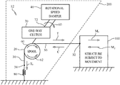
- FIG. 1 is a top-level schematic view of a damping system for structures in accordance with present invention
- FIG. 2 is a schematic view of a damping system for structures in accordance with an embodiment of the present invention
- FIG. 4 is a perspective view of a damping system using linear dampers in accordance with another embodiment of the present invention.
- Damping system 10 cooperates between two existing structures 100 and 200 , neither of which is part of the present invention.
- structure 100 is one that is subject to undesirable or unwanted movement that could be caused by changes in the environment or changes that are man-made without departing from the scope of the present invention.
- Structure 200 is one that is not subject to the unwanted movement such that it can serve as a supporting ground for parts of damping system 10 as will be explained further below.
- Damping system 10 includes a spool 20 , a flexible line 30 , a rotational speed damper 40 , and a slack-line prevention device 50 .
- Spool 20 , damper 40 , and slack-line prevention device 50 are supported/mounted on structure 200 .
- Line 30 is coupled on one end 32 to structure 100 , and is coupled on its other end 34 to slack-line prevention device 50 .
- Line 30 is wound around spool 20 .
- Rotational speed damper 40 is any device or mechanism capable of slowing the rotational speed of spool 20 .
- damper 40 engages with spool 20 to slow or damp the rotational speed thereof when line 30 is placed in tension causing spool 20 to rotate as indicated by arrow 60 .
- Line 30 is placed in tension “T” whenever structure 100 experiences movement “M 1 ” that pulls on end 32 of line 30 to thereby place line 30 in tension T.
- damper 40 disengages from spool 30 when line 30 is placed in compression “C” whenever structure 100 experiences movement “M 2 ” that pushes on end 32 of line 30 to thereby place line 30 in compression C.
- Spool 20 is able to rotate freely when disengaged from damper 40 .
- Slack-line prevention device 50 is any device or mechanism capable of applying a relatively small and constant tension force “T s ” to line 30 at its end 34 .
- Device 50 is configured to provide tension force T s that is exceeded whenever structure 100 experiences movement M 1 , and that can act on line 30 to remove all slack therein when structure 100 experiences movement M 2 . Since spool 20 is disengaged from damper 40 during movement M 2 , tension force T s will cause spool 20 to rotate in direction 62 that is opposite to direction 60 .
- Device 50 can be realized using one or more springs, weights, or combinations thereof without departing from the scope of the present invention.
- FIG. 2 illustrates an embodiment of the present invention's damping system and is referenced generally by numeral 12 .
- the above-described spool 20 and damper 40 are coupled together by a one-way clutch 70 and a rotatable shaft 72 .
- clutch 70 is coupled to spool 20 and shaft 72 such that clutch 70 engages with shaft 72 when the spool is rotating in direction 60 and disengages from shaft 72 when spool is rotating in direction 62 . In this way, shaft 72 will rotate in direction 60 in correspondence with spool 20 .
- Shaft 72 is coupled to damper 40 .
- Damping system 12 includes a spring 80 for the above-described slack-line prevention device 50 .
- Spring 80 is coupled between end 34 of line 30 and structure 200 to apply the above-described constant tension force T s .
- FIG. 3 illustrates a damping system of the present invention constructed in accordance with the teachings presented in FIGS. 1 and 2 where damper 40 is a rotating viscus damper.
- damper 40 has a rotating wheel 42 fixedly coupled to shaft 72 for rotation therewith, and has a fixed annular resistor 44 that acts to slow the rotational speed of wheel 42 in proportion to the speed of wheel 42 .
- Annular resistor 44 can be realized by coulomb (dry) friction device, a magnetic resistance device, or other viscous damping devices known in the art.
- the above-described one-way clutch 70 can be a conventional roller clutch coupled between spool 20 and shaft 72 in ways known in the art.
- Annular resistor 44 is fixed to structure 200 as indicated schematically in FIG. 3 .
- FIG. 4 Another type of rotational speed damper 40 is illustrated in FIG. 4 where shaft 72 is coupled to damper 40 via crank arm 74 that rotates eccentrically with shaft 72 when it rotates in direction 60 as described above.
- the eccentric rotation of crank arm 74 is rotationally slowed by damper 40 that comprises a plurality of linear dampers 46 , each of which is coupled between crank arm 74 and structure 200 .
- damper 40 that comprises a plurality of linear dampers 46 , each of which is coupled between crank arm 74 and structure 200 .
- linear dampers 46 are extended or shortened by the eccentric rotating end of crank arm 74 .
- the linear dampers 46 provide a damping force proportional to their extension and compression velocity, and apply that damping force to crank arm 74 at its eccentrically rotating end.
- Linear dampers 46 can be oil or gas filled piston devices, gas cylinder devices, etc., without departing from the scope of the present invention.
Abstract
A damping system includes a spool about which a tension line is wound. The line's first end is coupled to a first structure subject to forces causing unwanted movement thereof. A damper is coupled to a second structure not subject to the unwanted movement of the first structure. The damper is coupled to the spool for engagement with the spool to slow a rotational speed thereof when the spool rotates in a first direction. The damper is disengaged from the spool when the spool rotates in a second direction in opposition to the first direction. A device, coupled to the line's second end and to the second structure, applies a tension force to the line's second end. The tension force is exceeded when the first structure moves to place the line in tension, and is not exceeded when the first structure moves to place the line in compression.
Description
The invention described herein was made in the performance of work under a NASA contract and by an employee of the United States Government and is subject to the provisions of Public Law 96-517 (35 U.S.C. § 202) and may be manufactured and used by or for the Government for governmental purposes without the payment of any royalties thereon or therefore.
This invention relates to damping systems. More specifically, the invention is a system that damps out unwanted movement of a structure undergoing dynamic movement using a tension element coupled to the structure.
There are a variety of structure arrangements where dynamic or cyclic deflection and/or vibration behavior between two structures can produce undesirable results. For example, the relationship between a rocket support tower and a rocket is one where some off-axis rocket dynamic deflection (e.g., due to wind) relative to its rigid support tower is allowable, but excessive relative dynamic deflection is problematic and/or destructive. While conventional springs and dampers can be used to control the unwanted movement, solutions using such devices can impose unwanted loads and/or be too large and bulky for the spatial constraints dictated by the environment.
Accordingly, it is an object of the present invention to provide a damping system for structures.
Another object of the present invention is to provide a damping system configurable for a variety of two-structure arrangements.
Still another object of the present invention is to provide a damping system for damping vibrations in one structure relative to another structure.
Yet another object of the present invention is to provide a spatially efficient damping system for damping unwanted vibrations in a first structure relative to a second structure that is not subject to the unwanted vibrations.
Other objects and advantages of the present invention will become more obvious hereinafter in the specification and drawings.
In accordance with the present invention, a damping system for structures includes a spool about which a line is wound. The line is one that exhibits rigidity in tension and flexibility in compression. The line's first end is coupled to a first structure subject to forces causing unwanted movement thereof. A damper is coupled to a second structure not subject to the unwanted movement of the first structure. The damper is coupled to the spool for engagement with the spool to slow a rotational speed thereof when the spool rotates in a first direction. The damper is disengaged from the spool when the spool rotates in a second direction in opposition to the first direction. A device, coupled to the second end of the line and to the second structure, applies a tension force to the second end of the line. The tension force is exceeded when the first structure moves to place the line in tension, and is not exceeded when the first structure moves to place the line in compression.
Other objects, features and advantages of the present invention will become apparent upon reference to the following description of the preferred embodiments and to the drawings, wherein corresponding reference characters indicate corresponding parts throughout the several views of the drawings and wherein:
Referring now to the drawings and more particularly to FIG. 1 , a damping system for structures in accordance with the present invention is shown and is referenced generally by numeral 10. Damping system 10 cooperates between two existing structures 100 and 200, neither of which is part of the present invention. In general, structure 100 is one that is subject to undesirable or unwanted movement that could be caused by changes in the environment or changes that are man-made without departing from the scope of the present invention. Structure 200 is one that is not subject to the unwanted movement such that it can serve as a supporting ground for parts of damping system 10 as will be explained further below. Real-world examples of arrangements using structure 100/structure 200 include, but are not limited to, a rocket and its supporting tower, a boat/ship mast and its boat/ship, a free-standing tower and the ground on which it is mounted, aircraft wings and the aircraft's fuselage, etc.
Spool 20 is generally a cylindrical body around which line 30 is wound or wrapped. The surface of spool 20 that engages with line 30 can be flat or helically grooved (i.e. to resemble annular threads) such that the line 30 rests in the helical groove. The turns of line 30 wrapped around spool 20 should be in a single layer to prevent line 30 from wrapping on itself. That is, each turn of line 30 around spool 20 radially engages spool 20 but does not radially engage another turn of line 30. The number of turns of line 30 on spool 20 is chosen to support the tension load given the coefficient of friction between line 30 and spool 20.
Slack-line prevention device 50 is any device or mechanism capable of applying a relatively small and constant tension force “Ts” to line 30 at its end 34. Device 50 is configured to provide tension force Ts that is exceeded whenever structure 100 experiences movement M1, and that can act on line 30 to remove all slack therein when structure 100 experiences movement M2. Since spool 20 is disengaged from damper 40 during movement M2, tension force Ts will cause spool 20 to rotate in direction 62 that is opposite to direction 60. Device 50 can be realized using one or more springs, weights, or combinations thereof without departing from the scope of the present invention.
In operation, when structures 100 and 200 move away from one another, i.e., causing movement M1, line 30 is pulled at end 32 and is placed in tension T that exceeds tension force Ts thereby causing spool 20 to rotate in direction 60. As spool 20 rotates in direction 60, damper 40 is engaged to slow the rotational speed of spool 20, thereby damping movement M2. When structures 100 and 200 move towards one another, i.e., causing movement M2, line 30 is placed in compression C at end 32 such that tension force Ts causes spool 20 to rotate in direction 62 such that spool 20 is disengaged from damper 40. The above-described operation repeats in a cyclical fashion as structures 100 and 200 experience dynamic or cyclical movement away and towards one another.
As mentioned above, a variety of devices and/or mechanisms could be combined to provide the unique damping system of the present invention. By way of a non-limiting example, FIG. 2 illustrates an embodiment of the present invention's damping system and is referenced generally by numeral 12. In system 12, the above-described spool 20 and damper 40 are coupled together by a one-way clutch 70 and a rotatable shaft 72. More specifically, clutch 70 is coupled to spool 20 and shaft 72 such that clutch 70 engages with shaft 72 when the spool is rotating in direction 60 and disengages from shaft 72 when spool is rotating in direction 62. In this way, shaft 72 will rotate in direction 60 in correspondence with spool 20. Shaft 72 is coupled to damper 40. Accordingly, damper 40 slows the rotational speed of shaft 72 and spool 20 when both are rotating in direction 60. Damping system 12 includes a spring 80 for the above-described slack-line prevention device 50. Spring 80 is coupled between end 34 of line 30 and structure 200 to apply the above-described constant tension force Ts.
As mentioned above, the present invention can be realized with different types of rotational speed dampers. For example, FIG. 3 illustrates a damping system of the present invention constructed in accordance with the teachings presented in FIGS. 1 and 2 where damper 40 is a rotating viscus damper. In this embodiment, damper 40 has a rotating wheel 42 fixedly coupled to shaft 72 for rotation therewith, and has a fixed annular resistor 44 that acts to slow the rotational speed of wheel 42 in proportion to the speed of wheel 42. Annular resistor 44 can be realized by coulomb (dry) friction device, a magnetic resistance device, or other viscous damping devices known in the art. The above-described one-way clutch 70 can be a conventional roller clutch coupled between spool 20 and shaft 72 in ways known in the art. Annular resistor 44 is fixed to structure 200 as indicated schematically in FIG. 3 .
Another type of rotational speed damper 40 is illustrated in FIG. 4 where shaft 72 is coupled to damper 40 via crank arm 74 that rotates eccentrically with shaft 72 when it rotates in direction 60 as described above. The eccentric rotation of crank arm 74 is rotationally slowed by damper 40 that comprises a plurality of linear dampers 46, each of which is coupled between crank arm 74 and structure 200. As crank arm 74 is turned by shaft 72, linear dampers 46 are extended or shortened by the eccentric rotating end of crank arm 74. The linear dampers 46 provide a damping force proportional to their extension and compression velocity, and apply that damping force to crank arm 74 at its eccentrically rotating end. Linear dampers 46 can be oil or gas filled piston devices, gas cylinder devices, etc., without departing from the scope of the present invention.
The advantages of the present invention are numerous. The present invention applies a tension-activated, speed-dependent damping force to damp movement in one direction of a dynamic system. Applying the damping force in tension only allows the system to use simple and relatively lightweight tension elements that are readily available in highly efficient forms. Further, by only requiring a simple attachment point to a moving structure, the present invention minimizes any location and/or orientation requirements in a given application. The present invention's application of a relatively small slack-line-prevention tension can be implemented with a variety of simple devices/mechanisms to further contribute to the system's simplicity and reliability.
Although the invention has been described relative to a specific embodiment thereof, there are numerous variations and modifications that will be readily apparent to those skilled in the art in light of the above teachings. For example, the present invention could incorporate a transmission mechanism between the system's spool and damper that increases or decreases the damper's input rotation rate relative to that of the spool. It is therefore to be understood that, within the scope of the appended claims, the invention may be practiced other than as specifically described.
Claims (10)
1. A damping system for structures, comprising:
a spool;
a line for exhibiting rigidity in tension and flexibility in compression, said line including a first end adapted to be coupled to a first structure subject to forces causing unwanted movement thereof, said line wound around said spool and extending to a second end of said line;
a one-way clutch coupled to said spool for rotation therewith;
a shaft coupled to said clutch wherein said shaft is engaged for rotation therewith when said spool and said clutch rotate in a first direction as caused by said line being in tension, and wherein said shaft is disengaged from said clutch when said spool and said clutch rotate in a second direction in opposition to said first direction as caused by said line being in compression;
a damper coupled to said shaft for slowing rotational speed of said shaft rotating in said first direction; and
a spring coupled to said second end of said line and adapted to be coupled to a second structure not subject to the unwanted movement of the first structure, said spring applying a tension force to said second end of said line, wherein said tension force is exceeded when the first structure moves to place said line in tension, and wherein said tension force is not exceeded when the first structure moves to place said line in compression.
2. A damping system as in claim 1 , wherein said damper comprises a rotating damper.
3. A damping system for structures, comprising:
a spool;
a line for exhibiting rigidity in tension and flexibility in compression, said line including a first end adapted to be coupled to a first structure subject to forces causing unwanted movement thereof, said line wound around said spool and extending to a second end of said line;
a one-way clutch coupled to said spool for rotation therewith;
a shaft coupled to said clutch wherein said shaft is engaged for rotation therewith when said spool and said clutch rotate in a first direction, and wherein said shaft is disengaged from said clutch when said spool and said clutch rotate in a second direction in opposition to said first direction;
a damper coupled to said shaft for slowing rotational speed of said shaft rotating in said first direction, wherein said damper comprises a plurality of linear dampers; and
a spring coupled to said second end of said line and adapted to be coupled to a second structure not subject to the unwanted movement of the first structure, said spring applying a tension force to said second end of said line, wherein said tension force is exceeded when the first structure moves to place said line in tension, and wherein said tension force is not exceeded when the first structure moves to place said line in compression.
4. A damping system as in claim 3 , further comprising a support structure coupled to said shaft for supporting said rotation thereof, said support structure being isolated from the unwanted movement of the first structure.
5. A damping system as in claim 3 , wherein said line is wound around said spool in a single-layer wrap.
6. A damping system for structures, comprising:
a spool;
a line for exhibiting rigidity in tension and flexibility in compression, said line including a first end adapted to be coupled to a first structure subject to forces causing unwanted movement thereof, said line wound around said spool and extending to a second end of said line;
a damper adapted to be coupled to a second structure not subject to the unwanted movement of the first structure, said damper coupled to said spool for engagement with said spool to slow a rotational speed thereof when said spool rotates in a first direction and for disengagement from said spool when said spool rotates in a second direction in opposition to said first direction, wherein said damper comprises a plurality of linear dampers; and
a device coupled to said second end of said line and adapted to be coupled to the second structure, said device applying a tension force to said second end of said line, wherein said tension force is exceeded when the first structure moves to place said line in tension, and wherein said tension force is not exceeded when the first structure moves to place said line in compression.
7. A damping system as in claim 6 , wherein said line is wound around said spool in a single-layer wrap.
8. A damping system as in claim 6 , wherein said device comprises a spring.
9. A damping system for structures, comprising:
a spool;
a line for exhibiting rigidity in tension and flexibility in compression, said line including a first end adapted to be coupled to a first structure subject to forces causing unwanted movement thereof, said line wound around said spool and extending to a second end of said line;
a one-way clutch coupled to said spool for rotation therewith;
a shaft adapted to be mechanically and rotationally supported at a second structure not subject to the unwanted movement, said shaft coupled to said clutch wherein said shaft is engaged for rotation therewith when said spool and said clutch rotate in a first direction, and wherein said shaft is disengaged from said clutch when said spool and said clutch rotate in a second direction in opposition to said first direction;
a damper coupled to said shaft for slowing rotational speed of said shaft rotating in said first direction, wherein said damper comprises a plurality of linear dampers; and
a spring coupled to said second end of said line and adapted to be coupled to a second structure not subject to the unwanted movement of the first structure, said spring applying a constant tension force to said second end of said line, wherein said constant tension force is exceeded when the first structure moves to place said line in tension, and wherein said constant tension force is not exceeded when the first structure moves to place said line in compression.
10. A damping system as in claim 9 , wherein said line is wound around said spool in a single-layer wrap.
Priority Applications (1)
| Application Number | Priority Date | Filing Date | Title |
|---|---|---|---|
| US17/063,319 US11078984B1 (en) | 2020-10-05 | 2020-10-05 | Structure movement damping system using tension element |
Applications Claiming Priority (1)
| Application Number | Priority Date | Filing Date | Title |
|---|---|---|---|
| US17/063,319 US11078984B1 (en) | 2020-10-05 | 2020-10-05 | Structure movement damping system using tension element |
Publications (1)
| Publication Number | Publication Date |
|---|---|
| US11078984B1 true US11078984B1 (en) | 2021-08-03 |
Family
ID=77063540
Family Applications (1)
| Application Number | Title | Priority Date | Filing Date |
|---|---|---|---|
| US17/063,319 Active US11078984B1 (en) | 2020-10-05 | 2020-10-05 | Structure movement damping system using tension element |
Country Status (1)
| Country | Link |
|---|---|
| US (1) | US11078984B1 (en) |
Cited By (1)
| Publication number | Priority date | Publication date | Assignee | Title |
|---|---|---|---|---|
| US11441311B1 (en) * | 2021-03-31 | 2022-09-13 | United States Of America As Represented By The Administrator Of Nasa | Dynamics management system for a structure using tension and resistance elements |
Citations (13)
| Publication number | Priority date | Publication date | Assignee | Title |
|---|---|---|---|---|
| US3043566A (en) * | 1958-08-14 | 1962-07-10 | Lionel Grise Jr | Control apparatus for power-operated cables |
| US3360225A (en) * | 1963-04-11 | 1967-12-26 | Camossi Carlo | Process for manufacturing isolators of shock absorbers based on the principle of damping vibrations and/or shocks by means of multistrand cables |
| US3371895A (en) * | 1965-12-27 | 1968-03-05 | Aeroflex Lab Inc | Vibration-damping and loadsupporting apparatus |
| US3946976A (en) * | 1973-06-05 | 1976-03-30 | Barry Wright Corporation | Means for resiliently supporting a body |
| US4846446A (en) | 1982-04-30 | 1989-07-11 | Lockheed Corporation | Rope tension damper |
| US6086007A (en) | 1998-06-01 | 2000-07-11 | Ericsson Inc. | Viscously damped cord retract |
| DE10309825A1 (en) * | 2003-03-05 | 2004-09-16 | Bosch Rexroth Ag | Wind generator installation with mast provided with stay wires has vibration dampers fitted in stay wires |
| US7371199B2 (en) | 2003-09-13 | 2008-05-13 | Dayco Products, Llc | One-way clutched damper for automatic belt tensioner |
| US20130341453A1 (en) * | 2011-03-23 | 2013-12-26 | Flamek Ltd | Device for tightening rope |
| US9475673B2 (en) | 2011-01-07 | 2016-10-25 | Crestron Electronics, Inc. | Cable retractor |
| DE102018100868B3 (en) * | 2018-01-16 | 2019-02-21 | Nordex Energy Gmbh | Method and device for damping tower vibrations in a wind turbine and tower with such a device |
| US20190276284A1 (en) * | 2018-03-07 | 2019-09-12 | Jeffrey Edward Robb | Cable tensioning device |
| US20200355166A1 (en) * | 2017-09-04 | 2020-11-12 | Mhi Vestas Offshore Wind A/S | Tower vibration damper |
-
2020
- 2020-10-05 US US17/063,319 patent/US11078984B1/en active Active
Patent Citations (13)
| Publication number | Priority date | Publication date | Assignee | Title |
|---|---|---|---|---|
| US3043566A (en) * | 1958-08-14 | 1962-07-10 | Lionel Grise Jr | Control apparatus for power-operated cables |
| US3360225A (en) * | 1963-04-11 | 1967-12-26 | Camossi Carlo | Process for manufacturing isolators of shock absorbers based on the principle of damping vibrations and/or shocks by means of multistrand cables |
| US3371895A (en) * | 1965-12-27 | 1968-03-05 | Aeroflex Lab Inc | Vibration-damping and loadsupporting apparatus |
| US3946976A (en) * | 1973-06-05 | 1976-03-30 | Barry Wright Corporation | Means for resiliently supporting a body |
| US4846446A (en) | 1982-04-30 | 1989-07-11 | Lockheed Corporation | Rope tension damper |
| US6086007A (en) | 1998-06-01 | 2000-07-11 | Ericsson Inc. | Viscously damped cord retract |
| DE10309825A1 (en) * | 2003-03-05 | 2004-09-16 | Bosch Rexroth Ag | Wind generator installation with mast provided with stay wires has vibration dampers fitted in stay wires |
| US7371199B2 (en) | 2003-09-13 | 2008-05-13 | Dayco Products, Llc | One-way clutched damper for automatic belt tensioner |
| US9475673B2 (en) | 2011-01-07 | 2016-10-25 | Crestron Electronics, Inc. | Cable retractor |
| US20130341453A1 (en) * | 2011-03-23 | 2013-12-26 | Flamek Ltd | Device for tightening rope |
| US20200355166A1 (en) * | 2017-09-04 | 2020-11-12 | Mhi Vestas Offshore Wind A/S | Tower vibration damper |
| DE102018100868B3 (en) * | 2018-01-16 | 2019-02-21 | Nordex Energy Gmbh | Method and device for damping tower vibrations in a wind turbine and tower with such a device |
| US20190276284A1 (en) * | 2018-03-07 | 2019-09-12 | Jeffrey Edward Robb | Cable tensioning device |
Cited By (1)
| Publication number | Priority date | Publication date | Assignee | Title |
|---|---|---|---|---|
| US11441311B1 (en) * | 2021-03-31 | 2022-09-13 | United States Of America As Represented By The Administrator Of Nasa | Dynamics management system for a structure using tension and resistance elements |
Similar Documents
| Publication | Publication Date | Title |
|---|---|---|
| US8192312B2 (en) | Isolator with damping | |
| US11078984B1 (en) | Structure movement damping system using tension element | |
| US9097335B2 (en) | Crankshaft isolating decoupler | |
| US9206892B2 (en) | Isolating decoupler | |
| JP5357558B2 (en) | Control moment gyro | |
| US20170097068A1 (en) | Overrunning alternator decoupling pulley design | |
| EP2770225A1 (en) | Damping device | |
| US10619699B2 (en) | Self-turning compact vibration damper | |
| US11441311B1 (en) | Dynamics management system for a structure using tension and resistance elements | |
| US4333553A (en) | Prestressed elastomer for energy storage | |
| GB2046874A (en) | Energy storage device | |
| US20120167344A1 (en) | Shock-absorber device | |
| US4287969A (en) | Motion snubbing device | |
| JP2005009565A (en) | Vibration damping apparatus | |
| RU2313014C1 (en) | Shock absorber | |
| EP2450592A2 (en) | Dampening device | |
| US4796862A (en) | Winch compensator | |
| WO2016178892A1 (en) | Flat spring torsional vibration dampers and absorbers | |
| US1826172A (en) | Power transmitting device | |
| US1085443A (en) | Damping torsional vibrations in crank-shafts. | |
| US3706230A (en) | Rotary actuator | |
| US5315888A (en) | Gyro nutation damper | |
| JP2970479B2 (en) | Damping device | |
| US1778641A (en) | Vibration damper | |
| JP5684272B2 (en) | Vibration damper device for drive system |
Legal Events
| Date | Code | Title | Description |
|---|---|---|---|
| FEPP | Fee payment procedure |
Free format text: ENTITY STATUS SET TO UNDISCOUNTED (ORIGINAL EVENT CODE: BIG.); ENTITY STATUS OF PATENT OWNER: LARGE ENTITY |
|
| STCF | Information on status: patent grant |
Free format text: PATENTED CASE |