US11073568B2 - Electronic device and state determination method of electronic device - Google Patents
Electronic device and state determination method of electronic device Download PDFInfo
- Publication number
- US11073568B2 US11073568B2 US16/782,482 US202016782482A US11073568B2 US 11073568 B2 US11073568 B2 US 11073568B2 US 202016782482 A US202016782482 A US 202016782482A US 11073568 B2 US11073568 B2 US 11073568B2
- Authority
- US
- United States
- Prior art keywords
- secondary battery
- amount
- state
- discharge amount
- total charge
- Prior art date
- Legal status (The legal status is an assumption and is not a legal conclusion. Google has not performed a legal analysis and makes no representation as to the accuracy of the status listed.)
- Active
Links
Images


Classifications
-
- H—ELECTRICITY
- H01—ELECTRIC ELEMENTS
- H01M—PROCESSES OR MEANS, e.g. BATTERIES, FOR THE DIRECT CONVERSION OF CHEMICAL ENERGY INTO ELECTRICAL ENERGY
- H01M10/00—Secondary cells; Manufacture thereof
- H01M10/42—Methods or arrangements for servicing or maintenance of secondary cells or secondary half-cells
- H01M10/425—Structural combination with electronic components, e.g. electronic circuits integrated to the outside of the casing
-
- H—ELECTRICITY
- H04—ELECTRIC COMMUNICATION TECHNIQUE
- H04M—TELEPHONIC COMMUNICATION
- H04M1/00—Substation equipment, e.g. for use by subscribers
- H04M1/72—Mobile telephones; Cordless telephones, i.e. devices for establishing wireless links to base stations without route selection
- H04M1/724—User interfaces specially adapted for cordless or mobile telephones
- H04M1/72448—User interfaces specially adapted for cordless or mobile telephones with means for adapting the functionality of the device according to specific conditions
- H04M1/72454—User interfaces specially adapted for cordless or mobile telephones with means for adapting the functionality of the device according to specific conditions according to context-related or environment-related conditions
-
- G—PHYSICS
- G01—MEASURING; TESTING
- G01R—MEASURING ELECTRIC VARIABLES; MEASURING MAGNETIC VARIABLES
- G01R31/00—Arrangements for testing electric properties; Arrangements for locating electric faults; Arrangements for electrical testing characterised by what is being tested not provided for elsewhere
- G01R31/36—Arrangements for testing, measuring or monitoring the electrical condition of accumulators or electric batteries, e.g. capacity or state of charge [SoC]
- G01R31/392—Determining battery ageing or deterioration, e.g. state of health
-
- G—PHYSICS
- G01—MEASURING; TESTING
- G01R—MEASURING ELECTRIC VARIABLES; MEASURING MAGNETIC VARIABLES
- G01R31/00—Arrangements for testing electric properties; Arrangements for locating electric faults; Arrangements for electrical testing characterised by what is being tested not provided for elsewhere
- G01R31/36—Arrangements for testing, measuring or monitoring the electrical condition of accumulators or electric batteries, e.g. capacity or state of charge [SoC]
- G01R31/382—Arrangements for monitoring battery or accumulator variables, e.g. SoC
-
- G—PHYSICS
- G01—MEASURING; TESTING
- G01R—MEASURING ELECTRIC VARIABLES; MEASURING MAGNETIC VARIABLES
- G01R31/00—Arrangements for testing electric properties; Arrangements for locating electric faults; Arrangements for electrical testing characterised by what is being tested not provided for elsewhere
- G01R31/36—Arrangements for testing, measuring or monitoring the electrical condition of accumulators or electric batteries, e.g. capacity or state of charge [SoC]
- G01R31/3644—Constructional arrangements
- G01R31/3646—Constructional arrangements for indicating electrical conditions or variables, e.g. visual or audible indicators
-
- G—PHYSICS
- G01—MEASURING; TESTING
- G01R—MEASURING ELECTRIC VARIABLES; MEASURING MAGNETIC VARIABLES
- G01R31/00—Arrangements for testing electric properties; Arrangements for locating electric faults; Arrangements for electrical testing characterised by what is being tested not provided for elsewhere
- G01R31/36—Arrangements for testing, measuring or monitoring the electrical condition of accumulators or electric batteries, e.g. capacity or state of charge [SoC]
- G01R31/367—Software therefor, e.g. for battery testing using modelling or look-up tables
-
- H—ELECTRICITY
- H01—ELECTRIC ELEMENTS
- H01M—PROCESSES OR MEANS, e.g. BATTERIES, FOR THE DIRECT CONVERSION OF CHEMICAL ENERGY INTO ELECTRICAL ENERGY
- H01M10/00—Secondary cells; Manufacture thereof
- H01M10/42—Methods or arrangements for servicing or maintenance of secondary cells or secondary half-cells
- H01M10/4285—Testing apparatus
-
- H—ELECTRICITY
- H01—ELECTRIC ELEMENTS
- H01M—PROCESSES OR MEANS, e.g. BATTERIES, FOR THE DIRECT CONVERSION OF CHEMICAL ENERGY INTO ELECTRICAL ENERGY
- H01M10/00—Secondary cells; Manufacture thereof
- H01M10/42—Methods or arrangements for servicing or maintenance of secondary cells or secondary half-cells
- H01M10/44—Methods for charging or discharging
-
- H—ELECTRICITY
- H01—ELECTRIC ELEMENTS
- H01M—PROCESSES OR MEANS, e.g. BATTERIES, FOR THE DIRECT CONVERSION OF CHEMICAL ENERGY INTO ELECTRICAL ENERGY
- H01M10/00—Secondary cells; Manufacture thereof
- H01M10/42—Methods or arrangements for servicing or maintenance of secondary cells or secondary half-cells
- H01M10/48—Accumulators combined with arrangements for measuring, testing or indicating the condition of cells, e.g. the level or density of the electrolyte
-
- H—ELECTRICITY
- H02—GENERATION; CONVERSION OR DISTRIBUTION OF ELECTRIC POWER
- H02J—ELECTRIC POWER NETWORKS; CIRCUIT ARRANGEMENTS OR SYSTEMS FOR SUPPLYING OR DISTRIBUTING ELECTRIC POWER; SYSTEMS FOR STORING ELECTRIC ENERGY
- H02J7/00—Circuit arrangements for charging or discharging batteries or for supplying loads from batteries
- H02J7/80—Circuit arrangements for charging or discharging batteries or for supplying loads from batteries including monitoring or indicating arrangements
- H02J7/84—Control of state of health [SOH]
-
- G—PHYSICS
- G01—MEASURING; TESTING
- G01R—MEASURING ELECTRIC VARIABLES; MEASURING MAGNETIC VARIABLES
- G01R31/00—Arrangements for testing electric properties; Arrangements for locating electric faults; Arrangements for electrical testing characterised by what is being tested not provided for elsewhere
- G01R31/36—Arrangements for testing, measuring or monitoring the electrical condition of accumulators or electric batteries, e.g. capacity or state of charge [SoC]
- G01R31/382—Arrangements for monitoring battery or accumulator variables, e.g. SoC
- G01R31/3828—Arrangements for monitoring battery or accumulator variables, e.g. SoC using current integration
-
- H—ELECTRICITY
- H01—ELECTRIC ELEMENTS
- H01M—PROCESSES OR MEANS, e.g. BATTERIES, FOR THE DIRECT CONVERSION OF CHEMICAL ENERGY INTO ELECTRICAL ENERGY
- H01M10/00—Secondary cells; Manufacture thereof
- H01M10/42—Methods or arrangements for servicing or maintenance of secondary cells or secondary half-cells
- H01M10/425—Structural combination with electronic components, e.g. electronic circuits integrated to the outside of the casing
- H01M2010/4271—Battery management systems including electronic circuits, e.g. control of current or voltage to keep battery in healthy state, cell balancing
-
- H—ELECTRICITY
- H01—ELECTRIC ELEMENTS
- H01M—PROCESSES OR MEANS, e.g. BATTERIES, FOR THE DIRECT CONVERSION OF CHEMICAL ENERGY INTO ELECTRICAL ENERGY
- H01M10/00—Secondary cells; Manufacture thereof
- H01M10/42—Methods or arrangements for servicing or maintenance of secondary cells or secondary half-cells
- H01M10/425—Structural combination with electronic components, e.g. electronic circuits integrated to the outside of the casing
- H01M2010/4278—Systems for data transfer from batteries, e.g. transfer of battery parameters to a controller, data transferred between battery controller and main controller
-
- H—ELECTRICITY
- H04—ELECTRIC COMMUNICATION TECHNIQUE
- H04M—TELEPHONIC COMMUNICATION
- H04M2201/00—Electronic components, circuits, software, systems or apparatus used in telephone systems
- H04M2201/34—Microprocessors
-
- H—ELECTRICITY
- H04—ELECTRIC COMMUNICATION TECHNIQUE
- H04M—TELEPHONIC COMMUNICATION
- H04M2250/00—Details of telephonic subscriber devices
- H04M2250/12—Details of telephonic subscriber devices including a sensor for measuring a physical value, e.g. temperature or motion
-
- Y—GENERAL TAGGING OF NEW TECHNOLOGICAL DEVELOPMENTS; GENERAL TAGGING OF CROSS-SECTIONAL TECHNOLOGIES SPANNING OVER SEVERAL SECTIONS OF THE IPC; TECHNICAL SUBJECTS COVERED BY FORMER USPC CROSS-REFERENCE ART COLLECTIONS [XRACs] AND DIGESTS
- Y02—TECHNOLOGIES OR APPLICATIONS FOR MITIGATION OR ADAPTATION AGAINST CLIMATE CHANGE
- Y02E—REDUCTION OF GREENHOUSE GAS [GHG] EMISSIONS, RELATED TO ENERGY GENERATION, TRANSMISSION OR DISTRIBUTION
- Y02E60/00—Enabling technologies; Technologies with a potential or indirect contribution to GHG emissions mitigation
- Y02E60/10—Energy storage using batteries
Definitions
- the present invention relates to an electronic device and a method for determining a status of the electronic device.
- Lithium-ion batteries are widely used in electronic devices such as smartphones, but they are known to degrade gradually during use. As lithium-ion batteries deteriorate, internal pressure increases and expansion are evident due to internal stack expansion caused by charging/discharging, and due to electrolyte vaporization caused by increase in internal temperature. If these lithium-ion batteries are left in a degraded state, there is a risk of ignition or explosion.
- lithium-ion batteries can easily become hazardous due to minor reasons.
- Patent Document 1 does not alert the user until the pressure of the lithium-ion battery reaches a threshold set by the manufacturer because the detected pressure is compared with a predetermined threshold. That is, even if a sign of a dangerous state appears, no warning will be given until the lithium-ion battery actually reaches a dangerous state.
- the related art provides warnings and the like after a lithium-ion battery actually reaches a dangerous state, and it is impossible to give warning and the like beforehand until the lithium-ion battery reaches a dangerous state.
- Patent Document 1 Japanese Patent No. 5573169
- Patent Document 2 Japanese Laid-open Patent Application Publication No. 08-331769
- an electronic device including a deformation amount detecting unit configured to detect a deformation amount of a secondary battery connected to the electronic device; a total charge/discharge amount detecting unit configured to detect a total charge/discharge amount of the secondary battery; a storage unit configured to store reference data representing a relationship between the deformation amount and the total charge/discharge amount; a state determining unit configured to determine a state of the secondary battery, based on the deformation amount detected by the deformation amount detecting unit, the total charge/discharge amount detected by the total charge/discharge amount detecting unit, and the reference data; and a notification control unit configured to perform a notification based on a result of the state of the secondary battery.
- FIG. 1 is a block diagram illustrating a schematic configuration of an electronic device according to a first embodiment
- FIG. 2 is a diagram illustrating a lithium-ion battery to which a strain detecting unit is attached;
- FIG. 3 is a diagram illustrating a reference value, a threshold value, and an upper limit value stored in a storage unit
- FIG. 4 is a flowchart illustrating a process flow of a state determination process performed by a state determining unit
- FIG. 5 is a diagram illustrating examples of measured results of a deformation amount
- FIG. 6 is a diagram illustrating an example of a message displayed on a display unit
- FIG. 7 is a diagram illustrating another example of a message displayed on the display unit.
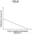
- FIG. 8 is a diagram illustrating an example of a threshold value depending on a total charge/discharge amount
- FIG. 9 is a flowchart illustrating a process flow of the state determination process according to a second embodiment
- FIG. 10 is a diagram illustrating variations in deformation amount depending on individual differences in batteries
- FIG. 11 is a diagram illustrating an example of a threshold value depending on the total charge/discharge amount
- FIG. 12 is a flowchart illustrating a process flow of the state determination process according to a third embodiment
- FIG. 13 is a diagram illustrating an example of a threshold value depending on the total charge/discharge amount
- FIG. 14 is a diagram illustrating a schematic configuration of an electronic device according to a fourth embodiment
- FIG. 15 is a flowchart illustrating a process flow of a state predicting process performed by a state predicting unit
- FIG. 16 is a diagram explaining a concept of a calculation method of X 1 and X 2 based on functions f(X) and g(X);
- FIG. 17 is a diagram illustrating an example of a message displayed on the display unit
- FIG. 18 is a diagram explaining a concept of a calculation method of X 1 and X 2 according to a fifth embodiment
- FIG. 19 is a diagram explaining a concept of a calculation method of X 1 and X 2 according to a sixth embodiment
- FIG. 20 is a flowchart illustrating an example of a notification method when results of state determination and state prediction are notified
- FIGS. 21A and 21B illustrate other notification examples of a result of state prediction
- FIG. 22A and FIG. 22B illustrate examples of notifications that are notified in addition to a result of state prediction
- FIG. 23 is a flowchart illustrating a full charge detecting process
- FIG. 24 is a graph illustrating a charging characteristic of the lithium-ion battery.
- FIG. 25 is a flowchart illustrating a stable state detecting process.
- a smartphone is illustrated as an example of an electronic device to which the present invention is applied.
- FIG. 1 is a diagram illustrating a schematic configuration of the electronic device 100 according to the first embodiment.
- the electronic device 100 includes a main body 200 and a battery section 300 as a battery module.
- a charger 400 is connected to the battery section 300 .
- the main body 200 includes a touch panel display 201 , an operation button 202 , a communication unit 203 , a speaker 204 , a microphone 205 , a CPU (Central Processing Unit) 206 , a storage unit 207 , a charge control unit 209 , a lamp 210 , and a vibrator 211 .
- a touch panel display 201 an operation button 202 , a communication unit 203 , a speaker 204 , a microphone 205 , a CPU (Central Processing Unit) 206 , a storage unit 207 , a charge control unit 209 , a lamp 210 , and a vibrator 211 .
- a touch panel display 201 includes a touch panel display 201 , an operation button 202 , a communication unit 203 , a speaker 204 , a microphone 205 , a CPU (Central Processing Unit) 206 , a storage unit 207 , a charge control unit 209 , a lamp 210
- the touch panel display 201 includes a display unit 201 a and a touch panel 201 b .
- the display unit 201 a is overlaid with the touch panel 201 b.
- the display unit 201 a may be a display device such as a liquid crystal display or an organic EL display.
- a detection method of the touch panel 201 b may be any types of methods, such as a capacitive method, a resistive method, a surface acoustic wave method, an infrared method, and a load detection method.
- the operation button 202 is a button that accepts an operation input from a user.
- Examples of the operation button 202 include a power button and a volume button.
- the communication unit 203 is, for example, a wireless communication module that performs radio communication.
- the communication unit 203 supports communication standards such as 2G, 3G, 4G, and 5G, or short-range radio communication standards.
- the speaker 204 outputs a sound signal sent from the CPU 206 as a sound.
- the speaker 204 outputs, for example, voice or music of video content played back on the electronic device 100 , and voice of the other person on the phone.
- the microphone 205 converts the user's voice or the like that is captured by the microphone 205 into a sound signal, and transmits the sound signal to the CPU 206 .
- the CPU 206 is a main control unit that controls each portion of the main body 200 and the battery section 300 .
- the CPU 206 executes instructions included in a program (computer program) stored in the storage unit 207 while referring to data stored in the storage unit 207 as necessary.
- the CPU 206 implements various functions based on the data and the instructions.
- the storage unit 207 includes a memory such as a RAM (Random Access Memory) or a flash memory.
- the storage unit 207 stores various types of data such as setting data and detected data, and programs.
- the charge control unit 209 is connected to a positive terminal and a negative terminal of the battery section 300 , and controls the charger 400 based on voltage and current of the battery section 300 , to charge a lithium-ion battery 301 .
- the lamp 210 is a light source such as a light emitting diode (LED), and provides a notification such as a charging status of the lithium-ion battery 301 and a warning, based on control by the CPU 206 .
- LED light emitting diode
- the vibrator 211 is a vibration motor that vibrates in accordance with control by the CPU 206 , and vibrates when, for example, notifying a warning or the like.
- the battery section 300 includes the lithium-ion battery 301 , a strain detecting unit 302 , a voltage detecting unit 303 , a current detecting unit 304 , a temperature detecting unit 305 , a controller 306 , and a storage unit 307 .
- the lithium-ion battery 301 is a secondary battery (rechargeable battery) that is formed by connecting multiple cells.
- the lithium-ion battery 301 may be a secondary battery that consists of a single cell.
- the lithium-ion battery 301 supplies power to each element of the battery section 300 and to the main body 200 . That is, the main body 200 is a load device with respect to the lithium-ion battery 301 .
- the strain detecting unit 302 is a sensor that detects an amount of strain in the lithium-ion battery 301 .
- a strain gauge which detects strain occurring in an object to be measured as a change in electrical resistance, may be used as the strain detecting unit 302 .
- the change in the electrical resistance of the strain gauge is detected, for example, by converting the electrical resistance to voltage using a Wheatstone bridge.
- the strain detecting unit 302 is attached to the lithium-ion battery 301 with adhesive or the like. For example, as illustrated in FIG. 2 , if the lithium-ion battery 301 is flat, the strain detecting unit 302 is attached to a surface of the lithium-ion battery 301 .
- the strain detecting unit 302 is not limited to a strain gauge, and may be a pressure sensor.
- the voltage detecting unit 303 detects voltage between the terminals of the lithium-ion battery 301 , and outputs a detected value of the voltage (may also be referred to as a “voltage detection value”) to the controller 306 .
- a current detecting unit 304 is disposed, for example, on a charging path between the lithium-ion battery 301 and the charger 400 .
- the current detecting unit 304 has a detection resistor, and detects charging current and discharging current to output a detected value of the current (may also be referred to as a “current detection value”) to the controller 306 .
- the controller 306 controls each element in the battery section 300 .
- the controller 306 includes a processor (CPU), and the CPU executes instructions included in a program stored in the storage unit 307 while referring to data stored in the storage unit 307 as necessary.
- the controller 306 implements various functions based on the data and the instructions.
- the temperature detecting unit 305 is a temperature sensor that detects a temperature of the lithium-ion battery 301 or the surroundings of the lithium-ion battery 301 , and outputs the detected temperature value to the controller 306 .
- the storage unit 307 includes a memory such as a RAM or a flash memory.
- the storage unit 307 stores various types of data such as setting data and detected data, and programs.
- the controller 306 includes, for example, a full charge detecting unit 310 , a stability detecting unit 311 , a deformation amount detecting unit 312 , and a total charge/discharge amount detecting unit 313 .
- the full charge detecting unit 310 detects whether the lithium-ion battery 301 is fully charged, based on the voltage detection value detected by the voltage detecting unit 303 and the current detection value detected by the current detecting unit 304 .
- the output voltage of the lithium-ion battery 301 stabilizes.
- the output voltage of a battery just after full charge may be considered to be V 1 (charge voltage)
- the output voltage of the battery while an unloaded state or a load state of faint discharging continues may be considered to be V 2 (open end voltage).
- V 1 charge voltage
- V 2 open end voltage
- the stability detecting unit 311 detects whether or not the lithium-ion battery 301 is in a stable state, based on the voltage detection value detected by the voltage detecting unit 303 and the current detection value detected by the current detecting unit 304 .
- the deformation amount detecting unit 312 detects a deformation amount of the lithium-ion battery 301 from when use of the lithium-ion battery 301 is started, based on an amount of strain of the lithium-ion battery 301 detected by the strain detecting unit 302 .
- the deformation amount of the lithium-ion battery 301 from when use of the lithium-ion battery 301 is started is denoted by “P”.
- the deformation of the lithium-ion battery 301 is caused by expansion due to degradation, or by external pressure.
- the deformation amount P may be a value obtained by subtracting or averaging the strain value detected by the strain detecting unit 302 .
- the deformation amount P may be obtained by weighting to a value detected by the strain detecting unit 302 , based on a temperature detected by the temperature detecting unit 305 .
- the deformation amount detecting unit 312 periodically detects the deformation amount P, and records the deformation amount P into the storage unit 307 .
- the controller 306 receives, from the CPU 206 , a command to retrieve the deformation amount P, the controller 306 transmits the deformation amount P recorded in the storage unit 307 to the CPU 206 .
- the total charge/discharge amount detecting unit 313 detects a total charge/discharge amount C, which is a sum of an amount of charge that is discharged since use of the lithium-ion battery 301 was started and an amount of charge that is charged since the use of the lithium-ion battery 301 was started, based on a current detection value of charge current and a current detection value of discharge current that are input from the current detecting unit 304 to the controller 306 .
- the amount of charge that is discharged is the amount of electric charge calculated by integrating the current discharged from the lithium-ion battery 301 with respect to time
- the amount of charge that is charged is the amount of electric charge calculated by integrating the current charged to the lithium-ion battery 301 with respect to time.
- the amount of charge that is discharged and/or the amount of charge that is charged may be referred to as the charge/discharge amount.
- the total charge/discharge amount C may be treated as quantity of electricity, or may be replaced by a cycle count (i.e., the number of times of charge/discharge) that is conventionally used as a parameter indicating aging of a secondary battery.
- the total charge/discharge amount detecting unit 313 periodically detects the total charge/discharge amount C, and records the total charge/discharge amount C into the storage unit 307 .
- the controller 306 Upon receiving a command to retrieve the total charge/discharge amount C from the CPU 206 , the controller 306 transmits the total charge/discharge amount C recorded in the storage unit 307 to the CPU 206 .
- the CPU 206 includes, for example, a state determining unit 220 and a notification control unit 221 .
- the state determining unit 220 determines a state of the lithium-ion battery 301 based on a relationship between the total charge/discharge amount C of the lithium-ion battery 301 and the deformation amount P of the lithium-ion battery 301 .
- the notification control unit 221 controls the display unit 201 a , the speaker 204 , the lamp 210 , the vibrator 211 , and the like, to notify a user with a warning or the like.
- the notification control unit 221 may notify the user by displaying a message on the display unit 201 a , by voice notification using the speaker 204 , by blinking the lamp 210 , by vibration of the vibrator 211 , or the like.
- the state determining unit 220 performs determination using a reference value, a threshold value, an upper limit value, and the like stored in the storage unit 207 .
- FIG. 3 is a diagram illustrating the reference value P′, the threshold value Pth, and the upper limit value Pmax stored in the storage unit 207 .
- the reference value P′ represents the deformation amount P with respect to total charge/discharge amount C in an ideal lithium-ion battery.
- the deformation amount P of a lithium-ion battery does not monotonically increase with time.
- the deformation amount P increases during charging, and decreases during discharging.
- there is a correlation between total charge/discharge amount C and the deformation amount P and the deformation amount P tends to increase in accordance with increase in the total charge/discharge amount C.
- multiple sets of the total charge/discharge amount C and the deformation amount P are observed by varying the total charge/discharge amount C, when a lithium-ion battery is in a stable state after the lithium-ion battery is fully charged in order that each deformation amount P can be compared. If the multiple sets of the total charge/discharge amount C and the deformation amount P are graphed, the graph indicates a substantially linear correlation, as illustrated in FIG. 3 .
- the correlation is preferably modeled in advance based on multiple measured data obtained from multiple lithium-ion batteries, by acquiring a median value or an average value, or by performing zero point adjustment.
- the modeled data is stored as reference data.
- the reference data represents a relationship between the total charge/discharge amount C and the reference value P′.
- the relationship between the total charge/discharge amount C and the reference value P′ stored in the storage unit 207 is not limited to the linear relationship as illustrated in FIG. 3 .
- the threshold value Pth is used for deterioration determination by comparing the threshold value Pth with a difference ⁇ P between the deformation amount P and the reference value P′.
- the upper limit Pmax is used for deterioration determination that compares that compares the upper limit Pmax with the deformation amount P.
- FIG. 4 is a flowchart illustrating a process flow of the state determination process performed by the state determining unit 220 .
- the state determination process illustrated in FIG. 4 is performed, for example, when a stable state is detected by the stability detecting unit 311 .
- the state determining unit 220 acquires, from the controller 306 , the total charge/discharge amount C detected by the total charge/discharge amount detecting unit 313 (step S 10 ). At this time, in step S 11 , the state determining unit 220 acquires the deformation amount P detected by the deformation amount detecting section 312 from the controller 306 .
- the state determining unit 220 compares the acquired deformation amount P with the upper limit value Pmax stored in the storage unit 207 , to determine whether or not the deformation amount P is equal to or greater than the upper limit value Pmax (step S 12 ). If the deformation amount P is equal to or greater than the upper limit value Pmax (Yes in step S 12 ), it is determined that a state of the lithium-ion battery 301 has reached a critical region (a dangerous deterioration state) in which ignition or explosion may occur. Thus, the notification control unit 221 notifies a user that the lithium-ion battery 301 is in the critical region by using the display unit 201 a or the like (step S 13 ).
- step S 16 the state determining unit 220 reads out the threshold value Pth from the storage unit 207 .
- the threshold value Pth is a fixed value that is independent of the total charge/discharge amount C.
- step S 17 the state determining unit 220 compares the difference ⁇ P calculated in step S 15 with the threshold value Pth, to determine whether or not the difference ⁇ P is equal to or greater than the threshold value Pth. If the difference ⁇ P is equal to or more than the threshold value Pth (Yes in step S 17 ), it is determined that the lithium-ion battery 301 has reached a state requiring caution. Thus, the notification control unit 221 notifies the user that the lithium-ion battery 301 is in the state requiring caution, through the display unit 201 a or the like (step S 18 ).
- the state determining unit 220 terminates the state determination process.
- a curve M 1 and a curve M 2 illustrated in FIG. 5 are examples of measurements of the deformation amount P.
- the curve M 1 indicates a case in which the deformation amount P exceeded the upper limit value Pmax, meaning that the lithium-ion battery 301 was in the critical region.
- the curve M 2 indicates a case in which the difference ⁇ P became equal to or greater than the threshold value Pth, meaning that the lithium-ion battery 301 was in the state requiring caution.
- FIG. 6 is a diagram illustrating an example of a message displayed on the display unit 201 a in the above-described step S 13 of FIG. 4 . Because the lithium-ion battery 301 is in a dangerous deterioration state in a case in which step S 13 is performed, the message illustrated in FIG. 6 includes a content indicating that a user needs to immediately contact a support center or the like. In addition, a hyperlink (underlined portion) is embedded in this message to communicate with the support center via the Internet.
- FIG. 7 is a diagram illustrating an example of a message displayed on the display unit 201 a in the above-described step S 18 of FIG. 4 . Because the lithium-ion battery 301 is in a state requiring caution in a case in which step S 18 is performed, the message illustrated in FIG. 7 includes a content indicating that attention should be paid when handling the electronic devices hereafter.
- step S 13 and step S 18 in addition to displaying a message to the display unit 201 a , the notification control unit 221 may perform notification through the speaker 204 , the lamp 210 , the vibrator 211 , or the like.
- the threshold value Pth is a fixed value.
- the threshold value Pth may be a value that varies depending on the total charge/discharge amount C.
- FIG. 8 is a diagram illustrating an example of a threshold value Pth that depends on the total charge/discharge amount C.
- the threshold value Pth illustrated in FIG. 8 decreases as the total charge/discharge amount C increases, and is stored in the storage unit 207 in a form of a function or a data table.
- the acceptable magnitude of the difference ⁇ P decreases. That is, the greater the total charge/discharge amount C, the more strictly the determination of the deterioration state using the threshold value Pth is performed.
- a state determination process performed by the state determining unit 220 differs from that of the first embodiment.
- the state determining unit 220 determines a state of the lithium-ion battery 301 based on an amount of change in the deformation amount P per unit charge/discharge amount.
- n a deformation amount at a given point in time (denoted by “n”) of the lithium-ion battery 301 is denoted by P n .
- An amount of change of the deformation amount P n per unit charge/discharge amount at the given point in time n may be referred to as an “amount of change S n ”.
- the threshold value Sth to be compared with the amount of change S n is stored in the storage unit 207 .
- the threshold value Sth is determined based on a slope of the reference data illustrated in FIG. 3 .
- the threshold value Sth may be obtained by adding, as a margin, a predetermined value to the slope of the reference data.
- Initial values P 0 and C 0 of the deformation amount P n and the total charge/discharge amount C n are stored in the storage unit 207 in advance.
- FIG. 9 is a flowchart illustrating a process flow of the state determination process according to the second embodiment.
- the state determination process illustrated in FIG. 9 is performed, for example, when a stable state is detected by the stability detecting unit 311 .
- the state determining unit 220 acquires the total charge/discharge amount C n detected by the total charge/discharge amount detecting unit 313 from the controller 306 (step S 20 ). At this time, the state determining unit 220 acquires the deformation amount P n detected by the deformation amount detecting section 312 from the controller 306 (step S 21 ). In step S 22 , the state determining unit 220 records the acquired total charge/discharge amount C n and the deformation amount P n into the storage unit 207 .
- the state determining unit 220 reads out the total charge/discharge amount C n-1 and the deformation amount P n-1 , which were recorded during previous execution of the state determination process, from the storage unit 207 (step S 23 ), and calculates the amount of change S n of the deformation amount P n per unit charge/discharge amount based on the above-described equation (2) (step S 24 ).
- the state determining unit 220 reads out the threshold value Sth from the storage unit 207 .
- the threshold value Sth is a fixed value that is independent of the total charge/discharge amount C n .
- step S 26 the state determining unit 220 compares the amount of change S n calculated in step S 24 with the threshold value Sth, to determine whether or not the amount of change S n is equal to or greater than the threshold value Sth. If the amount of change S n is equal to or greater than the threshold value Sth (Yes in step S 26 ), it is determined that the lithium-ion battery 301 has reached a state requiring caution. Thus, the notification control unit 221 notifies a user that the lithium-ion battery 301 is in the state requiring caution, through the display unit 201 a or the like (step S 27 ).
- the state determining unit 220 terminates the state determination process.
- the threshold value Sth is a fixed value, but the threshold value Sth may be changed depending on the total charge/discharge amount C.
- FIG. 11 is a diagram illustrating an example of the threshold value Sth that depends on the total charge/discharge amount C.
- the threshold value Pth illustrated in FIG. 11 decreases as the total charge/discharge amount C increases, and is stored in a form of a function or a data table in the storage unit 207 .
- an acceptable magnitude of the amount of change S n decreases. That is, the larger the total charge/discharge amount C, the more strictly the determination of the deterioration state using the threshold value Sth is performed.
- a state determination process performed by the state determining unit 220 is different from the first and second embodiments.
- the state determining unit 220 determines a state of the lithium-ion battery 301 based on a rate of change of the above-described amount of change S n .
- the amount of change S n is the amount of change of the deformation amount P n per unit charge/discharge amount at the given point in time n, which has been described in the second embodiment.
- the rate of change of the amount of change S n at a given time point n is referred to as a rate of change R n .
- the rate of change Rn is expressed by the following equation (4).
- R n ( S n ⁇ S n-1 )/( C n ⁇ C n-1 ) (4), in which n is an integer greater than zero.
- S n-1 and C n-1 are the change amount and the total charge/discharge amount at a time of previous state determination. That is, the rate of change R n is a change amount of S n per unit charge/discharge amount.
- a threshold value Rth to be compared with the rate of change R n is stored in the storage unit 207 .
- the threshold value Rth is determined based on the reference data illustrated in FIG. 3 .
- Initial values R 0 and C 0 of the rate of change R n and the total charge/discharge amount C n are stored in advance in the storage unit 207 .
- FIG. 12 is a flowchart illustrating a process flow of the state determination process according to the third embodiment.
- the state determination process illustrated in FIG. 12 is performed when a stable state is detected by the stability detecting unit 311 , for example.
- the state determining unit 220 acquires the total charge/discharge amount C n detected by the total charge/discharge amount detecting unit 313 from the controller 306 (step S 30 ).
- the state determining unit 220 calculates the amount of change S n by performing the same steps as those in the second embodiment (steps S 21 to S 24 ).
- the state determining unit 220 records the acquired total charge/discharge amount C n and the amount of change S n into the storage unit 207 .
- the state determining unit 220 reads out the total charge/discharge amount C n-1 and the amount of change S n-1 , which were recorded during previous execution of the state determination process, from the storage unit 207 (step S 33 ), and calculates the rate of change R n based on the above-described equation (4) (step S 34 ).
- the state determining unit 220 reads out the threshold value Rth from the storage unit 207 .
- the threshold value Rth is a fixed value that does not depend on the total charge/discharge amount C n .
- step S 36 the state determining unit 220 compares the rate of change R n calculated in step S 34 with the threshold value Rth, to determine whether or not the rate of change R n is equal to or greater than the threshold value Rth. If the rate of change R n is equal to or greater than the threshold value Rth (Yes in step S 36 ), it is determined that the lithium-ion battery 301 has reached a state requiring caution. Thus, the notification control unit 221 notifies a user that the lithium-ion battery 301 is in the state requiring caution, through the display unit 201 a or the like (step S 37 ).
- the state determining unit 220 terminates the state determination process.
- the threshold value Rth is a fixed value, but the threshold value Rth may be changed depending on the total charge/discharge amount C.
- FIG. 13 is a diagram illustrating an example of the threshold value Rth that depends on the total charge/discharge amount C.
- the threshold value Rth illustrated in FIG. 13 is decreased as the total charge/discharge amount C increases, and is stored in the storage unit 207 in the form of a function or a data table.
- an acceptable magnitude of the rate of change R n decreases. That is, the greater the total charge/discharge amount C, the more strictly the determination of the deterioration state using the threshold value Rth is performed.
- the rate of change R n is calculated using the above-described equation (4).
- determination may be made using a rate of change DR n calculated by the following equation (5).
- DR n D n ⁇ D n-1 (5), in which D n is the change amount defined by the equation (3) described in the second variation of the second embodiment.
- the above-described equation (5) can be used, because division processing of the above-described equation (4) can be omitted, calculation can be made with small computational complexity. Thus, the state determination process can be performed quickly.
- state determination processes described in the first to third embodiments and in the various variations of the first to third embodiments may not only be used solely, but also be used in proper combination.
- the multiple state determination processes may be connected in series or in parallel.
- sequence in which the steps for each of the state determination processes are executed is not limited to the above-described order, and the execution sequence may be changed to an extent that there is no conflict.
- FIG. 14 is a diagram illustrating a schematic configuration of an electronic device 100 a according to a fourth embodiment.
- the configuration of the electronic device 100 a according to the fourth embodiment differs from the configuration of the electronic device 100 according to the first embodiment only in that a state predicting unit 222 is added to the CPU 206 .
- the state predicting unit 222 performs the state predicting process using parameters calculated in the state determination process performed by the above-described state determining unit 220 .
- FIG. 15 is a flowchart illustrating a process flow of the state predicting process performed by the state predicting unit 222 .
- the state predicting process illustrated in FIG. 15 is performed, for example, every time the state determining unit 220 according to the second or third embodiment performs the state determination process.
- the state predicting unit 222 reads out the total charge/discharge amount C n , the deformation amount P n , the amount of change S n , and a reference change amount S′ n that are recorded in the storage unit 207 (step S 40 ).
- the reference change amount S′ n is a rate of change in the reference value P′, which is calculated based on the reference value P′. In other words, the reference change amount S′ n corresponds to the slope of the reference data at a time point n.
- f ( X ) S n ⁇ ( X ⁇ C n )+ P n (6)
- g ( X ) S′ n ⁇ ( X ⁇ C n )+ P n (7)
- step S 43 the state predicting unit 222 determines whether or not X 1 is equal to or greater than X 2 . If X 1 is equal to or greater than X 2 (Yes in step S 43 ), the state predicting unit 222 stores X 2 to a parameter variable Cmax (step S 44 ). Meanwhile, if X 1 is less than X 2 (No in step S 43 ), the state predicting unit 222 stores X 1 into the parameter variable Cmax (step S 45 ).
- step S 46 the notification control unit 221 performs notification of the result of the prediction based on the parameter variable Cmax.
- the result of the prediction may be, for example, a minimum charge/discharge amount that will be required until the deformation amount P n reaches the upper limit Pmax, or may be a time from the current time that will be required until the deformation amount P n reaches the upper limit Pmax.
- FIG. 16 is a diagram explaining a concept of a calculation method of X 1 and X 2 based on the function f(X) and the function g(X).
- FIG. 17 is a diagram illustrating an example of a message displayed on the display unit 201 a when the above-described step S 46 is performed.
- FIG. 17 illustrates an example of notifying the prediction result in a form of time (e.g., days, weeks, months).
- the state predicting process is performed based on the total charge/discharge amount C n , the deformation amount P n , the amount of change S n , and the reference change S′ n .
- the state predicting process can be performed using the total charge/discharge amount C n , the amount of change S n , the reference change amount S′ n , the rate of change R n , and a reference change rate R′ n .
- the state predicting unit 222 may use functions F(X) and G(X) expressed by the following equations (9) and (10) respectively, instead of the functions f(X) and g(X).
- F ( X ) R n ⁇ ( X ⁇ C n )+ S n (9)
- G ( X ) R′ n ⁇ ( X ⁇ C n )+ S′ n (10)
- R′ n ( S′ n ⁇ S′ n-1 )/( C n ⁇ C n-1 ) (11)
- the rate of change R n and the reference change rate R′ n respectively can be replaced with the change rate DR n expressed by the above-described equation (5) and with a reference rate DR′ n expressed by the following equation (12).
- the electronic device according to the fifth embodiment differs from the electronic device according to the fourth embodiment only in the calculation method of the aforementioned X 1 and X 2 performed by the state predicting unit 222 .
- X 1 and X 2 are calculated by using a determination function whose output varies depending on the total charge/discharge amount C, instead of the upper limit value Pmax.
- FIG. 18 is a diagram explaining a concept of a calculation method of the X 1 and the X 2 according to the fifth embodiment.
- the determination function t(X) is used to calculate the X 1 and the X 2 .
- the function t(X) may be defined by, for example, summing the reference data described in the first embodiment ( FIG. 3 ) and the threshold Pth illustrated in FIG. 8 , and an output of the function t(X) approaches the reference value P′ as the total charge/discharge amount C increases.
- the state predicting process according to the present embodiment differs from the state predicting process according to the third embodiment only in steps S 41 and S 42 illustrated in FIG. 15 .
- the sixth embodiment relates to the second variation of the above-described fourth embodiment.
- the functions F(X) and G(X) and the upper limit value Smax which is a fixed value, are used in determining the X 1 and X 2 .
- X 1 and X 2 are calculated by using a determination function that varies depending on the total charge/discharge amount C, instead of the upper limit value Smax.
- FIG. 19 is a diagram explaining a concept of a calculation method of the X 1 and the X 2 according to the sixth embodiment.
- a determination function T(X) is used to calculate the X 1 and the X 2 .
- the function T(X) can be set based on the reference data.
- the variation (third variation) of the fourth embodiment may also be applied.
- Notification of a result of state determination performed by the state determining unit 220 and a result of state prediction performed by the state predicting unit 222 can be made at an appropriate time immediately after the state determination or the state prediction.
- the notification may be made when a usage time of an electronic device has reached or exceeded a predetermined period of time, or when an amount of increase in the total charge/discharge amount has reached or exceeded a predetermined amount.
- the notification may be made based on a schedule (e.g., weekly or daily).
- the notification of the result of the state prediction may also be performed when a remaining usable time of the electronic device becomes less than a predetermined condition (e.g., one week or one month).
- a predetermined condition e.g., one week or one month.
- the condition is not limited to a time-related condition.
- the number of times of charging may be used as the condition.
- FIG. 20 is a flowchart illustrating an example of a notification method when the notification of the results of the state determination and the state prediction is performed.
- the state determining unit 220 performs any one of the above-described state determination processes (step S 50 ), and when it is detected that the lithium-ion battery 301 is in a deterioration state (for example, when the lithium-ion battery 301 is in a critical region) (Yes in step S 51 ), notification is performed by the notification control unit 221 (step S 52 ).
- This notification performed in step S 52 is similar to the notification of step S 18 illustrated in FIG. 4 .
- step S 53 the notification control unit 221 determines whether or not a predetermined time has elapsed since previous notification of the result of state prediction. If the predetermined time has elapsed since the previous notification (Yes in step S 54 ), the notification control unit 221 performs notification (step S 55 ). This notification is similar to the notification of step S 46 illustrated in FIG. 15 .
- the notification control unit 221 determines whether or not the total charge/discharge amount has increased by a predetermined amount or more since the previous notification of the result of state prediction (step S 56 ). If the total charge/discharge amount has increased by the predetermined amount or more (Yes in step S 56 ), the notification control unit 221 performs notification (in step S 55 ).
- the notification control unit 221 determines whether or not the current time is a scheduled timing (for example, once a week or once a month) (step S 57 ), and if it is the scheduled timing (Yes in step S 57 ), the notification control unit 221 performs notification (in step S 55 ).
- a scheduled timing for example, once a week or once a month
- the notification control unit 221 determines whether or not a remaining usable time of the lithium-ion battery 301 is equal to or less than a predetermined time (step S 58 ). If the remaining usable time is equal to or less than the predetermined time (step S 58 : Yes), the notification control unit 221 performs notification (step S 55 ). Meanwhile, if the remaining usable time is not equal to or less than the predetermined time (No in step S 58 ), the process ends.
- FIGS. 21A and 21B illustrate other notification examples of a result of state prediction.
- the notification control unit 221 displays a past charging frequency and displays advice related to a future charging frequency.
- the notification control unit 221 graphically displays degrees of deterioration of the battery in the past and a prediction of degrees of deterioration in the future. A user can reduce the number of times of charging of a battery, and can reduce deterioration of the battery in accordance with these indications.
- FIG. 22A and FIG. 22B illustrate examples of notifications that are notified in addition to a result of state prediction.
- the notification control unit 221 displays a proposal for changing a mode of the electronic device for extending a life of the lithium-ion battery 301 . Examples of the proposal may include reduction of CPU performance or the like to reduce current consumption, and reduction in charging speed.
- the notification control unit 221 displays a proposal for replacing the lithium-ion battery 301 and a guide for maintenance service.
- FIG. 23 is a flowchart illustrating the full charge detecting process.
- FIG. 24 is a graph illustrating a charging characteristic of the lithium-ion battery 301 .
- the full charge detecting unit 310 When a charging operation by the charge control unit 209 is started, the full charge detecting unit 310 initializes a variable that is used for measuring time. In the following description, the variable is referred to as a “timer variable”. Subsequently, the full charge detecting unit 310 acquires the voltage detection value detected by the voltage detecting unit 303 (step S 60 ), and acquires the current detection value detected by the current detecting unit 304 (step S 61 ), as illustrated in FIG. 23 .
- step S 62 the full charge detecting unit 310 determines whether or not the acquired voltage detection value is equal to or greater than a predetermined threshold value Vth. If the voltage detection value is equal to or greater than the threshold value Vth (Yes in step S 62 ), the full charge detecting unit 310 determines whether or not the current detection value is less than a predetermined threshold value Ith (step S 63 ).
- step S 64 the full charge detecting unit 310 increments the timer variable (step S 64 ).
- step S 65 the full charge detecting unit 310 determines whether or not the timer variable becomes equal to or greater than a predetermined threshold. In a case in which the timer variable becomes equal to or greater than the predetermined threshold, it means that a state in which the voltage detection value is equal to or greater than the threshold value Vth and in which the current detection value is less than the threshold value Ith has continued for a certain period of time. If the timer variable is not equal to or greater than the predetermined threshold (No in step S 65 ), the full charge detecting unit 310 returns the process (full charge detecting process) to step S 60 .
- step S 62 If the voltage detection value is not equal to or greater than the threshold value Vth (step S 62 : No), or if the current detection value is not less than the threshold value Ith (step S 63 : No), the full charge detecting unit 310 resets the timer variable (step S 67 ), and returns the process to step S 60 .
- step S 65 If the timer variable becomes equal to or greater than the predetermined threshold (Yes in step S 65 ), that is, if the state in which the voltage detection value is equal to or greater than the threshold value Vth and in which the current detection value is less than the threshold value Ith has continued for the certain period of time, the full charge detecting unit 310 determines that the lithium-ion battery 301 has been fully charged (step S 66 ).
- the certain period of time mentioned above is, for example, a time selected from the range between 10 seconds and 1 minute.
- FIG. 25 is a flowchart illustrating the stable state detecting process.
- the stability detecting unit 311 starts an operation when the full charge detecting unit 310 detects that the lithium-ion battery 301 is fully charged.
- the stability detecting unit 311 sets a value (may also be referred to as a “timer count”) of a timer (not illustrated) included in the controller 306 to 0 (zero).
- the stable state detecting process proceeds to step S 71 .
- step S 71 the stability detecting unit 311 increments the timer count of the timer (1 is added to the timer).
- step S 72 the stability detecting unit 311 acquires the voltage detection value measured by the voltage detecting unit 303 .
- step S 73 the stability detecting unit 311 acquires the current detection value measured by the current detecting unit 304 , and calculates an integral current value.
- step S 74 the stability detecting unit 311 acquires the temperature measured by the temperature detecting unit 305 .
- step S 75 the stability detecting unit 311 determines whether or not the timer count is equal to or greater than a threshold value. If it is determined that the timer count is not equal to or greater than the threshold value (in a case of No), the process (stable state detecting process) returns to step S 71 . Meanwhile, if it is determined that the timer count is equal to or greater than a threshold value (in a case of Yes), the process proceeds to step S 76 .
- step S 76 the stability detecting unit 311 determines whether or not the current detection value measured by the current detecting unit 304 is less than a threshold value. If it is determined that the current detection value is not less than the threshold value (in a case of No), step S 82 is executed next.
- step S 82 the stability detecting unit 311 stores the voltage detection value acquired in step S 72 into the storage unit 307 .
- the voltage detection value stored in the storage unit 307 is referred to as a “previously acquired voltage value”. Further, the stability detecting unit 311 resets the integral current value, and the process returns to step S 70 . Meanwhile, if it is determined that the current detection value is less than the threshold value (Yes in step S 76 ), the process proceeds to step S 77 .
- step S 77 the stability detecting unit 311 determines whether or not the voltage detection value acquired in step S 72 is the first data after the stable state detecting process is started. If it is determined that the voltage detection data acquired in step S 72 is the first data (Yes in step S 77 ), step S 82 is executed next. Meanwhile, if it is determined that the voltage detection data acquired in step S 72 is not the first data (No in step S 77 ), the process proceeds to step S 78 .
- step S 78 the stability detecting unit 311 determines a threshold of voltage change rate based on the temperature measured in step S 74 .
- step S 79 the stability detecting unit 311 calculates the voltage change rate from the previously acquired voltage value stored in the storage unit 307 and the voltage detection value acquired at the current time in step S 72 , and compares the calculated voltage change rate with the threshold of voltage change rate determined in step S 78 . If it is determined that the calculated voltage change rate is not less than the threshold of voltage change rate (No in step S 79 ), step S 82 is executed next. Meanwhile, if it is determined that the calculated voltage change rate is less than the threshold of voltage change rate (Yes of voltage change rate), the process proceeds to step S 80 .
- step S 80 the stability detecting unit 311 determines whether or not the integral current value calculated in step S 73 is less than a threshold value. If it is determined that the integral current value is not less than the threshold value (No in step S 80 ), step S 82 is executed next. Meanwhile, if it is determined that the integral current value is less than the threshold value (Yes in step S 80 ), the stability detecting unit 311 determines that the lithium-ion battery 301 is in a stable state (step S 81 ).
- a residual capacity meter for a secondary battery which is disclosed in Japanese Laid-open Patent Application Publication No. 2011-169817 or the like, may be applied to the stability detecting unit 311 , and a stable state may be detected based on a rate of change of a residual capacity (charge rate).
- the state determining unit 220 performs the state determining process when a stable state is detected by the stability detecting unit 311 .
- a trigger for execution of the state determining processing is not limited thereto, and the state determining processing may be executed at other timings, such as at regular intervals.
- the electronic device is a smartphone.
- the present invention is not limited to smartphones, but can be applied to various electronic devices.
Landscapes
- Engineering & Computer Science (AREA)
- Physics & Mathematics (AREA)
- General Physics & Mathematics (AREA)
- Manufacturing & Machinery (AREA)
- Chemical & Material Sciences (AREA)
- Chemical Kinetics & Catalysis (AREA)
- Electrochemistry (AREA)
- General Chemical & Material Sciences (AREA)
- Computer Networks & Wireless Communication (AREA)
- Human Computer Interaction (AREA)
- Environmental & Geological Engineering (AREA)
- Signal Processing (AREA)
- Microelectronics & Electronic Packaging (AREA)
- Power Engineering (AREA)
- Secondary Cells (AREA)
- Charge And Discharge Circuits For Batteries Or The Like (AREA)
- Health & Medical Sciences (AREA)
- General Health & Medical Sciences (AREA)
- Medical Informatics (AREA)
- Tests Of Electric Status Of Batteries (AREA)
Abstract
Description
ΔP=P−P′ (1)
S n=(P n −P n-1)/(C n −C n-1) (2),
in which n is an integer greater than zero, Pn-1 and Cn-1 are the deformation amount and the total charge/discharge amount at a time of previous state determination.
D n =P n −P n-1 (3)
R n=(S n −S n-1)/(C n −C n-1) (4),
in which n is an integer greater than zero. In addition, Sn-1 and Cn-1 are the change amount and the total charge/discharge amount at a time of previous state determination. That is, the rate of change Rn is a change amount of Sn per unit charge/discharge amount.
DR n =D n −D n-1 (5),
in which Dn is the change amount defined by the equation (3) described in the second variation of the second embodiment. In a case in which the above-described equation (5) can be used, because division processing of the above-described equation (4) can be omitted, calculation can be made with small computational complexity. Thus, the state determination process can be performed quickly.
f(X)=S n×(X−C n)+P n (6)
g(X)=S′ n×(X−C n)+P n (7)
D′ n =P′ n −P′ n-1 (8)
F(X)=R n×(X−C n)+S n (9)
G(X)=R′ n×(X−C n)+S′ n (10)
R′ n=(S′ n −S′ n-1)/(C n −C n-1) (11)
DR′ n −D′ n −D′ n-1 (12)
Claims (7)
Applications Claiming Priority (3)
| Application Number | Priority Date | Filing Date | Title |
|---|---|---|---|
| JPJP2019-030124 | 2019-02-22 | ||
| JP2019030124A JP7244746B2 (en) | 2019-02-22 | 2019-02-22 | ELECTRONIC DEVICE AND ITS STATE DETERMINATION METHOD |
| JP2019-030124 | 2019-02-22 |
Publications (2)
| Publication Number | Publication Date |
|---|---|
| US20200271731A1 US20200271731A1 (en) | 2020-08-27 |
| US11073568B2 true US11073568B2 (en) | 2021-07-27 |
Family
ID=69631413
Family Applications (1)
| Application Number | Title | Priority Date | Filing Date |
|---|---|---|---|
| US16/782,482 Active US11073568B2 (en) | 2019-02-22 | 2020-02-05 | Electronic device and state determination method of electronic device |
Country Status (6)
| Country | Link |
|---|---|
| US (1) | US11073568B2 (en) |
| EP (1) | EP3700002B1 (en) |
| JP (1) | JP7244746B2 (en) |
| KR (1) | KR102771922B1 (en) |
| CN (1) | CN111610451B (en) |
| TW (1) | TWI828860B (en) |
Families Citing this family (10)
| Publication number | Priority date | Publication date | Assignee | Title |
|---|---|---|---|---|
| KR102610543B1 (en) * | 2018-11-19 | 2023-12-07 | 삼성전자주식회사 | Electronic device and method for diagonosing battery thereof |
| CN111474484B (en) * | 2020-04-13 | 2020-11-10 | 南京工业大学 | A test method for the safe working window of a lithium ion battery in a squeezed state |
| CN112098864B (en) * | 2020-09-25 | 2023-10-20 | Oppo广东移动通信有限公司 | Leakage current detection method and device, electronic equipment and storage medium |
| US20220123559A1 (en) * | 2020-10-16 | 2022-04-21 | The Regents Of The University Of Michigan | System For Detecting, Assessing, and Displaying Battery Faults |
| CN112582694B (en) * | 2020-12-10 | 2022-04-19 | 华霆(合肥)动力技术有限公司 | Cell pressure control method, device and system and electronic equipment |
| CN112977066A (en) * | 2021-02-03 | 2021-06-18 | 重庆长安汽车股份有限公司 | Battery collision safety monitoring and early warning system based on thin film sensor |
| TWI782661B (en) | 2021-08-12 | 2022-11-01 | 仁寶電腦工業股份有限公司 | Battery detection device |
| TWI847140B (en) * | 2022-05-24 | 2024-07-01 | 國立成功大學 | Mobile battery device |
| EP4478481B1 (en) * | 2022-10-11 | 2025-12-17 | Contemporary Amperex Technology (Hong Kong) Limited | Battery lithium precipitation detection method and related apparatus |
| EP4538728A1 (en) * | 2023-10-10 | 2025-04-16 | Siemens Aktiengesellschaft | Method and device for determining a capacity loss of a battery cell |
Citations (17)
| Publication number | Priority date | Publication date | Assignee | Title |
|---|---|---|---|---|
| JPH08331769A (en) | 1995-05-31 | 1996-12-13 | Honda Motor Co Ltd | Secondary battery charge control method and device thereof |
| US20060164043A1 (en) * | 2005-01-26 | 2006-07-27 | Brother Kogyo Kabushiki Kaisha | Electronic Apparatus |
| JP2008109742A (en) | 2006-10-24 | 2008-05-08 | Sony Corp | Charging system, battery and charging device |
| US7528576B2 (en) * | 2005-01-26 | 2009-05-05 | Brother Kogyo Kabushiki Kaisha | Battery remaining display apparatus including battery remaining estimation unit |
| US20100274508A1 (en) * | 2007-12-27 | 2010-10-28 | Kyocera Corporation | Mobile Electronic Device and Method for Controlling the Same |
| US20110112782A1 (en) * | 2008-07-11 | 2011-05-12 | Mitsumi Electric Co., Ltd | Battery status detection device |
| US20110133571A1 (en) * | 2009-04-09 | 2011-06-09 | Yoshikazu Kiyohara | Protection circuit and battery pack |
| JP2011142003A (en) | 2010-01-07 | 2011-07-21 | Nec Corp | Portable electronic equipment |
| US20110187329A1 (en) * | 2008-09-11 | 2011-08-04 | Mitsumi Electric Co., Ltd. | Battery condition detector, battery pack including same, and battery condition detecting method |
| JP2011169817A (en) | 2010-02-19 | 2011-09-01 | Mitsumi Electric Co Ltd | Battery state detection device |
| US20150132621A1 (en) * | 2012-05-14 | 2015-05-14 | Robert Bosch Gmbh | Encasing film for a galvanic element, electrochemical store, electrochemical storage system, flexible film for an encasing of a galvanic element, and method for determining a state variable of an electrochemical store |
| JP2016063692A (en) | 2014-09-19 | 2016-04-25 | 株式会社デンソーウェーブ | Mobile terminal |
| US20170153292A1 (en) * | 2015-12-01 | 2017-06-01 | Southwest Research Institute | Monitoring And Control Of Electrochemical Cell Degradation Via Strain Based Battery Testing |
| US20170269165A1 (en) * | 2014-12-05 | 2017-09-21 | Furukawa Electric Co., Ltd. | Secondary battery state detection device and secondary battery state detection method |
| WO2018173360A1 (en) | 2017-03-24 | 2018-09-27 | 東洋ゴム工業株式会社 | Method for charging non-aqueous secondary cell |
| EP3401636A1 (en) | 2016-01-08 | 2018-11-14 | ZTE Corporation | Battery deformation detection method and device |
| EP3648236A1 (en) | 2018-10-30 | 2020-05-06 | Mitsumi Electric Co., Ltd. | Electronic apparatus and control method thereof |
Family Cites Families (14)
| Publication number | Priority date | Publication date | Assignee | Title |
|---|---|---|---|---|
| JPS5573169U (en) | 1978-11-15 | 1980-05-20 | ||
| DE3910868A1 (en) * | 1989-04-04 | 1990-12-13 | Jungheinrich Kg | METHOD FOR DETERMINING THE RELEVANT CHARGING STATE OF A LEAD BATTERY AND DEVICE FOR IMPLEMENTING THE METHOD |
| JP3291320B2 (en) * | 1992-07-28 | 2002-06-10 | 三洋電機株式会社 | Stationary metal-hydrogen batteries |
| WO2007075403A2 (en) * | 2005-12-20 | 2007-07-05 | Midtronics, Inc. | Battery monitoring system |
| JPWO2010001605A1 (en) | 2008-07-02 | 2011-12-15 | パナソニック株式会社 | Lead life battery life estimation method and power supply system |
| CN102047493A (en) * | 2008-12-05 | 2011-05-04 | 松下电器产业株式会社 | Battery pack |
| EP2607910B1 (en) * | 2011-12-23 | 2016-03-23 | Samsung SDI Co., Ltd. | A device and method for estimating life of a secondary battery |
| JP6398171B2 (en) * | 2013-10-11 | 2018-10-03 | 株式会社村田製作所 | Lithium ion secondary battery, battery pack, electric vehicle, power storage system, electric tool and electronic device |
| KR101630411B1 (en) * | 2013-10-22 | 2016-06-14 | 주식회사 엘지화학 | Apparatus for managing battery pack and including the same |
| CN103728563B (en) * | 2013-12-17 | 2016-08-17 | 惠州市亿能电子有限公司 | A kind of measuring method of cell health state |
| JP6467320B2 (en) | 2015-09-09 | 2019-02-13 | 日立オートモティブシステムズ株式会社 | Storage battery control device |
| CN107748338A (en) * | 2017-12-07 | 2018-03-02 | 力信(江苏)能源科技有限责任公司 | The detection means and appraisal procedure of a kind of cycle life of lithium ion battery |
| CN207690947U (en) * | 2018-01-20 | 2018-08-03 | 浙江衡远新能源科技有限公司 | A kind of lithium ion battery test device |
| JP2020071035A (en) | 2018-10-29 | 2020-05-07 | ルネサスエレクトロニクス株式会社 | Aged deterioration detection device, life prediction device, and life prediction method |
-
2019
- 2019-02-22 JP JP2019030124A patent/JP7244746B2/en active Active
- 2019-12-30 KR KR1020190178176A patent/KR102771922B1/en active Active
-
2020
- 2020-02-05 US US16/782,482 patent/US11073568B2/en active Active
- 2020-02-14 TW TW109104617A patent/TWI828860B/en active
- 2020-02-17 EP EP20157610.5A patent/EP3700002B1/en active Active
- 2020-02-18 CN CN202010099136.8A patent/CN111610451B/en active Active
Patent Citations (19)
| Publication number | Priority date | Publication date | Assignee | Title |
|---|---|---|---|---|
| US5703465A (en) | 1995-05-31 | 1997-12-30 | Honda Giken Kogyo Kabushiki Kaisha | Method and apparatus for controlling the charging of a secondary battery using the primary differential of the battery voltage |
| JPH08331769A (en) | 1995-05-31 | 1996-12-13 | Honda Motor Co Ltd | Secondary battery charge control method and device thereof |
| US20060164043A1 (en) * | 2005-01-26 | 2006-07-27 | Brother Kogyo Kabushiki Kaisha | Electronic Apparatus |
| US7528576B2 (en) * | 2005-01-26 | 2009-05-05 | Brother Kogyo Kabushiki Kaisha | Battery remaining display apparatus including battery remaining estimation unit |
| JP2008109742A (en) | 2006-10-24 | 2008-05-08 | Sony Corp | Charging system, battery and charging device |
| US20100274508A1 (en) * | 2007-12-27 | 2010-10-28 | Kyocera Corporation | Mobile Electronic Device and Method for Controlling the Same |
| US20110112782A1 (en) * | 2008-07-11 | 2011-05-12 | Mitsumi Electric Co., Ltd | Battery status detection device |
| US20110187329A1 (en) * | 2008-09-11 | 2011-08-04 | Mitsumi Electric Co., Ltd. | Battery condition detector, battery pack including same, and battery condition detecting method |
| US20110133571A1 (en) * | 2009-04-09 | 2011-06-09 | Yoshikazu Kiyohara | Protection circuit and battery pack |
| JP2011142003A (en) | 2010-01-07 | 2011-07-21 | Nec Corp | Portable electronic equipment |
| JP2011169817A (en) | 2010-02-19 | 2011-09-01 | Mitsumi Electric Co Ltd | Battery state detection device |
| US20120290236A1 (en) | 2010-02-19 | 2012-11-15 | Mitsumi Electric Co., Ltd | Battery condition detecting apparatus |
| US20150132621A1 (en) * | 2012-05-14 | 2015-05-14 | Robert Bosch Gmbh | Encasing film for a galvanic element, electrochemical store, electrochemical storage system, flexible film for an encasing of a galvanic element, and method for determining a state variable of an electrochemical store |
| JP2016063692A (en) | 2014-09-19 | 2016-04-25 | 株式会社デンソーウェーブ | Mobile terminal |
| US20170269165A1 (en) * | 2014-12-05 | 2017-09-21 | Furukawa Electric Co., Ltd. | Secondary battery state detection device and secondary battery state detection method |
| US20170153292A1 (en) * | 2015-12-01 | 2017-06-01 | Southwest Research Institute | Monitoring And Control Of Electrochemical Cell Degradation Via Strain Based Battery Testing |
| EP3401636A1 (en) | 2016-01-08 | 2018-11-14 | ZTE Corporation | Battery deformation detection method and device |
| WO2018173360A1 (en) | 2017-03-24 | 2018-09-27 | 東洋ゴム工業株式会社 | Method for charging non-aqueous secondary cell |
| EP3648236A1 (en) | 2018-10-30 | 2020-05-06 | Mitsumi Electric Co., Ltd. | Electronic apparatus and control method thereof |
Non-Patent Citations (1)
| Title |
|---|
| Extended European Search Report dated Jul. 21, 2020 (EP Patent Application No. 20157610.5). |
Also Published As
| Publication number | Publication date |
|---|---|
| CN111610451A (en) | 2020-09-01 |
| EP3700002A1 (en) | 2020-08-26 |
| KR20200102913A (en) | 2020-09-01 |
| TWI828860B (en) | 2024-01-11 |
| TW202040152A (en) | 2020-11-01 |
| CN111610451B (en) | 2024-08-27 |
| JP2020136149A (en) | 2020-08-31 |
| JP7244746B2 (en) | 2023-03-23 |
| US20200271731A1 (en) | 2020-08-27 |
| EP3700002B1 (en) | 2022-04-13 |
| KR102771922B1 (en) | 2025-02-25 |
Similar Documents
| Publication | Publication Date | Title |
|---|---|---|
| US11073568B2 (en) | Electronic device and state determination method of electronic device | |
| US11038215B2 (en) | Electronic apparatus and control method thereof | |
| KR102784187B1 (en) | Method for diagnosing status of battery, the electronic device and storage medium therefor | |
| JP5789736B2 (en) | Power supply | |
| KR102561574B1 (en) | Method for acquiring information on state of battery based on amount of change of battery while charging battery and electronic device for supporting the same | |
| JP4661904B2 (en) | Portable device and portable device system | |
| JP2010139396A (en) | Battery lifetime detector, energy storage device, and method of detecting battery lifetime | |
| JP2010066160A (en) | Battery state detection device and battery pack incorporated therewith | |
| JP2010019758A (en) | Battery state detection device | |
| WO2005024446A1 (en) | Battery remaining power calculating method, battery remaining power calculating device, and battery remaining power calculating program | |
| WO2006013881A1 (en) | Nickel-hydride battery life determining method and life determining apparatus | |
| US20210080509A1 (en) | Battery state measuring method and battery management system | |
| JP2012253975A (en) | Charging/discharging control method for alkali storage battery, and charging/discharging system | |
| US11024885B2 (en) | Electronic apparatus and control method thereof | |
| CN111224179B (en) | Management method and device for fully charged battery storage, electronic equipment, and computer storage medium | |
| TWI797812B (en) | Battery detection device and method therefor | |
| JP2022118428A (en) | Charge capacity detection method and charge capacity detection device | |
| JP4660367B2 (en) | Rechargeable battery remaining capacity detection method | |
| JPH1084638A (en) | Cordless telephone terminal | |
| JP2022127963A (en) | Electronic device, information output method, and program |
Legal Events
| Date | Code | Title | Description |
|---|---|---|---|
| AS | Assignment |
Owner name: MITSUMI ELECTRIC CO., LTD., JAPAN Free format text: ASSIGNMENT OF ASSIGNORS INTEREST;ASSIGNOR:SUGAYA, TAKAYUKI;REEL/FRAME:051727/0529 Effective date: 20200128 |
|
| FEPP | Fee payment procedure |
Free format text: ENTITY STATUS SET TO UNDISCOUNTED (ORIGINAL EVENT CODE: BIG.); ENTITY STATUS OF PATENT OWNER: LARGE ENTITY |
|
| STPP | Information on status: patent application and granting procedure in general |
Free format text: NON FINAL ACTION MAILED |
|
| STPP | Information on status: patent application and granting procedure in general |
Free format text: RESPONSE TO NON-FINAL OFFICE ACTION ENTERED AND FORWARDED TO EXAMINER |
|
| STPP | Information on status: patent application and granting procedure in general |
Free format text: NOTICE OF ALLOWANCE MAILED -- APPLICATION RECEIVED IN OFFICE OF PUBLICATIONS |
|
| STPP | Information on status: patent application and granting procedure in general |
Free format text: PUBLICATIONS -- ISSUE FEE PAYMENT RECEIVED |
|
| STPP | Information on status: patent application and granting procedure in general |
Free format text: PUBLICATIONS -- ISSUE FEE PAYMENT VERIFIED |
|
| STCF | Information on status: patent grant |
Free format text: PATENTED CASE |
|
| MAFP | Maintenance fee payment |
Free format text: PAYMENT OF MAINTENANCE FEE, 4TH YEAR, LARGE ENTITY (ORIGINAL EVENT CODE: M1551); ENTITY STATUS OF PATENT OWNER: LARGE ENTITY Year of fee payment: 4 |